EP4354213A1 - Transparent roof assembly comprising a segmented optically switchable panel - Google Patents
Transparent roof assembly comprising a segmented optically switchable panel Download PDFInfo
- Publication number
- EP4354213A1 EP4354213A1 EP22201169.4A EP22201169A EP4354213A1 EP 4354213 A1 EP4354213 A1 EP 4354213A1 EP 22201169 A EP22201169 A EP 22201169A EP 4354213 A1 EP4354213 A1 EP 4354213A1
- Authority
- EP
- European Patent Office
- Prior art keywords
- panel
- circuitry
- drive voltage
- roof assembly
- transparent
- Prior art date
- Legal status (The legal status is an assumption and is not a legal conclusion. Google has not performed a legal analysis and makes no representation as to the accuracy of the status listed.)
- Pending
Links
Images


Classifications
-
- G—PHYSICS
- G02—OPTICS
- G02F—OPTICAL DEVICES OR ARRANGEMENTS FOR THE CONTROL OF LIGHT BY MODIFICATION OF THE OPTICAL PROPERTIES OF THE MEDIA OF THE ELEMENTS INVOLVED THEREIN; NON-LINEAR OPTICS; FREQUENCY-CHANGING OF LIGHT; OPTICAL LOGIC ELEMENTS; OPTICAL ANALOGUE/DIGITAL CONVERTERS
- G02F1/00—Devices or arrangements for the control of the intensity, colour, phase, polarisation or direction of light arriving from an independent light source, e.g. switching, gating or modulating; Non-linear optics
- G02F1/01—Devices or arrangements for the control of the intensity, colour, phase, polarisation or direction of light arriving from an independent light source, e.g. switching, gating or modulating; Non-linear optics for the control of the intensity, phase, polarisation or colour
- G02F1/13—Devices or arrangements for the control of the intensity, colour, phase, polarisation or direction of light arriving from an independent light source, e.g. switching, gating or modulating; Non-linear optics for the control of the intensity, phase, polarisation or colour based on liquid crystals, e.g. single liquid crystal display cells
- G02F1/133—Constructional arrangements; Operation of liquid crystal cells; Circuit arrangements
- G02F1/13306—Circuit arrangements or driving methods for the control of single liquid crystal cells
-
- B—PERFORMING OPERATIONS; TRANSPORTING
- B60—VEHICLES IN GENERAL
- B60J—WINDOWS, WINDSCREENS, NON-FIXED ROOFS, DOORS, OR SIMILAR DEVICES FOR VEHICLES; REMOVABLE EXTERNAL PROTECTIVE COVERINGS SPECIALLY ADAPTED FOR VEHICLES
- B60J7/00—Non-fixed roofs; Roofs with movable panels, e.g. rotary sunroofs
- B60J7/02—Non-fixed roofs; Roofs with movable panels, e.g. rotary sunroofs of sliding type, e.g. comprising guide shoes
- B60J7/04—Non-fixed roofs; Roofs with movable panels, e.g. rotary sunroofs of sliding type, e.g. comprising guide shoes with rigid plate-like element or elements, e.g. open roofs with harmonica-type folding rigid panels
-
- B—PERFORMING OPERATIONS; TRANSPORTING
- B60—VEHICLES IN GENERAL
- B60J—WINDOWS, WINDSCREENS, NON-FIXED ROOFS, DOORS, OR SIMILAR DEVICES FOR VEHICLES; REMOVABLE EXTERNAL PROTECTIVE COVERINGS SPECIALLY ADAPTED FOR VEHICLES
- B60J3/00—Antiglare equipment associated with windows or windscreens; Sun visors for vehicles
- B60J3/04—Antiglare equipment associated with windows or windscreens; Sun visors for vehicles adjustable in transparency
-
- B—PERFORMING OPERATIONS; TRANSPORTING
- B60—VEHICLES IN GENERAL
- B60R—VEHICLES, VEHICLE FITTINGS, OR VEHICLE PARTS, NOT OTHERWISE PROVIDED FOR
- B60R16/00—Electric or fluid circuits specially adapted for vehicles and not otherwise provided for; Arrangement of elements of electric or fluid circuits specially adapted for vehicles and not otherwise provided for
- B60R16/02—Electric or fluid circuits specially adapted for vehicles and not otherwise provided for; Arrangement of elements of electric or fluid circuits specially adapted for vehicles and not otherwise provided for electric constitutive elements
-
- G—PHYSICS
- G02—OPTICS
- G02F—OPTICAL DEVICES OR ARRANGEMENTS FOR THE CONTROL OF LIGHT BY MODIFICATION OF THE OPTICAL PROPERTIES OF THE MEDIA OF THE ELEMENTS INVOLVED THEREIN; NON-LINEAR OPTICS; FREQUENCY-CHANGING OF LIGHT; OPTICAL LOGIC ELEMENTS; OPTICAL ANALOGUE/DIGITAL CONVERTERS
- G02F1/00—Devices or arrangements for the control of the intensity, colour, phase, polarisation or direction of light arriving from an independent light source, e.g. switching, gating or modulating; Non-linear optics
- G02F1/01—Devices or arrangements for the control of the intensity, colour, phase, polarisation or direction of light arriving from an independent light source, e.g. switching, gating or modulating; Non-linear optics for the control of the intensity, phase, polarisation or colour
- G02F1/15—Devices or arrangements for the control of the intensity, colour, phase, polarisation or direction of light arriving from an independent light source, e.g. switching, gating or modulating; Non-linear optics for the control of the intensity, phase, polarisation or colour based on an electrochromic effect
- G02F1/163—Operation of electrochromic cells, e.g. electrodeposition cells; Circuit arrangements therefor
-
- G—PHYSICS
- G09—EDUCATION; CRYPTOGRAPHY; DISPLAY; ADVERTISING; SEALS
- G09G—ARRANGEMENTS OR CIRCUITS FOR CONTROL OF INDICATING DEVICES USING STATIC MEANS TO PRESENT VARIABLE INFORMATION
- G09G3/00—Control arrangements or circuits, of interest only in connection with visual indicators other than cathode-ray tubes
- G09G3/20—Control arrangements or circuits, of interest only in connection with visual indicators other than cathode-ray tubes for presentation of an assembly of a number of characters, e.g. a page, by composing the assembly by combination of individual elements arranged in a matrix no fixed position being assigned to or needed to be assigned to the individual characters or partial characters
- G09G3/34—Control arrangements or circuits, of interest only in connection with visual indicators other than cathode-ray tubes for presentation of an assembly of a number of characters, e.g. a page, by composing the assembly by combination of individual elements arranged in a matrix no fixed position being assigned to or needed to be assigned to the individual characters or partial characters by control of light from an independent source
- G09G3/36—Control arrangements or circuits, of interest only in connection with visual indicators other than cathode-ray tubes for presentation of an assembly of a number of characters, e.g. a page, by composing the assembly by combination of individual elements arranged in a matrix no fixed position being assigned to or needed to be assigned to the individual characters or partial characters by control of light from an independent source using liquid crystals
- G09G3/3611—Control of matrices with row and column drivers
- G09G3/3696—Generation of voltages supplied to electrode drivers
-
- G—PHYSICS
- G02—OPTICS
- G02F—OPTICAL DEVICES OR ARRANGEMENTS FOR THE CONTROL OF LIGHT BY MODIFICATION OF THE OPTICAL PROPERTIES OF THE MEDIA OF THE ELEMENTS INVOLVED THEREIN; NON-LINEAR OPTICS; FREQUENCY-CHANGING OF LIGHT; OPTICAL LOGIC ELEMENTS; OPTICAL ANALOGUE/DIGITAL CONVERTERS
- G02F2203/00—Function characteristic
- G02F2203/48—Variable attenuator
Definitions
- the invention relates to a transparent roof assembly for a vehicle roof and in particular to such a transparent roof assembly comprising a segmented optically switchable panel.
- the open-roof assembly is well-known.
- the open-roof assembly is configured to be mounted in a vehicle roof and comprises at least one moveably arranged closure member.
- the closure member is configured and arranged to cover an opening in the vehicle roof or at least partly uncover the opening in the vehicle roof.
- the closure member is a transparent panel and comprises glass or a suitable plastics.
- the closure member may be configured to tilt or to slide.
- a transparent panel may be optically switchable.
- An optically switchable panel is a panel of which an optical property may be changed e.g. by an occupant. In particular, the optical property of the optically switchable panel may be changed by application of an electric field.
- Different kinds of such an optically switchable panel are known.
- an electrochromic panel is known.
- a number of kinds of such a panel that apply a liquid crystal layer are known.
- Some examples of the latter kind comprise a PDLC (polymer dispersed liquid crystal) layer, a SPD (suspended particle device) layer or a GHLC (guest host liquid crystal) layer.
- the optically switchable panel may comprise two electrode layers between which an optically switchable material is provided. A suitable electric voltage may be applied on these electrodes to thereby provide an electric field between the electrodes. The electric field induces the change of the optical property of the optically switchable material.
- the electric voltage may be preferred to be an alternating (AC) voltage or a DC voltage.
- a preferred voltage level may be dependent on the kind of switchable material and other properties.
- the voltage level is relatively high, i.e. higher than a battery voltage of a vehicle. So, the voltage level may need to be transformed to a higher voltage and/or may be transformed from a DC voltage to an AC voltage.
- a relatively large number of individual connections between a driver circuitry and the optically switchable panel are needed.
- drive voltage circuitry for transforming the low DC battery voltage to the needed higher drive voltage may be relatively large and heavy for mounting such circuitry on the segmented optically switchable panel, it may be preferred to mount the drive voltage circuitry on a frame of the transparent roof assembly.
- Providing a wire for each segment of the optically switchable panel results in many wires, taking up space.
- the wiring is preferred to be removed from view such that a transparent part of the segmented optically switchable panel needs to be reduced in size.
- a transparent roof assembly for a vehicle roof comprises a segmented optically switchable panel, a drive voltage circuitry and a switching circuitry.
- the segmented optically switchable panel comprises at least two independently switchable segments, each segment comprising a first optical state and a second optical state different from the first optical state.
- the drive voltage circuitry comprises a voltage input terminal for receiving a system voltage; a ground level input terminal for receiving a system ground; a voltage output terminal for supplying a phase signal of a drive voltage for switching between the first optical state and the second optical state; and a neutral output terminal for supplying a neutral signal of the drive voltage.
- the switching circuitry is configured to receive a command signal representing a user command indicating a desired optical state of each of the switchable segments and the switching circuitry comprises a system voltage input terminal for receiving the system voltage; a system ground input terminal for receiving the system ground; a phase input terminal for receiving the phase signal of the drive voltage; a neutral input terminal for receiving the neutral signal of the drive voltage; and at least two switching circuit output terminals for selectively operating the switchable segments corresponding to the command signal. Further, the switching circuitry is configured to control the supply of the drive voltage by the drive voltage circuitry.
- the needed drive voltage is generated in the drive voltage circuitry, providing the drive voltage at its voltage output terminal and its neutral output terminal.
- a switching circuitry is provided, which comprises a number of switching circuitry output terminals adapted to individually switch a corresponding number of segments of the segmented optically switchable panel.
- the number of switching circuit output terminals corresponds to or exceeds the number of segments such that each segment is individually switchable. It is noted that, as apparent to those skilled in the art, the switching circuitry may switch the phase signal of the drive voltage or may switch the neutral signal of the drive voltage.
- the command signal representing the user command which may indicate which segments need to be in the first optical state and which segments need to be in the second or even another optical state, is received at the switching circuitry. For example for safety reasons or to reduce power consumption, it may be preferred to remove the high drive voltage from the wiring between the drive voltage circuitry and the switching circuitry, when the high drive voltage is not needed for operating the optically switchable panel.
- the switching circuitry is provided with the user command and is thus enabled to determine whether the drive voltage is needed for operation or not.
- the switching circuitry and the drive voltage circuitry are designed such that the switching circuitry may instruct the drive voltage circuitry to either supply or not supply the drive voltage.
- the switching circuitry is configured to selectively connect the neutral input terminal to either the system ground or to the system voltage and the drive voltage circuitry is configured to compare a voltage on the neutral output terminal with the system voltage and the system ground to detect the voltage on the neutral output terminal and to switch the drive voltage depending on the voltage detected on the neutral output terminal.
- the switching circuitry is configured to selectively connect the neutral input terminal to either the system ground or to the system voltage, which is detectable at the coupled neutral output terminal of the drive voltage circuitry.
- the drive voltage circuitry is configured to compare the voltage on the neutral output terminal with the system voltage and the system ground to detect whether the voltage on the neutral output terminal corresponds to the system ground or to the system voltage.
- the drive voltage circuitry switches the drive voltage on the voltage output terminal and the neutral output terminal or removes the drive voltage from the voltage output terminal and the neutral output terminal.
- the switching circuitry is enabled to instruct the drive voltage circuitry.
- the transparent roof assembly comprises a frame and the segmented optically switchable panel is arranged moveably relative to the frame, wherein the drive voltage circuitry is arranged on the frame and the switching circuitry is arranged on the segmented optically switchable panel.
- a flexible cabling is functionally coupled between the drive voltage circuitry and the switching circuitry.
- the transparent roof assembly comprises a user command panel, the user command panel being configured to receive the user command and to generate the command signal and the user command panel being functionally coupled to the switching circuitry for supplying the command signal.
- the user command panel may be mounted on the segmented optically switchable panel or on a frame of the transparent roof assembly, for example. In another embodiment, the user command panel may be integrated in a dashboard of the vehicle or any other part of the vehicle.
- the segmented optically switchable panel comprises the user command panel
- the user command panel may comprise mechanically operated switches or electronically operated switches like touch-sensitive switches. Such switches may be mounted on the segmented optically switchable panel or be integrated in the segmented optically switchable panel, e.g. being arranged between two glass plies, or the like.
- the user command panel is electrically coupled to the drive voltage circuitry for supplying the command signal to the drive voltage circuitry.
- the drive voltage circuitry comprises a modulation circuitry, the modulation circuitry being configured to modulate the drive voltage in accordance with the command signal and the switching circuitry comprises a demodulation circuitry to demodulate the drive voltage to thereby retrieve and receive the command signal. If the user command panel is not mounted on the segmented optically switchable panel, a number of wires to the segmented optically switchable panel may be reduced by providing the command signal by modulating the drive signal. Modulating may include that the modulation circuitry modulates at least one of an amplitude of the drive voltage, a frequency of the drive voltage and a duty cycle of the drive voltage.
- the transparent roof assembly comprises a frame, a first transparent panel and a second transparent panel, the first transparent panel comprising a segmented optically switchable panel and the second transparent panel comprising an optically switchable panel, wherein the drive voltage circuitry is arranged on the frame, and wherein the switching circuitry is arranged on the first transparent panel.
- the second transparent panel comprises a segmented optically switchable panel and a further switching circuitry is arranged on the second transparent panel.
- a vehicle comprising an embodiment of the above-described vehicle roof assembly is provided.
- the vehicle comprises a vehicle body and the transparent roof assembly comprises a frame mounted on the vehicle body, the segmented optically switchable panel being arranged moveably relative to the frame, wherein the drive voltage circuitry is arranged on the vehicle body and the switching circuitry is arranged on the segmented optically switchable panel, a flexible cabling being functionally coupled between the drive voltage circuitry and the switching circuitry.
- the drive voltage circuitry may be arranged anywhere in the vehicle, which may allow for more freedom of design, for example, as the size and shape may be less restricted than when mounted in or on the roof assembly.
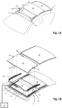
- Fig. 1A illustrates a vehicle roof 1 having an open roof assembly arranged therein.
- the open roof assembly comprises a moveable panel 2a and a fixed panel 2b.
- the moveable panel 2a is also referred to as a closure member, since the moveable panel 2a is moveable over a first roof opening 3a such to enable to open and to close the first roof opening 3a.
- a wind deflector 4 is arranged at a front side of the first roof opening 3a.
- the moveable panel 2a may be in a closed position, which is a position wherein the moveable panel 2a is arranged over and closes the first roof opening 3a and thus usually is arranged in a plane of the vehicle roof 1. Further, the moveable panel 2a may be in a tilted position, which is a position wherein a rear end RE of the moveable panel 2a is raised as compared to the closed position, while a front end FE of the moveable panel 2a is still in the closed position. Further, the moveable panel 2a may be in an open position, which is a position wherein the moveable panel 2a is slid open and the first roof opening 3a is partly or completely exposed.
- the illustrated vehicle roof 1 corresponds to a passenger car.
- the present invention is however not limited to passenger cars. Any other kind of vehicles that may be provided with a moveable panel are contemplated as well.
- Fig. 1B illustrates the same vehicle roof as shown in Fig. 1A having panels 2a and 2b.
- Fig. 1A shows the open roof assembly in the open position
- Fig. 1B is an exploded view of the open roof assembly in a closed position. Further, in this exploded view of Fig. 1B , it is shown that there is a second roof opening 3b.
- the first and second roof openings 3a, 3b are provided in a frame 5 of the open roof assembly. An edge 5a of the frame 5 defines the first roof opening 3a.
- the second roof opening 3b is arranged under the fixed panel 2b such that light may enter a vehicle interior passenger compartment through the fixed panel 2b, presuming that the fixed panel 2b is a glass panel or a similarly transparent panel, for example made of a plastic material or any other suitable material.
- the second roof opening 3b with a transparent or translucent fixed panel 2b is optional and may be omitted in another embodiment of the open roof assembly.
- the wind deflector 4 is commonly a flexible material, e.g. a woven or non-woven cloth having through holes arranged therein or a web or net.
- the flexible material is supported by a support structure 4a, e.g. a bar-like or tube-like structure, which structure is hingedly coupled, directly or indirectly, to the frame 5 at a hinge 4b.
- the wind deflector 4 is arranged in front of the first roof opening 3a and adapts air flow when the moveable panel 2a is in the open position. In its raised position, the wind deflector 4 reduces inconvenient noise due to air flow during driving. When the moveable panel 2a is in the closed position or in the tilted position, the wind deflector 4 is held down below the front end FE of the moveable panel 2a.
- the wind deflector 4 is raised by a spring force when the moveable panel 2a slides to an open position and the wind deflector 4 is pushed down by the moveable panel 2a when the moveable panel 2a slides back into its closed position.
- the moveable panel 2a is shown in an open position and the wind deflector 4 is shown in a raised position.
- Fig. 1B the moveable panel 2a is shown in a closed position and the wind deflector 4 is correspondingly shown in a position in which it is held down.
- Fig. 1B further illustrates a drive assembly having a first guide assembly 6a, a second guide assembly 6b, a first drive cable 7 and a second drive cable 8.
- the first and second guide assemblies 6a, 6b are arranged on respective side ends SE of the moveable panel 2a and may each comprise a guide and a mechanism.
- the guide is coupled to the frame 5, while the mechanism comprises moveable parts and is slideably moveable in the guide.
- the first and the second drive cables 7, 8 are provided between the mechanisms of the respective guide assemblies 6a, 6b and a electric motor 9.
- the drive cables 7, 8 couple the electric motor 9 to the mechanisms of the respective guide assemblies 6a, 6b such that upon operating the electric motor 9, the mechanisms start to move.
- a core of the drive cable 7, 8 is moved by the electric motor 9 such to push or pull on the mechanisms of the respective guides 6a, 6b.
- a drive assembly is well known in the art and is therefore not further elucidated herein.
- any other suitable drive assembly may be employed as well without departing from the scope of the present invention.
- an electric motor may be operatively arranged between the respective guides and the respective mechanisms of the guide assemblies 6a, 6b and, in such embodiment, a drive assembly may be omitted completely.
- the guide assemblies 6a, 6b may start movement with raising the rear end RE of the moveable panel 2a, thereby bringing the moveable panel 2a in the tilted position. Then, from the tilted position, the guide assemblies 6a, 6b may start to slide to bring the moveable panel 2a in the open position.
- the moveable panel 2a may be moveable to a tilted position by raising the rear end RE, while an open position is reached by first lowering the rear end RE and then sliding the moveable panel 2a under the fixed panel 2b or any other structure or element provided behind the rear end RE of the moveable panel 2a.
- the moveable panel 2a may be merely moveable between a closed position and a tilted position or between a closed position and an open position.
- the electric motor 9 is mounted near or below the front end FE of the moveable panel 2a at a recess 10. In another embodiment, the electric motor 9 may be positioned at any other suitable position or location. For example, the electric motor 9 may be arranged near or below the rear end RE of the moveable panel 2a or below the fixed panel 2b.
- a control module 11 is schematically illustrated and is operatively coupled to the electric motor 9.
- the control module 11 may be any kind of processing module, either a software controlled processing module or a dedicated processing module, like an ASIC, which are both well known to those skilled in the art.
- the control module 11 may be a stand-alone control module or it may be operatively connected to another control module, like a multipurpose, generic vehicle control module.
- the control module 11 may be embedded in or be part of such a generic vehicle control module.
- the control module 11 may be embodied by any control module suitable for, capable of and configured for performing operation of the electric motor 9 and thus the moveable roof assembly.
- Either or both of the moveable panel 2a and the fixed panel 2b may be an optically switchable transparent panel.
- Figs. 2A, 2B , 3A and 3B illustrate respective embodiments of a driver circuitry for driving and operating an optically switchable layer present in such an optically switchable transparent panel, as well known in the art.
- Such known layers include a PDLC, SPD, GHLC and electrochromic layers and other layers having optically switchable properties.
- An optically switchable material is operated by applying an electric field by application of a drive voltage between at least two electrode layers, between which the optically switchable material is arranged.
- optically switchable layers are well known in the art, a more detailed description thereof is omitted herein.
- a drive voltage circuit 20 and a switching circuitry 30 are connected in series with a segmented optically switchable panel 40.
- the segmented optically switchable panel 40 comprises four segments that are individually switchable: a first segment 41, a second segment 42, a third segment 43 and a fourth segment 44.
- the drive voltage circuitry 20 comprises a voltage input terminal 23a and a ground level input terminal 23b for receiving a system voltage, which usually corresponds to a battery voltage of about 12 V. Further, the drive voltage circuitry 20 comprises a voltage output terminal 24a and a neutral output terminal 24b for supplying a phase signal and a neutral signal, respectively, of the drive voltage to the switching circuitry 30.
- a communication line 25 is shown to run through the drive voltage circuitry 20, although the communication line 25 may not be regarded a part of the drive voltage circuitry 20 as it is not directly connected to other parts of the drive voltage circuitry 20.
- the communication line 25 may comprise one or more conductive leads (two are shown) and may use any kind of communication protocol. In a vehicle, commonly a bus communication using a LIN protocol or a CAN protocol is used, but other protocols and communication types may be applied as well.
- the drive voltage circuitry 20 comprises a drive voltage generation module 21 for generating the drive voltage from the system voltage.
- the voltage level may be increased from 12 V to a higher voltage, e.g. 30 V, 50 V, 70 V or an even higher voltage.
- a DC system voltage may be transformed to an AC voltage.
- the drive voltage is supplied to a voltage output terminal 24a and a neutral output terminal 24b, wherein the neutral output terminal 24b is supplied with a ground level (herein also referred to as a neutral signal) of the drive voltage, while the voltage output terminal 24a is supplied a phase signal, i.e. a voltage level different from the ground level.
- the drive voltage circuitry 20 further comprises a communication module 22, which is configured to receive an instruction signal, to interpret the instruction signal and to control the drive voltage generation module 21 in accordance with the instruction signal.
- the switching circuitry 30 comprises a number of switches 31.
- four switches 31 are shown, which number corresponds to the number of four segments 41 - 44 of the segmented optically switchable panel 40.
- the number of switches 31 are each connected to a respective one of the four segments 41 - 44 through a respective one of a number (in this embodiment four) of switching output terminals 35a - 35d.
- the phase signal of the drive voltage received at a phase input terminal 33a is selectively couplable to one or more of the segments 41 - 44 by selectively operating the respective switches 31.
- the neutral signal of the drive voltage is received at a neutral input terminal 33b and is supplied through a suitable connection to a ground-level electrode of the segmented optically switchable panel 40.
- the number of switches 31 are controlled by a controller unit 32, which is connected to each one of the number of switches 31. Further, the controller unit 32 is connected to the communication line 25 for receiving a user command signal from a user command panel 60.
- the user command panel 60 is designed and configured to receive a user input indicating a desired state of the optically switchable segments 41 - 44 and to generate a corresponding user command signal.
- the user command signal may represent the desired state of each of the segments 41 - 44 or may represent a desired change in status of one or more of the segments 41 - 44. Any other relevant data or instructions may be received through the communication line 25 as well.
- a shutdown of the vehicle may be communicated, in response to which the controller unit 32 may initiate a low-power mode of the drive voltage circuitry 20, the switching circuitry 30 and the segmented optically switchable panel 40.
- the communication line 25 may be dedicated to the optically switchable panel 40 and its control such that only the user command panel 60 is connected to the communication line 25 as shown.
- one or more other devices may be connected as well using the communication line 25 for communicating with other elements and devices unrelated to the operation of the optically switchable panel 40.
- the switching circuitry 30 receives the system voltage, e.g. battery voltage, at a system voltage input terminal 34a and a system ground voltage terminal 34b.
- the system voltage is supplied to the controller unit 32 for enabling operation thereof, while in practice the system voltage may be supplied to other parts of the switching circuitry 30 as well as apparent to those skilled in the art.
- the controller unit 32 is further connected to the communication module 22 through an instruction line 36 to supply the above-mentioned instruction signal to the communication module 22.
- the controller unit 32 is enabled to control the drive voltage circuitry 20 through the instruction signal.
- the instruction signal may instruct the drive voltage circuitry 20 to generate and supply the drive voltage as it may be needed to operate one or more of the segments 41 - 44 or may instruct the drive voltage circuitry 20 to cease supply of the drive voltage as it may no longer be needed to operate one or more of the segments 41 - 44.
- the instruction signal may also comprise other instructions. For example, a dimming instruction may be supplied such that a lower drive voltage may be generated and supplied such that the segments are not put in the first optical state or the second optical state, but are put in a third, intermediate optical state.
- a first wiring harness 51 may be provided to connect the system voltage and the communication line 25 to the drive voltage circuitry 20.
- a second wiring harness 52 comprising eight electrically conductive leads or wires, is used to connect the drive voltage circuitry 20 to the switching circuitry 30.
- a third wiring harness 53 connects the segments 41 - 44 and the ground-level electrode thereof to the switching circuitry 30.
- the third wiring harness 53 may be embodied in practice as a printed circuit on a circuit board, or the like. So, herein, the term 'wiring harness' should be interpreted broadly as a set of electrically conductive leads or wires.
- the number of conductive leads in the third wire harness 53 increases significantly. If in such embodiment the segmented optically switchable panel 40 is moveably arranged, a wiring between the switching circuitry 30 and the moveably arranged panel 40 becomes large and relatively stiff, thereby hampering a smooth running of the moveable panel 40 and reducing a size of a transparent area of the panel 40 as more cabling needs to be removed from view. Therefor, it may be preferred to mount the switching circuitry 30 on the moveable panel 40 as the switching circuitry 30 may be embodied in a relatively small package, e.g.
- the number of segments of the segmented optically switchable panel 40 does not affect the number of leads in the second wiring harness 52.
- Fig. 2B illustrates a second embodiment of the circuitry for operating a segmented optically switchable panel 40, wherein the number of leads in the second wiring harness 52 is reduced to six leads without affecting the functionality as shown in and described in relation to the embodiment of Fig. 2A .
- the embodiment of Fig. 2B is similar to the embodiment of Fig. 2A except that the instruction line 36 is omitted.
- the communication module 22 of the drive voltage circuitry 20 is directly connected to the communication line 25 through a communication sub-line 25a.
- the controller unit 32 may send the instruction signal to the communication module 22 over the communication line 25.
- the number of leads in the second wiring harness may be reduced and a size and stiffness of the second wiring harness may be reduced.
- Fig. 3A illustrates a third embodiment, wherein six leads are needed in the second wire harness 52.
- the number of switches 31 are illustrated as an integrated part of the controller unit 32. Such integration may also be used in the first and the second embodiments.
- the use of a non-integrated number of switches 31, as used in the first and the second embodiment may be used in the third and fourth embodiments of Figs. 3A and 3B , respectively.
- the communication module 22 is illustrated as an integrated part of the drive voltage generation module 21. Such integration may be used in the first and second embodiments as well, while the non-integrated circuitry of the first and second embodiments may be used in the third and fourth embodiments instead of the integrated circuitry, as apparent to those skilled in the art.
- the communication module 22 is operatively coupled to the neutral output terminal 24b and is not coupled to a dedicated communication line.
- the controller unit 32 is coupled to the neutral input terminal 33b and is configured to electrically connect the neutral input terminal 33b to the system ground input terminal 34b or to the system voltage input terminal 34a.
- the communication module 22 is configured to detect whether a voltage level on the neutral output terminal 24b corresponds to the system voltage level or to the system ground level.
- the communication module 22 may be configured to control the drive voltage generation module 21 to output the drive voltage, when the system voltage level is applied to the neutral output terminal 24b.
- the drive voltage generation module 21 will cease to output the drive voltage.
- the relatively high drive voltage will no longer be present on the second wire harness 52. Hence, a dead man switch control functionality for increased safety may be provided.
- the communication module 22 may be configured to be responsive of a change in the voltage level on the neutral output terminal 24b. In yet another configuration, the communication module 22 may be responsive to a predefined sequence of changes or voltage pulses, enabling the controller unit 32 to supply different kinds of instructions, instead of only a desired on or off state of the voltage generation module 21.
- an overhead user command panel 60a may be provided on the optically switchable panel 40.
- a touch sensitive user command panel 60a may be integrated in a laminated glass panel.
- Such an integrated user command panel 60a may be provided next to or instead of the user command panel 60.
- the integrated user command panel 60a may be directly coupled to the switching circuitry 30, in particular to the controller unit 32. If the user command panel 60 is omitted and only the integrated user command panel 60a is provided, the communication line 25 may not be needed and may be omitted as well.
- the second wiring harness 52 may comprise only four conductive leads.
- the second wire harness 52 comprises only four conductive leads.
- the communication line 25 is not fed through the second wire harness 52 directly. Instead, the communication line 25 is coupled to a modulation circuitry 26.
- the modulation circuitry 26 receives any user commands relevant to the operation of the optically switchable panel 40. The user commands are then supplied as the command signal to the voltage output terminal 24a and the neutral output terminal 24b, possibly but not necessarily via the communication module 22.
- the user commands may be send to the switching circuitry 30 over the second wire harness 52 by modulating the drive voltage (or as a modulated signal when no drive voltage is being supplied).
- an amplitude modulation, a frequency modulation or a duty-cycle modulation may be used.
- a DC drive voltage may be amplitude modulated; an AC drive voltage may be frequency modulated or duty-cycle modulated.
- the operation of the optically switchable panel 40 will not be affected.
- using a slightly higher drive voltage level than required for operating the optically switchable panel 40 ensures that any minor voltage drops due to amplitude modulation will not affect the operation.
- the controller unit 32 comprises a demodulation circuitry 37, which is coupled to the phase input terminal 33a and the neutral input terminal 33b and which is configured to demodulate the command signal.
- the command signal is then used by the controller unit 32 to control the number of switches 31 and the drive voltage circuitry 20, in particular the drive voltage generation module 21, in accordance with the command signal.
- Fig. 4 illustrates an embodiment of a transparent roof assembly comprising a first transparent panel 2a and a second transparent panel 2b arranged over a first roof opening 3a and a second roof opening 3b, respectively.
- the first transparent roof panel 2a may be moveably arranged.
- the first transparent roof panel 2a may be tiltable and/or slidable.
- the first roof opening 3a and the second roof opening 3b are provided in the frame 5, which frame 5 further supports the first and second transparent roof panels 2a, 2b.
- the first transparent panel 2a may comprise a segmented optically switchable panel.
- the second transparent panel 2b may comprise an optically switchable panel, that may or may not be segmented.
- Both panels 2a, 2b need a drive voltage for operating the optically switchable material layer. Therefore, e.g. for cost-effectiveness, a single drive voltage circuitry 20 is provided on the frame 5.
- the drive voltage circuitry 20 is arranged on a middle beam 5b that is arranged below a boundary between the first transparent panel 2a and the second transparent panel 2b, when the transparent panels 2a, 2b are in a closed position, i.e. covering the roof openings 3a, 3b, respectively.
- the drive voltage is supplied to each transparent panel 2a, 2b through a suitable wiring 52a, 52b, respectively.
- switching circuitry 30 is provided to control the individual segments.
- similar switching circuitry may be provided on the second transparent panel 2b.
- the transparent panels 2a, 2b each comprise a transparent area 201 and a peripheral opaque area 202.
- the opaque area 202 may be made opaque by application of a polymer layer, for example.
- the switching circuitry 30 is removed from plain sight by arranging the switching circuitry 30 in the opaque area 202.
- structural elements may be generated by application of three-dimensional (3D) printing techniques. Therefore, any reference to a structural element is intended to encompass any computer executable instructions that instruct a computer to generate such a structural element by three-dimensional printing techniques or similar computer controlled manufacturing techniques. Furthermore, any such reference to a structural element is also intended to encompass a computer readable medium carrying such computer executable instructions.
- the terms and phrases used herein are not intended to be limiting, but rather to provide an understandable description of the invention.
- the terms "a” or “an”, as used herein, are defined as one or more than one.
- the term plurality, as used herein, is defined as two or more than two.
- the term another, as used herein, is defined as at least a second or more.
- the terms including and/or having, as used herein, are defined as comprising (i.e., open language).
- the term coupled, as used herein, is defined as connected, although not necessarily directly.
Landscapes
- Physics & Mathematics (AREA)
- Engineering & Computer Science (AREA)
- Nonlinear Science (AREA)
- General Physics & Mathematics (AREA)
- Mechanical Engineering (AREA)
- Crystallography & Structural Chemistry (AREA)
- Chemical & Material Sciences (AREA)
- Optics & Photonics (AREA)
- Computer Hardware Design (AREA)
- Theoretical Computer Science (AREA)
- Mathematical Physics (AREA)
- Arrangements Of Lighting Devices For Vehicle Interiors, Mounting And Supporting Thereof, Circuits Therefore (AREA)
- Liquid Crystal (AREA)
Abstract
Description
- The invention relates to a transparent roof assembly for a vehicle roof and in particular to such a transparent roof assembly comprising a segmented optically switchable panel.
- An open-roof assembly is well-known. The open-roof assembly is configured to be mounted in a vehicle roof and comprises at least one moveably arranged closure member. The closure member is configured and arranged to cover an opening in the vehicle roof or at least partly uncover the opening in the vehicle roof. Usually, but not necessarily, the closure member is a transparent panel and comprises glass or a suitable plastics. The closure member may be configured to tilt or to slide.
- Further, it is known to provide a fixed, usually transparent panel in the vehicle roof of a passenger compartment to enable a sky view through the roof of the vehicle, for example, for any occupants in the passenger compartment.
- In either of the above-mentioned vehicle roofs, a transparent panel may be optically switchable. An optically switchable panel, as used herein, is a panel of which an optical property may be changed e.g. by an occupant. In particular, the optical property of the optically switchable panel may be changed by application of an electric field. Different kinds of such an optically switchable panel are known. For example, an electrochromic panel is known. Further, a number of kinds of such a panel that apply a liquid crystal layer are known. Some examples of the latter kind comprise a PDLC (polymer dispersed liquid crystal) layer, a SPD (suspended particle device) layer or a GHLC (guest host liquid crystal) layer.
- The optically switchable panel may comprise two electrode layers between which an optically switchable material is provided. A suitable electric voltage may be applied on these electrodes to thereby provide an electric field between the electrodes. The electric field induces the change of the optical property of the optically switchable material.
- Depending on the kind of switchable material applied, the electric voltage may be preferred to be an alternating (AC) voltage or a DC voltage. Further, a preferred voltage level may be dependent on the kind of switchable material and other properties. Usually, however, the voltage level is relatively high, i.e. higher than a battery voltage of a vehicle. So, the voltage level may need to be transformed to a higher voltage and/or may be transformed from a DC voltage to an AC voltage.
- For a segmented optically switchable panel, which comprises multiple segments that may be optically switched independently from each other, a relatively large number of individual connections between a driver circuitry and the optically switchable panel are needed. In particular as drive voltage circuitry for transforming the low DC battery voltage to the needed higher drive voltage may be relatively large and heavy for mounting such circuitry on the segmented optically switchable panel, it may be preferred to mount the drive voltage circuitry on a frame of the transparent roof assembly. Providing a wire for each segment of the optically switchable panel results in many wires, taking up space. Moreover, the wiring is preferred to be removed from view such that a transparent part of the segmented optically switchable panel needs to be reduced in size.
- It is known to provide a switching circuitry on the segmented optically switchable panel such that the drive voltage may be supplied to the switching circuitry by only two wires, while the many wires to the segments are arranged on the segmented optically switchable panel. It may however not be preferred to maintain the relatively high drive voltage constantly, but e.g. only when the drive voltage is needed to operate one or more segments of the segmented optically switchable panel, thereby reducing power consumption.
- In a first aspect, a transparent roof assembly for a vehicle roof according to
claim 1 is provided. The transparent roof assembly comprises a segmented optically switchable panel, a drive voltage circuitry and a switching circuitry. The segmented optically switchable panel comprises at least two independently switchable segments, each segment comprising a first optical state and a second optical state different from the first optical state. The drive voltage circuitry comprises a voltage input terminal for receiving a system voltage; a ground level input terminal for receiving a system ground; a voltage output terminal for supplying a phase signal of a drive voltage for switching between the first optical state and the second optical state; and a neutral output terminal for supplying a neutral signal of the drive voltage. The switching circuitry is configured to receive a command signal representing a user command indicating a desired optical state of each of the switchable segments and the switching circuitry comprises a system voltage input terminal for receiving the system voltage; a system ground input terminal for receiving the system ground; a phase input terminal for receiving the phase signal of the drive voltage; a neutral input terminal for receiving the neutral signal of the drive voltage; and at least two switching circuit output terminals for selectively operating the switchable segments corresponding to the command signal. Further, the switching circuitry is configured to control the supply of the drive voltage by the drive voltage circuitry. - In order to operate the optically switchable panel, the needed drive voltage, either AC or DC, is generated in the drive voltage circuitry, providing the drive voltage at its voltage output terminal and its neutral output terminal. For individually switching a number of segments of the segmented optically switchable panel, a switching circuitry is provided, which comprises a number of switching circuitry output terminals adapted to individually switch a corresponding number of segments of the segmented optically switchable panel. Preferably, the number of switching circuit output terminals corresponds to or exceeds the number of segments such that each segment is individually switchable. It is noted that, as apparent to those skilled in the art, the switching circuitry may switch the phase signal of the drive voltage or may switch the neutral signal of the drive voltage.
- The command signal representing the user command, which may indicate which segments need to be in the first optical state and which segments need to be in the second or even another optical state, is received at the switching circuitry. For example for safety reasons or to reduce power consumption, it may be preferred to remove the high drive voltage from the wiring between the drive voltage circuitry and the switching circuitry, when the high drive voltage is not needed for operating the optically switchable panel.
- The switching circuitry is provided with the user command and is thus enabled to determine whether the drive voltage is needed for operation or not. To keep control logic relatively simple and hence cost effective, the switching circuitry and the drive voltage circuitry are designed such that the switching circuitry may instruct the drive voltage circuitry to either supply or not supply the drive voltage.
- In an embodiment of the transparent roof assembly, the switching circuitry is configured to selectively connect the neutral input terminal to either the system ground or to the system voltage and the drive voltage circuitry is configured to compare a voltage on the neutral output terminal with the system voltage and the system ground to detect the voltage on the neutral output terminal and to switch the drive voltage depending on the voltage detected on the neutral output terminal.
- In order to keep a number of wires between the drive voltage circuitry and the switching circuitry as small as possible, the switching circuitry is configured to selectively connect the neutral input terminal to either the system ground or to the system voltage, which is detectable at the coupled neutral output terminal of the drive voltage circuitry. The drive voltage circuitry is configured to compare the voltage on the neutral output terminal with the system voltage and the system ground to detect whether the voltage on the neutral output terminal corresponds to the system ground or to the system voltage. Depending on the voltage detected on the neutral output terminal, the drive voltage circuitry switches the drive voltage on the voltage output terminal and the neutral output terminal or removes the drive voltage from the voltage output terminal and the neutral output terminal. Thus, without additional wiring, the switching circuitry is enabled to instruct the drive voltage circuitry.
- In an embodiment, the transparent roof assembly comprises a frame and the segmented optically switchable panel is arranged moveably relative to the frame, wherein the drive voltage circuitry is arranged on the frame and the switching circuitry is arranged on the segmented optically switchable panel. A flexible cabling is functionally coupled between the drive voltage circuitry and the switching circuitry. To keep a number of wires between the statically arranged frame and the moveably arranged segmented optically switchable panel small, it may be desired to mount the switching circuitry on the segmented optically switchable panel. However, the drive voltage circuitry may be relatively large and may therefore be desired not to be mounted on the segmented optically switchable panel.
- In an embodiment, the transparent roof assembly comprises a user command panel, the user command panel being configured to receive the user command and to generate the command signal and the user command panel being functionally coupled to the switching circuitry for supplying the command signal. The user command panel may be mounted on the segmented optically switchable panel or on a frame of the transparent roof assembly, for example. In another embodiment, the user command panel may be integrated in a dashboard of the vehicle or any other part of the vehicle. In a particular embodiment of the transparent roof assembly, wherein the segmented optically switchable panel comprises the user command panel, the user command panel may comprise mechanically operated switches or electronically operated switches like touch-sensitive switches. Such switches may be mounted on the segmented optically switchable panel or be integrated in the segmented optically switchable panel, e.g. being arranged between two glass plies, or the like.
- In a particular embodiment of the transparent roof assembly, the user command panel is electrically coupled to the drive voltage circuitry for supplying the command signal to the drive voltage circuitry. Further, the drive voltage circuitry comprises a modulation circuitry, the modulation circuitry being configured to modulate the drive voltage in accordance with the command signal and the switching circuitry comprises a demodulation circuitry to demodulate the drive voltage to thereby retrieve and receive the command signal. If the user command panel is not mounted on the segmented optically switchable panel, a number of wires to the segmented optically switchable panel may be reduced by providing the command signal by modulating the drive signal. Modulating may include that the modulation circuitry modulates at least one of an amplitude of the drive voltage, a frequency of the drive voltage and a duty cycle of the drive voltage.
- In an embodiment, the transparent roof assembly comprises a frame, a first transparent panel and a second transparent panel, the first transparent panel comprising a segmented optically switchable panel and the second transparent panel comprising an optically switchable panel, wherein the drive voltage circuitry is arranged on the frame, and wherein the switching circuitry is arranged on the first transparent panel. In a particular embodiment thereof, the second transparent panel comprises a segmented optically switchable panel and a further switching circuitry is arranged on the second transparent panel.
- In an aspect, a vehicle comprising an embodiment of the above-described vehicle roof assembly is provided.
- In an embodiment, the vehicle comprises a vehicle body and the transparent roof assembly comprises a frame mounted on the vehicle body, the segmented optically switchable panel being arranged moveably relative to the frame, wherein the drive voltage circuitry is arranged on the vehicle body and the switching circuitry is arranged on the segmented optically switchable panel, a flexible cabling being functionally coupled between the drive voltage circuitry and the switching circuitry. Thus, the drive voltage circuitry may be arranged anywhere in the vehicle, which may allow for more freedom of design, for example, as the size and shape may be less restricted than when mounted in or on the roof assembly.
- Further scope of applicability of the present invention will become apparent from the detailed description given hereinafter. However, it should be understood that the detailed description and specific examples, while indicating embodiments of the invention, are given by way of illustration only, since various changes and modifications within the scope of the invention will become apparent to those skilled in the art from this detailed description with reference to the appended schematical drawings, in which:
- Fig. 1A
- shows a perspective view of a vehicle roof with an open roof assembly;
- Fig. 1B
- shows an exploded view of the open roof assembly of
Fig. 1A ; - Fig. 2A
- illustrates a circuit diagram of a first embodiment of circuitry for use with a transparent roof assembly having a segmented optically switchable transparent panel;
- Fig. 2B
- illustrates a circuit diagram of a second embodiment of circuitry for use with a transparent roof assembly having a segmented optically switchable transparent panel;
- Fig. 3A
- illustrates a circuit diagram of a third embodiment of circuitry for use with a transparent roof assembly having a segmented optically switchable transparent panel;
- Fig. 3B
- illustrates a circuit diagram of a fourth embodiment of circuitry for use with a transparent roof assembly having a segmented optically switchable transparent panel;
- Fig. 4
- shows a perspective view of a fifth embodiment of a transparent roof assembly.
- The present invention will now be described with reference to the accompanying drawings, wherein the same reference numerals have been used to identify the same or similar elements throughout the several views.
-
Fig. 1A illustrates avehicle roof 1 having an open roof assembly arranged therein. The open roof assembly comprises amoveable panel 2a and a fixedpanel 2b. Themoveable panel 2a is also referred to as a closure member, since themoveable panel 2a is moveable over a first roof opening 3a such to enable to open and to close thefirst roof opening 3a. Awind deflector 4 is arranged at a front side of thefirst roof opening 3a. - In the illustrated embodiment, the
moveable panel 2a may be in a closed position, which is a position wherein themoveable panel 2a is arranged over and closes the first roof opening 3a and thus usually is arranged in a plane of thevehicle roof 1. Further, themoveable panel 2a may be in a tilted position, which is a position wherein a rear end RE of themoveable panel 2a is raised as compared to the closed position, while a front end FE of themoveable panel 2a is still in the closed position. Further, themoveable panel 2a may be in an open position, which is a position wherein themoveable panel 2a is slid open and thefirst roof opening 3a is partly or completely exposed. - It is noted that the illustrated
vehicle roof 1 corresponds to a passenger car. The present invention is however not limited to passenger cars. Any other kind of vehicles that may be provided with a moveable panel are contemplated as well. -
Fig. 1B illustrates the same vehicle roof as shown inFig. 1A having panels Fig. 1A shows the open roof assembly in the open position,Fig. 1B is an exploded view of the open roof assembly in a closed position. Further, in this exploded view ofFig. 1B , it is shown that there is a second roof opening 3b. The first andsecond roof openings frame 5 of the open roof assembly. Anedge 5a of theframe 5 defines thefirst roof opening 3a. - The second roof opening 3b is arranged under the fixed
panel 2b such that light may enter a vehicle interior passenger compartment through the fixedpanel 2b, presuming that the fixedpanel 2b is a glass panel or a similarly transparent panel, for example made of a plastic material or any other suitable material. The second roof opening 3b with a transparent or translucent fixedpanel 2b is optional and may be omitted in another embodiment of the open roof assembly. - The
wind deflector 4 is commonly a flexible material, e.g. a woven or non-woven cloth having through holes arranged therein or a web or net. The flexible material is supported by asupport structure 4a, e.g. a bar-like or tube-like structure, which structure is hingedly coupled, directly or indirectly, to theframe 5 at ahinge 4b. - The
wind deflector 4 is arranged in front of the first roof opening 3a and adapts air flow when themoveable panel 2a is in the open position. In its raised position, thewind deflector 4 reduces inconvenient noise due to air flow during driving. When themoveable panel 2a is in the closed position or in the tilted position, thewind deflector 4 is held down below the front end FE of themoveable panel 2a. - Usually, the
wind deflector 4 is raised by a spring force when themoveable panel 2a slides to an open position and thewind deflector 4 is pushed down by themoveable panel 2a when themoveable panel 2a slides back into its closed position. InFig. 1A , themoveable panel 2a is shown in an open position and thewind deflector 4 is shown in a raised position. InFig. 1B , themoveable panel 2a is shown in a closed position and thewind deflector 4 is correspondingly shown in a position in which it is held down. -
Fig. 1B further illustrates a drive assembly having a first guide assembly 6a, asecond guide assembly 6b, afirst drive cable 7 and asecond drive cable 8. The first andsecond guide assemblies 6a, 6b are arranged on respective side ends SE of themoveable panel 2a and may each comprise a guide and a mechanism. The guide is coupled to theframe 5, while the mechanism comprises moveable parts and is slideably moveable in the guide. The first and thesecond drive cables respective guide assemblies 6a, 6b and aelectric motor 9. - The
drive cables electric motor 9 to the mechanisms of therespective guide assemblies 6a, 6b such that upon operating theelectric motor 9, the mechanisms start to move. In particular, a core of thedrive cable electric motor 9 such to push or pull on the mechanisms of therespective guides 6a, 6b. Such a drive assembly is well known in the art and is therefore not further elucidated herein. Still, any other suitable drive assembly may be employed as well without departing from the scope of the present invention. Moreover, in a particular embodiment, an electric motor may be operatively arranged between the respective guides and the respective mechanisms of theguide assemblies 6a, 6b and, in such embodiment, a drive assembly may be omitted completely. - In the illustrated embodiment, the
guide assemblies 6a, 6b may start movement with raising the rear end RE of themoveable panel 2a, thereby bringing themoveable panel 2a in the tilted position. Then, from the tilted position, theguide assemblies 6a, 6b may start to slide to bring themoveable panel 2a in the open position. The present invention is however not limited to such embodiment. For example, in another embodiment, themoveable panel 2a may be moveable to a tilted position by raising the rear end RE, while an open position is reached by first lowering the rear end RE and then sliding themoveable panel 2a under the fixedpanel 2b or any other structure or element provided behind the rear end RE of themoveable panel 2a. In further exemplary embodiments, themoveable panel 2a may be merely moveable between a closed position and a tilted position or between a closed position and an open position. - In the illustrated embodiment, the
electric motor 9 is mounted near or below the front end FE of themoveable panel 2a at arecess 10. In another embodiment, theelectric motor 9 may be positioned at any other suitable position or location. For example, theelectric motor 9 may be arranged near or below the rear end RE of themoveable panel 2a or below the fixedpanel 2b. - A
control module 11 is schematically illustrated and is operatively coupled to theelectric motor 9. Thecontrol module 11 may be any kind of processing module, either a software controlled processing module or a dedicated processing module, like an ASIC, which are both well known to those skilled in the art. Thecontrol module 11 may be a stand-alone control module or it may be operatively connected to another control module, like a multipurpose, generic vehicle control module. In yet another embodiment, thecontrol module 11 may be embedded in or be part of such a generic vehicle control module. Essentially, thecontrol module 11 may be embodied by any control module suitable for, capable of and configured for performing operation of theelectric motor 9 and thus the moveable roof assembly. - Either or both of the
moveable panel 2a and the fixedpanel 2b may be an optically switchable transparent panel.Figs. 2A, 2B ,3A and 3B illustrate respective embodiments of a driver circuitry for driving and operating an optically switchable layer present in such an optically switchable transparent panel, as well known in the art. Such known layers include a PDLC, SPD, GHLC and electrochromic layers and other layers having optically switchable properties. An optically switchable material is operated by applying an electric field by application of a drive voltage between at least two electrode layers, between which the optically switchable material is arranged. As such optically switchable layers are well known in the art, a more detailed description thereof is omitted herein. - Referring to
Fig. 2A , in a first embodiment of the above-mentioned driver circuitry, adrive voltage circuit 20 and a switchingcircuitry 30 are connected in series with a segmented opticallyswitchable panel 40. The segmented opticallyswitchable panel 40 comprises four segments that are individually switchable: afirst segment 41, asecond segment 42, athird segment 43 and afourth segment 44. - The
drive voltage circuitry 20 comprises avoltage input terminal 23a and a groundlevel input terminal 23b for receiving a system voltage, which usually corresponds to a battery voltage of about 12 V. Further, thedrive voltage circuitry 20 comprises avoltage output terminal 24a and aneutral output terminal 24b for supplying a phase signal and a neutral signal, respectively, of the drive voltage to the switchingcircuitry 30. Acommunication line 25 is shown to run through thedrive voltage circuitry 20, although thecommunication line 25 may not be regarded a part of thedrive voltage circuitry 20 as it is not directly connected to other parts of thedrive voltage circuitry 20. Thecommunication line 25 may comprise one or more conductive leads (two are shown) and may use any kind of communication protocol. In a vehicle, commonly a bus communication using a LIN protocol or a CAN protocol is used, but other protocols and communication types may be applied as well. - The
drive voltage circuitry 20 comprises a drivevoltage generation module 21 for generating the drive voltage from the system voltage. For example, the voltage level may be increased from 12 V to a higher voltage, e.g. 30 V, 50 V, 70 V or an even higher voltage. Further, a DC system voltage may be transformed to an AC voltage. The drive voltage is supplied to avoltage output terminal 24a and aneutral output terminal 24b, wherein theneutral output terminal 24b is supplied with a ground level (herein also referred to as a neutral signal) of the drive voltage, while thevoltage output terminal 24a is supplied a phase signal, i.e. a voltage level different from the ground level. - The
drive voltage circuitry 20 further comprises acommunication module 22, which is configured to receive an instruction signal, to interpret the instruction signal and to control the drivevoltage generation module 21 in accordance with the instruction signal. - The switching
circuitry 30 comprises a number ofswitches 31. In this illustrated embodiment, fourswitches 31 are shown, which number corresponds to the number of four segments 41 - 44 of the segmented opticallyswitchable panel 40. The number ofswitches 31 are each connected to a respective one of the four segments 41 - 44 through a respective one of a number (in this embodiment four) of switchingoutput terminals 35a - 35d. The phase signal of the drive voltage received at aphase input terminal 33a is selectively couplable to one or more of the segments 41 - 44 by selectively operating the respective switches 31. The neutral signal of the drive voltage is received at aneutral input terminal 33b and is supplied through a suitable connection to a ground-level electrode of the segmented opticallyswitchable panel 40. - The number of
switches 31 are controlled by acontroller unit 32, which is connected to each one of the number ofswitches 31. Further, thecontroller unit 32 is connected to thecommunication line 25 for receiving a user command signal from auser command panel 60. Theuser command panel 60 is designed and configured to receive a user input indicating a desired state of the optically switchable segments 41 - 44 and to generate a corresponding user command signal. The user command signal may represent the desired state of each of the segments 41 - 44 or may represent a desired change in status of one or more of the segments 41 - 44. Any other relevant data or instructions may be received through thecommunication line 25 as well. For example, a shutdown of the vehicle may be communicated, in response to which thecontroller unit 32 may initiate a low-power mode of thedrive voltage circuitry 20, the switchingcircuitry 30 and the segmented opticallyswitchable panel 40. Further, depending on a practical embodiment of thecommunication line 25, thecommunication line 25 may be dedicated to the opticallyswitchable panel 40 and its control such that only theuser command panel 60 is connected to thecommunication line 25 as shown. In another embodiment, however, one or more other devices may be connected as well using thecommunication line 25 for communicating with other elements and devices unrelated to the operation of the opticallyswitchable panel 40. - The switching
circuitry 30 receives the system voltage, e.g. battery voltage, at a systemvoltage input terminal 34a and a systemground voltage terminal 34b. In the illustrated embodiment, the system voltage is supplied to thecontroller unit 32 for enabling operation thereof, while in practice the system voltage may be supplied to other parts of the switchingcircuitry 30 as well as apparent to those skilled in the art. - The
controller unit 32 is further connected to thecommunication module 22 through aninstruction line 36 to supply the above-mentioned instruction signal to thecommunication module 22. Thecontroller unit 32 is enabled to control thedrive voltage circuitry 20 through the instruction signal. In particular, the instruction signal may instruct thedrive voltage circuitry 20 to generate and supply the drive voltage as it may be needed to operate one or more of the segments 41 - 44 or may instruct thedrive voltage circuitry 20 to cease supply of the drive voltage as it may no longer be needed to operate one or more of the segments 41 - 44. In particular embodiments the instruction signal may also comprise other instructions. For example, a dimming instruction may be supplied such that a lower drive voltage may be generated and supplied such that the segments are not put in the first optical state or the second optical state, but are put in a third, intermediate optical state. - A
first wiring harness 51 may be provided to connect the system voltage and thecommunication line 25 to thedrive voltage circuitry 20. Asecond wiring harness 52, comprising eight electrically conductive leads or wires, is used to connect thedrive voltage circuitry 20 to the switchingcircuitry 30. Athird wiring harness 53 connects the segments 41 - 44 and the ground-level electrode thereof to the switchingcircuitry 30. Thethird wiring harness 53 may be embodied in practice as a printed circuit on a circuit board, or the like. So, herein, the term 'wiring harness' should be interpreted broadly as a set of electrically conductive leads or wires. - In an embodiment wherein the number of segments is larger that the illustrated embodiment of four segments, e.g. an embodiment comprising 10 segments, the number of conductive leads in the
third wire harness 53 increases significantly. If in such embodiment the segmented opticallyswitchable panel 40 is moveably arranged, a wiring between the switchingcircuitry 30 and the moveably arrangedpanel 40 becomes large and relatively stiff, thereby hampering a smooth running of themoveable panel 40 and reducing a size of a transparent area of thepanel 40 as more cabling needs to be removed from view. Therefor, it may be preferred to mount the switchingcircuitry 30 on themoveable panel 40 as the switchingcircuitry 30 may be embodied in a relatively small package, e.g. a semiconductor chip, or the like, and using a printed circuit on a thin foil, or the like, for thethird wiring harness 53. In such embodiment, the number of segments of the segmented opticallyswitchable panel 40 does not affect the number of leads in thesecond wiring harness 52. -
Fig. 2B illustrates a second embodiment of the circuitry for operating a segmented opticallyswitchable panel 40, wherein the number of leads in thesecond wiring harness 52 is reduced to six leads without affecting the functionality as shown in and described in relation to the embodiment ofFig. 2A . - The embodiment of
Fig. 2B is similar to the embodiment ofFig. 2A except that theinstruction line 36 is omitted. In this second embodiment, thecommunication module 22 of thedrive voltage circuitry 20 is directly connected to thecommunication line 25 through acommunication sub-line 25a. For example, assuming a bus communication protocol being used on thecommunication line 25, thecontroller unit 32 may send the instruction signal to thecommunication module 22 over thecommunication line 25. Thus, the number of leads in the second wiring harness may be reduced and a size and stiffness of the second wiring harness may be reduced. - All other parts and functions of the second embodiment correspond to the parts and functions of the first embodiment of
Fig. 2A and are therefore not repeated here. -
Fig. 3A illustrates a third embodiment, wherein six leads are needed in thesecond wire harness 52. Compared to the first and second embodiments, the number ofswitches 31 are illustrated as an integrated part of thecontroller unit 32. Such integration may also be used in the first and the second embodiments. As apparent to those skilled in the art, the use of a non-integrated number ofswitches 31, as used in the first and the second embodiment, may be used in the third and fourth embodiments ofFigs. 3A and 3B , respectively. - In the third and fourth embodiments of
Fig. 3A and 3B , thecommunication module 22 is illustrated as an integrated part of the drivevoltage generation module 21. Such integration may be used in the first and second embodiments as well, while the non-integrated circuitry of the first and second embodiments may be used in the third and fourth embodiments instead of the integrated circuitry, as apparent to those skilled in the art. - In the third embodiment of
Fig. 3A , thecommunication module 22 is operatively coupled to theneutral output terminal 24b and is not coupled to a dedicated communication line. Thecontroller unit 32 is coupled to theneutral input terminal 33b and is configured to electrically connect theneutral input terminal 33b to the systemground input terminal 34b or to the systemvoltage input terminal 34a. Thecommunication module 22 is configured to detect whether a voltage level on theneutral output terminal 24b corresponds to the system voltage level or to the system ground level. - The
communication module 22 may be configured to control the drivevoltage generation module 21 to output the drive voltage, when the system voltage level is applied to theneutral output terminal 24b. In particular, if the system voltage level is applied using a switch requiring a permanent actuation voltage, any error or malfunctioning may result in a release of the switch and thus removal of the system voltage level from theneutral output terminal 24b. As a result, the drivevoltage generation module 21 will cease to output the drive voltage. The relatively high drive voltage will no longer be present on thesecond wire harness 52. Hence, a dead man switch control functionality for increased safety may be provided. - In another configuration of the
communication module 22, thecommunication module 22 may be configured to be responsive of a change in the voltage level on theneutral output terminal 24b. In yet another configuration, thecommunication module 22 may be responsive to a predefined sequence of changes or voltage pulses, enabling thecontroller unit 32 to supply different kinds of instructions, instead of only a desired on or off state of thevoltage generation module 21. - In a practical embodiment, an overhead
user command panel 60a may be provided on the opticallyswitchable panel 40. For example, a touch sensitiveuser command panel 60a may be integrated in a laminated glass panel. Such an integrateduser command panel 60a may be provided next to or instead of theuser command panel 60. The integrateduser command panel 60a may be directly coupled to the switchingcircuitry 30, in particular to thecontroller unit 32. If theuser command panel 60 is omitted and only the integrateduser command panel 60a is provided, thecommunication line 25 may not be needed and may be omitted as well. In such an embodiment, thesecond wiring harness 52 may comprise only four conductive leads. - In the fourth embodiment illustrated in
Fig. 3B , thesecond wire harness 52 comprises only four conductive leads. Compared to the third embodiment, thecommunication line 25 is not fed through thesecond wire harness 52 directly. Instead, thecommunication line 25 is coupled to amodulation circuitry 26. Themodulation circuitry 26 receives any user commands relevant to the operation of the opticallyswitchable panel 40. The user commands are then supplied as the command signal to thevoltage output terminal 24a and theneutral output terminal 24b, possibly but not necessarily via thecommunication module 22. The user commands may be send to the switchingcircuitry 30 over thesecond wire harness 52 by modulating the drive voltage (or as a modulated signal when no drive voltage is being supplied). Depending on the kind of drive voltage, an amplitude modulation, a frequency modulation or a duty-cycle modulation may be used. For example, a DC drive voltage may be amplitude modulated; an AC drive voltage may be frequency modulated or duty-cycle modulated. As apparent to those skilled in the art, using a suitable drive voltage and modulation method, the operation of the opticallyswitchable panel 40 will not be affected. For example, using a slightly higher drive voltage level than required for operating the opticallyswitchable panel 40 ensures that any minor voltage drops due to amplitude modulation will not affect the operation. - The
controller unit 32 comprises ademodulation circuitry 37, which is coupled to thephase input terminal 33a and theneutral input terminal 33b and which is configured to demodulate the command signal. The command signal is then used by thecontroller unit 32 to control the number ofswitches 31 and thedrive voltage circuitry 20, in particular the drivevoltage generation module 21, in accordance with the command signal. - All other parts and functions of the fourth embodiment correspond to the parts and functions of the third embodiment of
Fig. 3A and are therefore not repeated here. -
Fig. 4 illustrates an embodiment of a transparent roof assembly comprising a firsttransparent panel 2a and a secondtransparent panel 2b arranged over a first roof opening 3a and a second roof opening 3b, respectively. As described in relation toFig. 1A , the firsttransparent roof panel 2a may be moveably arranged. For example, the firsttransparent roof panel 2a may be tiltable and/or slidable. The first roof opening 3a and the second roof opening 3b are provided in theframe 5, whichframe 5 further supports the first and secondtransparent roof panels - The first
transparent panel 2a may comprise a segmented optically switchable panel. The secondtransparent panel 2b may comprise an optically switchable panel, that may or may not be segmented. Bothpanels drive voltage circuitry 20 is provided on theframe 5. In particular, in this embodiment, thedrive voltage circuitry 20 is arranged on amiddle beam 5b that is arranged below a boundary between the firsttransparent panel 2a and the secondtransparent panel 2b, when thetransparent panels roof openings - The drive voltage is supplied to each
transparent panel suitable wiring transparent panel 2a, switchingcircuitry 30 is provided to control the individual segments. Optionally, similar switching circuitry may be provided on the secondtransparent panel 2b. - The
transparent panels transparent area 201 and a peripheralopaque area 202. Theopaque area 202 may be made opaque by application of a polymer layer, for example. The switchingcircuitry 30 is removed from plain sight by arranging the switchingcircuitry 30 in theopaque area 202. - Detailed embodiments of the present invention are disclosed herein; however, it is to be understood that the disclosed embodiments are merely exemplary of the invention, which can be embodied in various forms. Therefore, specific structural and functional details disclosed herein are not to be interpreted as limiting, but merely as a basis for the claims and as a representative basis for teaching one skilled in the art to variously employ the present invention in expectedly any appropriately detailed structure. In particular, features presented and described in separate dependent claims may be applied in combination and any advantageous combination of such claims are herewith disclosed.
- Further, it is contemplated that structural elements may be generated by application of three-dimensional (3D) printing techniques. Therefore, any reference to a structural element is intended to encompass any computer executable instructions that instruct a computer to generate such a structural element by three-dimensional printing techniques or similar computer controlled manufacturing techniques. Furthermore, any such reference to a structural element is also intended to encompass a computer readable medium carrying such computer executable instructions.
- Further, the terms and phrases used herein are not intended to be limiting, but rather to provide an understandable description of the invention. The terms "a" or "an", as used herein, are defined as one or more than one. The term plurality, as used herein, is defined as two or more than two. The term another, as used herein, is defined as at least a second or more. The terms including and/or having, as used herein, are defined as comprising (i.e., open language). The term coupled, as used herein, is defined as connected, although not necessarily directly.
- The invention being thus described it is apparent that the same may be varied in many ways. Such variations are not to be regarded as a departure from the spirit and scope of the invention, and all such modifications as would be apparent to one skilled in the art are intended to be included within the scope of the following claims.
Claims (13)
- A transparent roof assembly for a vehicle roof, the transparent roof assembly comprising a segmented optically switchable panel (40), a drive voltage circuitry (20) and a switching circuitry (30),the segmented optically switchable panel comprising at least two independently switchable segments (41 - 44), each segment comprising a first optical state and a second optical state different from the first optical state,the drive voltage circuitry comprising- a voltage input terminal (23a) for receiving a system voltage;- a ground level input terminal (23b) for receiving a system ground;- a voltage output terminal (24a) for supplying a phase signal of a drive voltage for switching between the first optical state and the second optical state; and- a neutral output terminal (24b) for supplying a neutral signal of the drive voltage; andthe switching circuitry being configured to receive a command signal representing a user command indicating a desired optical state of each of the switchable segments and comprising- a system voltage input terminal (34a) for receiving the system voltage;- a system ground input terminal (34b) for receiving the system ground;- a phase input terminal (33a) for receiving the phase signal of the drive voltage;- a neutral input terminal (33b) for receiving the neutral signal of the drive voltage; and- at least two switching circuit output terminals (35a - 35d) for selectively operating the switchable segments corresponding to the command signal,wherein the switching circuitry is configured to control the supply of the drive voltage by the drive voltage circuitry.
- The transparent roof assembly according to claim 1, wherein the switching circuitry is configured to selectively connect the neutral input terminal to either the system ground or to the system voltage; and
wherein the drive voltage circuitry is configured to compare a voltage on the neutral output terminal with the system voltage and the system ground and to switch the drive voltage depending on the voltage detected on the neutral output terminal. - The transparent roof assembly according to claim 1, wherein the transparent roof assembly comprises a frame (5), the segmented optically switchable panel being arranged moveably relative to the frame, wherein the drive voltage circuitry is arranged on the frame and the switching circuitry is arranged on the segmented optically switchable panel, a flexible cabling (52a, 52b) being functionally coupled between the drive voltage circuitry and the switching circuitry.
- The transparent roof assembly according to claim 1, wherein the transparent roof assembly comprises a user command panel, the user command panel (60, 60a) being configured to receive the user command from a user and to generate the command signal and the user command panel being functionally coupled to the switching circuitry for supplying the command signal to the switching circuitry.
- The transparent roof assembly according to claim 4, wherein the segmented optically switchable panel comprises the user command panel (60a).
- The transparent roof assembly according to claim 4, wherein- the user command panel is electrically coupled to the drive voltage circuitry for supplying the command signal to the drive voltage circuitry;- the drive voltage circuitry comprises a modulation circuitry (26), the modulation circuitry being configured to modulate the drive voltage in accordance with the command signal; and- the switching circuitry comprises a demodulation circuitry (37) to demodulate the drive voltage to thereby retrieve and receive the command signal.
- The transparent roof assembly according to claim 6, wherein the modulation circuitry (26) modulates an amplitude of the drive voltage.
- The transparent roof assembly according to claim 6, wherein the modulation circuitry (26) modulates a frequency of the drive voltage.
- The transparent roof assembly according to claim 6, wherein the modulation circuitry (26) modulates a duty cycle of the drive voltage.
- The transparent roof assembly according to claim 1, wherein the transparent roof assembly comprises a frame (5), a first transparent panel (2a) and a second transparent panel (2b), the first transparent panel comprising a segmented optically switchable panel (40) and the second transparent panel comprising an optically switchable panel,wherein the drive voltage circuitry (20) is arranged on the frame, andwherein the switching circuitry (30) is arranged on the first transparent panel.
- The transparent roof assembly according to claim 10, wherein the second transparent panel comprises a segmented optically switchable panel and wherein a further switching circuitry is arranged on the second transparent panel.
- A vehicle comprising the vehicle roof assembly according to claim 1.
- The vehicle according to claim 12, wherein the vehicle comprises a vehicle body and the transparent roof assembly comprises a frame (5) mounted on the vehicle body, the segmented optically switchable panel being arranged moveably relative to the frame, wherein the drive voltage circuitry is arranged on the vehicle body and the switching circuitry is arranged on the segmented optically switchable panel, a flexible cabling (52, 52a, 52b) being functionally coupled between the drive voltage circuitry and the switching circuitry.
Priority Applications (2)
| Application Number | Priority Date | Filing Date | Title |
|---|---|---|---|
| EP22201169.4A EP4354213A1 (en) | 2022-10-12 | 2022-10-12 | Transparent roof assembly comprising a segmented optically switchable panel |
| CN202311268603.5A CN117863846A (en) | 2022-10-12 | 2023-09-27 | Transparent roof assembly including segmented optically switchable panels |
Applications Claiming Priority (1)
| Application Number | Priority Date | Filing Date | Title |
|---|---|---|---|
| EP22201169.4A EP4354213A1 (en) | 2022-10-12 | 2022-10-12 | Transparent roof assembly comprising a segmented optically switchable panel |
Publications (1)
| Publication Number | Publication Date |
|---|---|
| EP4354213A1 true EP4354213A1 (en) | 2024-04-17 |
Family
ID=83691151
Family Applications (1)
| Application Number | Title | Priority Date | Filing Date |
|---|---|---|---|
| EP22201169.4A Pending EP4354213A1 (en) | 2022-10-12 | 2022-10-12 | Transparent roof assembly comprising a segmented optically switchable panel |
Country Status (2)
| Country | Link |
|---|---|
| EP (1) | EP4354213A1 (en) |
| CN (1) | CN117863846A (en) |
Citations (4)
| Publication number | Priority date | Publication date | Assignee | Title |
|---|---|---|---|---|
| WO2007146862A2 (en) * | 2006-06-09 | 2007-12-21 | Gentex Corporation | Variable transmission window system |
| US20210356772A1 (en) * | 2020-05-13 | 2021-11-18 | Inalfa Roof Systems Group B.V. | Drive circuit for driving an electro-optical device |
| US20220250448A1 (en) * | 2021-02-05 | 2022-08-11 | Agp America S.A. | Multiple circuit variable light transmission glazing system |
| EP4194237A1 (en) * | 2021-12-13 | 2023-06-14 | Inalfa Roof Systems Group B.V. | Transparent roof assembly comprising a segmented optically switchable panel |
-
2022
- 2022-10-12 EP EP22201169.4A patent/EP4354213A1/en active Pending
-
2023
- 2023-09-27 CN CN202311268603.5A patent/CN117863846A/en active Pending
Patent Citations (4)
| Publication number | Priority date | Publication date | Assignee | Title |
|---|---|---|---|---|
| WO2007146862A2 (en) * | 2006-06-09 | 2007-12-21 | Gentex Corporation | Variable transmission window system |
| US20210356772A1 (en) * | 2020-05-13 | 2021-11-18 | Inalfa Roof Systems Group B.V. | Drive circuit for driving an electro-optical device |
| US20220250448A1 (en) * | 2021-02-05 | 2022-08-11 | Agp America S.A. | Multiple circuit variable light transmission glazing system |
| EP4194237A1 (en) * | 2021-12-13 | 2023-06-14 | Inalfa Roof Systems Group B.V. | Transparent roof assembly comprising a segmented optically switchable panel |
Also Published As
| Publication number | Publication date |
|---|---|
| CN117863846A (en) | 2024-04-12 |
Similar Documents
| Publication | Publication Date | Title |
|---|---|---|
| EP4194237B1 (en) | Transparent roof assembly comprising a segmented optically switchable panel | |
| CN113741073B (en) | Driving circuit for driving electro-optical device | |
| EP0504549A2 (en) | Multiplex communication control unit | |
| US20080061599A1 (en) | Windbreak device | |
| CN103568971A (en) | Electric pedal device for vehicle | |
| CN112673144A (en) | Synchronous switch for electric window | |
| CN208827916U (en) | Car steering wheel and vehicle | |
| US7880390B2 (en) | Vehicular room illuminating lamp | |
| JP2000003652A (en) | In-vehicle input device | |
| CN117863846A (en) | Transparent roof assembly including segmented optically switchable panels | |
| US11840174B2 (en) | Vehicular overhead console with light transmissive panel | |
| JP4475796B2 (en) | Equipment control device | |
| CN215042422U (en) | Lamp adjustment system and vehicle | |
| CN1530261A (en) | window regulator control switch | |
| US20210291845A1 (en) | Central control unit for a vehicle interior | |
| CN110614964A (en) | Console assembly | |
| EP4328055A1 (en) | Transparent roof assembly comprising a segmented optically switchable panel | |
| EP4175146A1 (en) | Drive circuitry for an optically switchable panel, a vehicle roof assembly provided with such drive circuitry and method for driving an optically switchable panel | |
| CN216805089U (en) | Optically switchable panel device, control unit and transparent roof assembly | |
| EP1316486A2 (en) | Power control device | |
| CN115822414B (en) | Control method of automobile window opening and closing system | |
| CN222921488U (en) | Integrated main driving switch system and vehicle | |
| CN217048524U (en) | Vehicle with solar power supply system | |
| CN220114549U (en) | In-car reading lamp product with electric glasses box | |
| CN217632185U (en) | Control system and vehicle of electron vehicle window membrane |
Legal Events
| Date | Code | Title | Description |
|---|---|---|---|
| PUAI | Public reference made under article 153(3) epc to a published international application that has entered the european phase |
Free format text: ORIGINAL CODE: 0009012 |
|
| STAA | Information on the status of an ep patent application or granted ep patent |
Free format text: STATUS: THE APPLICATION HAS BEEN PUBLISHED |
|
| AK | Designated contracting states |
Kind code of ref document: A1 Designated state(s): AL AT BE BG CH CY CZ DE DK EE ES FI FR GB GR HR HU IE IS IT LI LT LU LV MC ME MK MT NL NO PL PT RO RS SE SI SK SM TR |
|
| STAA | Information on the status of an ep patent application or granted ep patent |
Free format text: STATUS: REQUEST FOR EXAMINATION WAS MADE |
|
| 17P | Request for examination filed |
Effective date: 20241004 |
|
| RBV | Designated contracting states (corrected) |
Designated state(s): AL AT BE BG CH CY CZ DE DK EE ES FI FR GB GR HR HU IE IS IT LI LT LU LV MC ME MK MT NL NO PL PT RO RS SE SI SK SM TR |
|
| GRAP | Despatch of communication of intention to grant a patent |
Free format text: ORIGINAL CODE: EPIDOSNIGR1 |
|
| STAA | Information on the status of an ep patent application or granted ep patent |
Free format text: STATUS: GRANT OF PATENT IS INTENDED |
|
| RIC1 | Information provided on ipc code assigned before grant |
Ipc: G02F 1/133 20060101AFI20260115BHEP Ipc: G02F 1/163 20060101ALI20260115BHEP Ipc: B60J 3/04 20060101ALI20260115BHEP Ipc: E06B 9/24 20060101ALN20260115BHEP |
|
| INTG | Intention to grant announced |
Effective date: 20260127 |
|
| GRAS | Grant fee paid |
Free format text: ORIGINAL CODE: EPIDOSNIGR3 |
|
| GRAA | (expected) grant |
Free format text: ORIGINAL CODE: 0009210 |
|
| STAA | Information on the status of an ep patent application or granted ep patent |
Free format text: STATUS: THE PATENT HAS BEEN GRANTED |