EP4354181A1 - A method for performing a correction of a ionospheric error affecting pseudo-ranges measurements in a gnss receiver, corresponding receiver apparatus and computer program product - Google Patents
A method for performing a correction of a ionospheric error affecting pseudo-ranges measurements in a gnss receiver, corresponding receiver apparatus and computer program product Download PDFInfo
- Publication number
- EP4354181A1 EP4354181A1 EP23199224.9A EP23199224A EP4354181A1 EP 4354181 A1 EP4354181 A1 EP 4354181A1 EP 23199224 A EP23199224 A EP 23199224A EP 4354181 A1 EP4354181 A1 EP 4354181A1
- Authority
- EP
- European Patent Office
- Prior art keywords
- pseudo
- ionospheric
- checking
- ionospheric error
- error correction
- Prior art date
- Legal status (The legal status is an assumption and is not a legal conclusion. Google has not performed a legal analysis and makes no representation as to the accuracy of the status listed.)
- Granted
Links
Images




Classifications
-
- G—PHYSICS
- G01—MEASURING; TESTING
- G01S—RADIO DIRECTION-FINDING; RADIO NAVIGATION; DETERMINING DISTANCE OR VELOCITY BY USE OF RADIO WAVES; LOCATING OR PRESENCE-DETECTING BY USE OF THE REFLECTION OR RERADIATION OF RADIO WAVES; ANALOGOUS ARRANGEMENTS USING OTHER WAVES
- G01S19/00—Satellite radio beacon positioning systems; Determining position, velocity or attitude using signals transmitted by such systems
- G01S19/01—Satellite radio beacon positioning systems transmitting time-stamped messages, e.g. GPS [Global Positioning System], GLONASS [Global Orbiting Navigation Satellite System] or GALILEO
- G01S19/03—Cooperating elements; Interaction or communication between different cooperating elements or between cooperating elements and receivers
- G01S19/07—Cooperating elements; Interaction or communication between different cooperating elements or between cooperating elements and receivers providing data for correcting measured positioning data, e.g. DGPS [differential GPS] or ionosphere corrections
- G01S19/072—Ionosphere corrections
-
- G—PHYSICS
- G01—MEASURING; TESTING
- G01S—RADIO DIRECTION-FINDING; RADIO NAVIGATION; DETERMINING DISTANCE OR VELOCITY BY USE OF RADIO WAVES; LOCATING OR PRESENCE-DETECTING BY USE OF THE REFLECTION OR RERADIATION OF RADIO WAVES; ANALOGOUS ARRANGEMENTS USING OTHER WAVES
- G01S19/00—Satellite radio beacon positioning systems; Determining position, velocity or attitude using signals transmitted by such systems
- G01S19/01—Satellite radio beacon positioning systems transmitting time-stamped messages, e.g. GPS [Global Positioning System], GLONASS [Global Orbiting Navigation Satellite System] or GALILEO
- G01S19/03—Cooperating elements; Interaction or communication between different cooperating elements or between cooperating elements and receivers
- G01S19/04—Cooperating elements; Interaction or communication between different cooperating elements or between cooperating elements and receivers providing carrier phase data
Definitions
- Embodiments of the present disclosure relate to solutions concerning for performing a correction of a ionospheric error affecting pseudo-ranges measurements in a GNSS receiver.
- the present disclosure in particular refers to techniques for performing a correction of a ionospheric error affecting pseudo-ranges measurements in a GNSS receiver using the L1 and L5 carrier.
- PS Position Sensor
- the processor In order to calculate user position, the processor needs to combine the distance measurements (also known as pseudo-ranges) between user and all the satellites in view measured by GNSS receiver following a process called triangulation. Final position accuracy reflects the quality of such measurements. They are affected by several error factors that are compensated successfully in receiver processing according the state of art.
- the GNSS receiver elaborates the elapsed time between satellite signal transmission and reception. This equals the distance between user and satellites (also known as pseudo range). Combining the distance measurements from several satellites through a triangulation technique the GNSS device determines user position accurately. Some errors are present on the distance measurements and they need to be compensated by the receiver in order to preserve position accuracy. They include:
- the signal delays caused by ionosphere crossing is not always predictable.
- one critical error factor is the delay accumulated by GNSS signals while crossing the ionosphere layer.
- the latter are depending on the level of solar activity modulating ionosphere electron content.
- activity on solar surface charges ionosphere atmospheric layer during daytime, causing an increase of its Total Electron Content (TEC - expressed in electrons/m 3 ).
- TEC Total Electron Content
- the higher is TEC the higher is the delay accumulated by electromagnetic signals while crossing it.
- Dual frequency GNSS receivers can cancel the ionospheric error combining distance measurement taken from two different carriers transmitted by same satellites.
- this kind of combination introduces an additional amount of noise, hence its usage - while improving solution in bad ionospheric conditions - if used in good solar condition is detrimental for performance.
- a first known solution uses Klobuchar/Nequick models. These are generic models implemented into standard receivers. They need to be updated daily with data downloaded by the satellites. They provide a good level of compensation cancelling 50-70% of errors derived in normal solar activity. Klobuchar/ Nequick are conceived as global models, hence providing a compromise, not being optimized for a specific region, while ionospheric conditions vary very much from one continent to another.
- a second known solution uses Satellite Based Augmentation Systems (SBAS).
- SBAS Satellite Based Augmentation Systems
- GSS Global System for Mobile Communications
- GLONASS Global System for Mobile Communications
- Europe features the EGNOS satellite system; North America the WAAS system; Japan the QZSS; India the IRNSS.
- SBAS has the advantage to provide ionospheric compensation data that are optimized for the specific geographic area in which the user is located.
- the time granularity of the provided information is still daily at least, meaning that SBAS is not able to cope with non-standard ionospheric behaviour caused by abnormal solar activity.
- a third solution uses a combination of distance measurements from different broadcasted frequencies.
- Some GNSS constellations transmit two different signals on different carriers.
- Receivers that are capable to receive both frequencies can perform a linear combination/difference of the two distance measurements obtained for each satellite.
- Such combination is known in the art as Iono-Free Linear combination (IFLC) and produces a new distance measurement for given satellite which is free from any ionospheric effect.
- IFLC is virtually eliminating 100% of ionospheric induced error, however, being a difference, it increases by a fixed amount the noise floor of distance measurements. So, while the outliers related to extreme solar activity are removed, the typical accuracy in normal condition is worse than standard methods. Additionally, the difference is influenced by potential other biases present on the measurements. For example, in urban environments, signal reflections caused by tall buildings deteriorate the quality of IFLC measurements. Finally, not all the satellites feature dual frequency transmission; hence there is less availability of such measurements compared to single frequency ones.
- one or more of the above obj ectives is achieved by means of a method having the features specifically set forth in the claims that follow.
- Embodiments moreover concern a related receiver apparatus and computer program product.
- the present disclosure relates to a method for performing a correction of a ionospheric error affecting pseudo-ranges measurements in a GNSS receiver receiving a plurality of satellite signals from a plurality of satellites of the constellation of satellites,
- said performing one or more checking operations further comprises performing, prior to said evaluating a solar activity one or more operations checking if the receiver is in condition to measure correctly said solar activity.
- said one or more operations checking if the receiver is in condition to measure correctly said solar activity comprise one or more of:
- said performing one or more checking operations comprise a sequence of the operations:
- said evaluating a solar activity and enabling performing said Ionospheric Free Linear Combination if the solar activity is above a given threshold comprises
- said checking if the GNSS receiver is in an urban environment comprises inputting the standard pseudo range measurements to a Least Square regression operation to calculate raw user position data from pseudo-range data, supplying residual errors for each pseudo-range measurement derived from said Least Square calculation, picking the maximum value among such residual errors, performing a low pass filtering, in particular IIR filtering, on said maximum residual error value obtaining a urban environment indication value, checking if said urban environment indication value is greater than a respective threshold in the affirmative detecting and signaling that the receiver is in an urban condition, otherwise an open sky condition is detected and signaled.
- the present disclosure relates also to a receiver apparatus configured to perform the method of any of the previous embodiments.
- the present disclosure relates also to a computer program product directly loadable into the internal memory of a digital computer, comprising software code portions for performing the steps of the method of any of the previous embodiments.
- a navigation receiver operates by down converting to quasi baseband the input signal received from the satellites, which is transmitted at L band (1-2 GHz), using a local oscillator to step down the input frequency and allow a baseband digital management of the Satellite information.
- GNSS Global Navigation Satellite System
- GLONASS Global'naya Navigatsionnaya Sputnikovaya
- Galileo System or other types of satellite-based positioning systems
- GNSS Global Navigation Satellite System
- GPS Global Positioning System
- GLONASS Global'naya Navigatsionnaya Sputnikovaya
- Galileo System or other types of satellite-based positioning systems
- such global satellite positioning system 1000 comprises a constellation of a number NS of satellites S 1 -S NS and at least a receiving apparatus 100.
- the satellite signals used in the GNSS (Global Navigation Satellite System) are of the CDMA-type (Code Division Multiple Access).
- the satellite signals reception at the receiving apparatus 100 is implemented through the following, sequentially performed, standard steps: analog filtering, frequency conversion and digitization, acquisition, tracking, decoding and positioning.
- the receiving apparatus 100 comprises an antenna 1, an analog receiving module AFE (Analog Front End), provided with a radiofrequency (RF) stage 2, and an analog-digital converter 3 (ADC), which can be implemented by hardware modules.
- AFE Analog Front End
- RF radiofrequency
- ADC analog-digital converter
- the receiving apparatus 100 comprises a digital processing module DFE (Digital Front End), including an acquisition module 4 (ACQ), and a tracking module 5 (TRK).
- DFE Digital Front End
- ACQ acquisition module 4
- TRK tracking module 5
- the receiving apparatus 100 is provided with a sub-frame recovery module (SBF-REC) 6, an ephemerides processing and pseudo-range calculation module 7 (EPH-PSR), a satellites orbits prediction module 8 (ORB-PRE), a satellite type detecting module 9 (MOD-DET), a satellite position calculation module 10 (SAT-POS), and a user position calculation module 11 (USR-POS).
- SBF-REC sub-frame recovery module
- EPH-PSR ephemerides processing and pseudo-range calculation module 7
- ORB-PRE satellites orbits prediction module 8
- MOD-DET satellite type detecting module 9
- SAT-POS satellite position calculation module
- USB-POS user position calculation module
- acquisition module 4, tracking module 5 can be implemented by hardware, while the remaining modules 6-11 can be implemented by software.
- acquisition module 4 and tracking module 5 can also be implemented by a hardware and software combination.
- the receiving apparatus 100 is provided with a central processing unit, memories (mass memory and/or working storage) and respective interfaces (not shown in figures), comprising a microprocessor or microcontroller, for running the software resident in it.
- the antenna 1 receives a plurality of signals s 0 ,...,s NS-1 from one or more satellites S 0 -S NS-1 of the constellation of satellites operating in system 1000.
- these signals can be modulated on a carrier having a frequency of about 1.5 GHz.
- each received signal transports a pseudo-random code and a message for the data communication.
- the pseudo-random code known as CA code, for example at 1 MHz, is used for distinguishing a satellite from another, and enables the receiving apparatus 100 to measure the time instant at which has been transmitted a signal by a corresponding satellite.
- Pseudo-random code is implemented by a sequence of pulses, called chips.
- the radio frequency stage 2 operates on the signals received by antenna 1 (of the analog type) and converts them to the base band or to an intermediate frequency.
- Analog-digital converter 3 converts the intermediate frequency signals to corresponding digital signals.
- the radio-frequency stage 2 operates the conversion at an intermediate frequency using the frequency of a local signal LS which may be supplied by a Temperature Compensated Crystal Oscillator (TCXO) 2a.
- TCXO Temperature Compensated Crystal Oscillator
- the acquisition block 4 identifies in the digital signals originated by the analog-digital converter 3 the satellites in visibility, testing their presence by trying to match their transmitted PRN (Pseudo Random Noise) code sequence, i.e. the CA code, with a corresponding local replica and when a peak confirmation is found it provides the initial GNSS information, i.e. code/frequency information to an elementary Intermediate Frequency tracking correlation block. Further, the acquisition module 4 detects a plurality of parameters associated to the satellites and used for time tracking the satellite.
- PRN Physical Random Noise
- the data navigation message transports data (for example at a bit rate equal to 50 Hz) and particularly is modulated based on the Binary Phase Shift Keying (BPSK) technique. Further, data navigation message is hierarchically divided in frames and sub-frames and transports several information, among them a plurality of parameters used for determining the orbit and consequently the position of satellites.
- BPSK Binary Phase Shift Keying
- the tracking module 5 has plural tracking channels, indicated by a channel index i from 0 to NS-1, in particular indicated as TRK 0 ... TRK NS-1 and each is allocated to a different satellite of the constellation.
- the tracking module 5 is configured to operate as carrier tracking loop, which can be designed to follow either the phase of the incoming signal - using Phase Lock Loops (PLL), or the Doppler frequency of the incoming signal using Frequency Lock Loops (FLL).
- PLL Phase Lock Loops
- FLL Frequency Lock Loops
- the tracking module 5 is configured to supply data to the sub-frame recovery module 6, as a time sequence of samples pairs, indicated with ⁇ I, Q ⁇ .
- Each sample ⁇ I, Q ⁇ is for example the result of a coherent integration, respectively instep and quadrature, of a bit of 20 ms, performed by a correlator based on the modulation technique Binary Phase Shift Keying (BPSK), each samples pair ⁇ I, Q ⁇ represents a transmitted bit.
- BPSK Binary Phase Shift Keying
- the Doppler frequency and the transfer time of the GPS signal transmitted by a satellite S 1 -S NS are determined.
- Each i-th tracking channel TRK i includes thus, in a way known per se, a frequency locked loop and also a carrier to noise ratio meter, which estimates the carrier to noise ratio C/No, for instance every N (e.g. 10) accumulation periods of frequency loop of the tracking channel, where the elementary coherent one is bounded by the bit length of the signal being considered, e.g. of 20 ms for the GPS L1/CA case, and aligned to the 1 st millisecond of the bit.
- N e.g. 10
- the sub-frame recovery module 6, by means of suitable algorithms, decodes the different received sub-frames forming the navigation data message.
- the ephemerides processing and pseudo-range calculation module 7 stores the satellite orbit, as ephemerides data, and calculates the existent distances between the satellites and the receiving apparatus 100: such distances are called pseudo-range.
- FIG 1 are indicated two pseudo-ranges, a raw pseudo range measurement ⁇ i 1 from a first carrier signal, in the example L1 carrier signal, for the i th satellite and a raw pseudo range measurement from a second carrier signal, in the example L5 carrier signal, for i th satellite ⁇ i 5 .
- the satellite position calculation module 10 calculates the positions of the satellites expressed by 3D coordinates, at the moment of transmission.
- the satellite orbit prediction module 8 can be activated for assisting the ephemerides processing and pseudo-range calculation module 7 and/or satellite position calculation module 10 when the ephemerides data are not available at the receiving apparatus 100.
- the satellite type detecting module 9 is configured to determine the type of the tracked satellite and by it the solar radiation pressure model to be used in the orbit prediction by the satellite orbit prediction module 8, according to modes that will be described in the following as examples.
- the satellite type detecting module 9 enables to determine the type of satellite in order to select the solar radiation pressure model which better provides for the shape, mass and size of a satellite.
- the satellite position calculation module 10 operates on the time for transferring the GPS signal together with the reception time (known due to a clock inside the receiving apparatus 100).
- the satellite position calculation module 10 operates in order to evaluate how much time is required to the signal from each satellite for reaching the receiving apparatus 100, evaluating in this way the distance from the corresponding satellite (pseudo-range).
- the user position calculation module 11 calculates the position of the receiving apparatus 100 based on the distances of the receiving apparatus 100 preferably from at least four satellites and based on the positions of the same satellites, known at this processing stage. In the following, the position of the receiving apparatus 100 (practically coinciding with the user position) is be called "fix”.
- modules 10 and 11 are indicated as belonging to a navigation processing module 12 which receiving such pseudo range measurements, previously calculated by said GNSS receiver, in particular by module 6, calculate the position velocity time PVT of the receiver.
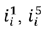
- Such pseudo range measurements ⁇ i 1 , ⁇ i 5 may pertain a first carrier signal and a second carrier signal, in particular L1 and L5.
- the method here described in variant embodiments may be used with any GNSS band combination. For example it can be used processing signals from L1 and L2 bands.
- the navigation processing operation may be in general defined in more general schematic as the operation following the tracking channels in module 5, and may include sometimes also the pseudo-range measurements calculation. In the present description, as mentioned is considered as an operation receiving the pseudo-range measurements as input and calculating the position velocity time PVT as output, i.e., it may correspond only to the user module 11 and related operations or it may include additional operations.
- the tracking module 5 includes a plurality of channels, i.e. tracking correlation blocks which are usually let working in parallel each tuned on a different satellite PRN code and frequency, among the ones previously identified by the acquisition block 4, with the goal to confirm or eventually discard the acquisition hypothesis for every of them.
- the stable locked tracking phase starts. It consists into tightly following both the frequency offset (velocity) and the code phase (distance) of the satellite vehicle being analyzed and to demodulate the position and time information embedded in its bit stream. This information is then provided for instance to a Kalman Filter to triangulate the receiver position, e.g. in block 14.
- the tracking channel includes a correlator which comprises a PRN (pseudorandom noise) delayed sequence generator.
- PRN Pseudo-Random Noise
- the GNSS signals received at the receiver includes a ranging code modulated into the carrier, also called Pseudo-Random Noise (PRN) code, which spreads the spectrum and allows retrieving ranging information. Therefore, it is required that the tracking channel include a PRN delayed sequence generator, which generates PRN sequences which are early, punctual or delayed one with respect to the other to perform correlation with the ranging codes.
- the solution here described in brief refers to a method for performing a correction of a ionospheric error affecting pseudo-ranges measurements in a GNSS receiver receiving satellite, e.g. s 0 ,...,s NS-1 from one or more satellites S 0 -S NS-1 ,,
- the solution here described identifies if it is convenient performing the IFLC obtaining sufficiently accurate measurements with zero ionospheric error correction, or it is preferrable to use a ionospheric error correction with another standard method, e.g. Klobuchar/Nequick models and/or SBAS.
- Solar activity detection is used as the main enabling criteria, which can be however accompanied by other enabling criteria, cascaded, such as latitude detection, day detection, urban environment detection.
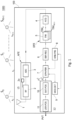
- the navigation processing module 12 receiving the raw pseudo range measurement ⁇ i 1 from L1 carrier signal for the i th satellite and a raw pseudo range measurement from L5 carrier signal for i th satellite ⁇ i 5 fron block 6, and in general from the GNSS digital signal processing, is here schematized comprising a measurement correction block 13 and a position calculation block 14. The may be for instance both comprised in the user position block 11,
- the measurement correction block 13 as said implements an operation receiving pseudo range measurements ⁇ i 1 , ⁇ i 5 from the GNSS Digital Signal Processing algorithms, in particular from the pseudo-range measurement calculation in block 6, and applying to them corrections c i 1 for predictable errors.
- Such corrections c i 1 may be provided by GNSS service operators and downloaded by the satellite signals.
- the position calculation block 14 implements an operation taking as input the corrected pseudo-range measurements outputted by block 13, combining them in order to solve the GNSS positioning and time estimation problem, as per equations defined in literature.
- the most classic and simple method to do this is through a Least Square regression approach; other embodiments may use different state estimation techniques, such, as mentioned above, as Extended Kalman Filters (EKF), or also Particle Filters
- the block 14 calculating the position, velocity, time estimation PVT feeds back some quantities to the correction block 13, i.e., a receiver clock bias b (estimated runtime by position calculation algorithm), a correction d j 1 for receiver band 1 RF delay, a correction for receiver band 5 RF delay d j 5 .
- a receiver clock bias b estimated runtime by position calculation algorithm
- figure 2A it is shown a known arrangement of the navigation processing operation 12, while in figure 2B it is schematized an arrangement according to the solution here described, which provides a ionospheric error correction management operation 15, after the operation of the correction block 13, which evaluates which quantities are fed to the position calculation block 14.
- the ionospheric error correction management operation 15 comprising a standard ionospheric error correction operation 17 receiving the pseudo range measurements ⁇ i 1 , ⁇ i 5 , after correction for predictable errors in the correction block 13,and outputting a vector comprising such pseudo range measurements ⁇ i 1 , ⁇ i 5 along with respective ionospheric error corrections i i 1 , i i 5 , which, as explained above, are obtained by standard methods, e.g. Klobuchar and or SBAS, from the corrections provided by GNSS service operators and downloaded by the satellite signals.
- standard methods e.g. Klobuchar and or SBAS
- the ionospheric error correction management operation 15 comprises also a IFLC Activation Logic 16, which aims to decide which input data must be used to feed position calculation algorithm in block 14, the data from standard operation 17 or data from the IFLC Activation Logic 16, according to a given criterion, evaluating if the IFLC improves the accuracy of the measurement of the position velocity time PVT information, i.e., if such ionospheric conditions occur, e.g., a solar storm is occurring, in correctly measurable conditions, such as, for instance, latitude, night time and open sky, as better explained in the following.
- a solar correction condition active SR_ON is detected and signaled, the standard pseudo range measurements ⁇ i 1 , ⁇ i 5 along with respective ionospheric error corrections i i 1 , i i 5 , derived from GNSS navigation data (either through Klobuchar model or SBAS, if available) are supplied to the the position calculation 14.
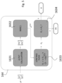
- FIG 4 it shown a block schematics representing an embodiments the IFLC Activation Logic 16.
- IFLC Activation Logic in embodiments may perform a sequence of cascaded check operations that - if all passed - lead to declaration of solar risk correction active, i.e., condition SR_ON and consequently use of the of IFLC measurements, ⁇ i 15 and ionospheric error correction i equal to zero.
- the IFLC Activation Logic 16 performs first a latitude threshold detection 161. Since the effects of strong solar activity are visible especially at low latitude, the latitude threshold detection 161 checks if the receiver is in such condition.
- a latitude threshold may be set in a configurable manner, thus the check is to check if
- the information regarding latitude l is obtainable from the satellite signals or from the current position information obtained by the receiver.
- the solar actvity is higher for lower latitudes, thus:
- the day condition is checked based on current user position and UTC time. This is an operation known per se.
- the check performed in the example is if the day condition is day DY.
- a subsequent urban environment detection 163 operation is performed. Due to measurements errors caused by reflections, which are higher order, when the receiver, for instance on a vehicle, is in dense urban environment it is not convenient to activate a solar activity detection 164, as described below, and to use IFLC measurements.
- the urban environment detection 163 operation is detailed in the following with reference to figure 5 .
- the solar activity detection 164 operation comprises comparing downloaded (standard) ionospheric error corrections c i to the ones calculated by mean of dual frequency technique, this block identifies solar anomalies, as better detailed in the following with reference to figure 6A and 6B .
- the solar correction condition inactive SR_OFF is detected and signaled.
- the operation 164 gives a positive result, i.e. solar activity is detected STM, the solar correction condition inactive SR_OFF is detected and signaled.
- the method may include only the operation 164 of solar detection, for instance letting to the user to evaluate if conditions for solar detection occur, or only one or more of the operations 161, 162, 163, which represent operations of checking conditions which allows the solar detection operation 164 to operate correctly. Also, only one or more of the operations 161, 162, 163 may be performed, and in a different sequence with respect to that described with respect to figure 4 . Also it would be possible for user to connect the device to a host which has access to ionospheric databases for instance in a research institute, although generally this option is not adopted in the automotive field for cost reasons.
- the solution here described refers in general to a method for performing a correction of a ionospheric error affecting pseudo-ranges measurements in a GNSS receiver 100 receiving a plurality of satellite signals s 0 ,...,s NS-1 from a plurality of satellites S 0 -S NS-1 of the constellation of satellites,
- performing one or more checking operations 161, 162, 163, 164 further comprises performing, prior to such evaluating 164 a solar activity, e.g. It, one or more operations, which are for instance 161, 162, 163, checking if the receiver 100 is in condition to measure correctly said solar activity. As said otherwise a manual checking by the user may be possible.
- Such one or more operations e.g. 161, 162, 163, checking if the GNSS receiver 100 may comprise one or more or of the operations:
- the checking operations 161, 162, 163 may be in a different order or less in number, provided that solar activity detection 164 is finally performed.
- FIG. 5 a block schematics is here shown detailing the urban environment detection operation 163.
- the urban environment detection operation 163 allows to understand if vehicle is crossing urban environments, where the application of IFLC is not convenient, i.e., the solar correction condition inactive SR_OFF is detected and signaled in block 16 leading to use of the standard pseudo range measurements ⁇ i 1 , ⁇ i 5 along with respective ionospheric error corrections i i 1 , i i 5 , derived from GNSS navigation data (either through Klobuchar model or SBAS, if available), which are supplied to the the position calculation 14.
- GNSS navigation data either through Klobuchar model or SBAS, if available
- the standard pseudo range measurements ⁇ i 1 , ⁇ i 5 are input to a Least Square regression operation 1631 to calculate raw user position from pseudo-ranges data. This operation is known per se a way to obtain PVT from the pseudo-ranges.
- the output of block 163 is a residual error dy i 1 dy i 5 of the Least Square calculation, dy i 1 being the residual error for the i-th satellite and the first carrier L1 and dy i 5 being the residual error for the i-th satellite and the second carrier L5.
- Such residual error dy i 1 dy i 5 is in general very low if all the pseudo-ranges from different satellites are consistent (which typically happens in open sky conditions) while increases sensibly when one or more data suffer biases from reflections by the surrounding buildings.
- the filtered urban indicator U t is then compared in an operation 1634 to a respective threshold U TH and if greater the urban condition U is detected and signaled, otherwise the open sky condition OS is detected and signaled.
- figure 6A it is shown a schematic of the solar detection operation 164.
- Figure 6B is further detailing some of the steps shown in figure 6A .
- the basic empiric rational on which it is based is that, in an open sky environment, if the solar activity follows expectations the ionospheric error correction broadcasted by GNSS satellites should be like the one calculated from dual frequency satellite information.
- the solar detection operation 164 receives as inputs the iono-affected pseudo range ⁇ i 1 and the ionospheric free one ⁇ i 15 first calculating in a step 1641 the dual frequency estimated ionospheric error correction for the i-th satellite , which is the difference (difference block 1641a in figure 6B ) between the raw iono-affected pseudo range ⁇ i 1 and the ionospheric free pseudo range ⁇ i 15 . As detailed in figure 6B an absolute value of such difference is calculated (block 1641b) as dual frequency estimated ionospheric error correction for the i-th satellite i i df .
- Such correction difference di i is accumulated in a step 1643 over the whole constellations of NS satellites S 0 -S NS-1 in view, and finally averaged in a step 1645, yielding a delta ionospheric error metric ⁇ i , or range difference, for the current measurement epoch.
- a check if new satellites are available in the constellation is performed. In the affirmative, it is returned to step 1641 to recalculate the correction difference di i with the new satellite constellations. Otherwise the averaging step 1645 is performed.
- the delta ionospheric error metric ⁇ i is heavily affected by the high noise on IFLC pseudo-ranges ⁇ i 15 ; hence a low pass filter stage 1646 (e.g., IIR filter) follows in order to smooth out such delta ionospheric error metric ⁇ i and make it consistent on a minute's time landscape.
- a low pass filter stage 1646 e.g., IIR filter
- Different type of low pass filtering may be used, alternative to IIR, among them FIR, Kalman Filter, Complementary filter, moving average.
- ionospheric metric indicator I t falls above a given threshold, as checked in a checking block 1647.
- STM solar activity state
- the solar correction condition active SR_ON is detected and signaled, and usage of IFLC pseudo-ranges in block 14 to calculate the position PVT is performed. Otherwise, the normal state NRM is detected and signaled, i.e.
- the solar correction condition inactive SR_ON is detected and signaled, and the standard pseudo range measurements ⁇ i 1 , ⁇ i 5 along with respective ionospheric error corrections i i 1 , i i 5 , derived from GNSS navigation data (either through Klobuchar model or SBAS, if available), are supplied to the the position calculation 14.
- modules 6-11 of the GNSS receiver 100 can be implemented by software. Also navigation processing 12 as a whole, and in particular any or all of modules 13, 14, 15, 16, 17 can be implemented by software in the receiver 100.
- the solution here described represents a compensation approach for the position error caused by ionosphere approach which is independent from user location.
- the solution here described represents a compensation approach which adaptively and seamlessly turns on and off depending on reception condition. Compared to prior solution, it can exploit IFLC only when really needed, avoiding to inject additional noise on solution or reduce measurement availability under benign solar condition or when user is located in a dense urban environment (where solar effects become less relevant compared to other environmental error factors like multipath).
Landscapes
- Engineering & Computer Science (AREA)
- Radar, Positioning & Navigation (AREA)
- Remote Sensing (AREA)
- Computer Networks & Wireless Communication (AREA)
- Physics & Mathematics (AREA)
- General Physics & Mathematics (AREA)
- Position Fixing By Use Of Radio Waves (AREA)
Abstract
Description
- Embodiments of the present disclosure relate to solutions concerning for performing a correction of a ionospheric error affecting pseudo-ranges measurements in a GNSS receiver.
- The present disclosure in particular refers to techniques for performing a correction of a ionospheric error affecting pseudo-ranges measurements in a GNSS receiver using the L1 and L5 carrier.
- In several applications and user cases (automotive, consumer fields) a Position Sensor (PS) is required. It is an electronic device composed by a GNSS receiver and a processor aiming to provide accurate position information to user application.
- In order to calculate user position, the processor needs to combine the distance measurements (also known as pseudo-ranges) between user and all the satellites in view measured by GNSS receiver following a process called triangulation. Final position accuracy reflects the quality of such measurements. They are affected by several error factors that are compensated successfully in receiver processing according the state of art.
- In particular, the GNSS receiver elaborates the elapsed time between satellite signal transmission and reception. This equals the distance between user and satellites (also known as pseudo range). Combining the distance measurements from several satellites through a triangulation technique the GNSS device determines user position accurately. Some errors are present on the distance measurements and they need to be compensated by the receiver in order to preserve position accuracy. They include:
- delays introduced by signal generation in satellite HW/SW;
- errors due to earth rotation;
- delays caused by troposphere;
- delays caused by receiver design;
- delays caused by ionosphere.
- All the error causes listed above, with the exception of signal delays caused by ionosphere, are predictable and compensated into the receiver either using standard modelling techniques or using compensation parameters downloaded by the satellite communication itself.
- The signal delays caused by ionosphere crossing is not always predictable. In particular, one critical error factor is the delay accumulated by GNSS signals while crossing the ionosphere layer. The latter are depending on the level of solar activity modulating ionosphere electron content. Hence in certain conditions (daytime, low latitude areas, periods of nonstandard sun activity such like solar storms) the amount of error caused by this is not predictable and affecting the solution. In particular, activity on solar surface charges ionosphere atmospheric layer during daytime, causing an increase of its Total Electron Content (TEC - expressed in electrons/m3). The higher is TEC, the higher is the delay accumulated by electromagnetic signals while crossing it. The higher is the signal carrier frequency, the smaller is such delay, e.g., 1 TEC unit causes 16 cm equivalent error on distance measurement, since a storm can determine an increase of tenth of TEC units, this translates in error of meters.
- Dual frequency GNSS receivers can cancel the ionospheric error combining distance measurement taken from two different carriers transmitted by same satellites. However, this kind of combination introduces an additional amount of noise, hence its usage - while improving solution in bad ionospheric conditions - if used in good solar condition is detrimental for performance.
- In particular, a first known solution uses Klobuchar/Nequick models. These are generic models implemented into standard receivers. They need to be updated daily with data downloaded by the satellites. They provide a good level of compensation cancelling 50-70% of errors derived in normal solar activity. Klobuchar/ Nequick are conceived as global models, hence providing a compromise, not being optimized for a specific region, while ionospheric conditions vary very much from one continent to another.
- A second known solution uses Satellite Based Augmentation Systems (SBAS). On top of classic GNSS constellations (GPS, Galileo, GLONASS,..) political actors from different area issued specific local satellite systems aiming to gather signal statistics for a given area and elaborated corrections for the ionospheric error tailored for a specific place. By way of example, Europe features the EGNOS satellite system; North America the WAAS system; Japan the QZSS; India the IRNSS. With respect to the Klobuchar/Nequick models, SBAS has the advantage to provide ionospheric compensation data that are optimized for the specific geographic area in which the user is located. However, the time granularity of the provided information is still daily at least, meaning that SBAS is not able to cope with non-standard ionospheric behaviour caused by abnormal solar activity.
- A third solution uses a combination of distance measurements from different broadcasted frequencies. Some GNSS constellations transmit two different signals on different carriers. Receivers that are capable to receive both frequencies can perform a linear combination/difference of the two distance measurements obtained for each satellite. Such combination is known in the art as Iono-Free Linear combination (IFLC) and produces a new distance measurement for given satellite which is free from any ionospheric effect. IFLC is virtually eliminating 100% of ionospheric induced error, however, being a difference, it increases by a fixed amount the noise floor of distance measurements. So, while the outliers related to extreme solar activity are removed, the typical accuracy in normal condition is worse than standard methods. Additionally, the difference is influenced by potential other biases present on the measurements. For example, in urban environments, signal reflections caused by tall buildings deteriorate the quality of IFLC measurements. Finally, not all the satellites feature dual frequency transmission; hence there is less availability of such measurements compared to single frequency ones.
- Therefore the known solutions presents each the above different drawback, making it difficult to have accurate measurements in every condition.
- In view of the above, it is an objective of the present disclosure to provide solutions which overcome one or more of the above drawbacks.
- According to one or more embodiments, one or more of the above obj ectives is achieved by means of a method having the features specifically set forth in the claims that follow. Embodiments moreover concern a related receiver apparatus and computer program product.
- The claims are an integral part of the technical teaching of the disclosure provided herein.
- As mentioned before, the present disclosure relates to a method for performing a correction of a ionospheric error affecting pseudo-ranges measurements in a GNSS receiver receiving a plurality of satellite signals from a plurality of satellites of the constellation of satellites,
- comprising in a navigation processing procedure performed at a GNSS receiver,
- receiving pseudo range measurements previously calculated by said GNSS receiver obtained from a first carrier signal and a second carrier signal in said satellite signals, in particular in GPS bands L1 and L5,
- performing a correction procedure of said pseudo-range measurements comprising
- compensating pseudo-range measurements for predictable errors obtaining corrected pseudo-ranges and
- applying to said corrected pseudo-range measurements a further ionospheric error correction calculation to obtain further ionospheric error correction values,
- performing a position calculation operation processing said corrected pseudo-range measurements and said ionospheric error corrections values and outputting position, velocity and time information of the GNSS receiver,
- wherein
- said applying to said corrected pseudo-ranges a further ionospheric error correction calculation to obtain further ionospheric error correction values,
- comprising
- performing one or more checking operations enabling performing a Ionosphere Free Linear Combination on said pseudo-ranges measurements obtaining Ionospheric Free Linear Combination pseudo-range measurements and supplying it to said position calculation operation only,
- otherwise performing a standard ionospheric error correction derived from GNSS navigation data, in particular by Klobuchar/Nequick models and/or SBAS, supplying the correspondingly standard ionospheric corrected pseudo-range measurements to said position calculation operation,
- said performing one or more checking operations comprising evaluating a solar activity and enabling performing said Ionospheric Free Linear Combination if the solar activity is above a given threshold.
- In variant embodiments, said performing one or more checking operations further comprises performing, prior to said evaluating a solar activity one or more operations checking if the receiver is in condition to measure correctly said solar activity.
- In variant embodiments, said one or more operations checking if the receiver is in condition to measure correctly said solar activity, comprise one or more of:
- checking if the latitude is below a latitude threshold,
- checking if a day condition is occurring,
- checking if the GNSS receiver is in an urban environment.
- In variant embodiments, said performing one or more checking operations comprise a sequence of the operations:
- checking if the latitude is below a latitude threshold,
- checking if a day condition is occurring,
- checking if the GNSS receiver is in an urban environment
- evaluating a solar activity and enabling performing said Ionospheric Free Linear Combination if the solar activity is above a given threshold,
- each of said operations enabling the execution of the following operation in the sequence.
- In variant embodiments, said evaluating a solar activity and enabling performing said Ionospheric Free Linear Combination if the solar activity is above a given threshold comprises
- receiving a as input the pseudo range from the first carrier or second carrier and the Ionospheric Free Linear Combination pseudo-range measurements
- calculating a dual frequency estimated ionospheric error correction for a given satellite as the difference between the pseudo range from the first carrier or second carrier and the Ionospheric Free Linear Combination pseudo-range measurements,
- calculating of a correction difference as the difference of the dual frequency estimated ionospheric error correction for the i-th satellite with respect to a broadcasted correction, calculated as standard ionospheric error correction derived from GNSS navigation data, in particular by Klobuchar/Nequick models and/or SBAS,
- accumulating said correction difference over the whole constellation of satellites in view and averaging over the number of satellites in view, yielding a delta ionospheric error metric, in particular between said accumulation step and averaging step checking if new satellites are available, in the affirmative returning to the step of calculating a dual frequency estimated ionospheric error correction, otherwise performing the averaging step,
- low pass filtering, in particular by a IIR filter, said delta ionospheric error metric obtaining an ionospheric metric solar activity indicator,
- checking if said ionospheric metric solar activity indicator falls above a given threshold, in the affirmative enabling performing a Ionosphere Free Linear Combination on said pseudo-range measurements obtaining Ionospheric Free Linear Combination pseudo-range measurements and supplying it to said position calculation operation only.
- In variant embodiments, said checking if the GNSS receiver is in an urban environment comprises
inputting the standard pseudo range measurements to a Least Square regression operation to calculate raw user position data from pseudo-range data, supplying residual errors for each pseudo-range measurement derived from said Least Square calculation, picking the maximum value among such residual errors, performing a low pass filtering, in particular IIR filtering, on said maximum residual error value obtaining a urban environment indication value, checking if said urban environment indication value is greater than a respective threshold in the affirmative detecting and signaling that the receiver is in an urban condition, otherwise an open sky condition is detected and signaled. - The present disclosure relates also to a receiver apparatus configured to perform the method of any of the previous embodiments.
- The present disclosure relates also to a computer program product directly loadable into the internal memory of a digital computer, comprising software code portions for performing the steps of the method of any of the previous embodiments.
- Embodiments of the present disclosure will now be described with reference to the annexed drawings, which are provided purely by way of non-limiting example and in which:
-
Figure 1 is a schematic diagram showing a GNSS (Global Navigation Satellite System) receiver; -
Figure 2A and 2B are a schematic representation of block in the receiver ofFigure 1 implementing operations the solution here described; -
Figure 3 is a schematic of a block representing operations of the method here described; -
Figure 4 is a schematics of detection operations performed by the block offigure 3 ; -
Figure 5 is a detailed schematic of a detection operation performed by the block shown infigure 3 ; -
Figures 6A and6B show detailed schematics representing a further detection operation performed by the block shown infigure 3 . - In the following description, numerous specific details are given to provide a thorough understanding of embodiments. The embodiments can be practiced without one or several specific details, or with other methods, components, materials, etc. In other instances, well-known structures, materials, or operations are not shown or described in detail to avoid obscuring aspects of the embodiments.
- Reference throughout this specification to "one embodiment" or "an embodiment" means that a particular feature, structure, or characteristic described in connection with the embodiment is included in at least one embodiment. Thus, the appearances of the phrases "in one embodiment" or "in an embodiment" in various places throughout this specification are not necessarily all referring to the same embodiment. Furthermore, the particular features, structures, or characteristics may be combined in any suitable manner in one or more embodiments.
- The headings provided herein are for convenience only and do not interpret the scope or meaning of the embodiments.
- A navigation receiver operates by down converting to quasi baseband the input signal received from the satellites, which is transmitted at L band (1-2 GHz), using a local oscillator to step down the input frequency and allow a baseband digital management of the Satellite information.
- With reference to
Figure 1 , which diagrammatically shows a GNSS (Global Navigation Satellite System) system 1000 (such as, for example, Global Positioning System (GPS), Global'naya Navigatsionnaya Sputnikovaya Sistema (GLONASS), Galileo System, or other types of satellite-based positioning systems, such globalsatellite positioning system 1000 comprises a constellation of a number NS of satellites S1-SNS and at least a receivingapparatus 100. The satellite signals used in the GNSS (Global Navigation Satellite System) are of the CDMA-type (Code Division Multiple Access). The satellite signals reception at the receivingapparatus 100 is implemented through the following, sequentially performed, standard steps: analog filtering, frequency conversion and digitization, acquisition, tracking, decoding and positioning. - The receiving
apparatus 100 comprises anantenna 1, an analog receiving module AFE (Analog Front End), provided with a radiofrequency (RF)stage 2, and an analog-digital converter 3 (ADC), which can be implemented by hardware modules. - Further, the receiving
apparatus 100 comprises a digital processing module DFE (Digital Front End), including an acquisition module 4 (ACQ), and a tracking module 5 (TRK). - Moreover, the receiving
apparatus 100 is provided with a sub-frame recovery module (SBF-REC) 6, an ephemerides processing and pseudo-range calculation module 7 (EPH-PSR), a satellites orbits prediction module 8 (ORB-PRE), a satellite type detecting module 9 (MOD-DET), a satellite position calculation module 10 (SAT-POS), and a user position calculation module 11 (USR-POS). - In a particular embodiment, acquisition module 4,
tracking module 5 can be implemented by hardware, while the remaining modules 6-11 can be implemented by software. In addition, it is observed that the acquisition module 4 andtracking module 5 can also be implemented by a hardware and software combination. - The receiving
apparatus 100 is provided with a central processing unit, memories (mass memory and/or working storage) and respective interfaces (not shown in figures), comprising a microprocessor or microcontroller, for running the software resident in it. - The following embodiments are described in a non-limiting way referring to the GPS technology, however the teachings of the present disclosure can be applied also to other satellite positioning systems.
- When the receiving
apparatus 100 operates, theantenna 1 receives a plurality of signals s0,...,sNS-1 from one or more satellites S0-SNS-1 of the constellation of satellites operating insystem 1000. For example, these signals can be modulated on a carrier having a frequency of about 1.5 GHz. Particularly, each received signal transports a pseudo-random code and a message for the data communication. - The pseudo-random code, known as CA code, for example at 1 MHz, is used for distinguishing a satellite from another, and enables the receiving
apparatus 100 to measure the time instant at which has been transmitted a signal by a corresponding satellite. Pseudo-random code is implemented by a sequence of pulses, called chips. - The
radio frequency stage 2 operates on the signals received by antenna 1 (of the analog type) and converts them to the base band or to an intermediate frequency. Analog-digital converter 3 converts the intermediate frequency signals to corresponding digital signals. The radio-frequency stage 2 operates the conversion at an intermediate frequency using the frequency of a local signal LS which may be supplied by a Temperature Compensated Crystal Oscillator (TCXO) 2a. - The acquisition block 4 identifies in the digital signals originated by the analog-
digital converter 3 the satellites in visibility, testing their presence by trying to match their transmitted PRN (Pseudo Random Noise) code sequence, i.e. the CA code, with a corresponding local replica and when a peak confirmation is found it provides the initial GNSS information, i.e. code/frequency information to an elementary Intermediate Frequency tracking correlation block. Further, the acquisition module 4 detects a plurality of parameters associated to the satellites and used for time tracking the satellite. - The data navigation message transports data (for example at a bit rate equal to 50 Hz) and particularly is modulated based on the Binary Phase Shift Keying (BPSK) technique. Further, data navigation message is hierarchically divided in frames and sub-frames and transports several information, among them a plurality of parameters used for determining the orbit and consequently the position of satellites.
- The
tracking module 5 has plural tracking channels, indicated by a channel index i from 0 to NS-1, in particular indicated as TRK0... TRKNS-1 and each is allocated to a different satellite of the constellation. Specifically, thetracking module 5 is configured to operate as carrier tracking loop, which can be designed to follow either the phase of the incoming signal - using Phase Lock Loops (PLL), or the Doppler frequency of the incoming signal using Frequency Lock Loops (FLL). Phase noise, residual fluctuation of the tracking process, is intended as a quality metric and it is adopted to identify the goodness of the tracking itself at a given carrier to noise Cn0. - The
tracking module 5 is configured to supply data to thesub-frame recovery module 6, as a time sequence of samples pairs, indicated with {I, Q}. Each sample {I, Q} is for example the result of a coherent integration, respectively instep and quadrature, of a bit of 20 ms, performed by a correlator based on the modulation technique Binary Phase Shift Keying (BPSK), each samples pair {I, Q} represents a transmitted bit. - Moreover, for each satellite, in the
tracking module 5 the Doppler frequency and the transfer time of the GPS signal transmitted by a satellite S1-SNS are determined. - Each i-th tracking channel TRKi includes thus, in a way known per se, a frequency locked loop and also a carrier to noise ratio meter, which estimates the carrier to noise ratio C/No, for instance every N (e.g. 10) accumulation periods of frequency loop of the tracking channel, where the elementary coherent one is bounded by the bit length of the signal being considered, e.g. of 20 ms for the GPS L1/CA case, and aligned to the 1st millisecond of the bit.
- The
sub-frame recovery module 6, by means of suitable algorithms, decodes the different received sub-frames forming the navigation data message. The ephemerides processing and pseudo-range calculation module 7 stores the satellite orbit, as ephemerides data, and calculates the existent distances between the satellites and the receiving apparatus 100: such distances are called pseudo-range. Infigure 1 are indicated two pseudo-ranges, a raw pseudo rangemeasurement 
satellite 
position calculation module 10 calculates the positions of the satellites expressed by 3D coordinates, at the moment of transmission. - The satellite orbit prediction module 8 can be activated for assisting the ephemerides processing and pseudo-range calculation module 7 and/or satellite
position calculation module 10 when the ephemerides data are not available at the receivingapparatus 100. - The satellite
type detecting module 9 is configured to determine the type of the tracked satellite and by it the solar radiation pressure model to be used in the orbit prediction by the satellite orbit prediction module 8, according to modes that will be described in the following as examples. The satellitetype detecting module 9 enables to determine the type of satellite in order to select the solar radiation pressure model which better provides for the shape, mass and size of a satellite. - In this embodiment, the satellite
position calculation module 10 operates on the time for transferring the GPS signal together with the reception time (known due to a clock inside the receiving apparatus 100). The satelliteposition calculation module 10 operates in order to evaluate how much time is required to the signal from each satellite for reaching the receivingapparatus 100, evaluating in this way the distance from the corresponding satellite (pseudo-range). - By a triangulation algorithm, the user
position calculation module 11 calculates the position of the receivingapparatus 100 based on the distances of the receivingapparatus 100 preferably from at least four satellites and based on the positions of the same satellites, known at this processing stage. In the following, the position of the receiving apparatus 100 (practically coinciding with the user position) is be called "fix". - Here
modules navigation processing module 12 which receiving such pseudo range measurements, previously calculated by said GNSS receiver, in particular bymodule 6, calculate the position velocity time PVT of the receiver. Such pseudo range measurements
module 5, and may include sometimes also the pseudo-range measurements calculation. In the present description, as mentioned is considered as an operation receiving the pseudo-range measurements as input and calculating the position velocity time PVT as output, i.e., it may correspond only to theuser module 11 and related operations or it may include additional operations. - As mentioned, the
tracking module 5 includes a plurality of channels, i.e. tracking correlation blocks which are usually let working in parallel each tuned on a different satellite PRN code and frequency, among the ones previously identified by the acquisition block 4, with the goal to confirm or eventually discard the acquisition hypothesis for every of them. For the confirmed satellites, after a startup refinement of the code and frequency initially provided by the acquisition block, the stable locked tracking phase starts. It consists into tightly following both the frequency offset (velocity) and the code phase (distance) of the satellite vehicle being analyzed and to demodulate the position and time information embedded in its bit stream. This information is then provided for instance to a Kalman Filter to triangulate the receiver position, e.g. inblock 14. - The tracking channel as mentioned includes a correlator which comprises a PRN (pseudorandom noise) delayed sequence generator. The GNSS signals received at the receiver includes a ranging code modulated into the carrier, also called Pseudo-Random Noise (PRN) code, which spreads the spectrum and allows retrieving ranging information. Therefore, it is required that the tracking channel include a PRN delayed sequence generator, which generates PRN sequences which are early, punctual or delayed one with respect to the other to perform correlation with the ranging codes.
- The solution here described in brief refers to a method for performing a correction of a ionospheric error affecting pseudo-ranges measurements in a GNSS receiver receiving satellite, e.g. s0,...,sNS-1 from one or more satellites S0-SNS-1,,
- comprising in a navigation processing procedure, such as 12, performed at a GNSS receiver,
- receiving pseudo range measurements previously calculated by said GNSS receiver pertaining to a first carrier signal and a second carrier signal, in particular L1 and L5,
- applying to said pseudo-range measurements corrections for predictable errors obtaining corrected pseudo-ranges and
- applying to said corrected pseudo-ranges a ionospheric error correction to obtain ionospheric error corrections of the pseudo-range measurements,
- performing a position calculation processing said corrected pseudo-ranges measurements and said ionospheric error corrections of the pseudo-range measurements and outputting position, velocity and time of the GNSS receivers,
- wherein
- said performing a correction of a ionospheric error performing a correction of a ionospheric error comprises
- evaluating if performing a Ionospheric Free Linear Combination on said pseudo-ranges measurements and supplying Ionospheric Free Linear Combination pseudo-range measurements to said position calculation operation only,
- otherwise performing a standard ionospheric error correction derived from GNSS navigation data, in particular by Klobuchar/Nequick models and/or SBAS, supplying the correspondingly standard ionospheric corrected pseudo-range measurements to said position calculation operation,
- said evaluating if performing an Ionospheric Free Linear Combination ionospheric error correction comprising evaluating a solar activity and performing said Ionospheric Free Linear Combination if the solar activity is above a given threshold.
- Thus, the solution here described identifies if it is convenient performing the IFLC obtaining sufficiently accurate measurements with zero ionospheric error correction, or it is preferrable to use a ionospheric error correction with another standard method, e.g. Klobuchar/Nequick models and/or SBAS.
- Solar activity detection is used as the main enabling criteria, which can be however accompanied by other enabling criteria, cascaded, such as latitude detection, day detection, urban environment detection.
- With reference to
figure 2A , thenavigation processing module 12, receiving the raw pseudo rangemeasurement 
satellite 
block 6, and in general from the GNSS digital signal processing, is here schematized comprising ameasurement correction block 13 and aposition calculation block 14. The may be for instance both comprised in theuser position block 11, - The
measurement correction block 13 as said implements an operation receiving pseudo range measurements
block 6, and applying to them corrections

- Then, the
position calculation block 14 implements an operation taking as input the corrected pseudo-range measurements outputted byblock 13, combining them in order to solve the GNSS positioning and time estimation problem, as per equations defined in literature. The most classic and simple method to do this is through a Least Square regression approach; other embodiments may use different state estimation techniques, such, as mentioned above, as Extended Kalman Filters (EKF), or also Particle Filters - The
block 14 calculating the position, velocity, time estimation PVT feeds back some quantities to thecorrection block 13, i.e., a receiver clock bias b (estimated runtime by position calculation algorithm), acorrection 
receiver band 1 RF delay, a correction forreceiver band 5 RFdelay 
- In
figure 2A it is shown a known arrangement of thenavigation processing operation 12, while infigure 2B it is schematized an arrangement according to the solution here described, which provides a ionospheric errorcorrection management operation 15, after the operation of thecorrection block 13, which evaluates which quantities are fed to theposition calculation block 14. - In
figure 3 it is shown in more detail the ionospheric errorcorrection management operation 15 comprising a standard ionosphericerror correction operation 17 receiving the pseudo range measurements
correction block 13,and outputting a vector comprising such pseudo range measurements

correction management operation 15 comprises also aIFLC Activation Logic 16, which aims to decide which input data must be used to feed position calculation algorithm inblock 14, the data fromstandard operation 17 or data from theIFLC Activation Logic 16, according to a given criterion, evaluating if the IFLC improves the accuracy of the measurement of the position velocity time PVT information, i.e., if such ionospheric conditions occur, e.g., a solar storm is occurring, in correctly measurable conditions, such as, for instance, latitude, night time and open sky, as better explained in the following. - It the
IFLC Activation Logic 16 determines that such ionospheric conditions occur, in particular correctly measurable, a solar correction condition active is declared this condition being indicated with SR_ON, an IFLC, or ionospheric free, pseudo-range

position calculation 14 is zero. Of course, depending on the choice of the first carrier and second carrier, the pseudo-range according to the IFLC operation may be different e.g:
- If the
IFLC Activation Logic 16 determines that such ionospheric conditions do not occur, in particular in correctly measurable conditions, a solar correction condition active SR_ON is detected and signaled, the standard pseudo range measurements

position calculation 14. - In
figure 4 it shown a block schematics representing an embodiments theIFLC Activation Logic 16. Such IFLC Activation Logic in embodiments may perform a sequence of cascaded check operations that - if all passed - lead to declaration of solar risk correction active, i.e., condition SR_ON and consequently use of the of IFLC measurements,
- Thus in the embodiment shown the
IFLC Activation Logic 16 performs first alatitude threshold detection 161. Since the effects of strong solar activity are visible especially at low latitude, thelatitude threshold detection 161 checks if the receiver is in such condition. A latitude threshold may be set in a configurable manner, thus the check is to check if | l | > Lth, where | l | is the latitude measured and Lth the configuration The information regarding latitude l is obtainable from the satellite signals or from the current position information obtained by the receiver. The solar actvity is higher for lower latitudes, thus: - if the check |l| < Lth gives a negative result, a solar correction condition inactive SR_OFF is detected and signalled;
- if the check |l| < Lth gives a positive result, a
subsequent day detection 162 operation is performed. - The effects of the solar activity are only present during daytime. Thus, the day condition is checked based on current user position and UTC time. This is an operation known per se. The check performed in the example is if the day condition is day DY.
- If the
operation 162 gives a negative result, i.e. the day condition is night NT, a solar correction condition inactive SR_OFF is detected and signalled. - If the
operation 162 gives a positive result, day DY, a subsequenturban environment detection 163 operation is performed. Due to measurements errors caused by reflections, which are higher order, when the receiver, for instance on a vehicle, is in dense urban environment it is not convenient to activate asolar activity detection 164, as described below, and to use IFLC measurements. Theurban environment detection 163 operation is detailed in the following with reference tofigure 5 . - If the
operation 163 gives a negative result, urban UY, a solar correction condition inactive SR_OFF is detected and signaled. - If the
operation 163 gives a positive result, i.e. the condition is open sky OS, a subsequentsolar activity detection 164 operation is performed. - The
solar activity detection 164 operation comprises comparing downloaded (standard) ionospheric error corrections ci to the ones calculated by mean of dual frequency technique, this block identifies solar anomalies, as better detailed in the following with reference tofigure 6A and6B . - If the
operation 164 gives a negative result, i.e. the solar condition is normal NRM, the solar correction condition inactive SR_OFF is detected and signaled. - If the
operation 164 gives a positive result, i.e. solar activity is detected STM, the solar correction condition inactive SR_OFF is detected and signaled. - It is pointed out that in different embodiments the method may include only the
operation 164 of solar detection, for instance letting to the user to evaluate if conditions for solar detection occur, or only one or more of theoperations solar detection operation 164 to operate correctly. Also, only one or more of theoperations figure 4 . Also it would be possible for user to connect the device to a host which has access to ionospheric databases for instance in a research institute, although generally this option is not adopted in the automotive field for cost reasons. - Thus, the solution here described refers in general to a method for performing a correction of a ionospheric error affecting pseudo-ranges measurements in a
GNSS receiver 100 receiving a plurality of satellite signals s0,...,sNS-1 from a plurality of satellites S0-SNS-1 of the constellation of satellites, - comprising in a navigation processing procedure performed at a GNSS receiver, e.g., 100,
- receiving pseudo range measurements, e.g.,

GNSS receiver 100 obtained from a first carrier signal, e.g., L1, and a second carrier signal, e.g., L5, in said satellite signals s0,...,sNS-1, in particular as said in GPS bands L1 and L5, - performing a correction procedure of said pseudo-range measurements


- applying, e.g., by
block 13, to said pseudo-range measurements


- applying, e.g., by
block 15, to said corrected pseudo-range measurements, such as

- applying, e.g., by
- performing a position calculation operation, e.g. by
blocks 

GNSS receiver 100, - wherein
- said applying 15 to said corrected pseudo-ranges

- comprising
- performing one or more checking operations, e.g., 161, 162, 163, 164, enabling, SR_ON, performing, e.g., by
block 16, a Ionosphere Free Linear Combination on said pseudo-ranges measurements

- otherwise performing, e.g. by
block 17, a standard ionospheric error correction if derived from GNSS navigation data, in particular by Klobuchar/Nequick models and/or SBAS, supplying the correspondingly standard ionospheric corrected pseudo-range measurements
position calculation operation - said performing one or
more checking operations - Then, in an embodiment, performing one or
more checking operations instance receiver 100 is in condition to measure correctly said solar activity. As said otherwise a manual checking by the user may be possible. - Also such one or more operations, e.g. 161, 162, 163, checking if the
GNSS receiver 100 may comprise one or more or of the operations: - checking 161 if the latitude is below a latitude threshold,
- checking 162 if a day condition is occurring,
- checking 163 if the
GNSS receiver 100 is in an urban environment - evaluating 164 a solar activity, e.g. It, and enabling SR_ON performing said Ionospheric Free Linear Combination if the solar activity It is above a given threshold,
- each of said
operations following operation - Otherwise the checking
operations solar activity detection 164 is finally performed. - With reference to
figure 5 , a block schematics is here shown detailing the urbanenvironment detection operation 163. The urbanenvironment detection operation 163 allows to understand if vehicle is crossing urban environments, where the application of IFLC is not convenient, i.e., the solar correction condition inactive SR_OFF is detected and signaled inblock 16 leading to use of the standard pseudo range measurements
position calculation 14. - In the
block 163 the standard pseudo range measurements
Square regression operation 1631 to calculate raw user position from pseudo-ranges data. This operation is known per se a way to obtain PVT from the pseudo-ranges. - In this case, rather than the position, the output of
block 163 is a residualerror 


error 
- To increase indicator robustness and resiliency to false alarm rate an
operation 1632, picking a maximum residual error value
error 
low pass filtering 1633 to decrease measurements' time correlation is performed, for instance applying
- The filtered urban indicator Ut is then compared in an
operation 1634 to a respective threshold UTH and if greater the urban condition U is detected and signaled, otherwise the open sky condition OS is detected and signaled. - In
figure 6A it is shown a schematic of thesolar detection operation 164.Figure 6B is further detailing some of the steps shown infigure 6A . - The basic empiric rational on which it is based is that, in an open sky environment, if the solar activity follows expectations the ionospheric error correction broadcasted by GNSS satellites should be like the one calculated from dual frequency satellite information.
- Thus the
solar detection operation 164 receives as inputs the iono-affected pseudorange 

step 1641 the dual frequency estimated ionospheric error correction for the i-th satellite , which is the difference (difference block 1641a infigure 6B ) between the raw iono-affected pseudorange 
range 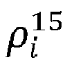
figure 6B an absolute value of such difference is calculated (block 1641b) as dual frequency estimated ionospheric error correction for the i-th satellite
- Then a
calculation 1642 of the correction difference, as the correction difference dii (difference block 1642b infigure 6B ) of the dual frequency estimated ionospheric error correction for the i-th satellite

figure 6B also here an absolute value of such difference is calculated (block 1642b) as absolute value. - Such correction difference dii is accumulated in a
step 1643 over the whole constellations of NS satellites S0-SNS-1 in view, and finally averaged in astep 1645, yielding a delta ionospheric error metric Δi, or range difference, for the current measurement epoch. Between theaccumulation step 1643 and the averaging step 1645 a check if new satellites are available in the constellation is performed. In the affirmative, it is returned to step 1641 to recalculate the correction difference dii with the new satellite constellations. Otherwise the averagingstep 1645 is performed. - The averaging step as detailed in
figure 6B implements the equation:
- The delta ionospheric error metric Δi is heavily affected by the high noise on IFLC pseudo-ranges

- In particular, as shown in
figure 6B , it is computed an ionospheric metric indicator It by filtering 1646 according to the recursive relation:
- If such ionospheric metric indicator It falls above a given threshold, as checked in a
checking block 1647. defined using practical case the solar storm state, or solar activity state, STM is declared, the solar correction condition active SR_ON is detected and signaled, and usage of IFLC pseudo-ranges inblock 14 to calculate the position PVT is performed. Otherwise, the normal state NRM is detected and signaled, i.e. the solar correction condition inactive SR_ON is detected and signaled, and the standard pseudo range measurements

position calculation 14. - AS mentioned in embodiments, modules 6-11 of the
GNSS receiver 100 can be implemented by software. Alsonavigation processing 12 as a whole, and in particular any or all ofmodules receiver 100. - The solutions disclosed herein have thus significant advantages with respect to the known solutions.
- Advantageously the solution here described represents a compensation approach for the position error caused by ionosphere approach which is independent from user location.
- The solution here described represents a compensation which is also real time, and hence can cope with sudden or unpredicted solar activity behaviour that could not be managed by standard compensation approaches (Klobuchar, SBAS)
- The solution here described represents a compensation approach which adaptively and seamlessly turns on and off depending on reception condition. Compared to prior solution, it can exploit IFLC only when really needed, avoiding to inject additional noise on solution or reduce measurement availability under benign solar condition or when user is located in a dense urban environment (where solar effects become less relevant compared to other environmental error factors like multipath).
- Of course, without prejudice to the principle of the invention, the details of construction and the embodiments may vary widely with respect to what has been described and illustrated herein purely by way of example, without thereby departing from the scope of the present invention, as defined by the ensuing claims.
Claims (8)
- Method for performing a correction of a ionospheric error affecting pseudo-ranges measurements in a GNSS receiver (100) receiving a plurality of satellite signals (s0,...,sNS-1) from a plurality of satellites (S0-SNS-1) of the constellation of satellites,comprising in a navigation processing procedure performed at a GNSS receiver (100),receiving pseudo range measurements(
 performing a correction procedure of said pseudo-range measurements (
 compensating (13) said pseudo-range measurements (

 applying (15) to said corrected pseudo-range measurements (
 performing a position calculation operation (11, 14) processing said corrected pseudo-range measurements (
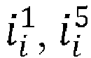 whereinsaid applying (15) to said corrected pseudo-ranges (
 comprisingperforming one or more checking operations (161, 162, 163, 164) enabling (SR_ON) performing (16) a Ionosphere Free Linear Combination on said pseudo-ranges measurements (
 otherwise performing (17) a standard ionospheric error correction (if) derived from GNSS navigation data, in particular by Klobuchar/Nequick models and/or SBAS, supplying the correspondingly standard ionospheric corrected pseudo-range measurements (
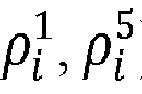 said performing one or more checking operations (161, 162, 163, 164) comprising evaluating (164) a solar activity (It) and enabling (SR_ON) performing said Ionospheric Free Linear Combination if the solar activity (It ) is above a given threshold.
 - A method according to claim 1 wherein said performing one or more checking operations (161, 162, 163, 164) further comprises performing, prior to said evaluating (164) a solar activity (It) one or more operations (161, 162, 163) checking if the receiver (100) is in condition to measure correctly said solar activity.
- The method according to Claim 2, wherein said one or more operations (161, 162, 163) checking if the receiver (100) is in condition to measure correctly said solar activity, comprise one or more of:checking (161) if the latitude is below a latitude threshold,checking (162) if a day condition is occurring,checking (163) if the GNSS receiver (100) is in an urban environment.
- The method according to Claim 3, wherein said performing one or more checking operations (161, 162, 163, 164) comprise a sequence of the operations:checking (161) if the latitude is below a latitude threshold,checking (162) if a day condition is occurring,checking (163) if the GNSS receiver (100) is in an urban environmentevaluating (164) a solar activity (It) and enabling (SR_ON) performing said Ionospheric Free Linear Combination if the solar activity (It ) is above a given threshold,each of said operations (161, 162, 163) enabling the execution of the following operation (162, 163, 164) in the sequence.
- The method according any of the previous Claims, wherein said evaluating (164) a solar activity (It) and enabling (SR_ON) performing said Ionospheric Free Linear Combination if the solar activity (It ) is above a given threshold comprisesreceiving a as input the pseudo range (

 calculating (1641) a dual frequency estimated ionospheric error correction for a given (i-th) satellite (

 calculating (1642) of a correction difference dii as the difference (1642b) of the dual frequency estimated ionospheric error correction for the i-th satellite (
 accumulating 1643 said correction difference (dii ) over the whole constellation of (NS) satellites S0-SNS-1 in view and averaging (1645) over the number (NS) of satellites S0-SNS-1 in view, yielding a delta ionospheric error metric (Δi), in particular between said accumulation step (1643) and averaging step (1645) checking (1644) check if new satellites are available, in the affirmative returning to the step of calculating (1641) a dual frequency estimated ionospheric error correction, otherwise performing the averaging step (1645),low pass filtering (1646), in particular by a IIR filter, said delta ionospheric error metric (Δi) obtaining an ionospheric metric solar activity indicator (It ),checking (1647) if said ionospheric metric solar activity indicator (It ) falls above a given threshold (ITH ), in the affirmative enabling (SR_ON) performing (16) a Ionosphere Free Linear Combination on said pseudo-ranges measurements (


- The method according any of the previous Claims, wherein said checking (163) if the GNSS receiver (100) is in an urban environment comprises
inputting the standard pseudo range measurements (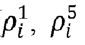


- Receiver apparatus configured to perform the method of any of Claims 1 to 6.
- Computer program product directly loadable into the internal memory of a digital computer, comprising software code portions for performing the steps of the method of any of Claims 1 to 6.
Applications Claiming Priority (1)
| Application Number | Priority Date | Filing Date | Title |
|---|---|---|---|
| IT102022000021036A IT202200021036A1 (en) | 2022-10-12 | 2022-10-12 | PROCEDURE FOR PERFORMING A CORRECTION OF AN IONOSPHERIC ERROR AFFECTING PSEUDO-RANGE MEASUREMENTS IN A GNSS RECEIVER, CORRESPONDING RECEIVER EQUIPMENT AND COMPUTER PRODUCT |
Publications (2)
| Publication Number | Publication Date |
|---|---|
| EP4354181A1 true EP4354181A1 (en) | 2024-04-17 |
| EP4354181B1 EP4354181B1 (en) | 2026-03-11 |
Family
ID=84462864
Family Applications (1)
| Application Number | Title | Priority Date | Filing Date |
|---|---|---|---|
| EP23199224.9A Active EP4354181B1 (en) | 2022-10-12 | 2023-09-22 | A method for performing a correction of a ionospheric error affecting pseudo-ranges measurements in a gnss receiver, corresponding receiver apparatus and computer program product |
Country Status (3)
| Country | Link |
|---|---|
| US (1) | US12613344B2 (en) |
| EP (1) | EP4354181B1 (en) |
| IT (1) | IT202200021036A1 (en) |
Families Citing this family (2)
| Publication number | Priority date | Publication date | Assignee | Title |
|---|---|---|---|---|
| CN119544028A (en) * | 2024-08-06 | 2025-02-28 | 陕西晶格时空航天技术有限公司 | A high-precision time synchronization system, method and application thereof |
| CN119716907B (en) * | 2024-12-06 | 2026-05-12 | 浙江吉利控股集团有限公司 | Correction method, device and equipment for transmission data of satellite |
Citations (3)
| Publication number | Priority date | Publication date | Assignee | Title |
|---|---|---|---|---|
| WO2015020552A1 (en) * | 2013-08-07 | 2015-02-12 | Llc "Topcon Positioning Systems" | Mitigation of scintillations in signals of global navigation satellite systems caused by ionospheric irregularities |
| WO2016034252A1 (en) * | 2014-09-05 | 2016-03-10 | Fugro Intersite B.V. | Ionospheric scintillation prediction |
| WO2022039879A1 (en) * | 2020-08-20 | 2022-02-24 | Qualcomm Incorporated | Multi-frequency real-time kinematic (rtk) measurements for global navigation satellite system (gnss) receivers |
Family Cites Families (6)
| Publication number | Priority date | Publication date | Assignee | Title |
|---|---|---|---|---|
| WO2007032947A1 (en) * | 2005-09-09 | 2007-03-22 | Trimble Navigation Limited | Ionosphere modeling apparatus and methods |
| US9488735B2 (en) * | 2011-03-23 | 2016-11-08 | Furuno Electric Co., Ltd. | Positioning apparatus, GNSS receiver, information terminal device, positioning method and program |
| US9784846B2 (en) * | 2013-08-21 | 2017-10-10 | Samsung Electronics Co., Ltd. | System, method, and apparatus for compensating for ionospheric delay in a multi constellation single radio frequency path GNSS receiver |
| EP3106897A1 (en) * | 2015-06-19 | 2016-12-21 | Centre National d'Etudes Spatiales | Gnss receiver with an on-board capability to implement an optimal error correction mode |
| KR101811760B1 (en) * | 2015-12-30 | 2017-12-22 | 순천향대학교 산학협력단 | Apparatus and method for ionospheric anomaly monitoring using kullback-leibler divergence metric based on gbas ground system |
| IT202300005820A1 (en) | 2023-03-27 | 2024-09-27 | St Microelectronics Int Nv | PROCEDURE FOR PERFORMING A CORRECTION OF AN IONOSPHERIC ERROR AFFECTING PSEUDO-RANGE MEASUREMENTS IN A GNSS RECEIVER, CORRESPONDING RECEIVER EQUIPMENT AND COMPUTER PRODUCT |
-
2022
- 2022-10-12 IT IT102022000021036A patent/IT202200021036A1/en unknown
-
2023
- 2023-09-22 EP EP23199224.9A patent/EP4354181B1/en active Active
- 2023-10-04 US US18/481,147 patent/US12613344B2/en active Active
Patent Citations (3)
| Publication number | Priority date | Publication date | Assignee | Title |
|---|---|---|---|---|
| WO2015020552A1 (en) * | 2013-08-07 | 2015-02-12 | Llc "Topcon Positioning Systems" | Mitigation of scintillations in signals of global navigation satellite systems caused by ionospheric irregularities |
| WO2016034252A1 (en) * | 2014-09-05 | 2016-03-10 | Fugro Intersite B.V. | Ionospheric scintillation prediction |
| WO2022039879A1 (en) * | 2020-08-20 | 2022-02-24 | Qualcomm Incorporated | Multi-frequency real-time kinematic (rtk) measurements for global navigation satellite system (gnss) receivers |
Also Published As
| Publication number | Publication date |
|---|---|
| IT202200021036A1 (en) | 2024-04-12 |
| EP4354181B1 (en) | 2026-03-11 |
| US12613344B2 (en) | 2026-04-28 |
| US20240134056A1 (en) | 2024-04-25 |
Similar Documents
| Publication | Publication Date | Title |
|---|---|---|
| US8456353B2 (en) | Method and system for determining clock corrections | |
| US6531981B1 (en) | Global augmentation to global positioning system | |
| US7986266B2 (en) | Method and system for selecting optimal satellites in view | |
| US7800530B2 (en) | Method and system for providing assistance data for A-GPS location of handsets in wireless networks | |
| EP3115807B1 (en) | Gnss receiver with an on-board capability to implement an optimal error correction mode | |
| US12117539B2 (en) | Inter-frequency signal aiding for tracking satellite navigation signals | |
| US7928903B2 (en) | Method and system for selecting optimal satellites for A-GPS location of handsets in wireless networks | |
| CN111801597B (en) | Self-assisted fast acquisition and first fix for standalone GNSS receivers | |
| US8125377B2 (en) | System and method for determining the location of a mobile device | |
| CN105607077A (en) | Spaceborne dual-mode quad-frequency GNSS navigation receiver | |
| EP4354181B1 (en) | A method for performing a correction of a ionospheric error affecting pseudo-ranges measurements in a gnss receiver, corresponding receiver apparatus and computer program product | |
| US20240329259A1 (en) | Method for performing a correction of an ionospheric error affecting pseudo-ranges measurements in a gnss receiver, corresponding receiver apparatus and computer program product | |
| US20140077992A1 (en) | Gnss system and method using unbiased code phase tracking with interleaved pseudo-random code | |
| WO2010080675A2 (en) | Method and system for selecting optimal satellites for a-gps location of handsets in wireless networks | |
| US9250330B2 (en) | Method and system for selecting optimal satellites for A-GPS location of handsets in wireless networks | |
| CN117872405A (en) | Method and receiver device for performing correction for ionospheric errors | |
| CN118707549A (en) | Method for performing ionospheric error correction, and GNSS receiver device | |
| Riley et al. | Impact of propagation mechanisms on global navigation satellite system performance |
Legal Events
| Date | Code | Title | Description |
|---|---|---|---|
| PUAI | Public reference made under article 153(3) epc to a published international application that has entered the european phase |
Free format text: ORIGINAL CODE: 0009012 |
|
| STAA | Information on the status of an ep patent application or granted ep patent |
Free format text: STATUS: THE APPLICATION HAS BEEN PUBLISHED |
|
| AK | Designated contracting states |
Kind code of ref document: A1 Designated state(s): AL AT BE BG CH CY CZ DE DK EE ES FI FR GB GR HR HU IE IS IT LI LT LU LV MC ME MK MT NL NO PL PT RO RS SE SI SK SM TR |
|
| STAA | Information on the status of an ep patent application or granted ep patent |
Free format text: STATUS: REQUEST FOR EXAMINATION WAS MADE |
|
| 17P | Request for examination filed |
Effective date: 20241011 |
|
| RBV | Designated contracting states (corrected) |
Designated state(s): AL AT BE BG CH CY CZ DE DK EE ES FI FR GB GR HR HU IE IS IT LI LT LU LV MC ME MK MT NL NO PL PT RO RS SE SI SK SM TR |
|
| GRAP | Despatch of communication of intention to grant a patent |
Free format text: ORIGINAL CODE: EPIDOSNIGR1 |
|
| STAA | Information on the status of an ep patent application or granted ep patent |
Free format text: STATUS: GRANT OF PATENT IS INTENDED |
|
| INTG | Intention to grant announced |
Effective date: 20251022 |
|
| GRAS | Grant fee paid |
Free format text: ORIGINAL CODE: EPIDOSNIGR3 |
|
| GRAA | (expected) grant |
Free format text: ORIGINAL CODE: 0009210 |
|
| STAA | Information on the status of an ep patent application or granted ep patent |
Free format text: STATUS: THE PATENT HAS BEEN GRANTED |
|
| AK | Designated contracting states |
Kind code of ref document: B1 Designated state(s): AL AT BE BG CH CY CZ DE DK EE ES FI FR GB GR HR HU IE IS IT LI LT LU LV MC ME MK MT NL NO PL PT RO RS SE SI SK SM TR |
|
| REG | Reference to a national code |
Ref country code: CH Ref legal event code: F10 Free format text: ST27 STATUS EVENT CODE: U-0-0-F10-F00 (AS PROVIDED BY THE NATIONAL OFFICE) Effective date: 20260311 Ref country code: GB Ref legal event code: FG4D |
|
| REG | Reference to a national code |
Ref country code: DE Ref legal event code: R096 Ref document number: 602023013281 Country of ref document: DE |
|
| REG | Reference to a national code |
Ref country code: IE Ref legal event code: FG4D |
|
| PG25 | Lapsed in a contracting state [announced via postgrant information from national office to epo] |
Ref country code: RS Free format text: LAPSE BECAUSE OF FAILURE TO SUBMIT A TRANSLATION OF THE DESCRIPTION OR TO PAY THE FEE WITHIN THE PRESCRIBED TIME-LIMIT Effective date: 20260611 |
|
| PG25 | Lapsed in a contracting state [announced via postgrant information from national office to epo] |
Ref country code: ES Free format text: LAPSE BECAUSE OF FAILURE TO SUBMIT A TRANSLATION OF THE DESCRIPTION OR TO PAY THE FEE WITHIN THE PRESCRIBED TIME-LIMIT Effective date: 20260311 |
|
| PG25 | Lapsed in a contracting state [announced via postgrant information from national office to epo] |
Ref country code: GR Free format text: LAPSE BECAUSE OF FAILURE TO SUBMIT A TRANSLATION OF THE DESCRIPTION OR TO PAY THE FEE WITHIN THE PRESCRIBED TIME-LIMIT Effective date: 20260612 |
|
| REG | Reference to a national code |
Ref country code: LT Ref legal event code: MG9D |
|
| PG25 | Lapsed in a contracting state [announced via postgrant information from national office to epo] |
Ref country code: LT Free format text: LAPSE BECAUSE OF FAILURE TO SUBMIT A TRANSLATION OF THE DESCRIPTION OR TO PAY THE FEE WITHIN THE PRESCRIBED TIME-LIMIT Effective date: 20260311 |
|
| PG25 | Lapsed in a contracting state [announced via postgrant information from national office to epo] |
Ref country code: NO Free format text: LAPSE BECAUSE OF FAILURE TO SUBMIT A TRANSLATION OF THE DESCRIPTION OR TO PAY THE FEE WITHIN THE PRESCRIBED TIME-LIMIT Effective date: 20260611 |
|
| PG25 | Lapsed in a contracting state [announced via postgrant information from national office to epo] |
Ref country code: FI Free format text: LAPSE BECAUSE OF FAILURE TO SUBMIT A TRANSLATION OF THE DESCRIPTION OR TO PAY THE FEE WITHIN THE PRESCRIBED TIME-LIMIT Effective date: 20260311 Ref country code: SE Free format text: LAPSE BECAUSE OF FAILURE TO SUBMIT A TRANSLATION OF THE DESCRIPTION OR TO PAY THE FEE WITHIN THE PRESCRIBED TIME-LIMIT Effective date: 20260311 |
|
| REG | Reference to a national code |
Ref country code: NL Ref legal event code: MP Effective date: 20260311 |
|
| PG25 | Lapsed in a contracting state [announced via postgrant information from national office to epo] |
Ref country code: HR Free format text: LAPSE BECAUSE OF FAILURE TO SUBMIT A TRANSLATION OF THE DESCRIPTION OR TO PAY THE FEE WITHIN THE PRESCRIBED TIME-LIMIT Effective date: 20260311 |
|
| PG25 | Lapsed in a contracting state [announced via postgrant information from national office to epo] |
Ref country code: LV Free format text: LAPSE BECAUSE OF FAILURE TO SUBMIT A TRANSLATION OF THE DESCRIPTION OR TO PAY THE FEE WITHIN THE PRESCRIBED TIME-LIMIT Effective date: 20260311 |
|
| PG25 | Lapsed in a contracting state [announced via postgrant information from national office to epo] |
Ref country code: BG Free format text: LAPSE BECAUSE OF FAILURE TO SUBMIT A TRANSLATION OF THE DESCRIPTION OR TO PAY THE FEE WITHIN THE PRESCRIBED TIME-LIMIT Effective date: 20260311 |