EP4354179A1 - System and method for determining a distance between networked electronic devices each comprising a loudspeaker and a microphone - Google Patents
System and method for determining a distance between networked electronic devices each comprising a loudspeaker and a microphone Download PDFInfo
- Publication number
- EP4354179A1 EP4354179A1 EP22201258.5A EP22201258A EP4354179A1 EP 4354179 A1 EP4354179 A1 EP 4354179A1 EP 22201258 A EP22201258 A EP 22201258A EP 4354179 A1 EP4354179 A1 EP 4354179A1
- Authority
- EP
- European Patent Office
- Prior art keywords
- sound signal
- electronic device
- measuring wave
- networked electronic
- wave
- Prior art date
- Legal status (The legal status is an assumption and is not a legal conclusion. Google has not performed a legal analysis and makes no representation as to the accuracy of the status listed.)
- Granted
Links
Images


Classifications
-
- G—PHYSICS
- G01—MEASURING; TESTING
- G01S—RADIO DIRECTION-FINDING; RADIO NAVIGATION; DETERMINING DISTANCE OR VELOCITY BY USE OF RADIO WAVES; LOCATING OR PRESENCE-DETECTING BY USE OF THE REFLECTION OR RERADIATION OF RADIO WAVES; ANALOGOUS ARRANGEMENTS USING OTHER WAVES
- G01S15/00—Systems using the reflection or reradiation of acoustic waves, e.g. sonar systems
- G01S15/74—Systems using reradiation of acoustic waves, e.g. IFF, i.e. identification of friend or foe
-
- G—PHYSICS
- G01—MEASURING; TESTING
- G01S—RADIO DIRECTION-FINDING; RADIO NAVIGATION; DETERMINING DISTANCE OR VELOCITY BY USE OF RADIO WAVES; LOCATING OR PRESENCE-DETECTING BY USE OF THE REFLECTION OR RERADIATION OF RADIO WAVES; ANALOGOUS ARRANGEMENTS USING OTHER WAVES
- G01S5/00—Position-fixing by co-ordinating two or more direction or position line determinations; Position-fixing by co-ordinating two or more distance determinations
- G01S5/18—Position-fixing by co-ordinating two or more direction or position line determinations; Position-fixing by co-ordinating two or more distance determinations using ultrasonic, sonic or infrasonic waves
-
- G—PHYSICS
- G01—MEASURING; TESTING
- G01S—RADIO DIRECTION-FINDING; RADIO NAVIGATION; DETERMINING DISTANCE OR VELOCITY BY USE OF RADIO WAVES; LOCATING OR PRESENCE-DETECTING BY USE OF THE REFLECTION OR RERADIATION OF RADIO WAVES; ANALOGOUS ARRANGEMENTS USING OTHER WAVES
- G01S11/00—Systems for determining distance or velocity not using reflection or reradiation
- G01S11/14—Systems for determining distance or velocity not using reflection or reradiation using ultrasonic, sonic or infrasonic waves
-
- G—PHYSICS
- G01—MEASURING; TESTING
- G01S—RADIO DIRECTION-FINDING; RADIO NAVIGATION; DETERMINING DISTANCE OR VELOCITY BY USE OF RADIO WAVES; LOCATING OR PRESENCE-DETECTING BY USE OF THE REFLECTION OR RERADIATION OF RADIO WAVES; ANALOGOUS ARRANGEMENTS USING OTHER WAVES
- G01S7/00—Details of systems according to groups G01S13/00, G01S15/00, G01S17/00
- G01S7/003—Transmission of data between radar, sonar or lidar systems and remote stations
-
- G—PHYSICS
- G01—MEASURING; TESTING
- G01S—RADIO DIRECTION-FINDING; RADIO NAVIGATION; DETERMINING DISTANCE OR VELOCITY BY USE OF RADIO WAVES; LOCATING OR PRESENCE-DETECTING BY USE OF THE REFLECTION OR RERADIATION OF RADIO WAVES; ANALOGOUS ARRANGEMENTS USING OTHER WAVES
- G01S15/00—Systems using the reflection or reradiation of acoustic waves, e.g. sonar systems
- G01S15/02—Systems using the reflection or reradiation of acoustic waves, e.g. sonar systems using reflection of acoustic waves
- G01S15/06—Systems determining the position data of a target
- G01S15/08—Systems for measuring distance only
- G01S15/32—Systems for measuring distance only using transmission of continuous waves, whether amplitude-, frequency-, or phase-modulated, or unmodulated
- G01S15/36—Systems for measuring distance only using transmission of continuous waves, whether amplitude-, frequency-, or phase-modulated, or unmodulated with phase comparison between the received signal and the contemporaneously transmitted signal
-
- G—PHYSICS
- G01—MEASURING; TESTING
- G01S—RADIO DIRECTION-FINDING; RADIO NAVIGATION; DETERMINING DISTANCE OR VELOCITY BY USE OF RADIO WAVES; LOCATING OR PRESENCE-DETECTING BY USE OF THE REFLECTION OR RERADIATION OF RADIO WAVES; ANALOGOUS ARRANGEMENTS USING OTHER WAVES
- G01S7/00—Details of systems according to groups G01S13/00, G01S15/00, G01S17/00
- G01S7/52—Details of systems according to groups G01S13/00, G01S15/00, G01S17/00 of systems according to group G01S15/00
- G01S7/52004—Means for monitoring or calibrating
-
- G—PHYSICS
- G01—MEASURING; TESTING
- G01S—RADIO DIRECTION-FINDING; RADIO NAVIGATION; DETERMINING DISTANCE OR VELOCITY BY USE OF RADIO WAVES; LOCATING OR PRESENCE-DETECTING BY USE OF THE REFLECTION OR RERADIATION OF RADIO WAVES; ANALOGOUS ARRANGEMENTS USING OTHER WAVES
- G01S7/00—Details of systems according to groups G01S13/00, G01S15/00, G01S17/00
- G01S7/52—Details of systems according to groups G01S13/00, G01S15/00, G01S17/00 of systems according to group G01S15/00
- G01S7/539—Details of systems according to groups G01S13/00, G01S15/00, G01S17/00 of systems according to group G01S15/00 using analysis of echo signal for target characterisation; Target signature; Target cross-section
Definitions
- the present invention relates to determining a distance between networked electronic devices. Especially, it relates to determining such a distance using properties of sound emitted and received by the networked electronic devices using loudspeakers and microphones of the networked electronic devices.
- the inventors of the present invention have realized that there is a need for an additional method of determining a distance between a first device and a second device, especially for the case of determining a distance between devices of a system of devices mounted in a building.
- a method for determining a distance between a first networked electronic device and a second networked electronic device comprises emitting, using the first loudspeaker, a first sound signal.
- the first sound signal comprises a first measuring wave having a first frequency carried on a first carrier wave having a first carrier frequency.
- the first carrier frequency is higher than the first frequency.
- the method further comprises receiving, using the second microphone, the first sound signal.
- the method further comprises defining, at the second electronic device, a second sound signal.
- the second sound signal comprises a second measuring wave carried on a second carrier wave.
- the second measuring wave has the same frequency as the first measuring wave. Hence, the second measuring wave has the first frequency.
- the second carrier wave has a second carrier frequency different from the first carrier frequency.
- a phase of the second measuring wave is set such that it simulates a reflection of the first measuring wave on the second networked electronic device.
- the method further comprises emitting, using the second loudspeaker, the second sound signal.
- the method further comprises receiving, using the first microphone, the second sound signal.
- the method further comprises calculating the distance between the first networked electronic device and the second networked electronic device based on a phase shift between the emitted first measuring wave and the received second measuring wave.
- a distance between two devices each equipped with a loudspeaker and a microphone can be determined. This by looking at a phase shift of a low frequency periodic measuring wave carried on a sound-based carrier wave.
- the low frequency periodic measuring wave might even be below 20 Hz.
- the frequency of the measuring wave needs to be 3-160 Hz. That since the wavelength of the measuring wave needs to be longer than half the distance between the two devices.
- Most loudspeakers cannot reproduce waves having such low frequencies.
- the first and second carrier waves may have a carrier frequency in a range of 200-20 000 Hz.
- Defining the second sound signal may comprise setting the phase of the second measuring wave to be same as a phase of the first measuring wave of the by the second microphone received first sound signal.
- Setting the phase of the second measuring wave may comprises determining the phase of the second measuring wave based on a processing time of a circuitry at the second networked electronic device analyzing the first sound signal in order to determine the phase of the received first measuring wave.
- Defining and emitting the second sound signal may comprise emitting a candidate second sound signal; shifting, while listening with the second microphone, the phase of the second measuring wave of the candidate second sound signal until the phases of the received first measuring wave and the second measuring wave of the candidate second sound signal match up; and upon the phases of the received first measuring wave and the second measuring wave of the candidate second sound signal matching up, emitting the second sound signal as having the matched-up phase.
- a system for determining a distance between a first networked electronic device and a second networked electronic device comprises: the first networked electronic device having a first loudspeaker and a first microphone; and the second networked electronic device having a second loudspeaker and a second microphone.
- the first networked electronic device further comprises first circuitry configured to: define a first sound signal comprising a first measuring wave having a first frequency carried on a first carrier wave having a first carrier frequency being higher than the first frequency; and drive the first loudspeaker to emit the first sound signal.
- the second networked electronic device further comprises second circuitry configured to: analyze the first sound signal upon its registration by the second microphone; define a second sound signal comprising a second measuring wave having the first frequency carried on a second carrier wave having a second carrier frequency being higher than the first frequency and different from the first carrier frequency, wherein a phase of the second measuring wave is set such that it simulates a reflection of the first measuring wave of the first sound signal on the second networked electronic device; and drive the second loudspeaker to emit the second sound signal.
- the first circuitry of the first networked electronic device is further configured to: analyze the second sound signal upon its registration by the first microphone; determine a phase shift between the emitted first measuring wave and the received second measuring wave; and calculate the distance between the first networked electronic device and the second networked electronic device based on the determined phase shift.
- Fig. 1 illustrates a system 10 of networked electronic devices 100 mounted in a building 50.
- a networked electronic device is schematically illustrated in Fig. 2 .
- Each networked electronic device 100 has a loudspeaker 110 and a microphone 120.
- Examples of such networked electronic devices 100 are networked loudspeakers, networked monitoring cameras and/or networked access control devices.
- the networked electronic device 100 may comprise circuitry 130, a memory 140 and a communication module 150.
- the communication module 150 is configured to send and/or receive data via a communication network to which the networked electronic device 100 is connected.
- the circuitry 130 is configured to carry out overall control of functions and operations of the networked electronic device 100.
- the circuitry 130 may include a processor, such as a central processing unit (CPU), microcontroller, or microprocessor.
- the processor is configured to execute program code stored in the memory 140, in order to carry out functions and operations of the networked electronic device 100.
- the memory 140 may be one or more of a buffer, a flash memory, a hard drive, a removable medium, a volatile memory, a non-volatile memory, a random access memory (RAM), or another suitable device.
- the memory 140 may include a non-volatile memory for long term data storage and a volatile memory that functions as system memory for the networked electronic device 100.
- the memory 140 may exchange data with the circuitry 130, the loudspeaker 110, the microphone 120 and/or the communication module 150 over a data bus 160.
- Functions and operations of the networked electronic device 100 may be embodied in the form of executable logic routines (e.g., lines of code, software programs, etc.) that are stored on a non-transitory computer readable medium (e.g., the memory 140) of the networked electronic device 100 and are executed by the circuitry 130 (e.g., using the processor).
- the functions and operations of the networked electronic device 100 may be a stand-alone software application or form a part of a software application that carries out additional tasks related to the networked electronic device 100.
- the functions and operations may be considered a method that the networked electronic device 100 is configured to carry out.
- the functions and operations may be implemented in software, such functionality may as well be carried out via dedicated hardware or firmware, or some combination of hardware, firmware and/or software.
- distances between the different networked electronic devices 100 are to be determined.
- Fig. 3 schematically illustrates using properties of sound for determining a distance between two networked electronic devices 100a, 100b and Fig. 4 is a block diagram of a method for determining a distance between the first electronic device 100a and the second electronic device 100b.
- a first networked electronic devices 100a is instructed to emit S402, via its loudspeaker, a first sound signal 300 comprising a first measuring wave 310 having a first frequency carried on a first carrier wave 320 having a first carrier frequency.
- the first sound signal 300 is illustrated along the "Forward path" in Fig. 3 .
- a second networked electronic device 100b within earshot of the first sound signal 300, is set to, via its microphone, listen to the first sound signal 300. Hence, the second networked electronic device 100b is set to receive S404 the first sound signal.
- the second networked electronic device 100b Upon receipt of the first sound signal 300, the second networked electronic device 100b is set to, via its loudspeaker, emit S406 a second sound signal 350 having a second measuring wave 360.
- the second measuring wave 360 has the same first frequency as the first measuring wave 310 but carried on a second carrier wave 370 having a second carrier frequency different from the first carrier frequency.
- the second sound signal 350 is illustrated along the "Return path" in Fig. 3 .
- the second sound signal 350 may be differentiated from echoes of the first sound signal 300 from other structures.
- the second networked electronic device 100b is set to shift a phase of the second measuring wave 360 so that it simulates a reflection of the first measuring wave 310 on the second networked electronic device 100b. That is, the phase of the second measuring wave 360 is to be set to be same as a phase of the first measuring wave 320 at the second networked electronic device 100b.
- the second networked electronic device 100b is set to define the second sound signal 350 such that a phase of the second measuring wave 360 is set such that it simulates a reflection of the first measuring wave 310 on the second networked electronic device 100b.
- the second sound signal 350 may be defined using circuitry of the second networked electronic device 100b.
- the second networked electronic device 100b is set to answer with a second sound signal 350 comprising a second measuring wave 360 having the same phase as the first measuring wave 310 of the incoming first sound signal 300. That is, the second networked electronic device 100b is set to simulate a reflection of the first measuring wave 310. However, in order to distinguish the simulated reflection from real reflections on other structures, the second networked electronic device 100b is set to carry the second measuring wave 360 on a second carrier wave 370 having a carrier frequency different from the carrier frequency of the first sound signal 300.
- defining the second sound signal 350 comprises setting the phase of the second measuring wave 360 to be same as a phase of the first measuring wave 310 of the by the second microphone of the second networked electronic device 100b received first sound signal 300.
- Setting the phase of the second measuring wave 360 may comprise determining the phase of the second measuring wave 360 based on a processing time of a circuitry at the second networked electronic device 100b analyzing the first sound signal 300 in order to determine the phase of the received first measuring wave 310. Doing so the phase of the second measuring wave 360 can be timed with the phase of the received first measuring wave 310.
- defining and emitting the second sound signal 350 may comprise: i) emitting a candidate second sound signal, ii) shifting, while listening with the second microphone of the second networked electronic device 100b, the phase of the second measuring wave of the candidate second sound signal until the phases of the received first measuring wave 310 and the second measuring wave of the candidate second sound signal match up, and iii) upon the phases of the received first measuring wave 310 and the second measuring wave of the candidate second sound signal matching up, emitting the second sound signal 350 as having the matched-up phase.
- the first networked electronic device 100a is then set to, via its microphone 120a, listen to the second sound signal 350. Hence, the first networked electronic device 100a is set to receive S408 the second sound signal.
- a distance between the first networked electronic device 100a and the second networked electronic device 100b can then be determined based on a phase shift between the, at the first networked electronic device 100a, emitted first measuring wave 310 and the, at the first networked electronic device 100a, received second measuring wave 360. This since such a phase shift will depend on the distance between the first and second networked electronic devices 100a, 100b.
- the first frequency should be in the range of 160 Hz and 3.3 Hz.
- the frequency for the first and second carrier waves 320, 370 shall be higher than the first frequency, hence typically above 200 Hz.
- An upper limit for the frequency of the first and second carrier waves 320, 370 is typically 20 000 Hz.
- the first and second carrier waves 320, 370 are set to have different carrier frequencies. By using different carrier frequencies for the different carrier waves 320, 370 the second sound signal 350 may be differentiated from echoes of the first sound signal 300 from other structures in the building.
- an identity of the networked electronic devices 100 can be encoded by assigning a specific carrier frequency to a specific networked electronic device.
- the first and second sound signals 300, 350 are sinusoidal amplitude modulated signals. However, any periodic signal that can be carried by a carrier wave would work.
- both the first and the second networked electronic devices are fixedly mounted in the building.
- the first electronic device may be a portable electronic device, such as a mobile phone.
Landscapes
- Engineering & Computer Science (AREA)
- Radar, Positioning & Navigation (AREA)
- Remote Sensing (AREA)
- Physics & Mathematics (AREA)
- General Physics & Mathematics (AREA)
- Computer Networks & Wireless Communication (AREA)
- Acoustics & Sound (AREA)
- Measurement Of Velocity Or Position Using Acoustic Or Ultrasonic Waves (AREA)
- Circuit For Audible Band Transducer (AREA)
Abstract
Description
- The present invention relates to determining a distance between networked electronic devices. Especially, it relates to determining such a distance using properties of sound emitted and received by the networked electronic devices using loudspeakers and microphones of the networked electronic devices.
- In many applications there is a need to determine a distance between a first device and a second device. It is, e.g., known to perform distance measurements using different methods such as using a tape-measure, a laser-based range finder, or a sonar. The different methods have their pros and cons.
- The inventors of the present invention have realized that there is a need for an additional method of determining a distance between a first device and a second device, especially for the case of determining a distance between devices of a system of devices mounted in a building.
- In view of the above, it is an object of the present invention to provide a method of determining a distance between a first device and a second device.
- According to a first aspect a method for determining a distance between a first networked electronic device and a second networked electronic device is provided. The first networked electronic device has a first loudspeaker and a first microphone. The second networked electronic device has a second loudspeaker and a second microphone. The method comprises emitting, using the first loudspeaker, a first sound signal. The first sound signal comprises a first measuring wave having a first frequency carried on a first carrier wave having a first carrier frequency. The first carrier frequency is higher than the first frequency. The method further comprises receiving, using the second microphone, the first sound signal. The method further comprises defining, at the second electronic device, a second sound signal. The second sound signal comprises a second measuring wave carried on a second carrier wave. The second measuring wave has the same frequency as the first measuring wave. Hence, the second measuring wave has the first frequency. The second carrier wave has a second carrier frequency different from the first carrier frequency. A phase of the second measuring wave is set such that it simulates a reflection of the first measuring wave on the second networked electronic device. The method further comprises emitting, using the second loudspeaker, the second sound signal. The method further comprises receiving, using the first microphone, the second sound signal. The method further comprises calculating the distance between the first networked electronic device and the second networked electronic device based on a phase shift between the emitted first measuring wave and the received second measuring wave.
- In line with the above, the inventors have realized that by using properties of sound, a distance between two devices each equipped with a loudspeaker and a microphone can be determined. This by looking at a phase shift of a low frequency periodic measuring wave carried on a sound-based carrier wave. The low frequency periodic measuring wave might even be below 20 Hz. In order to determine distances in the range of 1 m to 50 m the frequency of the measuring wave needs to be 3-160 Hz. That since the wavelength of the measuring wave needs to be longer than half the distance between the two devices. Most loudspeakers cannot reproduce waves having such low frequencies. By using a carrier wave emitting a measuring wave having as low frequency as discussed above is provided for.
- The first and second carrier waves may have a carrier frequency in a range of 200-20 000 Hz.
- Defining the second sound signal may comprise setting the phase of the second measuring wave to be same as a phase of the first measuring wave of the by the second microphone received first sound signal.
- Setting the phase of the second measuring wave may comprises determining the phase of the second measuring wave based on a processing time of a circuitry at the second networked electronic device analyzing the first sound signal in order to determine the phase of the received first measuring wave.
- Defining and emitting the second sound signal may comprise emitting a candidate second sound signal; shifting, while listening with the second microphone, the phase of the second measuring wave of the candidate second sound signal until the phases of the received first measuring wave and the second measuring wave of the candidate second sound signal match up; and upon the phases of the received first measuring wave and the second measuring wave of the candidate second sound signal matching up, emitting the second sound signal as having the matched-up phase.
- According to a second aspect a system for determining a distance between a first networked electronic device and a second networked electronic device is provided. The system comprises: the first networked electronic device having a first loudspeaker and a first microphone; and the second networked electronic device having a second loudspeaker and a second microphone. The first networked electronic device further comprises first circuitry configured to: define a first sound signal comprising a first measuring wave having a first frequency carried on a first carrier wave having a first carrier frequency being higher than the first frequency; and drive the first loudspeaker to emit the first sound signal. The second networked electronic device further comprises second circuitry configured to: analyze the first sound signal upon its registration by the second microphone; define a second sound signal comprising a second measuring wave having the first frequency carried on a second carrier wave having a second carrier frequency being higher than the first frequency and different from the first carrier frequency, wherein a phase of the second measuring wave is set such that it simulates a reflection of the first measuring wave of the first sound signal on the second networked electronic device; and drive the second loudspeaker to emit the second sound signal. The first circuitry of the first networked electronic device is further configured to: analyze the second sound signal upon its registration by the first microphone; determine a phase shift between the emitted first measuring wave and the received second measuring wave; and calculate the distance between the first networked electronic device and the second networked electronic device based on the determined phase shift.
- The above-mentioned features of the method, when applicable, apply to this second aspect as well. In order to avoid undue repetition, reference is made to the above.
- A further scope of applicability will become apparent from the detailed description given below. However, it should be understood that the detailed description and specific examples are given by way of illustration only.
- It is to be understood that the terminology used herein is for purpose of describing particular embodiments only, and is not intended to be limiting. It must be noted that, as used in the specification and the appended claim, the articles "a," "an," "the," and "said" are intended to mean that there are one or more of the elements unless the context clearly dictates otherwise. Thus, for example, reference to "a unit" or "the unit" may include several devices, and the like. Furthermore, the words "comprising", "including", "containing" and similar wordings does not exclude other elements or steps.
- The above and other aspects will now be described in more detail, with reference to appended figures. The figures should not be considered limiting; instead they are used for explaining and understanding.
- As illustrated in the figures, the sizes of layers and regions may be exaggerated for illustrative purposes and, thus, are provided to illustrate the general structures. Like reference numerals refer to like elements throughout.
-
Fig. 1 schematically illustrates a system of networked electronic devices mounted in a building. -
Fig. 2 schematically illustrates a networked electronic device. -
Fig. 3 schematically illustrates a method of using properties of sound for determining a distance between two networked electronic devices. -
Fig. 4 is a block diagram of a method for determining a distance between the first electronic device and the second electronic device. - The present invention will now be described more fully hereinafter with reference to the accompanying drawings, in which currently preferred embodiments of the invention are shown. This invention may, however, be embodied in many different forms and should not be construed as limited to the embodiments set forth herein; rather, these embodiments are provided for thoroughness and completeness, and to fully convey the scope of the invention to the skilled person.
-
Fig. 1 illustrates asystem 10 of networkedelectronic devices 100 mounted in abuilding 50. Such a networked electronic device is schematically illustrated inFig. 2 . Each networkedelectronic device 100 has aloudspeaker 110 and amicrophone 120. Examples of such networkedelectronic devices 100 are networked loudspeakers, networked monitoring cameras and/or networked access control devices. In addition to theloudspeaker 110 and amicrophone 120, the networkedelectronic device 100 may comprisecircuitry 130, amemory 140 and acommunication module 150. Thecommunication module 150 is configured to send and/or receive data via a communication network to which the networkedelectronic device 100 is connected. Thecircuitry 130 is configured to carry out overall control of functions and operations of the networkedelectronic device 100. Thecircuitry 130 may include a processor, such as a central processing unit (CPU), microcontroller, or microprocessor. The processor is configured to execute program code stored in thememory 140, in order to carry out functions and operations of the networkedelectronic device 100. Thememory 140 may be one or more of a buffer, a flash memory, a hard drive, a removable medium, a volatile memory, a non-volatile memory, a random access memory (RAM), or another suitable device. In a typical arrangement, thememory 140 may include a non-volatile memory for long term data storage and a volatile memory that functions as system memory for the networkedelectronic device 100. Thememory 140 may exchange data with thecircuitry 130, theloudspeaker 110, themicrophone 120 and/or thecommunication module 150 over adata bus 160. Functions and operations of the networkedelectronic device 100 may be embodied in the form of executable logic routines (e.g., lines of code, software programs, etc.) that are stored on a non-transitory computer readable medium (e.g., the memory 140) of the networkedelectronic device 100 and are executed by the circuitry 130 (e.g., using the processor). Furthermore, the functions and operations of the networkedelectronic device 100 may be a stand-alone software application or form a part of a software application that carries out additional tasks related to the networkedelectronic device 100. The functions and operations may be considered a method that the networkedelectronic device 100 is configured to carry out. Also, while the functions and operations may be implemented in software, such functionality may as well be carried out via dedicated hardware or firmware, or some combination of hardware, firmware and/or software. - For some applications, such as during commissioning of the
system 10 of networkedelectronic devices 100, distances between the different networkedelectronic devices 100 are to be determined. Various methods for determining distance exist as of today, e.g., tape-measure, a laser-based range finder, or a sonar. However, none of them are optimal for determining a distance between two networkedelectronic devises 100 being mounted in abuilding 50. - The inventors of the present invention have realized that properties of sound can be used in determining a distance between two networked
electronic devices 100a, 100b each equipped with a loudspeaker and a microphone. This will now be discussed in connection withFigs. 3 and4 .Fig. 3 schematically illustrates using properties of sound for determining a distance between two networkedelectronic devices 100a, 100b andFig. 4 is a block diagram of a method for determining a distance between the firstelectronic device 100a and the second electronic device 100b. - A first networked
electronic devices 100a is instructed to emit S402, via its loudspeaker, afirst sound signal 300 comprising afirst measuring wave 310 having a first frequency carried on afirst carrier wave 320 having a first carrier frequency. Thefirst sound signal 300 is illustrated along the "Forward path" inFig. 3 . - A second networked electronic device 100b, within earshot of the
first sound signal 300, is set to, via its microphone, listen to thefirst sound signal 300. Hence, the second networked electronic device 100b is set to receive S404 the first sound signal. - Upon receipt of the
first sound signal 300, the second networked electronic device 100b is set to, via its loudspeaker, emit S406 asecond sound signal 350 having asecond measuring wave 360. Thesecond measuring wave 360 has the same first frequency as thefirst measuring wave 310 but carried on asecond carrier wave 370 having a second carrier frequency different from the first carrier frequency. Thesecond sound signal 350 is illustrated along the "Return path" inFig. 3 . By using the second carrier frequency different from the first carrier frequency thesecond sound signal 350 may be differentiated from echoes of thefirst sound signal 300 from other structures. - Further, the second networked electronic device 100b is set to shift a phase of the
second measuring wave 360 so that it simulates a reflection of thefirst measuring wave 310 on the second networked electronic device 100b. That is, the phase of thesecond measuring wave 360 is to be set to be same as a phase of thefirst measuring wave 320 at the second networked electronic device 100b. Hence, the second networked electronic device 100b is set to define thesecond sound signal 350 such that a phase of thesecond measuring wave 360 is set such that it simulates a reflection of thefirst measuring wave 310 on the second networked electronic device 100b. Thesecond sound signal 350 may be defined using circuitry of the second networked electronic device 100b. Hence, the second networked electronic device 100b is set to answer with asecond sound signal 350 comprising asecond measuring wave 360 having the same phase as thefirst measuring wave 310 of the incomingfirst sound signal 300. That is, the second networked electronic device 100b is set to simulate a reflection of thefirst measuring wave 310. However, in order to distinguish the simulated reflection from real reflections on other structures, the second networked electronic device 100b is set to carry thesecond measuring wave 360 on asecond carrier wave 370 having a carrier frequency different from the carrier frequency of thefirst sound signal 300. In other words, defining thesecond sound signal 350 comprises setting the phase of thesecond measuring wave 360 to be same as a phase of thefirst measuring wave 310 of the by the second microphone of the second networked electronic device 100b receivedfirst sound signal 300. Setting the phase of thesecond measuring wave 360 may comprise determining the phase of thesecond measuring wave 360 based on a processing time of a circuitry at the second networked electronic device 100b analyzing thefirst sound signal 300 in order to determine the phase of the received first measuringwave 310. Doing so the phase of thesecond measuring wave 360 can be timed with the phase of the received first measuringwave 310. Alternatively, or in combination, defining and emitting thesecond sound signal 350 may comprise: i) emitting a candidate second sound signal, ii) shifting, while listening with the second microphone of the second networked electronic device 100b, the phase of the second measuring wave of the candidate second sound signal until the phases of the received first measuringwave 310 and the second measuring wave of the candidate second sound signal match up, and iii) upon the phases of the received first measuringwave 310 and the second measuring wave of the candidate second sound signal matching up, emitting thesecond sound signal 350 as having the matched-up phase. - The first networked
electronic device 100a is then set to, via its microphone 120a, listen to thesecond sound signal 350. Hence, the first networkedelectronic device 100a is set to receive S408 the second sound signal. - A distance between the first networked
electronic device 100a and the second networked electronic device 100b can then be determined based on a phase shift between the, at the first networkedelectronic device 100a, emitted first measuringwave 310 and the, at the first networkedelectronic device 100a, received second measuringwave 360. This since such a phase shift will depend on the distance between the first and second networkedelectronic devices 100a, 100b. The distance, D, between the first and second networkedelectronic devices 100a, 100b can be expressed as:
- where ΔΦ is the phase shift [expressed in radians] and λ is the wavelength of the measuring wave defined as:
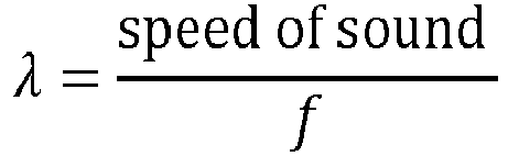
- where f is the frequency of the measuring waves 310, 360, i.e., the first frequency discussed above. This under the assumption that the distance between the first and second networked
electronic devices 100a, 100b is within half a wavelength. Hence, the distance D between the first networkedelectronic device 100a and the second networked electronic device 100b is calculated S410 based on a phase shift between the emitted first measuringwave 310 and the received second measuringwave 360. The calculating S410 is preferably made by circuitry of the first networkedelectronic device 100a. However, the calculating S410 can be made at any other device having computational capabilities and being connected to the first networkedelectronic device 100a so that the phase shift or information for calculating the phase shift may be communicated thereto. - Assuming the workable range for the distance one would want to measure is between 1 m and 50 m, then the first frequency should be in the range of 160 Hz and 3.3 Hz. The frequency for the first and
second carrier waves second carrier waves second carrier waves different carrier waves second sound signal 350 may be differentiated from echoes of thefirst sound signal 300 from other structures in the building. Further, an identity of the networkedelectronic devices 100 can be encoded by assigning a specific carrier frequency to a specific networked electronic device. Typically, the first and second sound signals 300, 350 are sinusoidal amplitude modulated signals. However, any periodic signal that can be carried by a carrier wave would work. - The person skilled in the art realizes that the present invention by no means is limited to what is explicitly described above. On the contrary, many modifications and variations are possible within the scope of the appended claims.
- For example, in some applications both the first and the second networked electronic devices are fixedly mounted in the building. In other applications the first electronic device may be a portable electronic device, such as a mobile phone.
- Additionally, variations can be understood and effected by the skilled person in practicing the claimed invention, from a study of the drawings, the disclosure, and the appended claims.
Claims (9)
- A method for determining a distance between a first networked electronic device (100a) having a first loudspeaker and a first microphone and a second networked electronic device (100b) having a second loudspeaker and a second microphone, the method comprising:emitting (S402), using the first loudspeaker, a first sound signal (300) comprising a first measuring wave (310) having a first frequency carried on a first carrier wave (320) having a first carrier frequency being higher than the first frequency;receiving (S404), using the second microphone, the first sound signal (300);defining, at the second electronic device (100b), a second sound signal (350) comprising a second measuring wave (360) having the first frequency carried on a second carrier wave (370) having a second carrier frequency different from the first carrier frequency, wherein a phase of the second measuring wave (360) is set such that it simulates a reflection of the first measuring wave (310) on the second networked electronic device (100b);emitting (S406), using the second loudspeaker, the second sound signal (350);receiving (S408), using the first microphone, the second sound signal (350); andcalculating (S410) the distance between the first networked electronic device (100a) and the second networked electronic device (100b) based on a phase shift between the emitted first measuring wave (310) and the received second measuring wave (360).
- The method according to claim 1, wherein the first frequency of the first and second measuring waves (310, 360) is in a range of 3-160 Hz.
- The method according to claim 1 or 2, wherein the first and second carrier waves (320, 370) have a carrier frequency in a range of 200-20 000 Hz.
- The method according to any one of claims 1-3, wherein defining the second sound signal (350) comprises setting the phase of the second measuring wave (360) to be same as a phase of the first measuring wave (310) of the by the second microphone received first sound signal (300).
- The method according to claim 4, wherein setting the phase of the second measuring wave (360) comprises determining the phase of the second measuring wave (360) based on a processing time of a circuitry at the second networked electronic device analyzing the first sound signal (300) in order to determine the phase of the received first measuring wave (310).
- The method according to claim 4, wherein defining and emitting the second sound signal (350) comprises:emitting a candidate second sound signal,shifting, while listening with the second microphone, the phase of the second measuring wave of the candidate second sound signal until the phases of the received first measuring wave (310) and the second measuring wave of the candidate second sound signal match up, andupon the phases of the received first measuring wave (310) and the second measuring wave of the candidate second sound signal matching up, emitting the second sound signal (350) as having the matched-up phase.
- A system for determining a distance between a first networked electronic device (100a) and a second networked electronic device (100b), the system comprising:the first networked electronic device (100a) having a first loudspeaker and a first microphone; andthe second networked electronic device (100b) having a second loudspeaker and a second microphone,wherein the first networked electronic device (100a) further comprises first circuitry configured to:define a first sound signal (300) comprising a first measuring wave (310) having a first frequency carried on a first carrier wave (320) having a first carrier frequency being higher than the first frequency, anddrive the first loudspeaker to emit the first sound signal (300);wherein the second networked electronic device (100b) further comprises second circuitry configured to:analyze the first sound signal (300) upon its registration by the second microphone,define a second sound signal (350) comprising a second measuring wave (360) having the first frequency carried on a second carrier wave (370) having a second carrier frequency being higher than the first frequency and different from the first carrier frequency, wherein a phase of the second measuring wave (360) is set such that it simulates a reflection of the first measuring wave (310) of the first sound signal (300) on the second networked electronic device (100b), anddrive the second loudspeaker to emit the second sound signal (350);wherein the first circuitry of the first networked electronic device (100a) is further configured to:analyze the second sound signal (350) upon its registration by the first microphone,determine a phase shift between the emitted first measuring wave (310) and the received second measuring wave (360), andcalculate the distance between the first networked electronic device (100a) and the second networked electronic device (100b) based on the determined phase shift.
- The system according to claim 7, wherein the first frequency of the first and second measuring waves (310, 360) is in a range of 3-160 Hz.
- The system according to claim 7 or 8, wherein the first and second carrier waves (320, 370) have a carrier frequency in a range of 200-20 000 Hz.
Priority Applications (6)
| Application Number | Priority Date | Filing Date | Title |
|---|---|---|---|
| EP22201258.5A EP4354179B1 (en) | 2022-10-13 | 2022-10-13 | System and method for determining a distance between networked electronic devices each comprising a loudspeaker and a microphone |
| KR1020230092897A KR102968168B1 (en) | 2022-10-13 | 2023-07-18 | System and method for determining a distance between networked electronic devices each comprising a loudspeaker and a microphone |
| TW112128742A TWI915663B (en) | 2022-10-13 | 2023-08-01 | System and method for determining a distance between networked electronic devices each comprising a loudspeaker and a microphone |
| CN202311272168.3A CN117890897B (en) | 2022-10-13 | 2023-09-28 | System and method for determining distance between networked electronic devices |
| JP2023172498A JP7742869B2 (en) | 2022-10-13 | 2023-10-04 | Systems and methods for determining distance between networked electronic devices each equipped with a loudspeaker and a microphone |
| US18/481,562 US12386024B2 (en) | 2022-10-13 | 2023-10-05 | System and method for determining a distance between networked electronic devices each comprising a loudspeaker and a microphone |
Applications Claiming Priority (1)
| Application Number | Priority Date | Filing Date | Title |
|---|---|---|---|
| EP22201258.5A EP4354179B1 (en) | 2022-10-13 | 2022-10-13 | System and method for determining a distance between networked electronic devices each comprising a loudspeaker and a microphone |
Publications (3)
| Publication Number | Publication Date |
|---|---|
| EP4354179A1 true EP4354179A1 (en) | 2024-04-17 |
| EP4354179C0 EP4354179C0 (en) | 2025-07-23 |
| EP4354179B1 EP4354179B1 (en) | 2025-07-23 |
Family
ID=83898489
Family Applications (1)
| Application Number | Title | Priority Date | Filing Date |
|---|---|---|---|
| EP22201258.5A Active EP4354179B1 (en) | 2022-10-13 | 2022-10-13 | System and method for determining a distance between networked electronic devices each comprising a loudspeaker and a microphone |
Country Status (5)
| Country | Link |
|---|---|
| US (1) | US12386024B2 (en) |
| EP (1) | EP4354179B1 (en) |
| JP (1) | JP7742869B2 (en) |
| CN (1) | CN117890897B (en) |
| TW (1) | TWI915663B (en) |
Cited By (1)
| Publication number | Priority date | Publication date | Assignee | Title |
|---|---|---|---|---|
| US12386024B2 (en) * | 2022-10-13 | 2025-08-12 | Axis Ab | System and method for determining a distance between networked electronic devices each comprising a loudspeaker and a microphone |
Citations (2)
| Publication number | Priority date | Publication date | Assignee | Title |
|---|---|---|---|---|
| US4219885A (en) * | 1964-09-08 | 1980-08-26 | The United States Of America As Represented By The Secretary Of The Navy | Sonar target simulator |
| US20140179432A1 (en) * | 1998-09-16 | 2014-06-26 | Dialware Inc. | Interactive toys |
Family Cites Families (23)
| Publication number | Priority date | Publication date | Assignee | Title |
|---|---|---|---|---|
| US3078460A (en) * | 1958-09-02 | 1963-02-19 | Cubic Corp | Electronic surveying system |
| US5872743A (en) * | 1998-02-10 | 1999-02-16 | Vlsi Technology, Inc. | Method and apparatus for locating the user of a computer system |
| JP2006118886A (en) * | 2004-10-19 | 2006-05-11 | Sanyo Electric Co Ltd | Distance calculation system, and distance calculation method for the distance calculation system |
| JP5021973B2 (en) * | 2006-07-28 | 2012-09-12 | 株式会社豊田中央研究所 | Distance measuring method and distance measuring device |
| JP5188204B2 (en) * | 2008-02-28 | 2013-04-24 | 三菱電機株式会社 | Ranging communication device |
| EP2572212B1 (en) * | 2010-05-20 | 2013-12-25 | Koninklijke Philips N.V. | Distance estimation using sound signals |
| US9689958B1 (en) * | 2013-03-20 | 2017-06-27 | Ben Wild | Device positioning using acoustic and radio signals |
| JP2015175713A (en) * | 2014-03-14 | 2015-10-05 | 株式会社村田製作所 | ultrasonic device |
| EP3415954B1 (en) | 2016-02-12 | 2025-01-22 | Panasonic Intellectual Property Management Co., Ltd. | Coordinate output method and coordinate output device |
| US10444336B2 (en) | 2017-07-06 | 2019-10-15 | Bose Corporation | Determining location/orientation of an audio device |
| JP6996141B2 (en) * | 2017-07-14 | 2022-01-17 | 株式会社Soken | Distance measurement system |
| JP6896659B2 (en) * | 2018-01-25 | 2021-06-30 | 株式会社東芝 | Distance measuring device |
| CA3000122C (en) * | 2018-03-29 | 2019-02-26 | Cae Inc. | Method and system for determining a position of a microphone |
| DE102018113112A1 (en) | 2018-06-01 | 2019-12-05 | USound GmbH | Method for operating a speaker unit and a speaker unit |
| WO2020050528A1 (en) | 2018-09-07 | 2020-03-12 | 엘지전자 주식회사 | Method and device for applying optimized phase rotation in wlan environment including wireless devices having mutually different maximum transmittable rf bandwidths |
| US11169242B2 (en) * | 2018-10-02 | 2021-11-09 | GM Global Technology Operations LLC | Method and system for locating mobile device relative to vehicle |
| US10902691B2 (en) * | 2018-10-12 | 2021-01-26 | Denso International America, Inc. | Passive entry/passive start access systems with bidirectional tone exchange |
| WO2021226986A1 (en) | 2020-05-15 | 2021-11-18 | 华为技术有限公司 | Positioning method, positioning chip, and terminal device |
| CN114500134A (en) | 2020-11-13 | 2022-05-13 | Oppo广东移动通信有限公司 | Information processing method and device based on UWB, equipment and storage medium |
| CN112685724B (en) | 2020-12-26 | 2023-12-15 | 深圳市天彦通信股份有限公司 | Equipment management method and related device |
| CN115079177B (en) | 2022-07-14 | 2022-11-15 | 浙江清环智慧科技有限公司 | Distance measuring method and device, electronic equipment and storage medium |
| EP4354817B1 (en) * | 2022-10-13 | 2025-06-18 | Axis AB | Method and system for identifying which networked device is mounted at a mounting location |
| EP4354179B1 (en) * | 2022-10-13 | 2025-07-23 | Axis AB | System and method for determining a distance between networked electronic devices each comprising a loudspeaker and a microphone |
-
2022
- 2022-10-13 EP EP22201258.5A patent/EP4354179B1/en active Active
-
2023
- 2023-08-01 TW TW112128742A patent/TWI915663B/en active
- 2023-09-28 CN CN202311272168.3A patent/CN117890897B/en active Active
- 2023-10-04 JP JP2023172498A patent/JP7742869B2/en active Active
- 2023-10-05 US US18/481,562 patent/US12386024B2/en active Active
Patent Citations (2)
| Publication number | Priority date | Publication date | Assignee | Title |
|---|---|---|---|---|
| US4219885A (en) * | 1964-09-08 | 1980-08-26 | The United States Of America As Represented By The Secretary Of The Navy | Sonar target simulator |
| US20140179432A1 (en) * | 1998-09-16 | 2014-06-26 | Dialware Inc. | Interactive toys |
Cited By (1)
| Publication number | Priority date | Publication date | Assignee | Title |
|---|---|---|---|---|
| US12386024B2 (en) * | 2022-10-13 | 2025-08-12 | Axis Ab | System and method for determining a distance between networked electronic devices each comprising a loudspeaker and a microphone |
Also Published As
| Publication number | Publication date |
|---|---|
| KR20240051811A (en) | 2024-04-22 |
| TWI915663B (en) | 2026-02-21 |
| EP4354179C0 (en) | 2025-07-23 |
| CN117890897A (en) | 2024-04-16 |
| US20240133998A1 (en) | 2024-04-25 |
| TW202415976A (en) | 2024-04-16 |
| EP4354179B1 (en) | 2025-07-23 |
| CN117890897B (en) | 2026-03-03 |
| JP2024058611A (en) | 2024-04-25 |
| US12386024B2 (en) | 2025-08-12 |
| JP7742869B2 (en) | 2025-09-22 |
Similar Documents
| Publication | Publication Date | Title |
|---|---|---|
| RU2459217C2 (en) | Radio-frequency navigation using frequency characteristic comparison | |
| CN106896356B (en) | Method for determining distance change, location prompting method, device and system thereof | |
| CN113676830B (en) | Information reporting method, device, equipment and readable storage medium | |
| US9955315B2 (en) | Indoor location detection using combined radio frequency signal and audio frequency signal beacon system | |
| US20230266425A1 (en) | Estimating a Location of a User Equipment | |
| US12386024B2 (en) | System and method for determining a distance between networked electronic devices each comprising a loudspeaker and a microphone | |
| CN116033339A (en) | Information reporting method, device, equipment and readable storage medium | |
| CN108513249B (en) | Positioning method, positioning device, audio playing equipment and storage medium | |
| CN115002900B (en) | Terminal positioning method and device, computer storage medium and electronic equipment | |
| KR20090048837A (en) | How to measure the distance between two nodes | |
| EP3182734A2 (en) | Method for using a mobile device equipped with at least two microphones for determining the direction of loudspeakers in a setup of a surround sound system | |
| KR102968168B1 (en) | System and method for determining a distance between networked electronic devices each comprising a loudspeaker and a microphone | |
| JP3573090B2 (en) | Underwater target position detecting device and method | |
| US12584890B2 (en) | Devices, systems and methods of informational signal synchronization using a reference signal | |
| JP4115379B2 (en) | Transmission / reception system | |
| CN114371450A (en) | Radar anti-interference identification method and device and computer equipment | |
| CN116264478A (en) | Beam scanning method and device, computer readable storage medium | |
| CN114706065A (en) | Distance measuring method and device, target detecting method and device | |
| CN113709664B (en) | Three-point positioning method and device based on signal intensity | |
| US20250317717A1 (en) | Configuration method and device based on sensing scene, and storage medium | |
| CN119485201A (en) | Perception signal transmission method, device, perception node and storage medium | |
| JP2003283442A (en) | Method and apparatus for estimating direction of arrival of radio wave and simulation | |
| KR19990009242A (en) | Field Strength Prediction Method Using Neural Networks | |
| CN118425944A (en) | A positioning method and device | |
| RU2004126132A (en) | METHOD FOR MEASURING AN OBJECT CORNER COORDINATE AND A RADAR STATION FOR ITS IMPLEMENTATION |
Legal Events
| Date | Code | Title | Description |
|---|---|---|---|
| PUAI | Public reference made under article 153(3) epc to a published international application that has entered the european phase |
Free format text: ORIGINAL CODE: 0009012 |
|
| STAA | Information on the status of an ep patent application or granted ep patent |
Free format text: STATUS: REQUEST FOR EXAMINATION WAS MADE |
|
| 17P | Request for examination filed |
Effective date: 20230314 |
|
| AK | Designated contracting states |
Kind code of ref document: A1 Designated state(s): AL AT BE BG CH CY CZ DE DK EE ES FI FR GB GR HR HU IE IS IT LI LT LU LV MC ME MK MT NL NO PL PT RO RS SE SI SK SM TR |
|
| R17P | Request for examination filed (corrected) |
Effective date: 20230316 |
|
| GRAP | Despatch of communication of intention to grant a patent |
Free format text: ORIGINAL CODE: EPIDOSNIGR1 |
|
| STAA | Information on the status of an ep patent application or granted ep patent |
Free format text: STATUS: GRANT OF PATENT IS INTENDED |
|
| RIC1 | Information provided on ipc code assigned before grant |
Ipc: G01S 15/36 20060101ALN20250404BHEP Ipc: G01S 7/539 20060101ALN20250404BHEP Ipc: G01S 7/52 20060101ALN20250404BHEP Ipc: G01S 7/00 20060101ALI20250404BHEP Ipc: G01S 15/74 20060101AFI20250404BHEP |
|
| INTG | Intention to grant announced |
Effective date: 20250425 |
|
| GRAS | Grant fee paid |
Free format text: ORIGINAL CODE: EPIDOSNIGR3 |
|
| GRAA | (expected) grant |
Free format text: ORIGINAL CODE: 0009210 |
|
| STAA | Information on the status of an ep patent application or granted ep patent |
Free format text: STATUS: THE PATENT HAS BEEN GRANTED |
|
| AK | Designated contracting states |
Kind code of ref document: B1 Designated state(s): AL AT BE BG CH CY CZ DE DK EE ES FI FR GB GR HR HU IE IS IT LI LT LU LV MC ME MK MT NL NO PL PT RO RS SE SI SK SM TR |
|
| REG | Reference to a national code |
Ref country code: GB Ref legal event code: FG4D |
|
| REG | Reference to a national code |
Ref country code: CH Ref legal event code: EP |
|
| REG | Reference to a national code |
Ref country code: DE Ref legal event code: R096 Ref document number: 602022017973 Country of ref document: DE |
|
| REG | Reference to a national code |
Ref country code: IE Ref legal event code: FG4D |
|
| U01 | Request for unitary effect filed |
Effective date: 20250728 |
|
| U07 | Unitary effect registered |
Designated state(s): AT BE BG DE DK EE FI FR IT LT LU LV MT NL PT RO SE SI Effective date: 20250801 |
|
| U20 | Renewal fee for the european patent with unitary effect paid |
Year of fee payment: 4 Effective date: 20250923 |
|
| PG25 | Lapsed in a contracting state [announced via postgrant information from national office to epo] |
Ref country code: IS Free format text: LAPSE BECAUSE OF FAILURE TO SUBMIT A TRANSLATION OF THE DESCRIPTION OR TO PAY THE FEE WITHIN THE PRESCRIBED TIME-LIMIT Effective date: 20251123 |
|
| PG25 | Lapsed in a contracting state [announced via postgrant information from national office to epo] |
Ref country code: NO Free format text: LAPSE BECAUSE OF FAILURE TO SUBMIT A TRANSLATION OF THE DESCRIPTION OR TO PAY THE FEE WITHIN THE PRESCRIBED TIME-LIMIT Effective date: 20251023 |
|
| PG25 | Lapsed in a contracting state [announced via postgrant information from national office to epo] |
Ref country code: HR Free format text: LAPSE BECAUSE OF FAILURE TO SUBMIT A TRANSLATION OF THE DESCRIPTION OR TO PAY THE FEE WITHIN THE PRESCRIBED TIME-LIMIT Effective date: 20250723 |
|
| PG25 | Lapsed in a contracting state [announced via postgrant information from national office to epo] |
Ref country code: GR Free format text: LAPSE BECAUSE OF FAILURE TO SUBMIT A TRANSLATION OF THE DESCRIPTION OR TO PAY THE FEE WITHIN THE PRESCRIBED TIME-LIMIT Effective date: 20251024 |
|
| PG25 | Lapsed in a contracting state [announced via postgrant information from national office to epo] |
Ref country code: PL Free format text: LAPSE BECAUSE OF FAILURE TO SUBMIT A TRANSLATION OF THE DESCRIPTION OR TO PAY THE FEE WITHIN THE PRESCRIBED TIME-LIMIT Effective date: 20250723 |
|
| PG25 | Lapsed in a contracting state [announced via postgrant information from national office to epo] |
Ref country code: RS Free format text: LAPSE BECAUSE OF FAILURE TO SUBMIT A TRANSLATION OF THE DESCRIPTION OR TO PAY THE FEE WITHIN THE PRESCRIBED TIME-LIMIT Effective date: 20251023 |
|
| PG25 | Lapsed in a contracting state [announced via postgrant information from national office to epo] |
Ref country code: ES Free format text: LAPSE BECAUSE OF FAILURE TO SUBMIT A TRANSLATION OF THE DESCRIPTION OR TO PAY THE FEE WITHIN THE PRESCRIBED TIME-LIMIT Effective date: 20250723 |
|
| PG25 | Lapsed in a contracting state [announced via postgrant information from national office to epo] |
Ref country code: SM Free format text: LAPSE BECAUSE OF FAILURE TO SUBMIT A TRANSLATION OF THE DESCRIPTION OR TO PAY THE FEE WITHIN THE PRESCRIBED TIME-LIMIT Effective date: 20250723 |
|
| PG25 | Lapsed in a contracting state [announced via postgrant information from national office to epo] |
Ref country code: CZ Free format text: LAPSE BECAUSE OF FAILURE TO SUBMIT A TRANSLATION OF THE DESCRIPTION OR TO PAY THE FEE WITHIN THE PRESCRIBED TIME-LIMIT Effective date: 20250723 |
|
| PG25 | Lapsed in a contracting state [announced via postgrant information from national office to epo] |
Ref country code: SK Free format text: LAPSE BECAUSE OF FAILURE TO SUBMIT A TRANSLATION OF THE DESCRIPTION OR TO PAY THE FEE WITHIN THE PRESCRIBED TIME-LIMIT Effective date: 20250723 |