EP4354068A1 - Heat exchanger - Google Patents
Heat exchanger Download PDFInfo
- Publication number
- EP4354068A1 EP4354068A1 EP22815251.8A EP22815251A EP4354068A1 EP 4354068 A1 EP4354068 A1 EP 4354068A1 EP 22815251 A EP22815251 A EP 22815251A EP 4354068 A1 EP4354068 A1 EP 4354068A1
- Authority
- EP
- European Patent Office
- Prior art keywords
- disposed
- tube
- heat exchanger
- flat
- connection
- Prior art date
- Legal status (The legal status is an assumption and is not a legal conclusion. Google has not performed a legal analysis and makes no representation as to the accuracy of the status listed.)
- Pending
Links
Images




Classifications
-
- F—MECHANICAL ENGINEERING; LIGHTING; HEATING; WEAPONS; BLASTING
- F28—HEAT EXCHANGE IN GENERAL
- F28D—HEAT-EXCHANGE APPARATUS, NOT PROVIDED FOR IN ANOTHER SUBCLASS, IN WHICH THE HEAT-EXCHANGE MEDIA DO NOT COME INTO DIRECT CONTACT
- F28D1/00—Heat-exchange apparatus having stationary conduit assemblies for one heat-exchange medium only, the media being in contact with different sides of the conduit wall, in which the other heat-exchange medium is a large body of fluid, e.g. domestic or motor car radiators
- F28D1/02—Heat-exchange apparatus having stationary conduit assemblies for one heat-exchange medium only, the media being in contact with different sides of the conduit wall, in which the other heat-exchange medium is a large body of fluid, e.g. domestic or motor car radiators with heat-exchange conduits immersed in the body of fluid
- F28D1/04—Heat-exchange apparatus having stationary conduit assemblies for one heat-exchange medium only, the media being in contact with different sides of the conduit wall, in which the other heat-exchange medium is a large body of fluid, e.g. domestic or motor car radiators with heat-exchange conduits immersed in the body of fluid with tubular conduits
- F28D1/047—Heat-exchange apparatus having stationary conduit assemblies for one heat-exchange medium only, the media being in contact with different sides of the conduit wall, in which the other heat-exchange medium is a large body of fluid, e.g. domestic or motor car radiators with heat-exchange conduits immersed in the body of fluid with tubular conduits the conduits being bent, e.g. in a serpentine or zig-zag
- F28D1/0477—Heat-exchange apparatus having stationary conduit assemblies for one heat-exchange medium only, the media being in contact with different sides of the conduit wall, in which the other heat-exchange medium is a large body of fluid, e.g. domestic or motor car radiators with heat-exchange conduits immersed in the body of fluid with tubular conduits the conduits being bent, e.g. in a serpentine or zig-zag the conduits being bent in a serpentine or zig-zag
- F28D1/0478—Heat-exchange apparatus having stationary conduit assemblies for one heat-exchange medium only, the media being in contact with different sides of the conduit wall, in which the other heat-exchange medium is a large body of fluid, e.g. domestic or motor car radiators with heat-exchange conduits immersed in the body of fluid with tubular conduits the conduits being bent, e.g. in a serpentine or zig-zag the conduits being bent in a serpentine or zig-zag the conduits having a non-circular cross-section
-
- F—MECHANICAL ENGINEERING; LIGHTING; HEATING; WEAPONS; BLASTING
- F28—HEAT EXCHANGE IN GENERAL
- F28F—DETAILS OF HEAT-EXCHANGE AND HEAT-TRANSFER APPARATUS, OF GENERAL APPLICATION
- F28F1/00—Tubular elements; Assemblies of tubular elements
- F28F1/10—Tubular elements and assemblies thereof with means for increasing heat-transfer area, e.g. with fins, with projections, with recesses
- F28F1/12—Tubular elements and assemblies thereof with means for increasing heat-transfer area, e.g. with fins, with projections, with recesses the means being only outside the tubular element
- F28F1/24—Tubular elements and assemblies thereof with means for increasing heat-transfer area, e.g. with fins, with projections, with recesses the means being only outside the tubular element and extending transversely
- F28F1/32—Tubular elements and assemblies thereof with means for increasing heat-transfer area, e.g. with fins, with projections, with recesses the means being only outside the tubular element and extending transversely the means having portions engaging further tubular elements
-
- F—MECHANICAL ENGINEERING; LIGHTING; HEATING; WEAPONS; BLASTING
- F28—HEAT EXCHANGE IN GENERAL
- F28D—HEAT-EXCHANGE APPARATUS, NOT PROVIDED FOR IN ANOTHER SUBCLASS, IN WHICH THE HEAT-EXCHANGE MEDIA DO NOT COME INTO DIRECT CONTACT
- F28D1/00—Heat-exchange apparatus having stationary conduit assemblies for one heat-exchange medium only, the media being in contact with different sides of the conduit wall, in which the other heat-exchange medium is a large body of fluid, e.g. domestic or motor car radiators
- F28D1/02—Heat-exchange apparatus having stationary conduit assemblies for one heat-exchange medium only, the media being in contact with different sides of the conduit wall, in which the other heat-exchange medium is a large body of fluid, e.g. domestic or motor car radiators with heat-exchange conduits immersed in the body of fluid
- F28D1/04—Heat-exchange apparatus having stationary conduit assemblies for one heat-exchange medium only, the media being in contact with different sides of the conduit wall, in which the other heat-exchange medium is a large body of fluid, e.g. domestic or motor car radiators with heat-exchange conduits immersed in the body of fluid with tubular conduits
- F28D1/053—Heat-exchange apparatus having stationary conduit assemblies for one heat-exchange medium only, the media being in contact with different sides of the conduit wall, in which the other heat-exchange medium is a large body of fluid, e.g. domestic or motor car radiators with heat-exchange conduits immersed in the body of fluid with tubular conduits the conduits being straight
-
- F—MECHANICAL ENGINEERING; LIGHTING; HEATING; WEAPONS; BLASTING
- F28—HEAT EXCHANGE IN GENERAL
- F28D—HEAT-EXCHANGE APPARATUS, NOT PROVIDED FOR IN ANOTHER SUBCLASS, IN WHICH THE HEAT-EXCHANGE MEDIA DO NOT COME INTO DIRECT CONTACT
- F28D1/00—Heat-exchange apparatus having stationary conduit assemblies for one heat-exchange medium only, the media being in contact with different sides of the conduit wall, in which the other heat-exchange medium is a large body of fluid, e.g. domestic or motor car radiators
- F28D1/02—Heat-exchange apparatus having stationary conduit assemblies for one heat-exchange medium only, the media being in contact with different sides of the conduit wall, in which the other heat-exchange medium is a large body of fluid, e.g. domestic or motor car radiators with heat-exchange conduits immersed in the body of fluid
- F28D1/04—Heat-exchange apparatus having stationary conduit assemblies for one heat-exchange medium only, the media being in contact with different sides of the conduit wall, in which the other heat-exchange medium is a large body of fluid, e.g. domestic or motor car radiators with heat-exchange conduits immersed in the body of fluid with tubular conduits
- F28D1/053—Heat-exchange apparatus having stationary conduit assemblies for one heat-exchange medium only, the media being in contact with different sides of the conduit wall, in which the other heat-exchange medium is a large body of fluid, e.g. domestic or motor car radiators with heat-exchange conduits immersed in the body of fluid with tubular conduits the conduits being straight
- F28D1/0535—Heat-exchange apparatus having stationary conduit assemblies for one heat-exchange medium only, the media being in contact with different sides of the conduit wall, in which the other heat-exchange medium is a large body of fluid, e.g. domestic or motor car radiators with heat-exchange conduits immersed in the body of fluid with tubular conduits the conduits being straight the conduits having a non-circular cross-section
- F28D1/05366—Assemblies of conduits connected to common headers, e.g. core type radiators
- F28D1/05383—Assemblies of conduits connected to common headers, e.g. core type radiators with multiple rows of conduits or with multi-channel conduits
-
- F—MECHANICAL ENGINEERING; LIGHTING; HEATING; WEAPONS; BLASTING
- F28—HEAT EXCHANGE IN GENERAL
- F28F—DETAILS OF HEAT-EXCHANGE AND HEAT-TRANSFER APPARATUS, OF GENERAL APPLICATION
- F28F1/00—Tubular elements; Assemblies of tubular elements
- F28F1/02—Tubular elements of cross-section which is non-circular
- F28F1/025—Tubular elements of cross-section which is non-circular with variable shape, e.g. with modified tube ends, with different geometrical features
-
- F—MECHANICAL ENGINEERING; LIGHTING; HEATING; WEAPONS; BLASTING
- F28—HEAT EXCHANGE IN GENERAL
- F28F—DETAILS OF HEAT-EXCHANGE AND HEAT-TRANSFER APPARATUS, OF GENERAL APPLICATION
- F28F1/00—Tubular elements; Assemblies of tubular elements
- F28F1/10—Tubular elements and assemblies thereof with means for increasing heat-transfer area, e.g. with fins, with projections, with recesses
- F28F1/12—Tubular elements and assemblies thereof with means for increasing heat-transfer area, e.g. with fins, with projections, with recesses the means being only outside the tubular element
- F28F1/24—Tubular elements and assemblies thereof with means for increasing heat-transfer area, e.g. with fins, with projections, with recesses the means being only outside the tubular element and extending transversely
- F28F1/32—Tubular elements and assemblies thereof with means for increasing heat-transfer area, e.g. with fins, with projections, with recesses the means being only outside the tubular element and extending transversely the means having portions engaging further tubular elements
- F28F1/325—Fins with openings
-
- F—MECHANICAL ENGINEERING; LIGHTING; HEATING; WEAPONS; BLASTING
- F28—HEAT EXCHANGE IN GENERAL
- F28F—DETAILS OF HEAT-EXCHANGE AND HEAT-TRANSFER APPARATUS, OF GENERAL APPLICATION
- F28F9/00—Casings; Header boxes; Auxiliary supports for elements; Auxiliary members within casings
- F28F9/02—Header boxes; End plates
-
- F—MECHANICAL ENGINEERING; LIGHTING; HEATING; WEAPONS; BLASTING
- F28—HEAT EXCHANGE IN GENERAL
- F28F—DETAILS OF HEAT-EXCHANGE AND HEAT-TRANSFER APPARATUS, OF GENERAL APPLICATION
- F28F9/00—Casings; Header boxes; Auxiliary supports for elements; Auxiliary members within casings
- F28F9/26—Arrangements for connecting different sections of heat-exchange elements, e.g. of radiators
-
- F—MECHANICAL ENGINEERING; LIGHTING; HEATING; WEAPONS; BLASTING
- F28—HEAT EXCHANGE IN GENERAL
- F28F—DETAILS OF HEAT-EXCHANGE AND HEAT-TRANSFER APPARATUS, OF GENERAL APPLICATION
- F28F2260/00—Heat exchangers or heat exchange elements having special size, e.g. microstructures
- F28F2260/02—Heat exchangers or heat exchange elements having special size, e.g. microstructures having microchannels
Definitions
- the disclosure relates to the technical field of heat exchangers, in particular to a heat exchanger.
- a microchannel heat exchanger in the art known to inventors generally includes flat tubes, an inlet manifold and an outlet manifold.
- the flat tubes are provided at intervals, inlet ends and outlet ends of which are in communication with the inlet manifold and the outlet manifold respectively.
- each of the inlet manifold and the outlet manifold requires numerous connection portions, and these connection portions are in communication with the inlet manifold and the outlet manifold separately, so as to form a complete heat exchanger structure.
- a main objective of the disclosure is to provide a heat exchanger for solving a technical problem that manufacturing and mounting of a manifold of a heat exchanger in the art known to inventors are complicated.
- the disclosure provides a heat exchanger.
- the heat exchanger includes: a heat exchange tube bank, where the heat exchange tube bank includes a flat tube and a connection joint; the flat tube includes a first straight tube section, a bent tube section and a second straight tube section, and the first straight tube section, the bent tube section and the second straight tube section are sequentially connected to form a U-shaped tube structure; and a plurality of flat tubes are arranged, the plurality of flat tubes are disposed at intervals, and two adjacent flat tubes are in communication with each other through the connection joint.
- connection joint has a first connection port and a second connection port that are in communication with each other; the first connection port is connected with the first straight tube section, and the second connection port is connected with the second straight tube section; and the connection joint is a U-shaped joint, and the first connection port and the second connection port are disposed at two ends of the U-shaped joint respectively.
- the plurality of flat tubes are uniformly distributed in rows to form a flat tube bank structure
- the flat tube bank structure includes a plurality of flat tube rows disposed at intervals in a first preset direction
- the flat tube row includes a plurality of flat tubes disposed at intervals in a second preset direction, and the first preset direction and the second preset direction are set with a predetermined angle therebetween
- the connection joint is disposed between two adjacent flat tubes in each flat tube row, and the connection joint is disposed between two adjacent flat tube rows, such that the flat tubes in the each flat tube row are in communication with one another and then in communication with an adjacent flat tube row.
- connection joint includes: a first connection joint disposed between the two adjacent flat tubes of the each flat tube row, where a first connection port of the first connection joint and a second connection port of the first connection joint are disposed at an interval in the second preset direction.
- connection joint includes: a second connection joint disposed between the two adjacent flat tube rows, where a first connection port of the second connection joint and a second connection port of the second connection joint are disposed at an interval in the first preset direction.
- the flat tube rows are disposed in a staggered manner, and the first connection port of the second connection joint and the second connection port of the second connection joint are disposed at an interval in the second preset direction.
- the heat exchanger further includes: a fin, where the fin is provided with a plurality of snap-fit portions, the plurality of snap-fit portions and the plurality of flat tube rows are disposed in a one-to-one correspondingly manner, and each of the plurality of snap-fit portions is snapped on a corresponding flat tube row.
- the flat tube bank structure includes two flat tube rows disposed at an interval
- the plurality of snap-fit portions include a plurality of first snap-fit open slots disposed at intervals in the second preset direction and a plurality of second snap-fit open slots disposed at intervals in the second preset direction
- the first snap-fit open slot and the second snap-fit open slot are disposed at two sides of the fin respectively
- an opening direction of the first snap-fit open slot is opposite to an opening direction of the second snap-fit open slot.
- a distance between two adjacent flat tube rows is Wp, and 15 ⁇ Wp ⁇ 65; and/or, a distance between two adjacent flat tubes in each flat tube row is Lp, and 6.5 ⁇ Lp ⁇ 35.
- a plurality of heat exchange tube banks are arranged, and the plurality of heat exchange tube banks are disposed at intervals; each of the plurality of heat exchange tube banks has an inlet tube and an outlet tube, and the heat exchanger further includes an inlet distribution head; and the inlet tube is in communication with the inlet distribution head.
- the heat exchanger further includes an outlet manifold, where the outlet tube is in communication with the outlet manifold.
- the heat exchanger further includes fins mounted on a plurality of heat exchange tube banks; where the fin has a strip structure, and the plurality of heat exchange tube banks are arranged at intervals in an extension direction of the fin.
- connection joint is disposed between two adjacent flat tubes, the first connection port is connected with the first straight tube section of one flat tube, and the second connection port is connected with the second straight tube section of another flat tube, such that the plurality of flat tubes are in communication with each other conveniently.
- one inlet tube and one outlet tube are disposed at two flat tubes at ends respectively, such that a manifold is omitted, and a process is simplified.
- the technical problem that manufacturing and mounting of a manifold of a heat exchanger in the art known to inventors are complicated can be solved.
- the heat exchanger includes: a heat exchange tube bank 10, where the heat exchange tube bank 10 includes a flat tube 11 and a connection joint 12, the flat tube 11 includes a first straight tube section, a bent tube section and a second straight tube section, and the first straight tube section, the bent tube section and the second straight tube section are sequentially connected to form a U-shaped tube structure.
- a plurality of flat tubes 11 are arranged, the plurality of flat tubes 11 are disposed at intervals, and two adjacent flat tubes 11 are in communication with each other through the connection joint 12.
- connection joint 12 is disposed between two adjacent flat tubes 11, the first connection port is connected with the first straight tube section of one flat tube 11, and the second connection port is connected with the second straight tube section of another flat tube 11, such that the plurality of flat tubes 11 are in communication with one another conveniently.
- one inlet tube and one outlet tube are disposed at two flat tubes 11 at ends respectively, such that manufacturing and mounting of an inlet manifold and an outlet manifold 40 are simplified.
- a technical problem that manufacturing and mounting of a manifold of a heat exchanger in the art known to inventors are complicated solved.
- connection joint 12 has a first connection port and a second connection port that are in communication with each other.
- the first connection port is connected with the first straight tube section
- the second connection port is connected with the second straight tube section.
- the connection joint 12 is a U-shaped joint, and the first connection port and the second connection port are disposed at two ends of the U-shaped joint respectively.
- the plurality of flat tubes 11 are uniformly distributed in rows to form a flat tube bank structure
- the flat tube bank structure includes a plurality of flat tube rows disposed at intervals in a first preset direction
- the flat tube row includes a plurality of flat tubes 11 disposed at intervals in a second preset direction
- the first preset direction and the second preset direction are set with a predetermined angle therebetween.
- the connection joint 12 is disposed between two adjacent flat tubes 11 in each flat tube row, and the connection joint 12 is disposed between two adjacent flat tube rows, such that the flat tubes 11 in the each flat tube row are in communication with one another and then in communication with an adjacent flat tube row.
- the flat tubes 11 in each flat tube row are in communication with one another, and the plurality of flat tube rows are in communication with one another, such that a size of the flat tube bank structure in a length direction is reduced, structural layout of the flat tube bank structure is optimized, and compactness of the flat tube bank structure is improved.
- connection joint 12 includes a first connection joint 121, the first connection joint 121 is disposed between the two adjacent flat tubes 11 of the each flat tube row, and a first connection port of the first connection joint 121 and a second connection port of the first connection joint 121 are disposed at an interval in the second preset direction.
- connection joint 12 includes a second connection joint 122, the second connection joint 122 is disposed between the two adjacent flat tube rows, a first connection port of the second connection joint 122 and a second connection port of the second connection joint 122 are disposed at an interval in the first preset direction.
- the flat tube 11 rows are disposed in a staggered manner, and the first connection port of the second connection joint 122 and the second connection port of the second connection joint 122 are disposed at an interval in the second preset direction.
- the heat exchanger further includes a fin 20, where the fin 20 is provided with a plurality of snap-fit portions, the plurality of snap-fit portions and the plurality of flat tube rows are disposed in a one-to-one correspondingly manner, and each of plurality of the snap-fit portions is snapped on a corresponding flat tube row.
- the flat tube bank structure includes two flat tube rows disposed at an interval
- the plurality of snap-fit portions include a plurality of first snap-fit open slots 21 disposed at intervals in the second preset direction and a plurality of second snap-fit open slots 22 disposed at intervals in the second preset direction
- the first snap-fit open slot 21 and the second snap-fit open slot 22 are disposed at two sides of the fin 20 respectively
- an opening direction of the first snap-fit open slot 21 is opposite to an opening direction of the second snap-fit open slot 22.
- a distance between two adjacent flat tube rows is Wp, and 15 ⁇ Wp ⁇ 65.
- a distance between two adjacent flat tubes 11 in each flat tube row is Lp, and 6.5 ⁇ Lp ⁇ 35.
- the distance between two adjacent flat tube rows may be Wp, and 15 ⁇ Wp ⁇ 65.
- the distance between two adjacent flat tubes 11 in each flat tube row is Lp, and 6.5 ⁇ Lp ⁇ 35.
- the distance between two adjacent flat tube rows in this example is Wp, and 15 ⁇ Wp ⁇ 65.
- WP distance is too small, and WP is less than 15, the distance between two adjacent flat tube rows is too small to facilitate effective heat exchange.
- Wp distance is too long, and Wp is greater than 65, the distance between two adjacent flat tube rows is too long, and a certain degree of heat loss is caused. In view of that, by setting Wp within the above range, effective heat exchange is facilitated and heat loss is reduced.
- the distance between two adjacent flat tubes 11 in each flat tube row is Lp, and 6.5 ⁇ Lp ⁇ 35.
- Lp distance is too small, and Lp is less than 6.5, the distance between two adjacent flat tube rows 11 is too small to facilitate effective heat exchange.
- Lp distance is too long, and Lp is greater than 35, the distance between two adjacent flat tubes 11 is too long, and great heat loss can be caused. In view of that, by setting Lp within the above range, effective heat exchange is facilitated and heat loss is reduced.
- a plurality of heat exchange tube banks 10 are arranged, and the plurality of heat exchange tube banks 10 are disposed at intervals.
- Each of the plurality of heat exchange tube banks 10 is provided with an inlet tube and an outlet tube, and the heat exchanger further includes an inlet distribution head 60.
- the inlet tube is in communication with the inlet distribution head 60.
- the inlet tube is further provided with the inlet distribution head 60, such that distribution of the fluid is facilitated.
- Each of the inlet tube and the outlet tube is provided with a connection tube 50, such that a connection is facilitated through the connection tube 50.
- the heat exchanger further includes fins 20 mounted on a plurality of heat exchange tube banks 10.
- Each of the fin 20 has a strip structure, and the plurality of heat exchange tube banks 10 are disposed at intervals in an extension direction of the fin 20.
- each of the plurality of heat exchange tube banks 10 includes two flat tube rows, the two flat tube rows are disposed at an interval in a direction perpendicular to the fin 20, and flat tube rows of each of the plurality of heat exchange tube bank 10 are oppositely arranged.
- the heat exchanger further includes an outlet manifold 40, and the outlet tubes of the plurality of heat exchange tube banks 10 are all in communication with the outlet manifold 40, such that collection of liquids at the plurality of outlet pipes is facilitated.
- the heat exchanger includes the flat tubes 11 bent into a U shape, the fins 20 with recesses at two sides, and the connection joints 12 (the first connection joint 121 is configured to connect flat tubes 11 in the same row, and the second connection joint 122 is configured to connect flat tubes 11 across rows).
- the U-shaped flat tube 11 is formed through bending, a structure and a technology are simple, finished products have high precision, and assembly of the fins 20 on the flat tube 11 is guaranteed. Applicability to a staggered double-row insert heat exchanger is achieved, a simple structure with few parts is achieved, and desirable chip integrity and desirable reliability are achieved.
- the heat exchanger further includes an edge plate 30, the edge plate 30 has a structure similar to a structure of the fin 20, and the edge plate 30 also has a structure with recesses at two sides.
- orientation or positional relations indicated by the orientation terms such as “front”, “rear”, “up”, “down”, “left”, “right”, “transverse”, “vertical”, “perpendicular”, “horizontal”, “top”, and “bottom” are based on the orientation or positional relations shown in the accompanying drawings, are merely for facilitating the description of the disclosure and simplifying the description, rather than indicating or implying that an apparatus or element referred to must have a particular orientation or be constructed and operated in a particular orientation in the absence of contrary description, and cannot be interpreted as limitation to the disclosure accordingly.
- the orientation terms “inside” and “outside” refer to inside and outside relative to an outline of each component itself.
- spatially relative terms such as “over”, “above”, “on an upper surface of” and “on” can be used herein to describe a spatial positional relation between a device or feature as shown in the figure and other devices or features. It should be understood that the spatially relative terms are intended to include different orientations in use or operation in addition to the orientation of the device depicted in the figure. For example, if the device in the figure is inverted, the device that is described as “above another device or structure” or “over another device or structure” will be positioned as “below another device or structure” or “under another device or structure”. As a result, the illustrative term “above” can include two orientations of “above” and “below”. The device can also be positioned in other different ways (rotated by 90 degrees or in other orientations), and spatial relative description used herein is explained accordingly.
Landscapes
- Engineering & Computer Science (AREA)
- Physics & Mathematics (AREA)
- Thermal Sciences (AREA)
- Mechanical Engineering (AREA)
- General Engineering & Computer Science (AREA)
- Geometry (AREA)
- Heat-Exchange Devices With Radiators And Conduit Assemblies (AREA)
- Details Of Heat-Exchange And Heat-Transfer (AREA)
Abstract
Description
- The disclosure claims the priority to Patent Application No.
202121202521.7, filed with the Chinese Patent Office on May 31, 2021 - The disclosure relates to the technical field of heat exchangers, in particular to a heat exchanger.
- A microchannel heat exchanger in the art known to inventors generally includes flat tubes, an inlet manifold and an outlet manifold. The flat tubes are provided at intervals, inlet ends and outlet ends of which are in communication with the inlet manifold and the outlet manifold respectively. In such a structure, each of the inlet manifold and the outlet manifold requires numerous connection portions, and these connection portions are in communication with the inlet manifold and the outlet manifold separately, so as to form a complete heat exchanger structure.
- In consequence, when the microchannel heat exchanger is produced, the inlet manifold and the outlet manifold requiring numerous connection portions are complicated to manufacture and difficult to mount.
- A main objective of the disclosure is to provide a heat exchanger for solving a technical problem that manufacturing and mounting of a manifold of a heat exchanger in the art known to inventors are complicated.
- In order to achieve the above objective, the disclosure provides a heat exchanger. The heat exchanger includes: a heat exchange tube bank, where the heat exchange tube bank includes a flat tube and a connection joint; the flat tube includes a first straight tube section, a bent tube section and a second straight tube section, and the first straight tube section, the bent tube section and the second straight tube section are sequentially connected to form a U-shaped tube structure; and a plurality of flat tubes are arranged, the plurality of flat tubes are disposed at intervals, and two adjacent flat tubes are in communication with each other through the connection joint.
- In some embodiments, the connection joint has a first connection port and a second connection port that are in communication with each other; the first connection port is connected with the first straight tube section, and the second connection port is connected with the second straight tube section; and the connection joint is a U-shaped joint, and the first connection port and the second connection port are disposed at two ends of the U-shaped joint respectively.
- In some embodiments, the plurality of flat tubes are uniformly distributed in rows to form a flat tube bank structure, the flat tube bank structure includes a plurality of flat tube rows disposed at intervals in a first preset direction, the flat tube row includes a plurality of flat tubes disposed at intervals in a second preset direction, and the first preset direction and the second preset direction are set with a predetermined angle therebetween; and the connection joint is disposed between two adjacent flat tubes in each flat tube row, and the connection joint is disposed between two adjacent flat tube rows, such that the flat tubes in the each flat tube row are in communication with one another and then in communication with an adjacent flat tube row.
- In some embodiments, the connection joint includes: a first connection joint disposed between the two adjacent flat tubes of the each flat tube row, where a first connection port of the first connection joint and a second connection port of the first connection joint are disposed at an interval in the second preset direction.
- In some embodiments, the connection joint includes: a second connection joint disposed between the two adjacent flat tube rows, where a first connection port of the second connection joint and a second connection port of the second connection joint are disposed at an interval in the first preset direction.
- In some embodiments, the flat tube rows are disposed in a staggered manner, and the first connection port of the second connection joint and the second connection port of the second connection joint are disposed at an interval in the second preset direction.
- In some embodiments, the heat exchanger further includes: a fin, where the fin is provided with a plurality of snap-fit portions, the plurality of snap-fit portions and the plurality of flat tube rows are disposed in a one-to-one correspondingly manner, and each of the plurality of snap-fit portions is snapped on a corresponding flat tube row.
- In some embodiments, the flat tube bank structure includes two flat tube rows disposed at an interval, the plurality of snap-fit portions include a plurality of first snap-fit open slots disposed at intervals in the second preset direction and a plurality of second snap-fit open slots disposed at intervals in the second preset direction, the first snap-fit open slot and the second snap-fit open slot are disposed at two sides of the fin respectively, and an opening direction of the first snap-fit open slot is opposite to an opening direction of the second snap-fit open slot.
- In some embodiments, a distance between two adjacent flat tube rows is Wp, and 15≤Wp≤65; and/or, a distance between two adjacent flat tubes in each flat tube row is Lp, and 6.5≤Lp≤35.
- In some embodiments, a plurality of heat exchange tube banks are arranged, and the plurality of heat exchange tube banks are disposed at intervals; each of the plurality of heat exchange tube banks has an inlet tube and an outlet tube, and the heat exchanger further includes an inlet distribution head; and the inlet tube is in communication with the inlet distribution head.
- In some embodiments, the heat exchanger further includes an outlet manifold, where the outlet tube is in communication with the outlet manifold.
- In some embodiments, the heat exchanger further includes fins mounted on a plurality of heat exchange tube banks; where the fin has a strip structure, and the plurality of heat exchange tube banks are arranged at intervals in an extension direction of the fin.
- By applying a technical solution of the disclosure, the connection joint is disposed between two adjacent flat tubes, the first connection port is connected with the first straight tube section of one flat tube, and the second connection port is connected with the second straight tube section of another flat tube, such that the plurality of flat tubes are in communication with each other conveniently. Merely one inlet tube and one outlet tube are disposed at two flat tubes at ends respectively, such that a manifold is omitted, and a process is simplified. In view of that, by adopting the technical solution according to the disclosure, the technical problem that manufacturing and mounting of a manifold of a heat exchanger in the art known to inventors are complicated can be solved.
- As a constituent part of the disclosure, the drawings of the description are used to provide further understanding of the disclosure, and illustrative examples of the disclosure and their explanation serve to explain the disclosure, and do not constitute improper limitation to the disclosure. In the accompanying drawings:
-
Fig. 1 illustrates a schematic structural diagram of a flat tube according to an example of the disclosure; -
Fig. 2 illustrates a front view of a flat tube according to an example of the disclosure; -
Fig. 3 illustrates a top view of a flat tube according to an example of the disclosure; -
Fig. 4 illustrates a left view of a flat tube according to an example of the disclosure; -
Fig. 5 illustrates a schematic structural diagram of a fin according to an example of the disclosure; -
Fig. 6 illustrates a schematic structural diagram of a first connection joint according to an example of the disclosure; -
Fig. 7 illustrates a schematic structural diagram of a second connection joint according to an example of the disclosure; -
Fig. 8 illustrates a schematic diagram of a flow direction of a fluid in a heat exchanger according to an example of the disclosure; -
Fig. 9 illustrates a schematic diagram of a flow path in a heat exchange flat tube bank according to an example of the disclosure; -
Fig. 10 illustrates a front view of a heat exchanger according to an example of the disclosure; -
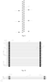
Fig. 11 illustrates a top view of a heat exchanger according to an example of the disclosure; -
Fig. 12 illustrates a left view of a heat exchanger according to an example of the disclosure; -
Fig. 13 illustrates a right view of a heat exchanger according to an example of the disclosure; -
Fig. 14 illustrates an exploded view of a partial structure of a heat exchanger according to an example of the disclosure; -
Fig. 15 illustrates a schematic structural diagram of a heat exchanger with two ends provided with fins according to an example of the disclosure; and -
Fig. 16 illustrates a schematic structural diagram of a heat exchanger according to an example of the disclosure. - The accompanying drawings include the following reference numerals:
10. heat exchange tube bank; 11. flat tube; 12. connection joint; 121. first connection joint; 122. second connection joint; 20. fin; 21. first snap-fit open slot; 22. second snap-fit open slot; 30. edge plate; 40. outlet manifold; 50. connection tube; and 60. inlet distribution head. - It is noted that examples in the disclosure and features in the examples can be combined with one another if there is no conflict. The disclosure will be described below in detail with reference to accompanying drawings and in conjunction with the examples.
- As shown in
Figs. 1-16 , some embodiments of the present disclosure provides a heat exchanger. The heat exchanger includes: a heatexchange tube bank 10, where the heatexchange tube bank 10 includes aflat tube 11 and aconnection joint 12, theflat tube 11 includes a first straight tube section, a bent tube section and a second straight tube section, and the first straight tube section, the bent tube section and the second straight tube section are sequentially connected to form a U-shaped tube structure. A plurality offlat tubes 11 are arranged, the plurality offlat tubes 11 are disposed at intervals, and two adjacentflat tubes 11 are in communication with each other through the connection joint 12. - By adopting such a structural arrangement, the connection joint 12 is disposed between two adjacent
flat tubes 11, the first connection port is connected with the first straight tube section of oneflat tube 11, and the second connection port is connected with the second straight tube section of anotherflat tube 11, such that the plurality offlat tubes 11 are in communication with one another conveniently. Merely one inlet tube and one outlet tube are disposed at twoflat tubes 11 at ends respectively, such that manufacturing and mounting of an inlet manifold and anoutlet manifold 40 are simplified. In view of that, by adopting the heat exchanger according to the disclosure, a technical problem that manufacturing and mounting of a manifold of a heat exchanger in the art known to inventors are complicated solved. - In some embodiments, the connection joint 12 has a first connection port and a second connection port that are in communication with each other. The first connection port is connected with the first straight tube section, and the second connection port is connected with the second straight tube section. The connection joint 12 is a U-shaped joint, and the first connection port and the second connection port are disposed at two ends of the U-shaped joint respectively. By adopting such a structural arrangement, the
flat tube 11 is arranged in a U-shaped tube structure, and the connection joint 12 is arranged in a U-shaped joint, such that the entire heatexchange tube bank 10 is in a bent structure, and a fluid can fully exchange heat. - In some embodiments, the plurality of
flat tubes 11 are uniformly distributed in rows to form a flat tube bank structure, the flat tube bank structure includes a plurality of flat tube rows disposed at intervals in a first preset direction, the flat tube row includes a plurality offlat tubes 11 disposed at intervals in a second preset direction, and the first preset direction and the second preset direction are set with a predetermined angle therebetween. The connection joint 12 is disposed between two adjacentflat tubes 11 in each flat tube row, and the connection joint 12 is disposed between two adjacent flat tube rows, such that theflat tubes 11 in the each flat tube row are in communication with one another and then in communication with an adjacent flat tube row. By adopting such a structural arrangement, theflat tubes 11 in each flat tube row are in communication with one another, and the plurality of flat tube rows are in communication with one another, such that a size of the flat tube bank structure in a length direction is reduced, structural layout of the flat tube bank structure is optimized, and compactness of the flat tube bank structure is improved. - In some embodiments, the connection joint 12 includes a first connection joint 121, the first connection joint 121 is disposed between the two adjacent
flat tubes 11 of the each flat tube row, and a first connection port of the first connection joint 121 and a second connection port of the first connection joint 121 are disposed at an interval in the second preset direction. By adopting such a structural arrangement, the two adjacentflat tubes 11 of the each flat tube row are better in communication with each other conveniently, and the plurality offlat tubes 11 in each flat tube row are in communication with one another. - In some embodiments, the connection joint 12 includes a second connection joint 122, the second connection joint 122 is disposed between the two adjacent flat tube rows, a first connection port of the second connection joint 122 and a second connection port of the second connection joint 122 are disposed at an interval in the first preset direction. By adopting such a structural arrangement, the two adjacent
flat tubes 11 of the each flat tube row are better in communication with each other conveniently, and the plurality of flat tube rows are in communication with one another. - In some embodiments, the
flat tube 11 rows are disposed in a staggered manner, and the first connection port of the second connection joint 122 and the second connection port of the second connection joint 122 are disposed at an interval in the second preset direction. By adopting such a structural arrangement, a staggered multi-row heat exchanger structure is formed, and structural layout of the heat exchanger and heat transfer performance are optimized. - In some embodiments, the heat exchanger further includes a
fin 20, where thefin 20 is provided with a plurality of snap-fit portions, the plurality of snap-fit portions and the plurality of flat tube rows are disposed in a one-to-one correspondingly manner, and each of plurality of the snap-fit portions is snapped on a corresponding flat tube row. By adopting such a structural arrangement, the snap-fit portions are arranged and snapped, and assembly and disassembly can be implemented conveniently. - In some embodiments, the flat tube bank structure includes two flat tube rows disposed at an interval, the plurality of snap-fit portions include a plurality of first snap-fit
open slots 21 disposed at intervals in the second preset direction and a plurality of second snap-fitopen slots 22 disposed at intervals in the second preset direction, the first snap-fitopen slot 21 and the second snap-fitopen slot 22 are disposed at two sides of thefin 20 respectively, and an opening direction of the first snap-fitopen slot 21 is opposite to an opening direction of the second snap-fitopen slot 22. By adopting such a structural arrangement, structural layout is optimized, the two flat tube rows are mounted conveniently, and a staggered double-row heat exchanger structure is formed conveniently. - In some embodiments, a distance between two adjacent flat tube rows is Wp, and 15≤Wp≤65.
- In some embodiments, a distance between two adjacent
flat tubes 11 in each flat tube row is Lp, and 6.5≤Lp≤35. - In some embodiments, the distance between two adjacent flat tube rows may be Wp, and 15≤Wp≤65. The distance between two adjacent
flat tubes 11 in each flat tube row is Lp, and 6.5≤Lp≤35. - In some embodiments, the distance between two adjacent flat tube rows in this example is Wp, and 15≤Wp≤65. When the WP distance is too small, and WP is less than 15, the distance between two adjacent flat tube rows is too small to facilitate effective heat exchange. When the Wp distance is too long, and Wp is greater than 65, the distance between two adjacent flat tube rows is too long, and a certain degree of heat loss is caused. In view of that, by setting Wp within the above range, effective heat exchange is facilitated and heat loss is reduced.
- In some embodiments, the distance between two adjacent
flat tubes 11 in each flat tube row is Lp, and 6.5≤Lp≤35. When the Lp distance is too small, and Lp is less than 6.5, the distance between two adjacentflat tube rows 11 is too small to facilitate effective heat exchange. When the Lp distance is too long, and Lp is greater than 35, the distance between two adjacentflat tubes 11 is too long, and great heat loss can be caused. In view of that, by setting Lp within the above range, effective heat exchange is facilitated and heat loss is reduced. - In some embodiments, a plurality of heat
exchange tube banks 10 are arranged, and the plurality of heatexchange tube banks 10 are disposed at intervals. Each of the plurality of heatexchange tube banks 10 is provided with an inlet tube and an outlet tube, and the heat exchanger further includes aninlet distribution head 60. The inlet tube is in communication with theinlet distribution head 60. By adopting such a structural arrangement, the plurality of heatexchange tube banks 10 form a plurality of independent heat exchange modules, such independent heat exchange is facilitated. The inlet tube is further provided with theinlet distribution head 60, such that distribution of the fluid is facilitated. Each of the inlet tube and the outlet tube is provided with aconnection tube 50, such that a connection is facilitated through theconnection tube 50. - In some embodiments, the heat exchanger further includes
fins 20 mounted on a plurality of heatexchange tube banks 10. Each of thefin 20 has a strip structure, and the plurality of heatexchange tube banks 10 are disposed at intervals in an extension direction of thefin 20. By adopting such a structural arrangement layout is optimized, and disassembly and assembly are facilitated. A plurality offins 20 are arranged, and the plurality offins 20 are sequentially inserted. - In some embodiments, each of the plurality of heat
exchange tube banks 10 includes two flat tube rows, the two flat tube rows are disposed at an interval in a direction perpendicular to thefin 20, and flat tube rows of each of the plurality of heatexchange tube bank 10 are oppositely arranged. By adopting such a structural arrangement, overall structural layout of the heat exchanger is optimized conveniently, and compactness and structural stability of layout of the heatexchange tube bank 10 is improved conveniently. - In some embodiments, the heat exchanger further includes an
outlet manifold 40, and the outlet tubes of the plurality of heatexchange tube banks 10 are all in communication with theoutlet manifold 40, such that collection of liquids at the plurality of outlet pipes is facilitated. - In some embodiments, the heat exchanger includes the
flat tubes 11 bent into a U shape, thefins 20 with recesses at two sides, and the connection joints 12 (the first connection joint 121 is configured to connectflat tubes 11 in the same row, and the second connection joint 122 is configured to connectflat tubes 11 across rows). Such the U-shapedflat tube 11 is formed through bending, a structure and a technology are simple, finished products have high precision, and assembly of thefins 20 on theflat tube 11 is guaranteed. Applicability to a staggered double-row insert heat exchanger is achieved, a simple structure with few parts is achieved, and desirable chip integrity and desirable reliability are achieved. - In some embodiments, the heat exchanger further includes an
edge plate 30, theedge plate 30 has a structure similar to a structure of thefin 20, and theedge plate 30 also has a structure with recesses at two sides. - From the above description, it can be seen that the above embodiments of the disclosure achieve the following technical effects of desirable integrity, desirable reliability, a simple structure and convenient disassembly and assembly.
- It should be noted that the terms used herein are merely for describing specific embodiments, and are not intended to limit illustrative embodiments according to the disclosure. As used herein, the singular form is also intended to include the plural form unless the context clearly indicates otherwise. Further, it should be understood that when the terms "comprise" and/or "include" are used in this description, the term specify presence of features, steps, operations, devices, assemblies and/or their combinations.
- Unless otherwise described specifically, relative arrangements, numeric expressions and values of components and steps set forth in these examples do not limit the scope of the disclosure. In addition, it should be understood that for the convenience of description, the dimensions of various parts shown in the accompanying drawings are not drawn according to the actual proportional relation. Technologies, methods and apparatuses known to those of ordinary skill in related fields may not be discussed in detail, but in appropriate cases, the technologies, methods and apparatuses should be regarded as a constituent part of the authorized description. In all examples shown and discussed herein, any specific value should be constructed as merely illustrative rather than limitative. As a result, other instances of illustrative examples can have different values. It should be noted that similar reference numerals and letters indicate similar items in the following accompanying drawings, and once defined in one accompanying drawing, an item is unnecessary to further define and explain in subsequent accompanying drawings.
- In the description of the disclosure, it needs to be understood the orientation or positional relations indicated by the orientation terms such as "front", "rear", "up", "down", "left", "right", "transverse", "vertical", "perpendicular", "horizontal", "top", and "bottom" are based on the orientation or positional relations shown in the accompanying drawings, are merely for facilitating the description of the disclosure and simplifying the description, rather than indicating or implying that an apparatus or element referred to must have a particular orientation or be constructed and operated in a particular orientation in the absence of contrary description, and cannot be interpreted as limitation to the disclosure accordingly. The orientation terms "inside" and "outside" refer to inside and outside relative to an outline of each component itself.
- For the convenience of description, spatially relative terms such as "over", "above", "on an upper surface of" and "on" can be used herein to describe a spatial positional relation between a device or feature as shown in the figure and other devices or features. It should be understood that the spatially relative terms are intended to include different orientations in use or operation in addition to the orientation of the device depicted in the figure. For example, if the device in the figure is inverted, the device that is described as "above another device or structure" or "over another device or structure" will be positioned as "below another device or structure" or "under another device or structure". As a result, the illustrative term "above" can include two orientations of "above" and "below". The device can also be positioned in other different ways (rotated by 90 degrees or in other orientations), and spatial relative description used herein is explained accordingly.
- In addition, it should be noted that the terms such as "first" and "second" are used for defining parts, and are merely used for conveniently distinguishing corresponding parts. The terms have no special meanings unless otherwise stated, and shall not be understood as limitation to the protection scope of the disclosure.
- The above examples are merely preferred examples of the disclosure and are not intended to limit the disclosure, and for those skilled in the art, various modifications and changes can be made to the disclosure. Any modification, equivalent substitution, improvement, etc. made within the spirit and principles of the disclosure shall fall within the protection scope of the disclosure.
Claims (11)
- A heat exchanger, comprising:
a heat exchange tube bank (10), wherein the heat exchange tube bank (10) comprises a flat tube (11) and a connection joint (12); the flat tube (11) comprises a first straight tube section, a bent tube section and a second straight tube section, and the first straight tube section, the bent tube section and the second straight tube section are sequentially connected to form a U-shaped tube structure; and a plurality of flat tubes (11) are arranged, the plurality of flat tubes (11) are disposed at intervals, and two adjacent flat tubes (11) are in communication with each other through the connection joint (12). - The heat exchanger as claimed in claim 1, wherein the connection joint (12) has a first connection port and a second connection port that are in communication with each other; the first connection port is connected with the first straight tube section, and the second connection port is connected with the second straight tube section; and the connection joint (12) is a U-shaped joint, and the first connection port and the second connection port are disposed at two ends of the U-shaped joint respectively.
- The heat exchanger as claimed in claim 1, wherein the plurality of flat tubes (11) are uniformly distributed in rows to form a flat tube bank structure, the flat tube bank structure comprises a plurality of flat tube rows disposed at intervals in a first preset direction, the flat tube row comprises a plurality of flat tubes (11) disposed at intervals in a second preset direction, and the first preset direction and the second preset direction are set with a predetermined angle therebetween; and
the connection joint (12) is disposed between two adjacent flat tubes (11) in each flat tube row, and the connection joint (12) is disposed between two adjacent flat tube rows, such that the flat tubes (11) in the each flat tube row are in communication with one another and then in communication with an adjacent flat tube row. - The heat exchanger as claimed in claim 3, wherein the connection joints (12) comprise:
a first connection joint (121) disposed between the two adjacent flat tubes (11) of the each flat tube row, wherein a first connection port of the first connection joint (121) and a second connection port of the first connection joint (121) are disposed at an interval in the second preset direction. - The heat exchanger as claimed in claim 3, wherein the connection joints (12) comprise:
a second connection joint (122) disposed between the two adjacent flat tube rows, wherein a first connection port of the second connection joint (122) and a second connection port of the second connection joint (122) are disposed at an interval in the first preset direction. - The heat exchanger as claimed in claim 5, wherein the flat tube (11) rows are disposed in a staggered manner, and the first connection port of the second connection joint (122) and the second connection port of the second connection joint (122) are disposed at an interval in the second preset direction.
- The heat exchanger as claimed in claim 3, further comprising:
a fin (20), wherein the fin (20) is provided with a plurality of snap-fit portions, the plurality of snap-fit portions and the plurality of flat tube rows are disposed in a one-to-one correspondingly manner, and each of the plurality of snap-fit portions is snapped on a corresponding flat tube row. - The heat exchanger as claimed in claim 7, wherein the flat tube bank structure comprises two flat tube rows disposed at an interval, the plurality of snap-fit portions comprise a plurality of first snap-fit open slots (21) disposed at intervals in the second preset direction and a plurality of second snap-fit open slots (22) disposed at intervals in the second preset direction, the first snap-fit open slot (21) and the second snap-fit open slot (22) are disposed at two sides of the fin (20) respectively, and an opening direction of the first snap-fit open slot (21) is opposite to an opening direction of the second snap-fit open slot (22).
- The heat exchanger as claimed in any one of claims 3-8, whereina distance between two adjacent flat tube rows is Wp, and 15≤Wp≤65; and/or,a distance between two adjacent flat tubes (11) in each flat tube row is Lp, and 6.5≤Lp≤35.
- The heat exchanger as claimed in claim 1, wherein a plurality of heat exchange tube banks (10) are arranged, and the plurality of heat exchange tube banks (10) are disposed at intervals; each of the plurality of heat exchange tube banks (10) has an inlet tube and an outlet tube, and the heat exchanger further comprises an inlet distribution head (60); and the inlet tube is in communication with the inlet distribution head (60).
- The heat exchanger as claimed in claim 10, further comprising an outlet manifold (40), wherein the outlet tube is in communication with the outlet manifold (40).
Applications Claiming Priority (2)
| Application Number | Priority Date | Filing Date | Title |
|---|---|---|---|
| CN202121202521.7U CN215114092U (en) | 2021-05-31 | 2021-05-31 | Heat exchanger |
| PCT/CN2022/096133 WO2022253206A1 (en) | 2021-05-31 | 2022-05-31 | Heat exchanger |
Publications (2)
| Publication Number | Publication Date |
|---|---|
| EP4354068A1 true EP4354068A1 (en) | 2024-04-17 |
| EP4354068A4 EP4354068A4 (en) | 2024-09-18 |
Family
ID=79301984
Family Applications (1)
| Application Number | Title | Priority Date | Filing Date |
|---|---|---|---|
| EP22815251.8A Pending EP4354068A4 (en) | 2021-05-31 | 2022-05-31 | HEAT EXCHANGER |
Country Status (6)
| Country | Link |
|---|---|
| US (1) | US20240255232A1 (en) |
| EP (1) | EP4354068A4 (en) |
| JP (1) | JP7675207B2 (en) |
| KR (1) | KR20240013803A (en) |
| CN (1) | CN215114092U (en) |
| WO (1) | WO2022253206A1 (en) |
Families Citing this family (3)
| Publication number | Priority date | Publication date | Assignee | Title |
|---|---|---|---|---|
| CN215114092U (en) * | 2021-05-31 | 2021-12-10 | 浙江盾安热工科技有限公司 | Heat exchanger |
| CN215984104U (en) * | 2021-06-17 | 2022-03-08 | 浙江盾安热工科技有限公司 | Heat exchanger |
| CN217464958U (en) * | 2022-04-29 | 2022-09-20 | 浙江盾安热工科技有限公司 | Microchannel heat exchanger group and air conditioning system having the same |
Family Cites Families (14)
| Publication number | Priority date | Publication date | Assignee | Title |
|---|---|---|---|---|
| EP0138435A3 (en) * | 1983-10-19 | 1986-05-14 | General Motors Corporation | Tube and fin heat exchanger |
| JPH1089870A (en) * | 1996-09-18 | 1998-04-10 | Nippon Light Metal Co Ltd | Heat exchanger manufacturing method and heat exchanger |
| JP2008261615A (en) * | 2007-03-16 | 2008-10-30 | Mitsubishi Electric Corp | Heat exchanger, heat exchanger, refrigerator, air conditioner |
| JP2009216315A (en) * | 2008-03-11 | 2009-09-24 | Showa Denko Kk | Heat exchanger |
| JP5195733B2 (en) * | 2009-12-17 | 2013-05-15 | 三菱電機株式会社 | Heat exchanger and refrigeration cycle apparatus equipped with the same |
| US20110247794A1 (en) * | 2010-04-12 | 2011-10-13 | Bradley Arment | Flattened tubes for use in heat exchangers and other systems, and associated methods of manufacture and use |
| CN201964816U (en) * | 2011-02-15 | 2011-09-07 | 金龙精密铜管集团股份有限公司 | Specially-shaped mouth micro-channel heat exchange flat tube and heat exchanger |
| EP2851641B1 (en) * | 2012-04-26 | 2019-09-11 | Mitsubishi Electric Corporation | Heat exchanger, indoor unit, and refrigeration cycle device |
| US10907902B2 (en) * | 2015-09-10 | 2021-02-02 | Hitachi-Johnson Controls Air Conditioning, Inc. | Heat exchanger |
| GB2561098B (en) * | 2015-12-25 | 2021-08-04 | Mitsubishi Electric Corp | Heat exchanger, air-conditioning apparatus including the same, and method of producing flat-tube u-bend |
| CN106524594A (en) * | 2016-10-13 | 2017-03-22 | 杭州三花家电热管理系统有限公司 | Coil pipe type heat exchanger |
| CN206514572U (en) * | 2016-12-30 | 2017-09-22 | 杭州三花家电热管理系统有限公司 | Micro-channel heat exchanger and the refrigerating plant with it |
| CN211601198U (en) * | 2019-12-31 | 2020-09-29 | 浙江盾安热工科技有限公司 | Heat exchanger |
| CN215114092U (en) * | 2021-05-31 | 2021-12-10 | 浙江盾安热工科技有限公司 | Heat exchanger |
-
2021
- 2021-05-31 CN CN202121202521.7U patent/CN215114092U/en active Active
-
2022
- 2022-05-31 US US18/565,543 patent/US20240255232A1/en active Pending
- 2022-05-31 EP EP22815251.8A patent/EP4354068A4/en active Pending
- 2022-05-31 JP JP2023563199A patent/JP7675207B2/en active Active
- 2022-05-31 WO PCT/CN2022/096133 patent/WO2022253206A1/en not_active Ceased
- 2022-05-31 KR KR1020237044917A patent/KR20240013803A/en active Pending
Also Published As
| Publication number | Publication date |
|---|---|
| US20240255232A1 (en) | 2024-08-01 |
| JP7675207B2 (en) | 2025-05-12 |
| WO2022253206A1 (en) | 2022-12-08 |
| CN215114092U (en) | 2021-12-10 |
| JP2024519278A (en) | 2024-05-10 |
| EP4354068A4 (en) | 2024-09-18 |
| KR20240013803A (en) | 2024-01-30 |
Similar Documents
| Publication | Publication Date | Title |
|---|---|---|
| EP4354068A1 (en) | Heat exchanger | |
| US10048020B2 (en) | Heat transfer surfaces with flanged apertures | |
| CN101517347B (en) | Heat exchanger and manufacturing method thereof | |
| US10113817B2 (en) | Heater core | |
| US20100230081A1 (en) | Corrugated Micro Tube Heat Exchanger | |
| CN110686429B (en) | Microchannel Heat Exchanger | |
| EP4354072A1 (en) | Connecting joint tube and heat exchanger having same | |
| CN105277040B (en) | Heat exchanger | |
| US20130248158A1 (en) | Method for manufacturing refrigerant guide tube of heat exchanger, refrigerant guide tube manufactured using the method and heat exchanger with the refrigerant guide tube | |
| EP4425082B1 (en) | Micro-channel heat exchanger | |
| CN216205612U (en) | Distribution structure and plate heat exchanger with same | |
| US7073574B2 (en) | Method and apparatus for forming fins for a heat exchanger | |
| CN212390892U (en) | Fin, heat exchanger and air conditioner | |
| CN220507812U (en) | Microchannel single-row zigzag fin, fin assembly and heat exchanger | |
| CN208012442U (en) | Fins, microchannel heat exchangers and air conditioners | |
| WO2021057984A1 (en) | Heat exchanger | |
| WO2023185343A1 (en) | Heat exchanger | |
| JP2023525660A (en) | Flat heat exchange tube and heat exchanger having the same | |
| CN113834369A (en) | Distribution structure and plate heat exchanger having the same | |
| CN105486150A (en) | Heat exchange part and heat exchanger | |
| CN106595130A (en) | Plate header pipe and heat exchanger | |
| EP2064509A1 (en) | Heat transfer surfaces with flanged apertures | |
| CN205482514U (en) | Heat transfer piece and heat exchanger | |
| CN216620358U (en) | Heat exchanger and air conditioner with same | |
| CN221959319U (en) | Heat Exchanger |
Legal Events
| Date | Code | Title | Description |
|---|---|---|---|
| STAA | Information on the status of an ep patent application or granted ep patent |
Free format text: STATUS: THE INTERNATIONAL PUBLICATION HAS BEEN MADE |
|
| PUAI | Public reference made under article 153(3) epc to a published international application that has entered the european phase |
Free format text: ORIGINAL CODE: 0009012 |
|
| STAA | Information on the status of an ep patent application or granted ep patent |
Free format text: STATUS: REQUEST FOR EXAMINATION WAS MADE |
|
| 17P | Request for examination filed |
Effective date: 20231219 |
|
| AK | Designated contracting states |
Kind code of ref document: A1 Designated state(s): AL AT BE BG CH CY CZ DE DK EE ES FI FR GB GR HR HU IE IS IT LI LT LU LV MC MK MT NL NO PL PT RO RS SE SI SK SM TR |
|
| DAV | Request for validation of the european patent (deleted) | ||
| DAX | Request for extension of the european patent (deleted) | ||
| A4 | Supplementary search report drawn up and despatched |
Effective date: 20240819 |
|
| RIC1 | Information provided on ipc code assigned before grant |
Ipc: F28F 1/32 20060101ALI20240812BHEP Ipc: F28F 9/26 20060101ALI20240812BHEP Ipc: F28D 1/053 20060101AFI20240812BHEP |