EP4354011A1 - Pressure accumulator - Google Patents
Pressure accumulator Download PDFInfo
- Publication number
- EP4354011A1 EP4354011A1 EP22820293.3A EP22820293A EP4354011A1 EP 4354011 A1 EP4354011 A1 EP 4354011A1 EP 22820293 A EP22820293 A EP 22820293A EP 4354011 A1 EP4354011 A1 EP 4354011A1
- Authority
- EP
- European Patent Office
- Prior art keywords
- lid body
- cylindrical body
- pressure accumulator
- gap
- pipe
- Prior art date
- Legal status (The legal status is an assumption and is not a legal conclusion. Google has not performed a legal analysis and makes no representation as to the accuracy of the status listed.)
- Pending
Links
Images


Classifications
-
- F—MECHANICAL ENGINEERING; LIGHTING; HEATING; WEAPONS; BLASTING
- F17—STORING OR DISTRIBUTING GASES OR LIQUIDS
- F17C—VESSELS FOR CONTAINING OR STORING COMPRESSED, LIQUEFIED OR SOLIDIFIED GASES; FIXED-CAPACITY GAS-HOLDERS; FILLING VESSELS WITH, OR DISCHARGING FROM VESSELS, COMPRESSED, LIQUEFIED, OR SOLIDIFIED GASES
- F17C13/00—Details of vessels or of the filling or discharging of vessels
- F17C13/06—Closures, e.g. cap, breakable member
-
- F—MECHANICAL ENGINEERING; LIGHTING; HEATING; WEAPONS; BLASTING
- F17—STORING OR DISTRIBUTING GASES OR LIQUIDS
- F17C—VESSELS FOR CONTAINING OR STORING COMPRESSED, LIQUEFIED OR SOLIDIFIED GASES; FIXED-CAPACITY GAS-HOLDERS; FILLING VESSELS WITH, OR DISCHARGING FROM VESSELS, COMPRESSED, LIQUEFIED, OR SOLIDIFIED GASES
- F17C1/00—Pressure vessels, e.g. gas cylinder, gas tank, replaceable cartridge
- F17C1/02—Pressure vessels, e.g. gas cylinder, gas tank, replaceable cartridge involving reinforcing arrangements
- F17C1/04—Protecting sheathings
-
- F—MECHANICAL ENGINEERING; LIGHTING; HEATING; WEAPONS; BLASTING
- F17—STORING OR DISTRIBUTING GASES OR LIQUIDS
- F17C—VESSELS FOR CONTAINING OR STORING COMPRESSED, LIQUEFIED OR SOLIDIFIED GASES; FIXED-CAPACITY GAS-HOLDERS; FILLING VESSELS WITH, OR DISCHARGING FROM VESSELS, COMPRESSED, LIQUEFIED, OR SOLIDIFIED GASES
- F17C1/00—Pressure vessels, e.g. gas cylinder, gas tank, replaceable cartridge
- F17C1/02—Pressure vessels, e.g. gas cylinder, gas tank, replaceable cartridge involving reinforcing arrangements
- F17C1/04—Protecting sheathings
- F17C1/06—Protecting sheathings built-up from wound-on bands or filamentary material, e.g. wires
-
- F—MECHANICAL ENGINEERING; LIGHTING; HEATING; WEAPONS; BLASTING
- F15—FLUID-PRESSURE ACTUATORS; HYDRAULICS OR PNEUMATICS IN GENERAL
- F15B—SYSTEMS ACTING BY MEANS OF FLUIDS IN GENERAL; FLUID-PRESSURE ACTUATORS, e.g. SERVOMOTORS; DETAILS OF FLUID-PRESSURE SYSTEMS, NOT OTHERWISE PROVIDED FOR
- F15B1/00—Installations or systems with accumulators; Supply reservoir or sump assemblies
- F15B1/02—Installations or systems with accumulators
- F15B1/04—Accumulators
-
- F—MECHANICAL ENGINEERING; LIGHTING; HEATING; WEAPONS; BLASTING
- F17—STORING OR DISTRIBUTING GASES OR LIQUIDS
- F17C—VESSELS FOR CONTAINING OR STORING COMPRESSED, LIQUEFIED OR SOLIDIFIED GASES; FIXED-CAPACITY GAS-HOLDERS; FILLING VESSELS WITH, OR DISCHARGING FROM VESSELS, COMPRESSED, LIQUEFIED, OR SOLIDIFIED GASES
- F17C13/00—Details of vessels or of the filling or discharging of vessels
- F17C13/002—Details of vessels or of the filling or discharging of vessels for vessels under pressure
-
- F—MECHANICAL ENGINEERING; LIGHTING; HEATING; WEAPONS; BLASTING
- F17—STORING OR DISTRIBUTING GASES OR LIQUIDS
- F17C—VESSELS FOR CONTAINING OR STORING COMPRESSED, LIQUEFIED OR SOLIDIFIED GASES; FIXED-CAPACITY GAS-HOLDERS; FILLING VESSELS WITH, OR DISCHARGING FROM VESSELS, COMPRESSED, LIQUEFIED, OR SOLIDIFIED GASES
- F17C13/00—Details of vessels or of the filling or discharging of vessels
- F17C13/02—Special adaptations of indicating, measuring, or monitoring equipment
- F17C13/026—Special adaptations of indicating, measuring, or monitoring equipment having the temperature as the parameter
-
- F—MECHANICAL ENGINEERING; LIGHTING; HEATING; WEAPONS; BLASTING
- F17—STORING OR DISTRIBUTING GASES OR LIQUIDS
- F17C—VESSELS FOR CONTAINING OR STORING COMPRESSED, LIQUEFIED OR SOLIDIFIED GASES; FIXED-CAPACITY GAS-HOLDERS; FILLING VESSELS WITH, OR DISCHARGING FROM VESSELS, COMPRESSED, LIQUEFIED, OR SOLIDIFIED GASES
- F17C5/00—Methods or apparatus for filling containers with liquefied, solidified, or compressed gases under pressures
- F17C5/06—Methods or apparatus for filling containers with liquefied, solidified, or compressed gases under pressures for filling with compressed gases
-
- F—MECHANICAL ENGINEERING; LIGHTING; HEATING; WEAPONS; BLASTING
- F17—STORING OR DISTRIBUTING GASES OR LIQUIDS
- F17C—VESSELS FOR CONTAINING OR STORING COMPRESSED, LIQUEFIED OR SOLIDIFIED GASES; FIXED-CAPACITY GAS-HOLDERS; FILLING VESSELS WITH, OR DISCHARGING FROM VESSELS, COMPRESSED, LIQUEFIED, OR SOLIDIFIED GASES
- F17C2201/00—Vessel construction, in particular geometry, arrangement or size
- F17C2201/01—Shape
- F17C2201/0104—Shape cylindrical
- F17C2201/0119—Shape cylindrical with flat end-piece
-
- F—MECHANICAL ENGINEERING; LIGHTING; HEATING; WEAPONS; BLASTING
- F17—STORING OR DISTRIBUTING GASES OR LIQUIDS
- F17C—VESSELS FOR CONTAINING OR STORING COMPRESSED, LIQUEFIED OR SOLIDIFIED GASES; FIXED-CAPACITY GAS-HOLDERS; FILLING VESSELS WITH, OR DISCHARGING FROM VESSELS, COMPRESSED, LIQUEFIED, OR SOLIDIFIED GASES
- F17C2201/00—Vessel construction, in particular geometry, arrangement or size
- F17C2201/01—Shape
- F17C2201/0138—Shape tubular
-
- F—MECHANICAL ENGINEERING; LIGHTING; HEATING; WEAPONS; BLASTING
- F17—STORING OR DISTRIBUTING GASES OR LIQUIDS
- F17C—VESSELS FOR CONTAINING OR STORING COMPRESSED, LIQUEFIED OR SOLIDIFIED GASES; FIXED-CAPACITY GAS-HOLDERS; FILLING VESSELS WITH, OR DISCHARGING FROM VESSELS, COMPRESSED, LIQUEFIED, OR SOLIDIFIED GASES
- F17C2201/00—Vessel construction, in particular geometry, arrangement or size
- F17C2201/01—Shape
- F17C2201/0147—Shape complex
- F17C2201/0157—Polygonal
-
- F—MECHANICAL ENGINEERING; LIGHTING; HEATING; WEAPONS; BLASTING
- F17—STORING OR DISTRIBUTING GASES OR LIQUIDS
- F17C—VESSELS FOR CONTAINING OR STORING COMPRESSED, LIQUEFIED OR SOLIDIFIED GASES; FIXED-CAPACITY GAS-HOLDERS; FILLING VESSELS WITH, OR DISCHARGING FROM VESSELS, COMPRESSED, LIQUEFIED, OR SOLIDIFIED GASES
- F17C2201/00—Vessel construction, in particular geometry, arrangement or size
- F17C2201/05—Size
- F17C2201/056—Small (<1 m3)
-
- F—MECHANICAL ENGINEERING; LIGHTING; HEATING; WEAPONS; BLASTING
- F17—STORING OR DISTRIBUTING GASES OR LIQUIDS
- F17C—VESSELS FOR CONTAINING OR STORING COMPRESSED, LIQUEFIED OR SOLIDIFIED GASES; FIXED-CAPACITY GAS-HOLDERS; FILLING VESSELS WITH, OR DISCHARGING FROM VESSELS, COMPRESSED, LIQUEFIED, OR SOLIDIFIED GASES
- F17C2203/00—Vessel construction, in particular walls or details thereof
- F17C2203/06—Materials for walls or layers thereof; Properties or structures of walls or their materials
- F17C2203/0602—Wall structures; Special features thereof
- F17C2203/0612—Wall structures
- F17C2203/0614—Single wall
- F17C2203/0617—Single wall with one layer
-
- F—MECHANICAL ENGINEERING; LIGHTING; HEATING; WEAPONS; BLASTING
- F17—STORING OR DISTRIBUTING GASES OR LIQUIDS
- F17C—VESSELS FOR CONTAINING OR STORING COMPRESSED, LIQUEFIED OR SOLIDIFIED GASES; FIXED-CAPACITY GAS-HOLDERS; FILLING VESSELS WITH, OR DISCHARGING FROM VESSELS, COMPRESSED, LIQUEFIED, OR SOLIDIFIED GASES
- F17C2203/00—Vessel construction, in particular walls or details thereof
- F17C2203/06—Materials for walls or layers thereof; Properties or structures of walls or their materials
- F17C2203/0602—Wall structures; Special features thereof
- F17C2203/0612—Wall structures
- F17C2203/0614—Single wall
- F17C2203/0619—Single wall with two layers
-
- F—MECHANICAL ENGINEERING; LIGHTING; HEATING; WEAPONS; BLASTING
- F17—STORING OR DISTRIBUTING GASES OR LIQUIDS
- F17C—VESSELS FOR CONTAINING OR STORING COMPRESSED, LIQUEFIED OR SOLIDIFIED GASES; FIXED-CAPACITY GAS-HOLDERS; FILLING VESSELS WITH, OR DISCHARGING FROM VESSELS, COMPRESSED, LIQUEFIED, OR SOLIDIFIED GASES
- F17C2203/00—Vessel construction, in particular walls or details thereof
- F17C2203/06—Materials for walls or layers thereof; Properties or structures of walls or their materials
- F17C2203/0634—Materials for walls or layers thereof
- F17C2203/0636—Metals
- F17C2203/0639—Steels
-
- F—MECHANICAL ENGINEERING; LIGHTING; HEATING; WEAPONS; BLASTING
- F17—STORING OR DISTRIBUTING GASES OR LIQUIDS
- F17C—VESSELS FOR CONTAINING OR STORING COMPRESSED, LIQUEFIED OR SOLIDIFIED GASES; FIXED-CAPACITY GAS-HOLDERS; FILLING VESSELS WITH, OR DISCHARGING FROM VESSELS, COMPRESSED, LIQUEFIED, OR SOLIDIFIED GASES
- F17C2203/00—Vessel construction, in particular walls or details thereof
- F17C2203/06—Materials for walls or layers thereof; Properties or structures of walls or their materials
- F17C2203/0634—Materials for walls or layers thereof
- F17C2203/0636—Metals
- F17C2203/0639—Steels
- F17C2203/0643—Stainless steels
-
- F—MECHANICAL ENGINEERING; LIGHTING; HEATING; WEAPONS; BLASTING
- F17—STORING OR DISTRIBUTING GASES OR LIQUIDS
- F17C—VESSELS FOR CONTAINING OR STORING COMPRESSED, LIQUEFIED OR SOLIDIFIED GASES; FIXED-CAPACITY GAS-HOLDERS; FILLING VESSELS WITH, OR DISCHARGING FROM VESSELS, COMPRESSED, LIQUEFIED, OR SOLIDIFIED GASES
- F17C2203/00—Vessel construction, in particular walls or details thereof
- F17C2203/06—Materials for walls or layers thereof; Properties or structures of walls or their materials
- F17C2203/0634—Materials for walls or layers thereof
- F17C2203/0636—Metals
- F17C2203/0648—Alloys or compositions of metals
-
- F—MECHANICAL ENGINEERING; LIGHTING; HEATING; WEAPONS; BLASTING
- F17—STORING OR DISTRIBUTING GASES OR LIQUIDS
- F17C—VESSELS FOR CONTAINING OR STORING COMPRESSED, LIQUEFIED OR SOLIDIFIED GASES; FIXED-CAPACITY GAS-HOLDERS; FILLING VESSELS WITH, OR DISCHARGING FROM VESSELS, COMPRESSED, LIQUEFIED, OR SOLIDIFIED GASES
- F17C2203/00—Vessel construction, in particular walls or details thereof
- F17C2203/06—Materials for walls or layers thereof; Properties or structures of walls or their materials
- F17C2203/0634—Materials for walls or layers thereof
- F17C2203/0658—Synthetics
- F17C2203/0663—Synthetics in form of fibers or filaments
-
- F—MECHANICAL ENGINEERING; LIGHTING; HEATING; WEAPONS; BLASTING
- F17—STORING OR DISTRIBUTING GASES OR LIQUIDS
- F17C—VESSELS FOR CONTAINING OR STORING COMPRESSED, LIQUEFIED OR SOLIDIFIED GASES; FIXED-CAPACITY GAS-HOLDERS; FILLING VESSELS WITH, OR DISCHARGING FROM VESSELS, COMPRESSED, LIQUEFIED, OR SOLIDIFIED GASES
- F17C2205/00—Vessel construction, in particular mounting arrangements, attachments or identifications means
- F17C2205/03—Fluid connections, filters, valves, closure means or other attachments
- F17C2205/0302—Fittings, valves, filters, or components in connection with the gas storage device
- F17C2205/0305—Bosses, e.g. boss collars
-
- F—MECHANICAL ENGINEERING; LIGHTING; HEATING; WEAPONS; BLASTING
- F17—STORING OR DISTRIBUTING GASES OR LIQUIDS
- F17C—VESSELS FOR CONTAINING OR STORING COMPRESSED, LIQUEFIED OR SOLIDIFIED GASES; FIXED-CAPACITY GAS-HOLDERS; FILLING VESSELS WITH, OR DISCHARGING FROM VESSELS, COMPRESSED, LIQUEFIED, OR SOLIDIFIED GASES
- F17C2205/00—Vessel construction, in particular mounting arrangements, attachments or identifications means
- F17C2205/03—Fluid connections, filters, valves, closure means or other attachments
- F17C2205/0302—Fittings, valves, filters, or components in connection with the gas storage device
- F17C2205/0311—Closure means
-
- F—MECHANICAL ENGINEERING; LIGHTING; HEATING; WEAPONS; BLASTING
- F17—STORING OR DISTRIBUTING GASES OR LIQUIDS
- F17C—VESSELS FOR CONTAINING OR STORING COMPRESSED, LIQUEFIED OR SOLIDIFIED GASES; FIXED-CAPACITY GAS-HOLDERS; FILLING VESSELS WITH, OR DISCHARGING FROM VESSELS, COMPRESSED, LIQUEFIED, OR SOLIDIFIED GASES
- F17C2205/00—Vessel construction, in particular mounting arrangements, attachments or identifications means
- F17C2205/03—Fluid connections, filters, valves, closure means or other attachments
- F17C2205/0302—Fittings, valves, filters, or components in connection with the gas storage device
- F17C2205/0352—Pipes
- F17C2205/0355—Insulation thereof
-
- F—MECHANICAL ENGINEERING; LIGHTING; HEATING; WEAPONS; BLASTING
- F17—STORING OR DISTRIBUTING GASES OR LIQUIDS
- F17C—VESSELS FOR CONTAINING OR STORING COMPRESSED, LIQUEFIED OR SOLIDIFIED GASES; FIXED-CAPACITY GAS-HOLDERS; FILLING VESSELS WITH, OR DISCHARGING FROM VESSELS, COMPRESSED, LIQUEFIED, OR SOLIDIFIED GASES
- F17C2209/00—Vessel construction, in particular methods of manufacturing
- F17C2209/22—Assembling processes
- F17C2209/221—Welding
-
- F—MECHANICAL ENGINEERING; LIGHTING; HEATING; WEAPONS; BLASTING
- F17—STORING OR DISTRIBUTING GASES OR LIQUIDS
- F17C—VESSELS FOR CONTAINING OR STORING COMPRESSED, LIQUEFIED OR SOLIDIFIED GASES; FIXED-CAPACITY GAS-HOLDERS; FILLING VESSELS WITH, OR DISCHARGING FROM VESSELS, COMPRESSED, LIQUEFIED, OR SOLIDIFIED GASES
- F17C2209/00—Vessel construction, in particular methods of manufacturing
- F17C2209/22—Assembling processes
- F17C2209/228—Assembling processes by screws, bolts or rivets
-
- F—MECHANICAL ENGINEERING; LIGHTING; HEATING; WEAPONS; BLASTING
- F17—STORING OR DISTRIBUTING GASES OR LIQUIDS
- F17C—VESSELS FOR CONTAINING OR STORING COMPRESSED, LIQUEFIED OR SOLIDIFIED GASES; FIXED-CAPACITY GAS-HOLDERS; FILLING VESSELS WITH, OR DISCHARGING FROM VESSELS, COMPRESSED, LIQUEFIED, OR SOLIDIFIED GASES
- F17C2209/00—Vessel construction, in particular methods of manufacturing
- F17C2209/23—Manufacturing of particular parts or at special locations
- F17C2209/232—Manufacturing of particular parts or at special locations of walls
-
- F—MECHANICAL ENGINEERING; LIGHTING; HEATING; WEAPONS; BLASTING
- F17—STORING OR DISTRIBUTING GASES OR LIQUIDS
- F17C—VESSELS FOR CONTAINING OR STORING COMPRESSED, LIQUEFIED OR SOLIDIFIED GASES; FIXED-CAPACITY GAS-HOLDERS; FILLING VESSELS WITH, OR DISCHARGING FROM VESSELS, COMPRESSED, LIQUEFIED, OR SOLIDIFIED GASES
- F17C2209/00—Vessel construction, in particular methods of manufacturing
- F17C2209/23—Manufacturing of particular parts or at special locations
- F17C2209/234—Manufacturing of particular parts or at special locations of closing end pieces, e.g. caps
-
- F—MECHANICAL ENGINEERING; LIGHTING; HEATING; WEAPONS; BLASTING
- F17—STORING OR DISTRIBUTING GASES OR LIQUIDS
- F17C—VESSELS FOR CONTAINING OR STORING COMPRESSED, LIQUEFIED OR SOLIDIFIED GASES; FIXED-CAPACITY GAS-HOLDERS; FILLING VESSELS WITH, OR DISCHARGING FROM VESSELS, COMPRESSED, LIQUEFIED, OR SOLIDIFIED GASES
- F17C2221/00—Handled fluid, in particular type of fluid
- F17C2221/01—Pure fluids
- F17C2221/012—Hydrogen
-
- F—MECHANICAL ENGINEERING; LIGHTING; HEATING; WEAPONS; BLASTING
- F17—STORING OR DISTRIBUTING GASES OR LIQUIDS
- F17C—VESSELS FOR CONTAINING OR STORING COMPRESSED, LIQUEFIED OR SOLIDIFIED GASES; FIXED-CAPACITY GAS-HOLDERS; FILLING VESSELS WITH, OR DISCHARGING FROM VESSELS, COMPRESSED, LIQUEFIED, OR SOLIDIFIED GASES
- F17C2221/00—Handled fluid, in particular type of fluid
- F17C2221/01—Pure fluids
- F17C2221/014—Nitrogen
-
- F—MECHANICAL ENGINEERING; LIGHTING; HEATING; WEAPONS; BLASTING
- F17—STORING OR DISTRIBUTING GASES OR LIQUIDS
- F17C—VESSELS FOR CONTAINING OR STORING COMPRESSED, LIQUEFIED OR SOLIDIFIED GASES; FIXED-CAPACITY GAS-HOLDERS; FILLING VESSELS WITH, OR DISCHARGING FROM VESSELS, COMPRESSED, LIQUEFIED, OR SOLIDIFIED GASES
- F17C2221/00—Handled fluid, in particular type of fluid
- F17C2221/01—Pure fluids
- F17C2221/016—Noble gases (Ar, Kr, Xe)
- F17C2221/017—Helium
-
- F—MECHANICAL ENGINEERING; LIGHTING; HEATING; WEAPONS; BLASTING
- F17—STORING OR DISTRIBUTING GASES OR LIQUIDS
- F17C—VESSELS FOR CONTAINING OR STORING COMPRESSED, LIQUEFIED OR SOLIDIFIED GASES; FIXED-CAPACITY GAS-HOLDERS; FILLING VESSELS WITH, OR DISCHARGING FROM VESSELS, COMPRESSED, LIQUEFIED, OR SOLIDIFIED GASES
- F17C2223/00—Handled fluid before transfer, i.e. state of fluid when stored in the vessel or before transfer from the vessel
- F17C2223/01—Handled fluid before transfer, i.e. state of fluid when stored in the vessel or before transfer from the vessel characterised by the phase
- F17C2223/0107—Single phase
- F17C2223/0123—Single phase gaseous, e.g. CNG, GNC
-
- F—MECHANICAL ENGINEERING; LIGHTING; HEATING; WEAPONS; BLASTING
- F17—STORING OR DISTRIBUTING GASES OR LIQUIDS
- F17C—VESSELS FOR CONTAINING OR STORING COMPRESSED, LIQUEFIED OR SOLIDIFIED GASES; FIXED-CAPACITY GAS-HOLDERS; FILLING VESSELS WITH, OR DISCHARGING FROM VESSELS, COMPRESSED, LIQUEFIED, OR SOLIDIFIED GASES
- F17C2223/00—Handled fluid before transfer, i.e. state of fluid when stored in the vessel or before transfer from the vessel
- F17C2223/01—Handled fluid before transfer, i.e. state of fluid when stored in the vessel or before transfer from the vessel characterised by the phase
- F17C2223/0146—Two-phase
- F17C2223/0153—Liquefied gas, e.g. LPG, GPL
- F17C2223/0161—Liquefied gas, e.g. LPG, GPL cryogenic, e.g. LNG, GNL, PLNG
-
- F—MECHANICAL ENGINEERING; LIGHTING; HEATING; WEAPONS; BLASTING
- F17—STORING OR DISTRIBUTING GASES OR LIQUIDS
- F17C—VESSELS FOR CONTAINING OR STORING COMPRESSED, LIQUEFIED OR SOLIDIFIED GASES; FIXED-CAPACITY GAS-HOLDERS; FILLING VESSELS WITH, OR DISCHARGING FROM VESSELS, COMPRESSED, LIQUEFIED, OR SOLIDIFIED GASES
- F17C2223/00—Handled fluid before transfer, i.e. state of fluid when stored in the vessel or before transfer from the vessel
- F17C2223/03—Handled fluid before transfer, i.e. state of fluid when stored in the vessel or before transfer from the vessel characterised by the pressure level
- F17C2223/033—Small pressure, e.g. for liquefied gas
-
- F—MECHANICAL ENGINEERING; LIGHTING; HEATING; WEAPONS; BLASTING
- F17—STORING OR DISTRIBUTING GASES OR LIQUIDS
- F17C—VESSELS FOR CONTAINING OR STORING COMPRESSED, LIQUEFIED OR SOLIDIFIED GASES; FIXED-CAPACITY GAS-HOLDERS; FILLING VESSELS WITH, OR DISCHARGING FROM VESSELS, COMPRESSED, LIQUEFIED, OR SOLIDIFIED GASES
- F17C2223/00—Handled fluid before transfer, i.e. state of fluid when stored in the vessel or before transfer from the vessel
- F17C2223/03—Handled fluid before transfer, i.e. state of fluid when stored in the vessel or before transfer from the vessel characterised by the pressure level
- F17C2223/036—Very high pressure (>80 bar)
-
- F—MECHANICAL ENGINEERING; LIGHTING; HEATING; WEAPONS; BLASTING
- F17—STORING OR DISTRIBUTING GASES OR LIQUIDS
- F17C—VESSELS FOR CONTAINING OR STORING COMPRESSED, LIQUEFIED OR SOLIDIFIED GASES; FIXED-CAPACITY GAS-HOLDERS; FILLING VESSELS WITH, OR DISCHARGING FROM VESSELS, COMPRESSED, LIQUEFIED, OR SOLIDIFIED GASES
- F17C2223/00—Handled fluid before transfer, i.e. state of fluid when stored in the vessel or before transfer from the vessel
- F17C2223/04—Handled fluid before transfer, i.e. state of fluid when stored in the vessel or before transfer from the vessel characterised by other properties of handled fluid before transfer
- F17C2223/042—Localisation of the removal point
- F17C2223/043—Localisation of the removal point in the gas
-
- F—MECHANICAL ENGINEERING; LIGHTING; HEATING; WEAPONS; BLASTING
- F17—STORING OR DISTRIBUTING GASES OR LIQUIDS
- F17C—VESSELS FOR CONTAINING OR STORING COMPRESSED, LIQUEFIED OR SOLIDIFIED GASES; FIXED-CAPACITY GAS-HOLDERS; FILLING VESSELS WITH, OR DISCHARGING FROM VESSELS, COMPRESSED, LIQUEFIED, OR SOLIDIFIED GASES
- F17C2225/00—Handled fluid after transfer, i.e. state of fluid after transfer from the vessel
- F17C2225/01—Handled fluid after transfer, i.e. state of fluid after transfer from the vessel characterised by the phase
- F17C2225/0107—Single phase
- F17C2225/0123—Single phase gaseous, e.g. CNG, GNC
-
- F—MECHANICAL ENGINEERING; LIGHTING; HEATING; WEAPONS; BLASTING
- F17—STORING OR DISTRIBUTING GASES OR LIQUIDS
- F17C—VESSELS FOR CONTAINING OR STORING COMPRESSED, LIQUEFIED OR SOLIDIFIED GASES; FIXED-CAPACITY GAS-HOLDERS; FILLING VESSELS WITH, OR DISCHARGING FROM VESSELS, COMPRESSED, LIQUEFIED, OR SOLIDIFIED GASES
- F17C2225/00—Handled fluid after transfer, i.e. state of fluid after transfer from the vessel
- F17C2225/03—Handled fluid after transfer, i.e. state of fluid after transfer from the vessel characterised by the pressure level
- F17C2225/036—Very high pressure, i.e. above 80 bars
-
- F—MECHANICAL ENGINEERING; LIGHTING; HEATING; WEAPONS; BLASTING
- F17—STORING OR DISTRIBUTING GASES OR LIQUIDS
- F17C—VESSELS FOR CONTAINING OR STORING COMPRESSED, LIQUEFIED OR SOLIDIFIED GASES; FIXED-CAPACITY GAS-HOLDERS; FILLING VESSELS WITH, OR DISCHARGING FROM VESSELS, COMPRESSED, LIQUEFIED, OR SOLIDIFIED GASES
- F17C2225/00—Handled fluid after transfer, i.e. state of fluid after transfer from the vessel
- F17C2225/04—Handled fluid after transfer, i.e. state of fluid after transfer from the vessel characterised by other properties of handled fluid after transfer
- F17C2225/042—Localisation of the filling point
- F17C2225/046—Localisation of the filling point in the liquid
-
- F—MECHANICAL ENGINEERING; LIGHTING; HEATING; WEAPONS; BLASTING
- F17—STORING OR DISTRIBUTING GASES OR LIQUIDS
- F17C—VESSELS FOR CONTAINING OR STORING COMPRESSED, LIQUEFIED OR SOLIDIFIED GASES; FIXED-CAPACITY GAS-HOLDERS; FILLING VESSELS WITH, OR DISCHARGING FROM VESSELS, COMPRESSED, LIQUEFIED, OR SOLIDIFIED GASES
- F17C2227/00—Transfer of fluids, i.e. method or means for transferring the fluid; Heat exchange with the fluid
- F17C2227/01—Propulsion of the fluid
- F17C2227/0107—Propulsion of the fluid by pressurising the ullage
-
- F—MECHANICAL ENGINEERING; LIGHTING; HEATING; WEAPONS; BLASTING
- F17—STORING OR DISTRIBUTING GASES OR LIQUIDS
- F17C—VESSELS FOR CONTAINING OR STORING COMPRESSED, LIQUEFIED OR SOLIDIFIED GASES; FIXED-CAPACITY GAS-HOLDERS; FILLING VESSELS WITH, OR DISCHARGING FROM VESSELS, COMPRESSED, LIQUEFIED, OR SOLIDIFIED GASES
- F17C2227/00—Transfer of fluids, i.e. method or means for transferring the fluid; Heat exchange with the fluid
- F17C2227/03—Heat exchange with the fluid
- F17C2227/0367—Localisation of heat exchange
- F17C2227/0369—Localisation of heat exchange in or on a vessel
- F17C2227/0376—Localisation of heat exchange in or on a vessel in wall contact
- F17C2227/0383—Localisation of heat exchange in or on a vessel in wall contact outside the vessel
-
- F—MECHANICAL ENGINEERING; LIGHTING; HEATING; WEAPONS; BLASTING
- F17—STORING OR DISTRIBUTING GASES OR LIQUIDS
- F17C—VESSELS FOR CONTAINING OR STORING COMPRESSED, LIQUEFIED OR SOLIDIFIED GASES; FIXED-CAPACITY GAS-HOLDERS; FILLING VESSELS WITH, OR DISCHARGING FROM VESSELS, COMPRESSED, LIQUEFIED, OR SOLIDIFIED GASES
- F17C2250/00—Accessories; Control means; Indicating, measuring or monitoring of parameters
- F17C2250/03—Control means
- F17C2250/032—Control means using computers
-
- F—MECHANICAL ENGINEERING; LIGHTING; HEATING; WEAPONS; BLASTING
- F17—STORING OR DISTRIBUTING GASES OR LIQUIDS
- F17C—VESSELS FOR CONTAINING OR STORING COMPRESSED, LIQUEFIED OR SOLIDIFIED GASES; FIXED-CAPACITY GAS-HOLDERS; FILLING VESSELS WITH, OR DISCHARGING FROM VESSELS, COMPRESSED, LIQUEFIED, OR SOLIDIFIED GASES
- F17C2250/00—Accessories; Control means; Indicating, measuring or monitoring of parameters
- F17C2250/04—Indicating or measuring of parameters as input values
- F17C2250/0404—Parameters indicated or measured
- F17C2250/0439—Temperature
-
- F—MECHANICAL ENGINEERING; LIGHTING; HEATING; WEAPONS; BLASTING
- F17—STORING OR DISTRIBUTING GASES OR LIQUIDS
- F17C—VESSELS FOR CONTAINING OR STORING COMPRESSED, LIQUEFIED OR SOLIDIFIED GASES; FIXED-CAPACITY GAS-HOLDERS; FILLING VESSELS WITH, OR DISCHARGING FROM VESSELS, COMPRESSED, LIQUEFIED, OR SOLIDIFIED GASES
- F17C2250/00—Accessories; Control means; Indicating, measuring or monitoring of parameters
- F17C2250/04—Indicating or measuring of parameters as input values
- F17C2250/0486—Indicating or measuring characterised by the location
- F17C2250/0491—Parameters measured at or inside the vessel
-
- F—MECHANICAL ENGINEERING; LIGHTING; HEATING; WEAPONS; BLASTING
- F17—STORING OR DISTRIBUTING GASES OR LIQUIDS
- F17C—VESSELS FOR CONTAINING OR STORING COMPRESSED, LIQUEFIED OR SOLIDIFIED GASES; FIXED-CAPACITY GAS-HOLDERS; FILLING VESSELS WITH, OR DISCHARGING FROM VESSELS, COMPRESSED, LIQUEFIED, OR SOLIDIFIED GASES
- F17C2260/00—Purposes of gas storage and gas handling
- F17C2260/01—Improving mechanical properties or manufacturing
- F17C2260/011—Improving strength
-
- F—MECHANICAL ENGINEERING; LIGHTING; HEATING; WEAPONS; BLASTING
- F17—STORING OR DISTRIBUTING GASES OR LIQUIDS
- F17C—VESSELS FOR CONTAINING OR STORING COMPRESSED, LIQUEFIED OR SOLIDIFIED GASES; FIXED-CAPACITY GAS-HOLDERS; FILLING VESSELS WITH, OR DISCHARGING FROM VESSELS, COMPRESSED, LIQUEFIED, OR SOLIDIFIED GASES
- F17C2260/00—Purposes of gas storage and gas handling
- F17C2260/03—Dealing with losses
- F17C2260/035—Dealing with losses of fluid
- F17C2260/037—Handling leaked fluid
-
- F—MECHANICAL ENGINEERING; LIGHTING; HEATING; WEAPONS; BLASTING
- F17—STORING OR DISTRIBUTING GASES OR LIQUIDS
- F17C—VESSELS FOR CONTAINING OR STORING COMPRESSED, LIQUEFIED OR SOLIDIFIED GASES; FIXED-CAPACITY GAS-HOLDERS; FILLING VESSELS WITH, OR DISCHARGING FROM VESSELS, COMPRESSED, LIQUEFIED, OR SOLIDIFIED GASES
- F17C2270/00—Applications
- F17C2270/01—Applications for fluid transport or storage
- F17C2270/0134—Applications for fluid transport or storage placed above the ground
- F17C2270/0139—Fuel stations
-
- F—MECHANICAL ENGINEERING; LIGHTING; HEATING; WEAPONS; BLASTING
- F17—STORING OR DISTRIBUTING GASES OR LIQUIDS
- F17C—VESSELS FOR CONTAINING OR STORING COMPRESSED, LIQUEFIED OR SOLIDIFIED GASES; FIXED-CAPACITY GAS-HOLDERS; FILLING VESSELS WITH, OR DISCHARGING FROM VESSELS, COMPRESSED, LIQUEFIED, OR SOLIDIFIED GASES
- F17C2270/00—Applications
- F17C2270/01—Applications for fluid transport or storage
- F17C2270/0165—Applications for fluid transport or storage on the road
- F17C2270/0168—Applications for fluid transport or storage on the road by vehicles
-
- Y—GENERAL TAGGING OF NEW TECHNOLOGICAL DEVELOPMENTS; GENERAL TAGGING OF CROSS-SECTIONAL TECHNOLOGIES SPANNING OVER SEVERAL SECTIONS OF THE IPC; TECHNICAL SUBJECTS COVERED BY FORMER USPC CROSS-REFERENCE ART COLLECTIONS [XRACs] AND DIGESTS
- Y02—TECHNOLOGIES OR APPLICATIONS FOR MITIGATION OR ADAPTATION AGAINST CLIMATE CHANGE
- Y02E—REDUCTION OF GREENHOUSE GAS [GHG] EMISSIONS, RELATED TO ENERGY GENERATION, TRANSMISSION OR DISTRIBUTION
- Y02E60/00—Enabling technologies; Technologies with a potential or indirect contribution to GHG emissions mitigation
- Y02E60/30—Hydrogen technology
- Y02E60/32—Hydrogen storage
Definitions
- the present disclosure relates to a pressure accumulator that stores vaporized liquefied gas.
- liquefied hydrogen that is carried by a liquid hydrogen lorry and that is stored in a storage tank is vaporized by a vaporizer, and is compressed by a compressor into a high pressure and, thereafter, is injected into a pressure accumulator through a pipe.
- a hydrogen gas pressure accumulator disclosed in the following Patent Literature 1 is configured to include a cylindrical cylinder portion, lid portions, and threaded portions, the cylindrical cylinder portion being made of steel and being configured to store vaporized liquefied gas in the cylindrical cylinder portion, the lid portions being configured to hermetically seal both end portions of the cylindrical cylinder portion in an openable manner, the threaded portions being configured to fix the lid portions to the cylindrical cylinder portion.
- Patent Literature 1 Japanese Unexamined Patent Application Publication No. 2019-82188
- Adopting a configuration can be considered in which liquefied gas at a very low temperature is injected into a pressure accumulator from the outside through a pipe, and is vaporized therein and is stored in the pressure accumulator, so that a vaporizer is not necessary.
- the cylindrical cylinder can withstand only approximately - 30 degrees C, for example, the temperature of liquid hydrogen is approximately -260 degrees C and hence, there is a possibility that the temperature of the lid portion is lowered due to the heat conduction caused by liquid hydrogen at a very low temperature flowing through the pipe, thus lowering the temperature of the cylindrical cylinder to which heat is conducted from the lid portion, causing a brittle fracture in the cylindrical ring.
- the present disclosure has been made to solve the above-mentioned problem, and it is an object of the present disclosure to provide a pressure accumulator that can vaporize and store liquefied gas without causing a brittle fracture in the cylindrical body even when liquefied gas at a very low temperature is injected into the pressure accumulator from the outside through a pipe.
- a pressure accumulator is a pressure accumulator that causes a liquefied gas at a very low temperature to be injected into the pressure accumulator from an outside through a pipe to vaporize and store the liquefied gas
- the pressure accumulator including: a cylindrical body made of metal and configured to vaporize and store the liquefied gas in a storage space in the cylindrical body; a lid body having a through hole that allows the pipe to penetrate through the through hole, the lid body being configured to fix the pipe passing through the through hole, and being configured to close an opening end portion of the cylindrical body with a gap provided between the lid body and an inner peripheral surface of the cylindrical body, the gap communicating with the storage space of the cylindrical body; a sealing structure portion provided between an outer peripheral portion of the lid body and an inner peripheral portion of the cylindrical body, the sealing structure portion being configured to fill in at least a portion of the gap; and a fixing part provided at the opening end portion of the cylindrical body, an outer peripheral surface of the fixing part being screw fastened to the
- the gap is provided between the outer peripheral portion of the lid body and the inner peripheral portion of the cylindrical body, and at least a portion of the gap is filled with the sealing structure portion and hence, the gap serves as a heat-insulating layer, thus suppressing heat conduction from the lid body to the cylindrical body and suppressing a brittle fracture in the cylindrical body. Accordingly, by causing liquefied gas at a very low temperature to be injected into the pressure accumulator from the outside through a pipe, it is possible to vaporize and store the liquefied gas.
- Fig. 1 is a cross-sectional view schematically showing the internal structure of one end of a pressure accumulator according to Embodiment 1.
- a pressure accumulator 100 according to Embodiment 1 causes liquefied gas at a very low temperature to be injected into the pressure accumulator 100 from the outside through a pipe 200 to vaporize and store the liquefied gas.
- the description will be made by taking, as an example, the case in which the liquid gas is liquefied hydrogen, for example.
- Liquefied hydrogen at a very low temperature is at approximately -260 degrees C, for example.
- the liquid gas is not limited to liquefied hydrogen, and may be liquid nitrogen or liquid helium, for example.
- the pressure accumulator 100 is installed at a hydrogen station or the like at which hydrogen is supplied to vehicles, for example.
- the pressure accumulator 100 includes a cylindrical body 1 made of metal, a lid body 2 that closes the opening end portion of the cylindrical body 1, a sealing structure portion 3 provided between the outer peripheral portion of the lid body 2 and the inner peripheral portion of the cylindrical body 1, a fixing part 4 that supports and fixes the lid body 2 from the outer side of the lid body 2, and a temperature detection unit 5.
- the cylindrical body 1 is configured to vaporize liquefied hydrogen in a storage space 10 in the cylindrical body 1 to store hydrogen gas therein.
- the inner wall surface of the pressure accumulator 100 is a portion that comes into contact with liquefied hydrogen and hydrogen gas.
- a liquefied gas at a very low temperature is injected into the storage space 10 of the cylindrical body 1 from the outside through the pipe 200.
- the pipe 200 is made of austenitic stainless steel, for example. The reason is that austenitic stainless steel is excellent in brittleness resistance against liquid hydrogen, and can ensure strength against very low temperatures. Hydrogen gas stored in the storage space 10 of the cylindrical body 1 is supplied to vehicles or the like through a pipe communicating with the outside.
- the cylindrical body 1 is made of low alloy steel, for example.
- the low alloy steel include chromium-molybdenum steel, nickel-chromium-molybdenum steel, manganese-chromium steel, manganese steel, or boron-added steel.
- the cylindrical body 1 has a cylindrical shape having both ends open, and a female screw portion 11 is formed on the inner peripheral surface at each of both end portions of the cylindrical body 1.
- the cylindrical body 1 may have a bottomed cylindrical shape having only one end open, for example.
- the cylindrical body 1 is not limited to a cylindrical shape, and may have any of other shapes, such as a square cylindrical shape.
- the outer surface of the cylindrical body 1 may be covered by carbon fiber reinforced plastics (CFRP), being a material other than metal.
- CFRP carbon fiber reinforced plastics
- the ratio in wall thickness between a CFRP layer and the cylindrical body 1 is preferably 50% or less, and is more preferably 25% or less. The reason is that when the CFRP layer has an excessively large wall thickness, a heat insulating effect becomes conspicuous, thus lowering the vaporization efficiency of liquefied hydrogen.
- the lid body 2 closes the opening end portion of the cylindrical body 1.
- the lid body 2 is made of austenitic stainless steel, and includes an inner lid body 20 and an outer lid body 21, the inner lid body 20 being disposed at a position close to the storage space 10 of the cylindrical body 1, the outer lid body 21 being made of low alloy steel, and being disposed at a position close to the fixing part 4 of the cylindrical body 1.
- the inner lid body 20 has a through hole 20a that allows the pipe 200 to penetrate therethrough, and the pipe 200 that penetrates through the through hole 20a is fixed to the inner lid body 20.
- the outer lid body 21 has a through hole 21a that allows the pipe 200 to penetrate therethrough.
- the inner lid body 20 faces the storage space 10 of the cylindrical body 1, and is always in a state of being exposed to liquid hydrogen at a very low temperature.
- the inner lid body 20 is made of austenitic stainless steel, thus being excellent in brittleness resistance against liquid hydrogen, and ensuring strength against very low temperatures.
- the inner lid body 20 may be made of other materials.
- the inner lid body 20 has a length of approximately 30 mm in an axial direction X of the cylindrical body 1, for example. The reason is that a length of approximately 30 mm allows the inner lid body 20 to have sufficient strength against liquid hydrogen.
- the length of the inner lid body 20 is not limited to approximately 30 mm, and is designed by suitably changing the length of the inner lid body 20 according to the size and the shape of the cylindrical body 1.
- the inner lid body 20 includes a screw fastening portion 22 that causes the pipe 200 passing through the through hole 20a to be fixed by screw fastening.
- a female screw is formed at the inner peripheral portion of the through hole 20a of the inner lid body 20
- a male screw that is fastened to the female screw of the inner lid body 20 is formed at the outer peripheral portion of the pipe 200.
- a sealing part 6 is provided between the inner peripheral portion of the inner lid body 20 and the outer peripheral portion of the pipe 200. This is to prevent a situation in which hydrogen gas stored in the storage space 10 of the cylindrical body 1 leaks to the outside through a space formed between the inner peripheral portion of the inner lid body 20 and the outer peripheral portion of the pipe 200.
- the sealing part 6 may be an O-ring, for example. However, the sealing part 6 is not limited to the O-ring. Provided that the sealing part 6 can prevent a situation in which hydrogen gas stored in the storage space 10 of the cylindrical body 1 leaks through a space formed between the inner peripheral portion of the inner lid body 20 and the outer peripheral portion of the pipe 200, the sealing part 6 may be formed by other members.
- the inner lid body 20 is fitted in the opening end portion of the cylindrical body 1 with a gap S provided between the inner lid body 20 and the inner peripheral surface of the cylindrical body 1, the gap S communicating with the storage space 10 of the cylindrical body 1.
- the gap S is set to approximately 0.5 mm, for example, and is provided along the axial direction X of the cylindrical body 1.
- the outer lid body 21 is provided to increase strength against the internal pressure of hydrogen gas in the cylindrical body 1. The reason is that there may be a case in which only the inner lid body 20 having a length of approximately 30 mm in the axial direction X cannot obtain sufficient strength against the internal pressure of hydrogen gas.
- the outer lid body 21 is made of low alloy steel, such as chromium-molybdenum steel, nickel-chromium-molybdenum steel, manganese-chromium steel, manganese steel, or boron-added steel.
- the low alloy steel is a lower cost than austenitic stainless steel, thus contributing to a reduction in manufacturing costs.
- the material of the outer lid body 21 is not limited to low alloy steel. Provided that the outer lid body 21 can increase strength against the internal pressure of hydrogen gas stored in the storage space 10 of the cylindrical body 1, the outer lid body 21 may be made of other materials.
- a heat insulating part 7 is provided between the inner lid body 20 and the outer lid body 21. This is to prevent heat conduction from the inner lid body 20 to the outer lid body 21.
- a heat insulating part 8 is also provided between the outer lid body 21 and the pipe 200. This is to prevent heat conduction of the very low temperature of the pipe 200 to the outer lid body 21, liquid hydrogen at a very low temperature passing through the pipe 200. The reason is that when the temperature of the outer lid body 21, which is made of low alloy steel, is lowered due to the heat conduction of very low temperatures, there is a possibility of occurrence of a brittle fracture in the outer lid body 21.
- An example of the material of the heat insulating parts 7 and 8 is ceramic.
- the sealing structure portion 3 is provided between the outer peripheral portion of the inner lid body 20 and the inner peripheral portion of the cylindrical body 1 to fill in at least a portion of the gap S.
- the sealing structure portion 3 is a sealing part made of a resin or metal, such as an O-ring, for example.
- Filling in at least a portion of the gap S refers to filling in the entire gap S or filling in a portion of the gap S. It is preferable that, as shown in the drawing, a portion of the gap S be the end portion of the gap S at a position close to the storage space 10 of the cylindrical body 1.
- a portion of the gap S may be the end portion of the gap S at a position close to the outer lid body 21 or may be an intermediate portion of the gap S, for example.
- the sealing structure portion 3 is not limited to an O-ring. Provided that the sealing structure portion 3 can prevent hydrogen gas stored in the storage space 10 of the cylindrical body 1 from flowing into the gap S formed between the outer peripheral portion of the inner lid body 20 and the inner peripheral portion of the cylindrical body 1, the sealing structure portion 3 may be formed by other members.
- the sealing structure portion 3 may be a member, such as a metal hollow O-ring that can provide sealing by a combination of metal and a resin.
- an O-ring made of a resin it is preferable to use an O-ring with a cold temperature limit of -30 degrees C or less, and it is more preferable to use an O-ring with a cold temperature limit of -50 degrees C or less.
- the fixing part 4 is provided at the opening end portion of the cylindrical body 1, and the outer peripheral surface of the fixing part 4 is screw fastened to the inner peripheral surface of the cylindrical body 1 to support and fix the lid body 2 from the outer side of the storage space 10.
- the fixing part 4 is a gland nut having an outer peripheral surface thereof provided with a male screw portion that is to be screw fastened to the female screw portion 11 of the cylindrical body 1.
- the pipe 200 passes through the hollow hole of the fixing part 4.
- the thickness of the fixing part 4 in the radial direction may be suitably determined.
- the fixing part 4 has a structure that supports pressure received by the inner lid body 20 and hence, when the fixing part 4 has an extremely small wall thickness in the radial direction, the fixing part 4 cannot sufficiently support the lid body 2.
- the thickness of the fixing part 4 in the radial direction is preferably set to a wall thickness that can ensure an area capable of supporting 40% or more of the area of the inner lid body 20 that receives pressure, and is more preferably set to a wall thickness that can ensure an area capable of supporting 60% or more of the area of the inner lid body 20 that receives pressure.
- the diameter of the inner lid body 20 is 300 mm
- the area of the inner lid body 20 that receives pressure is 70650 mm 2 .
- the area of the inner lid body 20 is calculated in a state that includes a portion in which the pipe 200 penetrates. However, in an actual calculation, it is desirable to perform the calculation in a state that excludes the portion in which the pipe 200 penetrates.
- the fixing part 4 can ensure an area capable of supporting 56% of the area of the inner lid body 20 that receives pressure.
- the temperature detection unit 5 may be a thermocouple, for example, and detects the temperature of hydrogen gas stored in the storage space 10 of the cylindrical body 1, or the temperature of the inner lid body 20.
- the temperature of hydrogen gas stored in the cylindrical body 1 or the temperature of the inner lid body 20 is monitored by using the temperature detection unit 5.
- conditions of liquid hydrogen to be injected from the pipe 200 are determined based on the detected value from the temperature detection unit 5.
- the conditions of liquid hydrogen include flow rate, flow velocity, injection time, and the like.
- the pressure accumulator 100 includes a control unit, and is configured such that the control unit determines conditions of liquid hydrogen based on the detected value from the temperature detection unit 5 to adjust the flow rate and the like of liquefied hydrogen that passes through the pipe 200. Although it is desirable for the pressure accumulator 100 to be provided with the temperature detection unit 5, the temperature detection unit 5 is not always necessary to be provided, and may be omitted.
- Fig. 2 is a cross-sectional view schematically showing the internal structure of one end of a modification of the pressure accumulator according to Embodiment 1.
- the inner lid body 20 includes the screw fastening portion 22 that causes the pipe 200 passing through the through hole 20a to be fixed by screw fastening.
- the inner lid body 20 is configured to include a welding-fixing portion 23 that causes the pipe 200 passing through the through hole 20a to be fixed by welding.
- the welding-fixing portion 23 may be provided to the entire inner lid body 20 along the axial direction X, or may be provided to a portion of the inner lid body 20 along the axial direction X. In this case, a space formed between the inner peripheral portion of the inner lid body 20 and the outer peripheral portion of the pipe 200 is completely closed and hence, the sealing part 6 shown in Fig. 1 is unnecessary.
- Adopting a configuration can be considered in which liquefied gas at a very low temperature is injected into the pressure accumulator 100 from the outside through the pipe 200, and is vaporized therein and is stored in the pressure accumulator 100, so that a vaporizer is not necessary.
- the cylindrical body 1 can withstand only approximately -30 degrees C, for example, the temperature of liquid hydrogen is approximately -260 degrees C, for example.
- the pressure accumulator 100 includes the cylindrical body 1 made of metal and the lid body 2, the cylindrical body 1 being configured to vaporize and store liquefied gas in the storage space 10 in the cylindrical body 1, the lid body 2 having the through holes 20a and 21a that allow the pipe 200 to penetrate therethrough, the lid body 2 fixing the pipe 200 passing through the through holes 20a and 21a, the lid body 2 closing the opening end portion of the cylindrical body 1 with the gap S formed between the lid body 2 and the inner peripheral surface of the cylindrical body 1, the gap S communicating with the storage space 10 of the cylindrical body 1.
- the pressure accumulator 100 according to Embodiment 1 also includes the sealing structure portion 3 and the fixing part 4, the sealing structure portion 3 being provided between the outer peripheral portion of the lid body 2 and the inner peripheral portion of the cylindrical body 1 to fill in at least a portion of the gap S, the fixing part 4 being provided at the opening end portion of the cylindrical body 1, the outer peripheral surface of the fixing part 4 being screw fastened to the inner peripheral surface of the cylindrical body 1 to support and fix the lid body 2 from the outer side of the lid body 2.
- the gap S is provided between the outer peripheral portion of the lid body 2 and the inner peripheral portion of the cylindrical body 1, and at least a portion of the gap S is filled by the sealing structure portion 3 and hence, the gap S serves as a heat-insulating layer, thus suppressing heat conduction from the lid body 2 to the cylindrical body 1. That is, it is possible to suppress a situation in which the temperature of the cylindrical body 1 is lowered by the lid body 2 having a low temperature due to the heat conduction from the pipe 200 through which liquid hydrogen at a very low temperature passes and hence, a brittle fracture in the cylindrical body 1 can be suppressed.
- the lid body 2 includes the screw fastening portion 22 that causes the pipe 200 passing through the through holes 20a and 21a to be fixed by screw fastening.
- the sealing part 6 that closes a space formed between the inner peripheral portion of the lid body 2 and the outer peripheral portion of the pipe 200 is provided between the inner peripheral portion of the lid body 2 and the outer peripheral portion of the pipe 200. Accordingly, it is possible to surely fix the pipe 200 against the internal pressure of hydrogen gas stored in the storage space 10 of the cylindrical body 1. It is also possible to prevent a situation in which hydrogen gas stored in the storage space 10 of the cylindrical body 1 leaks to the outside through a space formed between the inner peripheral portion of the inner lid body 20 and the outer peripheral portion of the pipe 200.
- the lid body 2 includes the inner lid body 20 and the outer lid body 21, the inner lid body 20 being made of austenitic stainless steel, and being disposed at a position close to the storage space 10 of the cylindrical body 1, the outer lid body 21 being made of low alloy steel, and being disposed at a position close to the fixing part 4. Accordingly, although the inner lid body 20 faces the storage space 10 of the cylindrical body 1, and is always in a state of being exposed to liquid hydrogen at a very low temperature, the inner lid body 20 is made of austenitic stainless steel, thus being excellent in brittleness resistance against liquid hydrogen, and ensuring strength against very low temperatures. Strength against the internal pressure of hydrogen gas in the cylindrical body 1 can be increased by the outer lid body 21. Further, using low alloy steel that is a lower cost than austenitic stainless steel contributes to a reduction in manufacturing costs.
- the heat insulating part 7 is provided between the inner lid body 20 and the outer lid body 21, and the heat insulating part 8 is provided between the outer lid body 21 and the pipe 200. Accordingly, heat conduction from the inner lid body 20 to the outer lid body 21 can be prevented, and it is also possible to prevent a situation in which the very low temperature of the pipe 200 through which liquid hydrogen at a very low temperature passes is conducted to the outer lid body 21 and hence, it is possible to prevent brittle damage of the outer lid body 21 caused by the lowering of the temperature.
- Each of the pressure accumulators 100 and 100A according to Embodiment 1 includes the temperature detection unit 5 configured to detect the temperature of liquefied gas, which is vaporized, stored in the storage space 10 of the cylindrical body 1, or the temperature of the lid body 2. Accordingly, in the pressure accumulators 100 and 100A according to Embodiment 1, the temperature of hydrogen gas stored in the cylindrical body 1, or the temperature of the inner lid body 20 can be monitored by using the temperature detection unit 5, and it is possible to determine conditions of liquid hydrogen to be injected from the pipe 200 based on the detected value from the temperature detection unit 5.
- a pressure accumulator 101 according to Embodiment 2 will be described with reference to Fig. 3.
- Fig. 3 is a cross-sectional view schematically showing the internal structure of one end of the pressure accumulator according to Embodiment 2.
- Constitutional elements identical to the corresponding constitutional elements of the pressure accumulator 100 described in Embodiment 1 are given the same reference symbols, and the description of such constitutional elements will be omitted when appropriate.
- the pressure accumulator 101 according to Embodiment 2 differs from the pressure accumulator 100 described in the above-mentioned Embodiment 1 in the configuration of the lid body 2.
- a lid body 2 of the pressure accumulator 101 according to Embodiment 2 is made of only austenitic stainless steel.
- the lid body 2 includes a screw fastening portion 22 that causes a pipe 200 passing through a through hole 2a to be fixed by screw fastening. Specifically, a female screw is formed at the inner peripheral portion of the through hole 2a of the lid body 2, and a male screw that is fastened to the screw of the lid body 2 is formed at the outer peripheral portion of the pipe 200.
- the lid body 2 includes the screw fastening portion 22 that causes the lid body 2 to be screw fastened to the pipe 200 and hence, it is possible to surely fix the pipe 200 against the internal pressure of hydrogen gas stored in the storage space 10 of the cylindrical body 1.
- a sealing part 6 that closes a space formed between the inner peripheral portion of the lid body 2 and the outer peripheral portion of the pipe 200 is provided between the inner peripheral portion of the lid body 2 and the outer peripheral portion of the pipe 200. This is to prevent a situation in which hydrogen gas stored in the storage space 10 of the cylindrical body 1 leaks to the outside through a gap formed between the inner peripheral portion of the lid body 2 and the outer peripheral portion of the pipe 200.
- the sealing part 6 may be an O-ring, for example. However, the sealing part 6 is not limited to an O-ring.
- the sealing part 6 can prevent a situation in which hydrogen gas stored in the storage space 10 of the cylindrical body 1 leaks through a gap formed between the inner peripheral portion of the lid body 2 and the outer peripheral portion of the pipe 200, the sealing part 6 may be formed by other members.
- a heat insulating part 9 is provided between the lid body 2 and the fixing part 4. This is to prevent heat conduction from the lid body 2 to the fixing part 4. The reason is that when the temperature of the fixing part 4 is lowered due to the heat conduction of very low temperatures, there is a possibility of occurrence of a brittle fracture in the fixing part 4.
- An example of the material of the heat insulating part 9 is ceramic.
- the heat insulating part 9 may be omitted.
- Fig. 4 is a cross-sectional view schematically showing the internal structure of one end of a modification of the pressure accumulator according to Embodiment 2.
- the lid body 2 includes the screw fastening portion 22 that causes the pipe 200 passing through the through hole 2a to be fixed by screw fastening.
- the lid body 2 is configured to include a welding-fixing portion 23 that causes the pipe 200 passing through the through hole 2a to be fixed by welding.
- the welding-fixing portion 23 may be provided to the entire lid body 2 along the axial direction X, or may be provided to a portion of the lid body 2 along the axial direction X. In this case, a space formed between the inner peripheral portion of the lid body 2 and the outer peripheral portion of the pipe 200 is completely closed and hence, the sealing part 6 shown in Fig. 3 is unnecessary.
- the gap S is provided between the outer peripheral portion of the lid body 2 and the inner peripheral portion of the cylindrical body 1, and at least a portion of the gap S is filled by the sealing structure portion 3 and hence, the gap S serves as a heat-insulating layer, thus suppressing heat conduction from the lid body 2 to the cylindrical body 1. That is, it is possible to suppress a situation in which the temperature of the cylindrical body 1 is lowered by the lid body 2 having a low temperature due to the heat conduction from the pipe 200 through which liquid hydrogen at a very low temperature passes.
- the lid body 2 is made of austenitic stainless steel. Accordingly, although the lid body 2 faces the storage space 10 of the cylindrical body 1, and is always in a state of being exposed to liquid hydrogen at a very low temperature, the lid body 2 is made of austenitic stainless steel, thus being excellent in brittleness resistance against liquid hydrogen, and ensuring strength against very low temperatures.
- Each of the pressure accumulators 101 and 101A according to Embodiment 2 includes a heat insulating part 9 provided between the lid body 2 and the fixing part 4. Accordingly, heat conduction from the lid body 2 to the fixing part 4 can be prevented and hence, it is possible to prevent brittle damage of the fixing part 4 caused by the lowering of the temperature.
- a pressure accumulator 102 according to Embodiment 3 will be described with reference to Fig. 5 and Fig. 6.
- Fig. 5 is a cross-sectional view schematically showing the internal structure of one end of the pressure accumulator according to Embodiment 3.
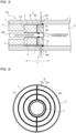
- Fig. 6 is a diagram schematically illustrating the end surface of the outer lid body of the pressure accumulator according to Embodiment 3.
- Constitutional elements identical to the corresponding constitutional elements of the pressure accumulators 100, 101 described in Embodiments 1 and 2 are given the same reference symbols, and the description of such constitutional elements will be omitted when appropriate.
- a cylindrical body 1 of the pressure accumulator 102 has a first vent hole 1a and a second vent hole 1b, the first vent hole 1a allowing the outside of a cylindrical body 1 to communicate with a gap S to inject gas for heat exchange into the gap S from the outside of the cylindrical body 1, the second vent hole 1b allowing the outside of the cylindrical body 1 to communicate with the gap S to discharge the gas injected into the gap S through the first vent hole 1a to the outside of the cylindrical body 1.
- An injection pipe 300 through which gas is injected is connected to the first vent hole 1a.
- a discharge pipe 400 through which gas is discharged is connected to the second vent hole 1b.
- the gas is inert air, and it is preferable to use dehumidified gas if possible.
- the gas may be an inert gas, or may be other gases.
- the gas is injected into the gap S by being pressurized by a power device, such as a compressor, circulates through the gap S, and is then discharged to the outside of the cylindrical body 1.
- a power device such as a compressor
- the gas layer forms a heat-insulating layer, thus increasing an effect of suppressing heat conduction from the lid body 2 to the cylindrical body 1.
- the leaked hydrogen gas can be discharged through the second vent hole 1b.
- the lid body 2 includes an inner lid body 20 and an outer lid body 21, the inner lid body 20 being made of austenitic stainless steel, and being disposed at a position close to the storage space of the cylindrical body 1, the outer lid body 21 being made of low alloy steel, and being disposed at a position close to a fixing part.
- the end surface of the outer lid body 21 has a groove portion 24 that causes gas injected into the gap S from the outside of the cylindrical body 1 to circulate on the end surface of the outer lid body 21.
- the groove portion 24 includes a plurality of annular groove portions 24a and a straight-line-shaped coupling groove portion 24b that connects the plurality of annular groove portions 24a to each other.
- the plurality of annular groove portions 24a are formed by three circles that enclose the outer periphery of the through hole 21a. The three circles are formed such that large circles enclose the outer periphery of a small circle at substantially equal intervals.
- the coupling groove portion 24b has both end portions thereof communicating with the gap S, and is formed to extend in the radial direction in such a way as to connect the three circles to each other.
- Gas injected into the gap S enters the coupling groove portion 24b from one end portion of the coupling groove portion 24b and flows through the annular groove portions 24a and, thereafter, is discharged to the gap S from the other end of the coupling groove portion 24b.
- the gas injected into the gap S from the outside of the cylindrical body 1 circulates through the groove portion 24 as described above and hence, the gas layer forms a heat-insulating layer, thus increasing an effect of suppressing heat conduction from the inner lid body 20 to the outer lid body 21.
- gas is dry air, even if the temperature of the gas is lowered at the time of performing heat exchange, dew condensation and freezing will not occur in the groove portion 24 of the lid body 21.
- the end surface of the inner lid body 20 and the end surface of the outer lid body 21 that face each other may have the groove portion 24. Further, of the end surface of the inner lid body 20 and the end surface of the outer lid body 21 that face each other, each of both end surfaces may have the groove portion 24.
- the groove portion 24 is not limited to the shape shown in the drawing.
- the annular groove portions 24a are not limited to a circular shape, and may have a rectangular shape or other shapes.
- the coupling groove portion 24b is not limited to a straight line shape, and may have a curved shape, a zigzag shape, or other shapes.
- the groove portion 24 may have, for example, a lattice shape or a spiral shape, or may have other shapes.
- the groove portion 24 may have any shape.
- the pressure accumulator 102 it is desirable that, of the end surface of the inner lid body 20 and the end surface of the outer lid body 21 that face each other, either one of the end surface of the inner lid body 20 or the end surface of the outer lid body 21 or both of the end surface of the inner lid body 20 and the end surface of the outer lid body 21 be provided with the groove portion 24.
- the groove portion 24 is not always necessary to be provided, and may be omitted.
- the pressure accumulator 102 is also applicable to a configuration in which the lid body 2 is made of only austenitic stainless steel. However, in this case, the groove portion 24 shown in Fig. 5 and Fig. 6 is omitted.
- the pressure accumulator 102 may be configured to perform a control of determining conditions of gas to be injected into the gap S based on the detected value from the temperature detection unit 5. Examples of conditions of gas include flow rate, flow velocity, injection time, and the like. The pressure accumulator 102 is not always necessary to determine the conditions of gas to be injected into the gap S based on the detected value from the temperature detection unit 5, and may determine the conditions of gas to be injected into the gap S by using other detection units.
- the pressure accumulators (100, 100A, 101, 101A, 102) have been described based on Embodiments heretofore. However, the pressure accumulators (100, 100A, 101, 101A, 102) are not limited to the configurations of the above-described Embodiments. The configurations of the above-mentioned pressure accumulators (100, 100A, 101, 101A, 102) are merely examples, and may include other constitutional elements. In short, the pressure accumulators (100, 100A, 101, 101A, 102) include variations to which design changes or applications are normally added by those who are skilled in the art without departing from the technical concept.
- 1 cylindrical body, 1a: first vent hole, 1b: second vent hole, 2: lid body, 2a: through hole, 3: sealing structure portion, 4: fixing part, 5: temperature detection unit, 6: sealing part, 7, 8, 9: heat insulating part, 10: storage space, 11: female screw portion, 20: inner lid body, 20a: through hole, 21: outer lid body, 21a: through hole, 22: screw fastening portion, 23: welding-fixing portion, 24: groove portion, 24a: annular groove portion, 24b: coupling groove portion, 100, 100A, 101, 101A, 102: pressure accumulator, 200: pipe, 300: injection pipe, 400: discharge pipe, S: gap.
Landscapes
- Engineering & Computer Science (AREA)
- Mechanical Engineering (AREA)
- General Engineering & Computer Science (AREA)
- Physics & Mathematics (AREA)
- Fluid Mechanics (AREA)
- Filling Or Discharging Of Gas Storage Vessels (AREA)
- Supply Devices, Intensifiers, Converters, And Telemotors (AREA)
- Braking Systems And Boosters (AREA)
Abstract
Description
- The present disclosure relates to a pressure accumulator that stores vaporized liquefied gas.
- Conventionally, there are various known pressure accumulators that store vaporized liquefied gas therein, and that are already put into practice. In general, liquefied hydrogen that is carried by a liquid hydrogen lorry and that is stored in a storage tank is vaporized by a vaporizer, and is compressed by a compressor into a high pressure and, thereafter, is injected into a pressure accumulator through a pipe. A hydrogen gas pressure accumulator disclosed in the following Patent Literature 1, for example, is configured to include a cylindrical cylinder portion, lid portions, and threaded portions, the cylindrical cylinder portion being made of steel and being configured to store vaporized liquefied gas in the cylindrical cylinder portion, the lid portions being configured to hermetically seal both end portions of the cylindrical cylinder portion in an openable manner, the threaded portions being configured to fix the lid portions to the cylindrical cylinder portion.
- Patent Literature 1:
Japanese Unexamined Patent Application Publication No. 2019-82188 - Adopting a configuration can be considered in which liquefied gas at a very low temperature is injected into a pressure accumulator from the outside through a pipe, and is vaporized therein and is stored in the pressure accumulator, so that a vaporizer is not necessary. However, in the hydrogen gas pressure accumulator disclosed in Patent Literature 1, although the cylindrical cylinder can withstand only approximately - 30 degrees C, for example, the temperature of liquid hydrogen is approximately -260 degrees C and hence, there is a possibility that the temperature of the lid portion is lowered due to the heat conduction caused by liquid hydrogen at a very low temperature flowing through the pipe, thus lowering the temperature of the cylindrical cylinder to which heat is conducted from the lid portion, causing a brittle fracture in the cylindrical ring.
- The present disclosure has been made to solve the above-mentioned problem, and it is an object of the present disclosure to provide a pressure accumulator that can vaporize and store liquefied gas without causing a brittle fracture in the cylindrical body even when liquefied gas at a very low temperature is injected into the pressure accumulator from the outside through a pipe.
- A pressure accumulator according to an embodiment of the present disclosure is a pressure accumulator that causes a liquefied gas at a very low temperature to be injected into the pressure accumulator from an outside through a pipe to vaporize and store the liquefied gas, the pressure accumulator including: a cylindrical body made of metal and configured to vaporize and store the liquefied gas in a storage space in the cylindrical body; a lid body having a through hole that allows the pipe to penetrate through the through hole, the lid body being configured to fix the pipe passing through the through hole, and being configured to close an opening end portion of the cylindrical body with a gap provided between the lid body and an inner peripheral surface of the cylindrical body, the gap communicating with the storage space of the cylindrical body; a sealing structure portion provided between an outer peripheral portion of the lid body and an inner peripheral portion of the cylindrical body, the sealing structure portion being configured to fill in at least a portion of the gap; and a fixing part provided at the opening end portion of the cylindrical body, an outer peripheral surface of the fixing part being screw fastened to the inner peripheral surface of the cylindrical body to support and fix the lid body from an outer side of the lid body.
- According to the embodiment of the present disclosure, the gap is provided between the outer peripheral portion of the lid body and the inner peripheral portion of the cylindrical body, and at least a portion of the gap is filled with the sealing structure portion and hence, the gap serves as a heat-insulating layer, thus suppressing heat conduction from the lid body to the cylindrical body and suppressing a brittle fracture in the cylindrical body. Accordingly, by causing liquefied gas at a very low temperature to be injected into the pressure accumulator from the outside through a pipe, it is possible to vaporize and store the liquefied gas.
-
- [
Fig. 1] Fig. 1 is a cross-sectional view schematically showing the internal structure of one end of a pressure accumulator according to Embodiment 1. - [
Fig. 2] Fig. 2 is a cross-sectional view schematically showing the internal structure of one end of a modification of the pressure accumulator according to Embodiment 1. - [
Fig. 3] Fig. 3 is a cross-sectional view schematically showing the internal structure of one end of a pressure accumulator according toEmbodiment 2. - [
Fig. 4] Fig. 4 is a cross-sectional view schematically showing the internal structure of one end of a modification of the pressure accumulator according toEmbodiment 2. - [
Fig. 5] Fig. 5 is a cross-sectional view schematically showing the internal structure of one end of a pressure accumulator according toEmbodiment 3. - [
Fig. 6] Fig. 6 is a diagram schematically illustrating an end surface of an outer lid body of the pressure accumulator according toEmbodiment 3. - Hereinafter, Embodiments will be described with reference to drawings. In the respective drawings, identical or corresponding components are given the same reference symbols, and the description of such components is omitted or simplified when appropriate. The shapes, the sizes, the arrangement, and the like of the components described in the respective drawings may be suitably changed within the scope of the present disclosure.
-
Fig. 1 is a cross-sectional view schematically showing the internal structure of one end of a pressure accumulator according to Embodiment 1. Apressure accumulator 100 according to Embodiment 1 causes liquefied gas at a very low temperature to be injected into thepressure accumulator 100 from the outside through apipe 200 to vaporize and store the liquefied gas. In Embodiment 1, the description will be made by taking, as an example, the case in which the liquid gas is liquefied hydrogen, for example. Liquefied hydrogen at a very low temperature is at approximately -260 degrees C, for example. The liquid gas is not limited to liquefied hydrogen, and may be liquid nitrogen or liquid helium, for example. In the case in which the liquid gas is liquefied hydrogen, thepressure accumulator 100 is installed at a hydrogen station or the like at which hydrogen is supplied to vehicles, for example. - As shown in
Fig. 1 , thepressure accumulator 100 includes a cylindrical body 1 made of metal, alid body 2 that closes the opening end portion of the cylindrical body 1, asealing structure portion 3 provided between the outer peripheral portion of thelid body 2 and the inner peripheral portion of the cylindrical body 1, a fixing part 4 that supports and fixes thelid body 2 from the outer side of thelid body 2, and atemperature detection unit 5. - The cylindrical body 1 is configured to vaporize liquefied hydrogen in a
storage space 10 in the cylindrical body 1 to store hydrogen gas therein. The inner wall surface of thepressure accumulator 100 is a portion that comes into contact with liquefied hydrogen and hydrogen gas. A liquefied gas at a very low temperature is injected into thestorage space 10 of the cylindrical body 1 from the outside through thepipe 200. Thepipe 200 is made of austenitic stainless steel, for example. The reason is that austenitic stainless steel is excellent in brittleness resistance against liquid hydrogen, and can ensure strength against very low temperatures. Hydrogen gas stored in thestorage space 10 of the cylindrical body 1 is supplied to vehicles or the like through a pipe communicating with the outside. - The cylindrical body 1 is made of low alloy steel, for example. Examples of the low alloy steel include chromium-molybdenum steel, nickel-chromium-molybdenum steel, manganese-chromium steel, manganese steel, or boron-added steel. The cylindrical body 1 has a cylindrical shape having both ends open, and a
female screw portion 11 is formed on the inner peripheral surface at each of both end portions of the cylindrical body 1. The cylindrical body 1 may have a bottomed cylindrical shape having only one end open, for example. Alternatively, the cylindrical body 1 is not limited to a cylindrical shape, and may have any of other shapes, such as a square cylindrical shape. The outer surface of the cylindrical body 1 may be covered by carbon fiber reinforced plastics (CFRP), being a material other than metal. From the viewpoint of vaporization efficiency, the ratio in wall thickness between a CFRP layer and the cylindrical body 1 (the thickness of the CFRP layer/the thickness of the cylindrical body 1) is preferably 50% or less, and is more preferably 25% or less. The reason is that when the CFRP layer has an excessively large wall thickness, a heat insulating effect becomes conspicuous, thus lowering the vaporization efficiency of liquefied hydrogen. - The
lid body 2 closes the opening end portion of the cylindrical body 1. Thelid body 2 is made of austenitic stainless steel, and includes aninner lid body 20 and anouter lid body 21, theinner lid body 20 being disposed at a position close to thestorage space 10 of the cylindrical body 1, theouter lid body 21 being made of low alloy steel, and being disposed at a position close to the fixing part 4 of the cylindrical body 1. Theinner lid body 20 has a throughhole 20a that allows thepipe 200 to penetrate therethrough, and thepipe 200 that penetrates through the throughhole 20a is fixed to theinner lid body 20. Theouter lid body 21 has a throughhole 21a that allows thepipe 200 to penetrate therethrough. - The
inner lid body 20 faces thestorage space 10 of the cylindrical body 1, and is always in a state of being exposed to liquid hydrogen at a very low temperature. However, theinner lid body 20 is made of austenitic stainless steel, thus being excellent in brittleness resistance against liquid hydrogen, and ensuring strength against very low temperatures. Provided that theinner lid body 20 is excellent in brittleness resistance against liquid hydrogen and can withstand very low temperatures, theinner lid body 20 may be made of other materials. Theinner lid body 20 has a length of approximately 30 mm in an axial direction X of the cylindrical body 1, for example. The reason is that a length of approximately 30 mm allows theinner lid body 20 to have sufficient strength against liquid hydrogen. However, the length of theinner lid body 20 is not limited to approximately 30 mm, and is designed by suitably changing the length of theinner lid body 20 according to the size and the shape of the cylindrical body 1. - The
inner lid body 20 includes ascrew fastening portion 22 that causes thepipe 200 passing through the throughhole 20a to be fixed by screw fastening. Specifically, a female screw is formed at the inner peripheral portion of the throughhole 20a of theinner lid body 20, and a male screw that is fastened to the female screw of theinner lid body 20 is formed at the outer peripheral portion of thepipe 200. By causing theinner lid body 20 and thepipe 200 to be screw fastened to each other, it is possible to surely fix thepipe 200 against the internal pressure of hydrogen gas stored in thestorage space 10 of the cylindrical body 1. - A sealing
part 6 is provided between the inner peripheral portion of theinner lid body 20 and the outer peripheral portion of thepipe 200. This is to prevent a situation in which hydrogen gas stored in thestorage space 10 of the cylindrical body 1 leaks to the outside through a space formed between the inner peripheral portion of theinner lid body 20 and the outer peripheral portion of thepipe 200. The sealingpart 6 may be an O-ring, for example. However, the sealingpart 6 is not limited to the O-ring. Provided that the sealingpart 6 can prevent a situation in which hydrogen gas stored in thestorage space 10 of the cylindrical body 1 leaks through a space formed between the inner peripheral portion of theinner lid body 20 and the outer peripheral portion of thepipe 200, the sealingpart 6 may be formed by other members. - The
inner lid body 20 is fitted in the opening end portion of the cylindrical body 1 with a gap S provided between theinner lid body 20 and the inner peripheral surface of the cylindrical body 1, the gap S communicating with thestorage space 10 of the cylindrical body 1. The gap S is set to approximately 0.5 mm, for example, and is provided along the axial direction X of the cylindrical body 1. By causing the gap S to serve as a heat-insulating layer, it is possible to suppress a situation in which the temperature of the cylindrical body 1 is lowered by theinner lid body 20 having a low temperature due to the heat conduction from thepipe 200 through which liquid hydrogen at a very low temperature passes. Further, by providing the gap S, it is possible to fit theinner lid body 20 into the opening end portion of the cylindrical body 1. - The
outer lid body 21 is provided to increase strength against the internal pressure of hydrogen gas in the cylindrical body 1. The reason is that there may be a case in which only theinner lid body 20 having a length of approximately 30 mm in the axial direction X cannot obtain sufficient strength against the internal pressure of hydrogen gas. Theouter lid body 21 is made of low alloy steel, such as chromium-molybdenum steel, nickel-chromium-molybdenum steel, manganese-chromium steel, manganese steel, or boron-added steel. The low alloy steel is a lower cost than austenitic stainless steel, thus contributing to a reduction in manufacturing costs. The material of theouter lid body 21 is not limited to low alloy steel. Provided that theouter lid body 21 can increase strength against the internal pressure of hydrogen gas stored in thestorage space 10 of the cylindrical body 1, theouter lid body 21 may be made of other materials. - A
heat insulating part 7 is provided between theinner lid body 20 and theouter lid body 21. This is to prevent heat conduction from theinner lid body 20 to theouter lid body 21. Aheat insulating part 8 is also provided between theouter lid body 21 and thepipe 200. This is to prevent heat conduction of the very low temperature of thepipe 200 to theouter lid body 21, liquid hydrogen at a very low temperature passing through thepipe 200. The reason is that when the temperature of theouter lid body 21, which is made of low alloy steel, is lowered due to the heat conduction of very low temperatures, there is a possibility of occurrence of a brittle fracture in theouter lid body 21. An example of the material of theheat insulating parts - The sealing
structure portion 3 is provided between the outer peripheral portion of theinner lid body 20 and the inner peripheral portion of the cylindrical body 1 to fill in at least a portion of the gap S. The sealingstructure portion 3 is a sealing part made of a resin or metal, such as an O-ring, for example. By providing the sealingstructure portion 3, it is possible to prevent a situation in which hydrogen gas stored in thestorage space 10 of the cylindrical body 1 leaks to the outside through the gap S. Filling in at least a portion of the gap S refers to filling in the entire gap S or filling in a portion of the gap S. It is preferable that, as shown in the drawing, a portion of the gap S be the end portion of the gap S at a position close to thestorage space 10 of the cylindrical body 1. However, a portion of the gap S may be the end portion of the gap S at a position close to theouter lid body 21 or may be an intermediate portion of the gap S, for example. The sealingstructure portion 3 is not limited to an O-ring. Provided that the sealingstructure portion 3 can prevent hydrogen gas stored in thestorage space 10 of the cylindrical body 1 from flowing into the gap S formed between the outer peripheral portion of theinner lid body 20 and the inner peripheral portion of the cylindrical body 1, the sealingstructure portion 3 may be formed by other members. For example, the sealingstructure portion 3 may be a member, such as a metal hollow O-ring that can provide sealing by a combination of metal and a resin. In the case in which an O-ring made of a resin is used, it is preferable to use an O-ring with a cold temperature limit of -30 degrees C or less, and it is more preferable to use an O-ring with a cold temperature limit of -50 degrees C or less. - The fixing part 4 is provided at the opening end portion of the cylindrical body 1, and the outer peripheral surface of the fixing part 4 is screw fastened to the inner peripheral surface of the cylindrical body 1 to support and fix the
lid body 2 from the outer side of thestorage space 10. Specifically, the fixing part 4 is a gland nut having an outer peripheral surface thereof provided with a male screw portion that is to be screw fastened to thefemale screw portion 11 of the cylindrical body 1. When the fixing part 4 is screw fastened to the cylindrical body 1, the position of the fixing part 4 in the axial direction X is fixed. One end surface of the fixing part 4 abuts against the outer surface of theouter lid body 21 of thelid body 2 on which an axial force in the axial direction X acts due to high-pressure hydrogen gas stored in thestorage space 10, so that the fixing part 4 can support thelid body 2. Thepipe 200 passes through the hollow hole of the fixing part 4. The thickness of the fixing part 4 in the radial direction may be suitably determined. However, the fixing part 4 has a structure that supports pressure received by theinner lid body 20 and hence, when the fixing part 4 has an extremely small wall thickness in the radial direction, the fixing part 4 cannot sufficiently support thelid body 2. For this reason, the thickness of the fixing part 4 in the radial direction is preferably set to a wall thickness that can ensure an area capable of supporting 40% or more of the area of theinner lid body 20 that receives pressure, and is more preferably set to a wall thickness that can ensure an area capable of supporting 60% or more of the area of theinner lid body 20 that receives pressure. For example, assuming that the diameter of theinner lid body 20 is 300 mm, the area of theinner lid body 20 that receives pressure is 70650 mm2. The area of theinner lid body 20 is calculated in a state that includes a portion in which thepipe 200 penetrates. However, in an actual calculation, it is desirable to perform the calculation in a state that excludes the portion in which thepipe 200 penetrates. In contrast, assuming that the wall thickness of the fixing part 4 is 50 mm, an area supported by the fixing part 4 is 39250 mm2. In this case, the fixing part 4 can ensure an area capable of supporting 56% of the area of theinner lid body 20 that receives pressure. - The
temperature detection unit 5 may be a thermocouple, for example, and detects the temperature of hydrogen gas stored in thestorage space 10 of the cylindrical body 1, or the temperature of theinner lid body 20. In thepressure accumulator 100 according to Embodiment 1, the temperature of hydrogen gas stored in the cylindrical body 1 or the temperature of theinner lid body 20 is monitored by using thetemperature detection unit 5. In thepressure accumulator 100, conditions of liquid hydrogen to be injected from thepipe 200 are determined based on the detected value from thetemperature detection unit 5. The conditions of liquid hydrogen include flow rate, flow velocity, injection time, and the like. Thepressure accumulator 100 includes a control unit, and is configured such that the control unit determines conditions of liquid hydrogen based on the detected value from thetemperature detection unit 5 to adjust the flow rate and the like of liquefied hydrogen that passes through thepipe 200. Although it is desirable for thepressure accumulator 100 to be provided with thetemperature detection unit 5, thetemperature detection unit 5 is not always necessary to be provided, and may be omitted. -
Fig. 2 is a cross-sectional view schematically showing the internal structure of one end of a modification of the pressure accumulator according to Embodiment 1. In thepressure accumulator 100 shown inFig. 1 , theinner lid body 20 includes thescrew fastening portion 22 that causes thepipe 200 passing through the throughhole 20a to be fixed by screw fastening. In contrast, in apressure accumulator 100A shown inFig. 2 , theinner lid body 20 is configured to include a welding-fixingportion 23 that causes thepipe 200 passing through the throughhole 20a to be fixed by welding. The welding-fixingportion 23 may be provided to the entireinner lid body 20 along the axial direction X, or may be provided to a portion of theinner lid body 20 along the axial direction X. In this case, a space formed between the inner peripheral portion of theinner lid body 20 and the outer peripheral portion of thepipe 200 is completely closed and hence, the sealingpart 6 shown inFig. 1 is unnecessary. - Adopting a configuration can be considered in which liquefied gas at a very low temperature is injected into the
pressure accumulator 100 from the outside through thepipe 200, and is vaporized therein and is stored in thepressure accumulator 100, so that a vaporizer is not necessary. However, although the cylindrical body 1 can withstand only approximately -30 degrees C, for example, the temperature of liquid hydrogen is approximately -260 degrees C, for example. Accordingly, when liquid hydrogen is injected into thepressure accumulator 100, the temperature of thelid body 2 is lowered due to the heat conduction caused by the liquid hydrogen at a very low temperature that flows through thepipe 200, thus causing the temperature of the cylindrical body 1 to be lowered due to the heat conduction from thelid body 2 and hence, there is a possibility of occurrence of a brittle fracture in the cylindrical body 1. - In view of the above, as described above, the
pressure accumulator 100 according to Embodiment 1 includes the cylindrical body 1 made of metal and thelid body 2, the cylindrical body 1 being configured to vaporize and store liquefied gas in thestorage space 10 in the cylindrical body 1, thelid body 2 having the throughholes pipe 200 to penetrate therethrough, thelid body 2 fixing thepipe 200 passing through the throughholes lid body 2 closing the opening end portion of the cylindrical body 1 with the gap S formed between thelid body 2 and the inner peripheral surface of the cylindrical body 1, the gap S communicating with thestorage space 10 of the cylindrical body 1. Thepressure accumulator 100 according to Embodiment 1 also includes the sealingstructure portion 3 and the fixing part 4, the sealingstructure portion 3 being provided between the outer peripheral portion of thelid body 2 and the inner peripheral portion of the cylindrical body 1 to fill in at least a portion of the gap S, the fixing part 4 being provided at the opening end portion of the cylindrical body 1, the outer peripheral surface of the fixing part 4 being screw fastened to the inner peripheral surface of the cylindrical body 1 to support and fix thelid body 2 from the outer side of thelid body 2. - As described above, in the
pressure accumulator 100 according to Embodiment 1, the gap S is provided between the outer peripheral portion of thelid body 2 and the inner peripheral portion of the cylindrical body 1, and at least a portion of the gap S is filled by the sealingstructure portion 3 and hence, the gap S serves as a heat-insulating layer, thus suppressing heat conduction from thelid body 2 to the cylindrical body 1. That is, it is possible to suppress a situation in which the temperature of the cylindrical body 1 is lowered by thelid body 2 having a low temperature due to the heat conduction from thepipe 200 through which liquid hydrogen at a very low temperature passes and hence, a brittle fracture in the cylindrical body 1 can be suppressed. Accordingly, by causing liquefied gas at a very low temperature to be injected into thepressure accumulator 100 according to Embodiment 1 from the outside through thepipe 200, it is possible to vaporize and store the liquefied gas in thepressure accumulator 100. - The
lid body 2 includes thescrew fastening portion 22 that causes thepipe 200 passing through the throughholes part 6 that closes a space formed between the inner peripheral portion of thelid body 2 and the outer peripheral portion of thepipe 200 is provided between the inner peripheral portion of thelid body 2 and the outer peripheral portion of thepipe 200. Accordingly, it is possible to surely fix thepipe 200 against the internal pressure of hydrogen gas stored in thestorage space 10 of the cylindrical body 1. It is also possible to prevent a situation in which hydrogen gas stored in thestorage space 10 of the cylindrical body 1 leaks to the outside through a space formed between the inner peripheral portion of theinner lid body 20 and the outer peripheral portion of thepipe 200. - The
lid body 2 includes theinner lid body 20 and theouter lid body 21, theinner lid body 20 being made of austenitic stainless steel, and being disposed at a position close to thestorage space 10 of the cylindrical body 1, theouter lid body 21 being made of low alloy steel, and being disposed at a position close to the fixing part 4. Accordingly, although theinner lid body 20 faces thestorage space 10 of the cylindrical body 1, and is always in a state of being exposed to liquid hydrogen at a very low temperature, theinner lid body 20 is made of austenitic stainless steel, thus being excellent in brittleness resistance against liquid hydrogen, and ensuring strength against very low temperatures. Strength against the internal pressure of hydrogen gas in the cylindrical body 1 can be increased by theouter lid body 21. Further, using low alloy steel that is a lower cost than austenitic stainless steel contributes to a reduction in manufacturing costs. - The
heat insulating part 7 is provided between theinner lid body 20 and theouter lid body 21, and theheat insulating part 8 is provided between theouter lid body 21 and thepipe 200. Accordingly, heat conduction from theinner lid body 20 to theouter lid body 21 can be prevented, and it is also possible to prevent a situation in which the very low temperature of thepipe 200 through which liquid hydrogen at a very low temperature passes is conducted to theouter lid body 21 and hence, it is possible to prevent brittle damage of theouter lid body 21 caused by the lowering of the temperature. - Each of the
pressure accumulators temperature detection unit 5 configured to detect the temperature of liquefied gas, which is vaporized, stored in thestorage space 10 of the cylindrical body 1, or the temperature of thelid body 2. Accordingly, in thepressure accumulators inner lid body 20 can be monitored by using thetemperature detection unit 5, and it is possible to determine conditions of liquid hydrogen to be injected from thepipe 200 based on the detected value from thetemperature detection unit 5. - Next, a
pressure accumulator 101 according toEmbodiment 2 will be described with reference toFig. 3. Fig. 3 is a cross-sectional view schematically showing the internal structure of one end of the pressure accumulator according toEmbodiment 2. Constitutional elements identical to the corresponding constitutional elements of thepressure accumulator 100 described in Embodiment 1 are given the same reference symbols, and the description of such constitutional elements will be omitted when appropriate. - The
pressure accumulator 101 according toEmbodiment 2 differs from thepressure accumulator 100 described in the above-mentioned Embodiment 1 in the configuration of thelid body 2. Alid body 2 of thepressure accumulator 101 according toEmbodiment 2 is made of only austenitic stainless steel. - The
lid body 2 includes ascrew fastening portion 22 that causes apipe 200 passing through a throughhole 2a to be fixed by screw fastening. Specifically, a female screw is formed at the inner peripheral portion of the throughhole 2a of thelid body 2, and a male screw that is fastened to the screw of thelid body 2 is formed at the outer peripheral portion of thepipe 200. Thelid body 2 includes thescrew fastening portion 22 that causes thelid body 2 to be screw fastened to thepipe 200 and hence, it is possible to surely fix thepipe 200 against the internal pressure of hydrogen gas stored in thestorage space 10 of the cylindrical body 1. - A sealing
part 6 that closes a space formed between the inner peripheral portion of thelid body 2 and the outer peripheral portion of thepipe 200 is provided between the inner peripheral portion of thelid body 2 and the outer peripheral portion of thepipe 200. This is to prevent a situation in which hydrogen gas stored in thestorage space 10 of the cylindrical body 1 leaks to the outside through a gap formed between the inner peripheral portion of thelid body 2 and the outer peripheral portion of thepipe 200. The sealingpart 6 may be an O-ring, for example. However, the sealingpart 6 is not limited to an O-ring. Provided that the sealingpart 6 can prevent a situation in which hydrogen gas stored in thestorage space 10 of the cylindrical body 1 leaks through a gap formed between the inner peripheral portion of thelid body 2 and the outer peripheral portion of thepipe 200, the sealingpart 6 may be formed by other members. - A
heat insulating part 9 is provided between thelid body 2 and the fixing part 4. This is to prevent heat conduction from thelid body 2 to the fixing part 4. The reason is that when the temperature of the fixing part 4 is lowered due to the heat conduction of very low temperatures, there is a possibility of occurrence of a brittle fracture in the fixing part 4. An example of the material of theheat insulating part 9 is ceramic. However, in the case in which thelid body 2 has a large length in the axial direction, so that heat conduction from thelid body 2 to the fixing part 4 will not occur, theheat insulating part 9 may be omitted. -
Fig. 4 is a cross-sectional view schematically showing the internal structure of one end of a modification of the pressure accumulator according toEmbodiment 2. In thepressure accumulator 101 shown inFig. 3 , thelid body 2 includes thescrew fastening portion 22 that causes thepipe 200 passing through the throughhole 2a to be fixed by screw fastening. In contrast, in apressure accumulator 101A shown inFig. 4 , thelid body 2 is configured to include a welding-fixingportion 23 that causes thepipe 200 passing through the throughhole 2a to be fixed by welding. The welding-fixingportion 23 may be provided to theentire lid body 2 along the axial direction X, or may be provided to a portion of thelid body 2 along the axial direction X. In this case, a space formed between the inner peripheral portion of thelid body 2 and the outer peripheral portion of thepipe 200 is completely closed and hence, the sealingpart 6 shown inFig. 3 is unnecessary. - As described above, also in each of the
pressure accumulators Embodiment 2, the gap S is provided between the outer peripheral portion of thelid body 2 and the inner peripheral portion of the cylindrical body 1, and at least a portion of the gap S is filled by the sealingstructure portion 3 and hence, the gap S serves as a heat-insulating layer, thus suppressing heat conduction from thelid body 2 to the cylindrical body 1. That is, it is possible to suppress a situation in which the temperature of the cylindrical body 1 is lowered by thelid body 2 having a low temperature due to the heat conduction from thepipe 200 through which liquid hydrogen at a very low temperature passes. Accordingly, by causing liquefied gas at a very low temperature to be injected into thepressure accumulator 101 according toEmbodiment 2 from the outside through thepipe 200, it is possible to vaporize and store the liquefied gas in thepressure accumulator 101. - The
lid body 2 is made of austenitic stainless steel. Accordingly, although thelid body 2 faces thestorage space 10 of the cylindrical body 1, and is always in a state of being exposed to liquid hydrogen at a very low temperature, thelid body 2 is made of austenitic stainless steel, thus being excellent in brittleness resistance against liquid hydrogen, and ensuring strength against very low temperatures. - Each of the
pressure accumulators Embodiment 2 includes aheat insulating part 9 provided between thelid body 2 and the fixing part 4. Accordingly, heat conduction from thelid body 2 to the fixing part 4 can be prevented and hence, it is possible to prevent brittle damage of the fixing part 4 caused by the lowering of the temperature. - Next, a
pressure accumulator 102 according toEmbodiment 3 will be described with reference toFig. 5 and Fig. 6. Fig. 5 is a cross-sectional view schematically showing the internal structure of one end of the pressure accumulator according toEmbodiment 3.Fig. 6 is a diagram schematically illustrating the end surface of the outer lid body of the pressure accumulator according toEmbodiment 3. Constitutional elements identical to the corresponding constitutional elements of thepressure accumulators Embodiments 1 and 2 are given the same reference symbols, and the description of such constitutional elements will be omitted when appropriate. - As shown in
Fig. 5 , a cylindrical body 1 of thepressure accumulator 102 according toEmbodiment 3 has afirst vent hole 1a and asecond vent hole 1b, thefirst vent hole 1a allowing the outside of a cylindrical body 1 to communicate with a gap S to inject gas for heat exchange into the gap S from the outside of the cylindrical body 1, thesecond vent hole 1b allowing the outside of the cylindrical body 1 to communicate with the gap S to discharge the gas injected into the gap S through thefirst vent hole 1a to the outside of the cylindrical body 1. Aninjection pipe 300 through which gas is injected is connected to thefirst vent hole 1a. Adischarge pipe 400 through which gas is discharged is connected to thesecond vent hole 1b. An example of the gas is inert air, and it is preferable to use dehumidified gas if possible. The gas may be an inert gas, or may be other gases. The gas is injected into the gap S by being pressurized by a power device, such as a compressor, circulates through the gap S, and is then discharged to the outside of the cylindrical body 1. In thepressure accumulator 102 according toEmbodiment 3, by causing gas to flow into the gap S, the gas layer forms a heat-insulating layer, thus increasing an effect of suppressing heat conduction from thelid body 2 to the cylindrical body 1. In thepressure accumulator 102, even if a situation occurs in which hydrogen gas stored in thestorage space 10 of the cylindrical body 1 leaks to a portion of the gap S, the leaked hydrogen gas can be discharged through thesecond vent hole 1b. - The
lid body 2 includes aninner lid body 20 and anouter lid body 21, theinner lid body 20 being made of austenitic stainless steel, and being disposed at a position close to the storage space of the cylindrical body 1, theouter lid body 21 being made of low alloy steel, and being disposed at a position close to a fixing part. Of the end surface of theinner lid body 20 and the end surface of theouter lid body 21 that face each other, the end surface of theouter lid body 21 has agroove portion 24 that causes gas injected into the gap S from the outside of the cylindrical body 1 to circulate on the end surface of theouter lid body 21. - In
Fig. 6 , thick line portions show thegroove portion 24. As shown inFig. 6 , thegroove portion 24 includes a plurality ofannular groove portions 24a and a straight-line-shapedcoupling groove portion 24b that connects the plurality ofannular groove portions 24a to each other. In the case of the example shown in the drawing, the plurality ofannular groove portions 24a are formed by three circles that enclose the outer periphery of the throughhole 21a. The three circles are formed such that large circles enclose the outer periphery of a small circle at substantially equal intervals. Thecoupling groove portion 24b has both end portions thereof communicating with the gap S, and is formed to extend in the radial direction in such a way as to connect the three circles to each other. Gas injected into the gap S enters thecoupling groove portion 24b from one end portion of thecoupling groove portion 24b and flows through theannular groove portions 24a and, thereafter, is discharged to the gap S from the other end of thecoupling groove portion 24b. The gas injected into the gap S from the outside of the cylindrical body 1 circulates through thegroove portion 24 as described above and hence, the gas layer forms a heat-insulating layer, thus increasing an effect of suppressing heat conduction from theinner lid body 20 to theouter lid body 21. When gas is dry air, even if the temperature of the gas is lowered at the time of performing heat exchange, dew condensation and freezing will not occur in thegroove portion 24 of thelid body 21. - Although not shown in the drawing, of the end surface of the
inner lid body 20 and the end surface of theouter lid body 21 that face each other, the end surface of theinner lid body 20 may have thegroove portion 24. Further, of the end surface of theinner lid body 20 and the end surface of theouter lid body 21 that face each other, each of both end surfaces may have thegroove portion 24. - The
groove portion 24 is not limited to the shape shown in the drawing. For example, theannular groove portions 24a are not limited to a circular shape, and may have a rectangular shape or other shapes. Thecoupling groove portion 24b is not limited to a straight line shape, and may have a curved shape, a zigzag shape, or other shapes. Further, thegroove portion 24 may have, for example, a lattice shape or a spiral shape, or may have other shapes. In short, provided that thegroove portion 24 can cause gas injected into the gap S from the outside of the cylindrical body 1 to circulate through the end surface of theinner lid body 20 or the end surface of theouter lid body 21, thegroove portion 24 may have any shape. - In the
pressure accumulator 102, it is desirable that, of the end surface of theinner lid body 20 and the end surface of theouter lid body 21 that face each other, either one of the end surface of theinner lid body 20 or the end surface of theouter lid body 21 or both of the end surface of theinner lid body 20 and the end surface of theouter lid body 21 be provided with thegroove portion 24. However, thegroove portion 24 is not always necessary to be provided, and may be omitted. - As shown in
Fig. 3 and Fig. 4 , for example, thepressure accumulator 102 is also applicable to a configuration in which thelid body 2 is made of only austenitic stainless steel. However, in this case, thegroove portion 24 shown inFig. 5 and Fig. 6 is omitted. - The
pressure accumulator 102 may be configured to perform a control of determining conditions of gas to be injected into the gap S based on the detected value from thetemperature detection unit 5. Examples of conditions of gas include flow rate, flow velocity, injection time, and the like. Thepressure accumulator 102 is not always necessary to determine the conditions of gas to be injected into the gap S based on the detected value from thetemperature detection unit 5, and may determine the conditions of gas to be injected into the gap S by using other detection units. - The pressure accumulators (100, 100A, 101, 101A, 102) have been described based on Embodiments heretofore. However, the pressure accumulators (100, 100A, 101, 101A, 102) are not limited to the configurations of the above-described Embodiments. The configurations of the above-mentioned pressure accumulators (100, 100A, 101, 101A, 102) are merely examples, and may include other constitutional elements. In short, the pressure accumulators (100, 100A, 101, 101A, 102) include variations to which design changes or applications are normally added by those who are skilled in the art without departing from the technical concept.
- 1: cylindrical body, 1a: first vent hole, 1b: second vent hole, 2: lid body, 2a: through hole, 3: sealing structure portion, 4: fixing part, 5: temperature detection unit, 6: sealing part, 7, 8, 9: heat insulating part, 10: storage space, 11: female screw portion, 20: inner lid body, 20a: through hole, 21: outer lid body, 21a: through hole, 22: screw fastening portion, 23: welding-fixing portion, 24: groove portion, 24a: annular groove portion, 24b: coupling groove portion, 100, 100A, 101, 101A, 102: pressure accumulator, 200: pipe, 300: injection pipe, 400: discharge pipe, S: gap.
Claims (11)
- A pressure accumulator that causes a liquefied gas at a very low temperature to be injected into the pressure accumulator from an outside through a pipe to vaporize and store the liquefied gas, the pressure accumulator comprising:a cylindrical body made of metal and configured to vaporize and store the liquefied gas in a storage space in the cylindrical body;a lid body having a through hole that allows the pipe to penetrate through the through hole, the lid body being configured to fix the pipe passing through the through hole, and being configured to close an opening end portion of the cylindrical body with a gap provided between the lid body and an inner peripheral surface of the cylindrical body, the gap communicating with the storage space of the cylindrical body;a sealing structure portion provided between an outer peripheral portion of the lid body and an inner peripheral portion of the cylindrical body, the sealing structure portion being configured to fill in at least a portion of the gap; anda fixing part provided at the opening end portion of the cylindrical body, an outer peripheral surface of the fixing part being screw fastened to the inner peripheral surface of the cylindrical body to support and fix the lid body from an outer side of the lid body.
- The pressure accumulator of claim 1, wherein the lid body includes a screw fastening portion configured to cause the pipe passing through the through hole to be fixed by screw fastening, and
a sealing part is provided between an inner peripheral portion of the lid body and an outer peripheral portion of the pipe to close a space formed between the inner peripheral portion of the lid body and the outer peripheral portion of the pipe. - The pressure accumulator of claim 1, wherein the lid body includes a welding-fixing portion configured to cause the pipe passing through the through hole to be fixed by welding.
- The pressure accumulator of any one of claims 1 to 3, wherein the lid body is made of austenitic stainless steel.
- The pressure accumulator of any one of claims 1 to 4, further comprising a heat insulating part provided between the lid body and the fixing part.
- The pressure accumulator of any one of claims 1 to 3, wherein
the lid body includesan inner lid body made of austenitic stainless steel, and disposed at a position close to the storage space of the cylindrical body, andan outer lid body made of low alloy steel, and disposed at a position close to the fixing part. - The pressure accumulator of claim 6, wherein a heat insulating part is provided between the inner lid body and the outer lid body, and a heat insulating part is provided between the outer lid body and the pipe.
- The pressure accumulator of any one of claims 1 to 7, further comprising a temperature detection unit configured to detect a temperature of a liquefied gas, which is vaporized, stored in the storage space of the cylindrical body, or a temperature of the lid body.
- The pressure accumulator of any one of claims 1 to 8, wherein
the cylindrical body includesa first vent hole configured to cause an outside of the cylindrical body to communicate with the gap to inject a gas into the gap from the outside of the cylindrical body, anda second vent hole configured to cause the outside of the cylindrical body to communicate with the gap to discharge the gas injected into the gap through the first vent hole to the outside of the cylindrical body. - The pressure accumulator of claim 9, wherein the lid body includes an inner lid body and an outer lid body, the inner lid body being made of austenitic stainless steel and being disposed at a position close to the storage space of the cylindrical body, the outer lid body being made of low alloy steel and being disposed at a position close to the fixing part, and
of an end surface of the inner lid body and an end surface of the outer lid body that face each other, either one of the end surface of the inner lid body or the end surface of the outer lid body or both of the end surface of the inner lid body and the end surface of the outer lid body has a groove portion through which the gas injected into the gap circulates. - The pressure accumulator of claim 10, wherein the groove portion includesa plurality of annular groove portions, anda coupling groove portion communicating with the gap and configured to connect the plurality of annular groove portions to each other.
Applications Claiming Priority (2)
| Application Number | Priority Date | Filing Date | Title |
|---|---|---|---|
| JP2021097183 | 2021-06-10 | ||
| PCT/JP2022/023230 WO2022260114A1 (en) | 2021-06-10 | 2022-06-09 | Pressure accumulator |
Publications (2)
| Publication Number | Publication Date |
|---|---|
| EP4354011A1 true EP4354011A1 (en) | 2024-04-17 |
| EP4354011A4 EP4354011A4 (en) | 2024-09-18 |
Family
ID=84425233
Family Applications (1)
| Application Number | Title | Priority Date | Filing Date |
|---|---|---|---|
| EP22820293.3A Pending EP4354011A4 (en) | 2021-06-10 | 2022-06-09 | PRESSURE ACCUMULATOR |
Country Status (8)
| Country | Link |
|---|---|
| EP (1) | EP4354011A4 (en) |
| JP (1) | JP7692389B2 (en) |
| KR (1) | KR102935358B1 (en) |
| CN (1) | CN117413140B (en) |
| AU (1) | AU2022290088B9 (en) |
| CL (1) | CL2023003569A1 (en) |
| NZ (1) | NZ805779A (en) |
| WO (1) | WO2022260114A1 (en) |
Family Cites Families (20)
| Publication number | Priority date | Publication date | Assignee | Title |
|---|---|---|---|---|
| US1732235A (en) * | 1927-07-05 | 1929-10-22 | Bryan P Joyce | Container for pressure fluids |
| GB2277370B (en) * | 1993-04-23 | 1996-09-18 | Boc Group Plc | Gas cylinders |
| US7032768B2 (en) * | 2002-04-04 | 2006-04-25 | Felbaum John W | Inert-metal lined steel-bodied vessel end-closure device |
| DE602006006785D1 (en) * | 2006-01-27 | 2009-06-25 | Air Liquide Deutschland Gmbh | High-pressure gas container with additional valve and method for its filling |
| US7658230B2 (en) * | 2007-11-15 | 2010-02-09 | Baker Hughes Incorporated | High pressure insulated electrical, fiber and tubing feed-through fitting assembly |
| EP2652385A2 (en) * | 2010-12-16 | 2013-10-23 | Air Products and Chemicals, Inc. | A process for filling a gas storage container |
| JP6096136B2 (en) * | 2014-02-24 | 2017-03-15 | 株式会社日本製鋼所 | Hydrogen gas accumulator |
| DE102014217410B4 (en) * | 2014-09-01 | 2022-01-20 | Ford Global Technologies, Llc | Fluid-conducting connection arrangement and clamping ring |
| CN107532615B (en) * | 2015-06-22 | 2019-07-09 | 伊格尔工业股份有限公司 | Accumulator |
| JP6781892B2 (en) * | 2016-02-12 | 2020-11-11 | 株式会社日本製鋼所 | Accumulation container |
| JP6381563B2 (en) | 2016-03-01 | 2018-08-29 | 株式会社日本製鋼所 | Combined pressure vessel and hoop wrap pressure vessel |
| JP2019044890A (en) * | 2017-09-04 | 2019-03-22 | Jfeスチール株式会社 | Accumulator for high-pressure hydrogen gas and method for producing the same |
| JP6774465B2 (en) * | 2017-09-04 | 2020-10-21 | Jfeスチール株式会社 | Lid structure of accumulator for high-pressure hydrogen gas and accumulator for high-pressure hydrogen gas |
| JP6882237B2 (en) * | 2017-09-04 | 2021-06-02 | Jfeスチール株式会社 | Accumulator for high-pressure hydrogen gas |
| JP7479622B2 (en) * | 2017-10-27 | 2024-05-09 | 日本製鋼所M&E株式会社 | Pressure accumulator |
| JP6725485B2 (en) * | 2017-12-25 | 2020-07-22 | Jfeスチール株式会社 | Accumulator for high-pressure hydrogen gas |
| JP2019148325A (en) * | 2018-02-28 | 2019-09-05 | 株式会社日本製鋼所 | Pressure accumulator and method for manufacturing pressure accumulator |
| JP7100553B2 (en) * | 2018-10-02 | 2022-07-13 | 日本製鋼所M&E株式会社 | Hydrogen accumulator |
| US20210018144A1 (en) * | 2019-07-17 | 2021-01-21 | Ilsung Machinery Co., Ltd. | Pressure vessel for storing high pressure gas |
| EP4246020B1 (en) | 2020-11-10 | 2025-07-23 | JFE Steel Corporation | Threaded steel pipe and method for manufacturing same |
-
2022
- 2022-06-09 KR KR1020237039883A patent/KR102935358B1/en active Active
- 2022-06-09 CN CN202280039422.2A patent/CN117413140B/en active Active
- 2022-06-09 WO PCT/JP2022/023230 patent/WO2022260114A1/en not_active Ceased
- 2022-06-09 JP JP2022093412A patent/JP7692389B2/en active Active
- 2022-06-09 AU AU2022290088A patent/AU2022290088B9/en active Active
- 2022-06-09 NZ NZ805779A patent/NZ805779A/en unknown
- 2022-06-09 EP EP22820293.3A patent/EP4354011A4/en active Pending
-
2023
- 2023-11-30 CL CL2023003569A patent/CL2023003569A1/en unknown
Also Published As
| Publication number | Publication date |
|---|---|
| AU2022290088A1 (en) | 2023-12-07 |
| KR20230172025A (en) | 2023-12-21 |
| EP4354011A4 (en) | 2024-09-18 |
| CL2023003569A1 (en) | 2024-06-07 |
| US20240271760A1 (en) | 2024-08-15 |
| AU2022290088B9 (en) | 2025-07-31 |
| WO2022260114A1 (en) | 2022-12-15 |
| AU2022290088B2 (en) | 2025-06-26 |
| JP2022189779A (en) | 2022-12-22 |
| CN117413140B (en) | 2026-03-20 |
| NZ805779A (en) | 2025-11-28 |
| JP7692389B2 (en) | 2025-06-13 |
| KR102935358B1 (en) | 2026-03-09 |
| CN117413140A (en) | 2024-01-16 |
Similar Documents
| Publication | Publication Date | Title |
|---|---|---|
| ES2215883T3 (en) | PRESSURE DEPOSIT TO STORE LIQUID AND / OR GASEOUS MEDIA UNDER PRESSURE, CONSISTING IN A PLASTIC NUCLEUS TANK REINFORCED WITH FIBER REINFORCED PLASTICS AND PROCEDURE FOR MANUFACTURING. | |
| US8807382B1 (en) | Storage system having flexible vacuum jacket | |
| EP3146217B1 (en) | Metallic liner pressure vessel comprising polar boss | |
| KR101571427B1 (en) | Sloshing reduction device of cargo and Cargo of liquefied gas having the same | |
| US8328160B2 (en) | Seals, ball valve assemblies, and methods of operating ball valve assemblies | |
| US20170261159A1 (en) | Cryogenic Pressure Container | |
| KR101751841B1 (en) | Leakage Liquefied Gas of Storage Tank Treatment System and Method | |
| EP4354011A1 (en) | Pressure accumulator | |
| EP4278123B1 (en) | Container for cryogenic storage and shipping | |
| US7165408B2 (en) | Method of operating a cryogenic liquid gas storage tank | |
| US12618528B2 (en) | Pressure accumulator | |
| EP4269862A1 (en) | Vacuum insulated pipe unit for liquefied gas and method for detecting damage in vacuum insulated pipe for liquefied gas | |
| US8602249B2 (en) | Pressure vessel head with inverted neck | |
| KR20130099902A (en) | Cargo for liquefied gas and unloading method using the same | |
| RU2820566C2 (en) | Pressure accumulator | |
| US20240175547A1 (en) | Liquid hydrogen fuel tank and liquid hydrogen storage device including same | |
| AU2024236767A1 (en) | Pressure vessel for storing a pressurised fluid, such as hydrogen | |
| US20250116378A1 (en) | Cryogen supply system | |
| US7836754B1 (en) | Cryogenic feed-through test rig | |
| CN119196519A (en) | Liquid nitrogen-assisted low-temperature high-pressure hydrogen cylinder and use method thereof | |
| JP2023153101A (en) | Fluid-loaded coupling for rotatably joining fluid conduits for cryogenic fluids | |
| KR20260024554A (en) | Solenoid assembly for fluid control of gas storage vessels | |
| KR20250064754A (en) | Storage tank for liquefied gas | |
| CN118463012A (en) | Low-temperature storage tank | |
| CA3182486A1 (en) | Device |
Legal Events
| Date | Code | Title | Description |
|---|---|---|---|
| STAA | Information on the status of an ep patent application or granted ep patent |
Free format text: STATUS: THE INTERNATIONAL PUBLICATION HAS BEEN MADE |
|
| PUAI | Public reference made under article 153(3) epc to a published international application that has entered the european phase |
Free format text: ORIGINAL CODE: 0009012 |
|
| STAA | Information on the status of an ep patent application or granted ep patent |
Free format text: STATUS: REQUEST FOR EXAMINATION WAS MADE |
|
| 17P | Request for examination filed |
Effective date: 20231208 |
|
| AK | Designated contracting states |
Kind code of ref document: A1 Designated state(s): AL AT BE BG CH CY CZ DE DK EE ES FI FR GB GR HR HU IE IS IT LI LT LU LV MC MK MT NL NO PL PT RO RS SE SI SK SM TR |
|
| A4 | Supplementary search report drawn up and despatched |
Effective date: 20240816 |
|
| DAV | Request for validation of the european patent (deleted) | ||
| DAX | Request for extension of the european patent (deleted) | ||
| RIC1 | Information provided on ipc code assigned before grant |
Ipc: F17C 1/06 20060101AFI20240809BHEP |