EP4354004A1 - Pipe detachment preventing device for union nut pipe fitting - Google Patents
Pipe detachment preventing device for union nut pipe fitting Download PDFInfo
- Publication number
- EP4354004A1 EP4354004A1 EP21944447.8A EP21944447A EP4354004A1 EP 4354004 A1 EP4354004 A1 EP 4354004A1 EP 21944447 A EP21944447 A EP 21944447A EP 4354004 A1 EP4354004 A1 EP 4354004A1
- Authority
- EP
- European Patent Office
- Prior art keywords
- pipe
- union nut
- divisional
- preventing device
- detachment preventing
- Prior art date
- Legal status (The legal status is an assumption and is not a legal conclusion. Google has not performed a legal analysis and makes no representation as to the accuracy of the status listed.)
- Granted
Links
Images







Classifications
-
- F—MECHANICAL ENGINEERING; LIGHTING; HEATING; WEAPONS; BLASTING
- F16—ENGINEERING ELEMENTS AND UNITS; GENERAL MEASURES FOR PRODUCING AND MAINTAINING EFFECTIVE FUNCTIONING OF MACHINES OR INSTALLATIONS; THERMAL INSULATION IN GENERAL
- F16L—PIPES; JOINTS OR FITTINGS FOR PIPES; SUPPORTS FOR PIPES, CABLES OR PROTECTIVE TUBING; MEANS FOR THERMAL INSULATION IN GENERAL
- F16L19/00—Joints in which sealing surfaces are pressed together by means of a member, e.g. a swivel nut, screwed on, or into, one of the joint parts
- F16L19/005—Joints in which sealing surfaces are pressed together by means of a member, e.g. a swivel nut, screwed on, or into, one of the joint parts comprising locking means for the threaded member
-
- F—MECHANICAL ENGINEERING; LIGHTING; HEATING; WEAPONS; BLASTING
- F16—ENGINEERING ELEMENTS AND UNITS; GENERAL MEASURES FOR PRODUCING AND MAINTAINING EFFECTIVE FUNCTIONING OF MACHINES OR INSTALLATIONS; THERMAL INSULATION IN GENERAL
- F16L—PIPES; JOINTS OR FITTINGS FOR PIPES; SUPPORTS FOR PIPES, CABLES OR PROTECTIVE TUBING; MEANS FOR THERMAL INSULATION IN GENERAL
- F16L19/00—Joints in which sealing surfaces are pressed together by means of a member, e.g. a swivel nut, screwed on, or into, one of the joint parts
- F16L19/06—Joints in which sealing surfaces are pressed together by means of a member, e.g. a swivel nut, screwed on, or into, one of the joint parts in which radial clamping is obtained by wedging action on non-deformed pipe ends
- F16L19/07—Joints in which sealing surfaces are pressed together by means of a member, e.g. a swivel nut, screwed on, or into, one of the joint parts in which radial clamping is obtained by wedging action on non-deformed pipe ends adapted for use in socket or sleeve connections
-
- F—MECHANICAL ENGINEERING; LIGHTING; HEATING; WEAPONS; BLASTING
- F16—ENGINEERING ELEMENTS AND UNITS; GENERAL MEASURES FOR PRODUCING AND MAINTAINING EFFECTIVE FUNCTIONING OF MACHINES OR INSTALLATIONS; THERMAL INSULATION IN GENERAL
- F16L—PIPES; JOINTS OR FITTINGS FOR PIPES; SUPPORTS FOR PIPES, CABLES OR PROTECTIVE TUBING; MEANS FOR THERMAL INSULATION IN GENERAL
- F16L2201/00—Special arrangements for pipe couplings
- F16L2201/20—Safety or protective couplings
-
- F—MECHANICAL ENGINEERING; LIGHTING; HEATING; WEAPONS; BLASTING
- F16—ENGINEERING ELEMENTS AND UNITS; GENERAL MEASURES FOR PRODUCING AND MAINTAINING EFFECTIVE FUNCTIONING OF MACHINES OR INSTALLATIONS; THERMAL INSULATION IN GENERAL
- F16L—PIPES; JOINTS OR FITTINGS FOR PIPES; SUPPORTS FOR PIPES, CABLES OR PROTECTIVE TUBING; MEANS FOR THERMAL INSULATION IN GENERAL
- F16L58/00—Protection of pipes or pipe fittings against corrosion or incrustation
- F16L58/18—Protection of pipes or pipe fittings against corrosion or incrustation specially adapted for pipe fittings
- F16L58/184—Protection of pipes or pipe fittings against corrosion or incrustation specially adapted for pipe fittings for joints in which sealing surfaces are pressed together by means of a member, e.g. a swivel nut, screwed on or into one of the joint parts
Definitions
- the present invention relates to a pipe detachment preventing device for a union nut pipe fitting. More specifically, the present invention relates to a pipe detachment preventing device for a union nut pipe fitting, including: a fitting body having a receiving portion which has an external thread on an outer surface thereof and into which a non-threaded pipe is inserted; a union nut which is screwed and tightened to the receiving portion with an annular rubber packing interposed therebetween; and a retaining ring composed of a pair of divisional components fixed to an outer-peripheral surface of the pipe by tightening means so as to be opposed to each other, each divisional component having a body portion along the outer-peripheral surface, an arm which is along an axial direction of the pipe and is provided with, at a distal end, a hook to be latched to the union nut, and a protruding portion provided with the arm and protruding outward from an end portion of the body portion.
- an object of the present invention is to provide a pipe detachment preventing device for a union nut pipe fitting that can keep a temporarily-assembled state and enables tightening work to be performed uniformly, while having a simple structure.
- a pipe detachment preventing device for a union nut pipe fitting includes: a fitting body having a receiving portion which has an external thread on an outer surface thereof and into which a non-threaded pipe is inserted; a union nut which is screwed and tightened to the receiving portion with an annular rubber packing interposed therebetween; and a retaining ring composed of a pair of divisional components fixed to an outer-peripheral surface of the pipe by tightening means so as to be opposed to each other.
- Each divisional component includes a body portion along the outer-peripheral surface, an arm which is along an axial direction of the pipe and is provided with, at a distal end, a hook to be latched to the union nut, and a protruding portion provided with the arm and protruding outward from an end portion of the body portion.
- the protruding portion has at least a flange portion having a through hole through which the tightening means penetrates, and a wall portion extending from the flange portion.
- An end portion of the wall portion opposed to another divisional component is formed so as to protrude toward the other divisional component relative to end portions of the arm and the hook opposed to the other divisional component.
- the retaining ring has a compressively-deformable held member through which the tightening means is inserted and which is held between the flange portions opposed to each other.
- the held member forms a gap between the end portions of the wall portions when the pair of divisional components are coupled by the tightening means and latched to the union nut in a loose-fit state.
- the tightening means is tightened until the end portions of the wall portions come into contact with each other, thus tightening and fixing the pair of divisional components to the outer-peripheral surface of the pipe.
- the protruding portion has at least the flange portion having the through hole through which the tightening means penetrates, and the wall portion extending from the flange portion.
- the end portion of the wall portion opposed to another divisional component is formed so as to protrude toward the other divisional component relative to the end portions of the arm and the hook opposed to the other divisional component.
- the retaining ring has the compressively-deformable held member through which the tightening means is inserted and which is held between the flange portions opposed to each other.
- a worker need not hold the divisional components by a hand so as to prevent them from coming close to each other, and thus workability significantly improves.
- interposing the held member can also prevent a phenomenon in which the tightening means is loosened and coupling (loose-fit state) between the pair of divisional components is released.
- the tightening means since the held member is compressively deformable, the tightening means only has to be tightened until the end portions of the wall portions come into contact with each other. Thus, completion of tightening work can be easily confirmed and variations in the tightening amount among workers can be reduced.
- the wall portion may be provided only at a side part along the axial direction of the flange.
- a height of the hook from a top surface of the flange portion may be greater than a thickness of the flange portion.
- the pair of divisional components coupled by the tightening means might be positioned (latched) so as to be shifted downward relative to the union nut by gravity. If the height of the hook from the top surface of the flange portion is greater than the thickness of the flange portion, the distal end of each hook of the divisional components interferes (contacts) with the union nut, whereby the retaining ring is prevented from coming off. In such a case, a height of the arm from the top surface of the flange portion is equal to or smaller than the height of the hook from the flange portion.
- the held member may be a rubber member. Since the rubber member is slightly compressed by the flange portions coupled by the tightening means, the pair of divisional components opposed to each other are subjected to reaction forces so as to be separated from each other, so that the divisional components do not come close to each other and the interval therebetween is ensured (kept). Therefore, at the time of inserting the pipe into the fitting body, a worker need not hold the divisional components by a hand so as to prevent them from coming close to each other, and thus workability significantly improves.
- the rubber member may have a body portion with a substantially rectangular shape, and a held portion which protrudes outward from one side surface of the body portion and is held between the end portions of the body portions of the divisional components opposed to each other. Further, the body portion of the rubber member may be held between the wall portion and the end portion of the body portion of each divisional component.
- the posture of the rubber member can be stably kept between the flange portions opposed to each other, whereby temporary assembling of the pipe detachment preventing device is facilitated and workability improves.
- the rubber member desirably has a through hole through which the tightening means penetrates and which has a circular shape in a plan view. If the through hole has a circular shape in a plan view, the compressively-deformable held member does not come off the tightening means when being compressively deformed, and workability is not lowered.
- the held member may be a tubular member made of a plastically-deformable material. Further, the held member may be a helical compression spring.
- the pipe may be an inner-surface-lined steel pipe or an inner-and-outer-surface-lined steel pipe, and on an inner surface of the body portion, a tooth may be formed near the protruding portion.
- the pipe may be a plastic pipe, and on an inner surface of the body portion, a plurality of teeth may be formed along a circumferential direction of the pipe.
- the plastic pipe include polyethylene pipe and polyvinyl chloride pipe.
- the above configuration of the pipe detachment preventing device for a union nut pipe fitting according to the present invention can keep a temporarily-assembled state and enables tightening work to be performed uniformly, while having a simple structure.
- a pipe detachment preventing device 1 for a union nut pipe fitting 10 roughly includes a fitting body 2 into which a non-threaded pipe 100 is inserted, a union nut 4 screwed and tightened to a receiving portion 21 with an annular rubber packing 3 interposed therebetween, and a retaining ring 7 composed of a pair of first and second divisional components 70a, 70b fixed to an outer-peripheral surface 101 of a pipe 100 by tightening means 9 so as to be opposed to each other.
- the pipe 100 is an inner-surface-lined steel pipe with a lining 103 coating an inner-peripheral surface 102 of the pipe 100, and the outer-peripheral surface 101 is not coated with a lining.
- the material of the lining 103 include rigid polyvinyl chloride and polyethylene.
- a corrosion-prevention core 5 and a rubber cover 6 are attached to a pipe-end portion 110, so as to cover the outer-peripheral surface 101 and the pipe-end surface 112 inside the fitting body 2, thereby preventing corrosion of the pipe-end portion 110.
- the fitting body 2 has the tapered receiving portion 21 and an external thread 22 formed on an outer-peripheral surface thereof.
- An inner diameter R1 of the receiving portion 21 is slightly greater than the sum of an outer diameter R2 of the pipe 100 and a thickness t1 of the rubber cover 6 so that the pipe-end portion 110 with the rubber cover 6 attached thereto can be inserted.
- the union nut 4 has a groove 41 which is provided on an outer-peripheral surface and to which hooks 72 of the retaining ring 7 are latched, an internal thread 42 formed on an inner-peripheral surface, and an annular flange 44 protruding from the groove 41.
- An inner diameter R3 of an opening 43 of the union nut 4 is also slightly greater than the sum of the outer diameter R2 of the pipe 100 and the thickness t1 of the rubber cover 6 so that the pipe-end portion 110 with the rubber cover 6 attached thereto can be inserted.
- the corrosion-prevention core 5 has a tubular portion 51 covering the lining 103 on the inner-peripheral surface 102 of the pipe-end portion 110, and an annular brim 52 protruding outward from the tubular portion 51.
- a plurality of annular projections 53 are provided on the inner side of the tubular portion 51.
- the tubular portion 51 has an outer diameter slightly greater than the inner diameter of the pipe 100, so as to closely contact with the lining 103 on the inner-peripheral surface 102 of the pipe 100.
- a corrosion-prevention core 5 for example, a product as described in Japanese Laid-Open Patent Publication No. 2009-41638 can be used.
- the rubber cover 6 has a tubular portion 61 closely contacting with the outer-peripheral surface 101 of the pipe-end portion 110, and an annular rib 62 protruding from the tubular portion 61 toward the center.
- the thickness t1 of rubber of the tubular portion 61 is, for example, approximately equal to a thickness of an outer-surface coating of an inner-and-outer-surface-lined steel pipe, and is 1.0 to 1.5 mm, for example.
- extension/contraction amount in an axial direction X of the tubular portion 61 is not greater than 1.0 mm, for example, A protrusion width W of the rib 62 is smaller than a thickness t2 of the pipe body 111, and an inner end 62a of the rib 62 is located on the outer-peripheral surface 101 side relative to an inner edge (inner-peripheral surface 102 side) of the pipe-end surface 112.
- the first divisional component 70a of the retaining ring 7 has a body portion 71 along the outer-peripheral surface 101, arms 73 which are along the axial direction X of the pipe 100 and are provided with, at distal ends, the hooks 72 to be latched to the union nut 4, and protruding portions 74 provided with the arms 73 and protruding outward from end portions 71a of the body portion 71.
- the first divisional component 70a is left-right symmetric with respect to the center of the body portion 71.
- teeth 71b protruding toward the pipe 100 side are provided near the protruding portions 74.
- a plurality of the teeth 71b are arranged at appropriate intervals in the width direction (the axial direction X of the pipe 100) of the body portion 71.
- the teeth 71b are provided line-symmetrically with respect to the center of the body portion 71.
- Each protruding portion 74 has a flange portion 75 having a through hole 76 through which a bolt 9a of the tightening means 9 penetrates, and a wall portion 77 extending from the flange portion 75.
- the wall portion 77 is provided only at a side part (a radially outer end of the pipe 100) along the axial direction X of the flange portion 75.
- the back surface of the flange portion 75 is a flat surface 75b, and members corresponding to the wall portion 77 are not provided at both ends orthogonal to the axial direction X of the flat surface 75b of the flange portion 75.
- a length L along the axial direction X of the wall portion 77 is equivalent to a length along the axial direction X of a compressively-deformable held member 8 (rubber member 80).
- the hook 72 and the arm 73 are formed with the same height (thickness) H1 from a top surface 75a of the flange portion 75.
- the wall portion 77 is formed with a height (thickness) H2 from the top surface 75a of the flange portion 75. That is, an end portion 77a of the wall portion 77 opposed to the other divisional component slightly protrudes toward the other divisional component relative to an end portion 73a of the arm 73 and the hook 72 opposed to the other divisional component (H1 ⁇ H2).
- the second divisional component 70b of the retaining ring 7 has the same configuration as the first divisional component 70a. However, the second divisional component 70b is different from the first divisional component 70a in that ridges 78 for preventing rotation of the head of the bolt 9a are provided on the top surface 75a of each flange portion 75.
- the retaining ring 7 has the compressively-deformable held members 8 through which the tightening means 9 are inserted and which are held between the flange portions 75 opposed to each other.
- the compressively-deformable rubber members 80 are used as the compressively-deformable held members 8.
- each rubber member 80 has a body portion 81 having a substantially rectangular shape, and a through hole 82 which penetrates through the body portion 81 and through which the bolt 9a of the tightening means 9 penetrates.
- the body portion 81 has a held portion 83 which protrudes outward from one side surface and is held between the end portions 71a of the body portions 71 opposed to each other.
- the first and second divisional components 70a, 70b are opposed to each other and the rubber members 8 are placed between the flange portions 75 of the divisional components 70a, 70b.
- the held portion 83 of each rubber member 80 is held between the end portions 71a of the body portions 71.
- the width of the body portion 81 is equivalent to the interval between the wall portion 77 and the end portion 71a of the body portion 71, and the body portion 81 contacts with the flat surface 75b of the flange portion 75 and is held between the end portion 71a and the wall portion 77.
- the arms 72 of the first and second divisional components 70a, 70b are fitted into the groove 41 of the union nut 4, the bolts 9a are inserted into the through holes 76 of the flange portions 75 and the through holes 82 of the rubber members 80, and nuts 9b are screwed to the bolts 9a.
- the retaining ring 7 is latched to the union nut 4 in a loose-fit state, so that the pipe detachment preventing device 1 comes into a temporarily-assembled state.
- each rubber member 80 is slightly compressed by the flange portions 75 with the nut 9b tightened.
- a gap S is formed by the rubber member 80, between the wall portions 77 of the first and second divisional components 70a, 70b.
- the first and second divisional components 70a, 70b opposed to each other are subjected to reaction forces so as to be separated from each other.
- the first and second divisional components 70a, 70b do not come close to each other and the gap S is ensured (kept).
- the inner diameter of the retaining ring 7 is kept greater than the outer diameter of the pipe 100 by the rubber members 80, whereby insertion of the pipe 100 is facilitated.
- the first and second divisional components 70a, 70b coupled by the tightening means 9 are positioned (latched) so as to be shifted downward by gravity.
- the rubber cover 61 since the rubber cover 61 is attached to the outer-peripheral surface 101 of the pipe 100 to be inserted, the teeth 71b and the outer-peripheral surface 101 are separated from each other. Therefore, if the height (thickness) H1 of the hook 72 and the arm 73 is low (thin), the retaining ring 7 might come off the union nut 4.
- the height (thickness) H1 of the hook 72 and the arm 73 is set to be greater than a thickness T of the flange portion 75 (T ⁇ H1 ⁇ H2).
- a distal end 72a of the hook 72 of the first divisional component 70a forms an interference portion Pi1 (hatched part in FIG. 6 ) that can interfere (contact) with the annular flange 44
- a part of a distal end 72a of the hook 72 of the second divisional component 70b also forms an interference portion Pi2 (hatched part in FIG. 6 ) that can interfere with the annular flange 44, whereby the retaining ring 7 can be prevented from coming off.
- the bolts 9a and the nuts 9b are tightened, whereby the retaining ring 7 is tightened and fixed to the pipe 100.
- the bolts 9a and the nuts 9b are tightened until the gaps S formed between the wall portions 77 disappear.
- the bolts 9a and the nuts 9b only have to be tightened until the distal ends 77a of the wall portions 77 come into contact with each other.
- the end portion 77a of the first divisional component 70a protrudes toward the second divisional component 70b relative to the end portion 73a of the arm 73 and the hook 72 of the first divisional component 70a (H1 ⁇ H2), the end portions 73a of the arms 73 and the hooks 72 opposed to each other do not contact with each other when tightening work is completed.
- each wall portion 77 is provided only at the side part (the radially outer end of the pipe 100) along the axial direction X of the flange portion 75.
- the rubber member 80 is compressively deformed by the flange portions 75, and the compressive deformation is led in the axial direction X where the wall portions 77 are absent.
- the rubber member 80 is an elastically-deformable member, when the nut 9b is loosened, the restoration force of the rubber member 80 acts so as to separate the first and second divisional components 70a, 70b from each other, whereby the pipe 100 can be easily detached from the retaining ring 7.
- the pipe detachment preventing device 1 according to the present embodiment using the rubber member 80 is suitable also for re-installation.
- the pipe 100 is an inner-surface-lined steel pipe and has the corrosion-prevention core 5 and the rubber cover 6 attached to the pipe-end portion 110 has been described as an example.
- the pipe 100 is not limited to an inner-surface-lined steel pipe and may be an inner-and-outer-surface-coated pipe.
- the pipe 100 is not limited to a steel pipe and may be a plastic pipe 100' such as a polyethylene pipe or a polyvinyl chloride pipe. In such a case, as shown in FIG. 16 , the pipe 100' is not coated on the inner and outer surfaces, and the corrosion-prevention core 5 and the rubber cover 6 are not needed.
- a body portion 71 of each of first and second divisional components 70c, 70d has a plurality of arc teeth 71c along the circumferential direction over the entire back surface, as shown in FIGS. 13 to 15 .
- the diameter of the retaining ring 7 is slightly reduced relative to the outer diameter of the pipe 100' so that the arc teeth 71c bite into the pipe 100', thereby improving a pipe detachment preventing force.
- the retaining ring 7 has the rubber members 80 through which the tightening means 9 are inserted and which are held between the flange portions 75 opposed to each other. Then, in a temporarily-assembled state (loose-fit state) of the pipe detachment preventing device 1, each rubber member 80 is slightly compressed by the flange portions 75 opposed to each other. In addition, as shown in FIG. 15 , a gap S is formed by the rubber member 80, between the end portions 77a of the wall portions 77 of the first and second divisional components 70c, 70d.
- the second divisional component 70d is different from the first divisional component 70c in that the ridges 78 are provided on the top surface 75a of each flange portion 75 but the other configurations are the same.
- each wall portion 77 is provided only at the side part (the radially outer end of the pipe 100) along the axial direction X of the flange portion 75.
- compressive deformation of the rubber member 80 by diameter reduction of the retaining ring 7 is led to two locations on both sides (front and rear sides) in the axial direction X of the flange portions 75 where the wall portions 77 are not provided. Therefore, tightening torque does not become excessive and workability is not lowered.
- a height (height/thickness from the top surface 75a of the flange portion 75) H3 of the hook 72 is greater than a height (height/thickness from the top surface 75a of the flange portion 75) H4 of the arm 73 (H4 ⁇ H3).
- the height H4 of the arm 73 is approximately equal to the thickness T of the flange portion 75.
- the height (height/thickness from the top surface 75a of the flange portion 75) H2 of the wall portion 77 is greater than the height H3 of the hook 72.
- the end portion 77a of the wall portion 77 opposed to the other divisional component protrudes toward the other divisional component relative to an end portion 72b of the hook 72 opposed to the other divisional component (H4 ⁇ H3 ⁇ H2).
- the height H3 of the hook 72 is greater than the thickness T of the flange portion 75 (T ⁇ H3 ⁇ H2).
- the bolts 9a and the nuts 9b are tightened until the gaps S formed between the wall portions 77 disappear, whereby the retaining ring 7 is tightened and fixed to the pipe 100'.
- the diameter of the pipe 100' is reduced by the body portions 71 of the first and second divisional components 70c, 70d, and the arc teeth 71c bite into the pipe 100'.
- the bolts 9a and the nuts 9b only have to be tightened until the distal ends 77a of the wall portions 77 come into contact with each other.
- a distal-end surface of the end portion 77a of the wall portion 77 is formed to be a flat surface.
- the shape of the end portion 77a is not limited thereto.
- the wall portion 77 may have a recess 77b, to form paired end portions 77a1, 77a2. It suffices that tightening work can be managed using contact between the end portions 77a of the wall portions 77 and the end portions of the hooks 72 do not contact with each other.
- the through hole 82 of the rubber member 80 has a circular shape in a plan view, but may have any shape as long as the bolt 9a can penetrate (be inserted) therethrough.
- the shape of the through hole 82 may be a U shape in a plan shape.
- both end portions of the U shape expand through compressive deformation so that the rubber member 80 might come off the flange portions 75. Therefore, as shown in the above embodiments, the through hole 82 having a circular shape is preferable.
- the elastically-deformable rubber member 80 is used as the compressively-deformable held member 8.
- the held member 8 is not limited thereto, and for example, a tubular member 86 made of a plastically-deformable material as shown in FIG. 20(a) may be used.
- the tubular member 86 is, for example, a cylindrical nylon tube, and provides effects equivalent to those in the above embodiments.
- the tubular member 86 is plastically deformable, the rubber member 80 is more suitable for reinstallment.
- plastically-deformable material examples include polyurethane and polyolefin, as well as nylon, but any material may be used as long as the material is plastically deformable to such an extent that does not hamper tightening by the tightening means 9.
- a helical compression spring 87 as shown in FIG. 20(b) may be used instead of the rubber member 80.
- the helical compression spring 87 is also an elastically-deformable member and therefore provides effects equivalent to those of the rubber member 80.
- the cylindrical member 86 can be attached in a state deformed in a substantially elliptic shape.
- each of the cylindrical member 86 and the helical compression spring 87 may be formed in a substantially elliptic shape as seen in the axial direction (in a plan view) in accordance with the shape of the flat surface 75b.
- the held member 8 can be stably held between the flat surfaces 75b of the flange portions 75 opposed to each other.
- the tightening direction of the tightening means 9 substantially coincides with the horizontal direction
- the posture of the held member 8 is kept by contact with the wall portion 77 or the end portion 71a of the body portion 71, whereby insertion of the bolt 9a is facilitated.
- the compressively-deformable held member 8 either an elastically-deformable material or a plastically-deformable material can be used as long as the material is deformable to such an extent that does not hamper tightening by the tightening means 9.
- the plan-view shape of the compressively-deformable held member 8 is not limited to a circular shape or an elliptic shape.
Landscapes
- Engineering & Computer Science (AREA)
- General Engineering & Computer Science (AREA)
- Mechanical Engineering (AREA)
- Joints With Sleeves (AREA)
- Joints With Pressure Members (AREA)
- Flanged Joints, Insulating Joints, And Other Joints (AREA)
Abstract
Description
- The present invention relates to a pipe detachment preventing device for a union nut pipe fitting. More specifically, the present invention relates to a pipe detachment preventing device for a union nut pipe fitting, including: a fitting body having a receiving portion which has an external thread on an outer surface thereof and into which a non-threaded pipe is inserted; a union nut which is screwed and tightened to the receiving portion with an annular rubber packing interposed therebetween; and a retaining ring composed of a pair of divisional components fixed to an outer-peripheral surface of the pipe by tightening means so as to be opposed to each other, each divisional component having a body portion along the outer-peripheral surface, an arm which is along an axial direction of the pipe and is provided with, at a distal end, a hook to be latched to the union nut, and a protruding portion provided with the arm and protruding outward from an end portion of the body portion.
- Conventionally, as a pipe detachment preventing device for a union nut pipe fitting as described above, for example, a device described in
Patent Document 1 has been known. In this device, for forming a gap between abutting surfaces of flange portions of divisional components opposed to each other, an abutting surface of a hook portion of one divisional component protrudes toward the other divisional component relative to the abutting surface of the flange portion of the one divisional component. Therefore, tightening of a retaining ring is performed with the hook portion as a base point, and the tightening state needs to be managed using a torque meter or the like. In addition, if the pipe detachment preventing device in a temporarily-assembled state is transported (shipped), bolts and nuts might come off due to vibration or the like during transportation. - [PATENT DOCUMENT 1]
Japanese Laid-Open Patent Publication No. 2013-204736 - Considering the above conventional circumstances, an object of the present invention is to provide a pipe detachment preventing device for a union nut pipe fitting that can keep a temporarily-assembled state and enables tightening work to be performed uniformly, while having a simple structure.
- To achieve the above object, a pipe detachment preventing device for a union nut pipe fitting according to the present invention includes: a fitting body having a receiving portion which has an external thread on an outer surface thereof and into which a non-threaded pipe is inserted; a union nut which is screwed and tightened to the receiving portion with an annular rubber packing interposed therebetween; and a retaining ring composed of a pair of divisional components fixed to an outer-peripheral surface of the pipe by tightening means so as to be opposed to each other. Each divisional component includes a body portion along the outer-peripheral surface, an arm which is along an axial direction of the pipe and is provided with, at a distal end, a hook to be latched to the union nut, and a protruding portion provided with the arm and protruding outward from an end portion of the body portion. The protruding portion has at least a flange portion having a through hole through which the tightening means penetrates, and a wall portion extending from the flange portion. An end portion of the wall portion opposed to another divisional component is formed so as to protrude toward the other divisional component relative to end portions of the arm and the hook opposed to the other divisional component. The retaining ring has a compressively-deformable held member through which the tightening means is inserted and which is held between the flange portions opposed to each other. The held member forms a gap between the end portions of the wall portions when the pair of divisional components are coupled by the tightening means and latched to the union nut in a loose-fit state. The tightening means is tightened until the end portions of the wall portions come into contact with each other, thus tightening and fixing the pair of divisional components to the outer-peripheral surface of the pipe.
- According to the above configuration, the protruding portion has at least the flange portion having the through hole through which the tightening means penetrates, and the wall portion extending from the flange portion. The end portion of the wall portion opposed to another divisional component is formed so as to protrude toward the other divisional component relative to the end portions of the arm and the hook opposed to the other divisional component. The retaining ring has the compressively-deformable held member through which the tightening means is inserted and which is held between the flange portions opposed to each other. Thus, when the pair of divisional components are coupled by the tightening means and latched to the union nut in a loose-fit state, the gap is formed by the compressively-deformable held member, between the end portions of the wall portions. Therefore, at the time of inserting the pipe into the fitting body, a worker need not hold the divisional components by a hand so as to prevent them from coming close to each other, and thus workability significantly improves. Moreover, interposing the held member can also prevent a phenomenon in which the tightening means is loosened and coupling (loose-fit state) between the pair of divisional components is released. Further, since the held member is compressively deformable, the tightening means only has to be tightened until the end portions of the wall portions come into contact with each other. Thus, completion of tightening work can be easily confirmed and variations in the tightening amount among workers can be reduced.
- In the above configuration, the wall portion may be provided only at a side part along the axial direction of the flange. When the tightening means is tightened until the end portions of the wall portions come into contact with each other, compressive deformation of the compressively-deformable held member is led (released) in two directions toward both sides (front and rear sides) in the axial direction of the flange portions where members corresponding to the wall portions are not provided. Thus, tightening torque does not become excessive and workability is not lowered.
- In addition, a height of the hook from a top surface of the flange portion may be greater than a thickness of the flange portion. In a state before the pipe is inserted (temporarily-assembled state), for example, the pair of divisional components coupled by the tightening means might be positioned (latched) so as to be shifted downward relative to the union nut by gravity. If the height of the hook from the top surface of the flange portion is greater than the thickness of the flange portion, the distal end of each hook of the divisional components interferes (contacts) with the union nut, whereby the retaining ring is prevented from coming off. In such a case, a height of the arm from the top surface of the flange portion is equal to or smaller than the height of the hook from the flange portion.
- In any of the above configurations, the held member may be a rubber member. Since the rubber member is slightly compressed by the flange portions coupled by the tightening means, the pair of divisional components opposed to each other are subjected to reaction forces so as to be separated from each other, so that the divisional components do not come close to each other and the interval therebetween is ensured (kept). Therefore, at the time of inserting the pipe into the fitting body, a worker need not hold the divisional components by a hand so as to prevent them from coming close to each other, and thus workability significantly improves.
- In such a case, the rubber member may have a body portion with a substantially rectangular shape, and a held portion which protrudes outward from one side surface of the body portion and is held between the end portions of the body portions of the divisional components opposed to each other. Further, the body portion of the rubber member may be held between the wall portion and the end portion of the body portion of each divisional component. Thus, the posture of the rubber member can be stably kept between the flange portions opposed to each other, whereby temporary assembling of the pipe detachment preventing device is facilitated and workability improves.
- In addition, the rubber member desirably has a through hole through which the tightening means penetrates and which has a circular shape in a plan view. If the through hole has a circular shape in a plan view, the compressively-deformable held member does not come off the tightening means when being compressively deformed, and workability is not lowered. In addition, the held member may be a tubular member made of a plastically-deformable material. Further, the held member may be a helical compression spring.
- In any of the above configurations, the pipe may be an inner-surface-lined steel pipe or an inner-and-outer-surface-lined steel pipe, and on an inner surface of the body portion, a tooth may be formed near the protruding portion. In addition, the pipe may be a plastic pipe, and on an inner surface of the body portion, a plurality of teeth may be formed along a circumferential direction of the pipe. Examples of the plastic pipe include polyethylene pipe and polyvinyl chloride pipe.
- The above configuration of the pipe detachment preventing device for a union nut pipe fitting according to the present invention can keep a temporarily-assembled state and enables tightening work to be performed uniformly, while having a simple structure.
- Other objects, configurations, and effects of the present invention will become apparent from the description of embodiments of the present invention shown below.
-
- [
FIG. 1] FIG. 1 is a perspective view showing a pipe detachment preventing device for a pipe fitting according to the present invention. - [
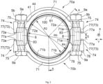
FIG. 2] FIG. 2 is a view showing a state before a retaining ring is tightened, as seen in a pipe-axis direction. - [
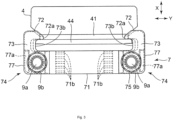
FIG. 3] FIG. 3 is a plan view ofFIG. 2 . - [
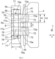
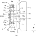
FIG. 4] FIG. 4 is a side view ofFIG. 2 . - [
FIG. 5] FIG. 5 is an A-A sectional view ofFIG. 2 . - [
FIG. 6] FIG. 6 is a view illustrating a latched state between a retaining ring and a pressing ring before pipe insertion. - [
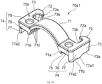
FIG. 7] FIG. 7 is a perspective view showing a first divisional component. - [
FIG. 8] FIG. 8 is a perspective view showing a second divisional component. - [
FIG. 9] FIG. 9 is an enlarged plan view showing a part around a back surface of a flange portion of the first divisional component shown inFIG. 7 . - [
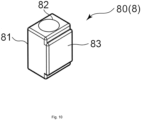
FIG. 10] FIG. 10 is a perspective view showing a rubber member. - [
FIG. 11] FIG. 11 is a view corresponding toFIG. 2 and showing a state after the retaining ring is tightened. - [
FIG. 12] FIG. 12 is a view corresponding toFIG. 4 and showing a state after the retaining ring is tightened. - [
FIG. 13] FIG. 13 is a perspective view showing a first divisional component in another embodiment of the present invention. - [
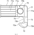
FIG. 14] FIG. 14 is an enlarged plan view showing a part around a back surface of a flange portion of the first divisional component shown inFIG. 13 . - [
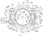
FIG. 15] FIG. 15 is a view corresponding toFIG. 2 , in the other embodiment of the present invention. - [
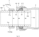
FIG. 16] FIG. 16 is a view corresponding toFIG. 5 , in the other embodiment of the present invention. - [
FIG. 17] FIG. 17 is a view corresponding toFIG. 11 , in the other embodiment of the present invention. - [
FIG. 18] FIG. 18 is a view corresponding toFIG. 12 , in the other embodiment of the present invention. - [
FIG. 19] FIG. 19 is a perspective view showing a first divisional component in still another embodiment of the present invention. - [
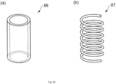
FIG. 20] FIG. 20 is a view showing a modification of a compressively-deformable held member. - Next, with reference to
FIGS. 1 to 12 as necessary, a first embodiment of the present invention will be described more specifically. - As shown in
FIGS. 1 and5 , a pipedetachment preventing device 1 for a union nut pipe fitting 10 according to the present invention roughly includes afitting body 2 into which anon-threaded pipe 100 is inserted, aunion nut 4 screwed and tightened to a receivingportion 21 with an annular rubber packing 3 interposed therebetween, and a retainingring 7 composed of a pair of first and seconddivisional components peripheral surface 101 of apipe 100 by tighteningmeans 9 so as to be opposed to each other. - In the present embodiment, as shown in
FIG. 5 , thepipe 100 is an inner-surface-lined steel pipe with a lining 103 coating an inner-peripheral surface 102 of thepipe 100, and the outer-peripheral surface 101 is not coated with a lining. Examples of the material of the lining 103 include rigid polyvinyl chloride and polyethylene. When thepipe 100 is cut, ametal pipe body 111 is exposed at the cut surface (pipe-end surface 112), and corrosion progresses from an exposedportion 113 of the pipe-end surface 112 and the outer-peripheral surface 101 which are exposed metal parts. Accordingly, in the present embodiment, a corrosion-prevention core 5 and arubber cover 6 are attached to a pipe-end portion 110, so as to cover the outer-peripheral surface 101 and the pipe-end surface 112 inside thefitting body 2, thereby preventing corrosion of the pipe-end portion 110. - As shown in
FIGS. 1 and5 , thefitting body 2 has the tapered receivingportion 21 and anexternal thread 22 formed on an outer-peripheral surface thereof. An inner diameter R1 of the receivingportion 21 is slightly greater than the sum of an outer diameter R2 of thepipe 100 and a thickness t1 of therubber cover 6 so that the pipe-end portion 110 with therubber cover 6 attached thereto can be inserted. - In the present embodiment, as shown in
FIGS. 1 and5 , theunion nut 4 has agroove 41 which is provided on an outer-peripheral surface and to which hooks 72 of the retainingring 7 are latched, aninternal thread 42 formed on an inner-peripheral surface, and anannular flange 44 protruding from thegroove 41. By screwing and tightening theunion nut 4 to the receivingportion 21, thepacking 3 is compressively deformed to ensure a waterproof state for the pipe fitting. An inner diameter R3 of anopening 43 of theunion nut 4 is also slightly greater than the sum of the outer diameter R2 of thepipe 100 and the thickness t1 of therubber cover 6 so that the pipe-end portion 110 with therubber cover 6 attached thereto can be inserted. - As shown in
FIG. 5 , the corrosion-prevention core 5 has atubular portion 51 covering the lining 103 on the inner-peripheral surface 102 of the pipe-end portion 110, and anannular brim 52 protruding outward from thetubular portion 51. A plurality ofannular projections 53 are provided on the inner side of thetubular portion 51. Thetubular portion 51 has an outer diameter slightly greater than the inner diameter of thepipe 100, so as to closely contact with the lining 103 on the inner-peripheral surface 102 of thepipe 100. As such a corrosion-prevention core 5, for example, a product as described inJapanese Laid-Open Patent Publication No. 2009-41638 - As shown in
FIG. 5 , therubber cover 6 has atubular portion 61 closely contacting with the outer-peripheral surface 101 of the pipe-end portion 110, and anannular rib 62 protruding from thetubular portion 61 toward the center. The thickness t1 of rubber of thetubular portion 61 is, for example, approximately equal to a thickness of an outer-surface coating of an inner-and-outer-surface-lined steel pipe, and is 1.0 to 1.5 mm, for example. In addition, the extension/contraction amount in an axial direction X of thetubular portion 61 is not greater than 1.0 mm, for example, A protrusion width W of therib 62 is smaller than a thickness t2 of thepipe body 111, and aninner end 62a of therib 62 is located on the outer-peripheral surface 101 side relative to an inner edge (inner-peripheral surface 102 side) of the pipe-end surface 112. - As shown in
FIGS. 2 to 4 ,6 ,7 , and9 , the firstdivisional component 70a of the retainingring 7 has abody portion 71 along the outer-peripheral surface 101,arms 73 which are along the axial direction X of thepipe 100 and are provided with, at distal ends, thehooks 72 to be latched to theunion nut 4, and protrudingportions 74 provided with thearms 73 and protruding outward fromend portions 71a of thebody portion 71. The firstdivisional component 70a is left-right symmetric with respect to the center of thebody portion 71. - On the back surface (
pipe 100 side) of thebody portion 71,teeth 71b protruding toward thepipe 100 side are provided near the protrudingportions 74. A plurality of theteeth 71b are arranged at appropriate intervals in the width direction (the axial direction X of the pipe 100) of thebody portion 71. In addition, theteeth 71b are provided line-symmetrically with respect to the center of thebody portion 71. - Each protruding
portion 74 has aflange portion 75 having a throughhole 76 through which abolt 9a of the tightening means 9 penetrates, and awall portion 77 extending from theflange portion 75. In the present embodiment, thewall portion 77 is provided only at a side part (a radially outer end of the pipe 100) along the axial direction X of theflange portion 75. Then, as shown inFIG. 9 , the back surface of theflange portion 75 is aflat surface 75b, and members corresponding to thewall portion 77 are not provided at both ends orthogonal to the axial direction X of theflat surface 75b of theflange portion 75. It is noted that, as shown inFIG. 4 , a length L along the axial direction X of thewall portion 77 is equivalent to a length along the axial direction X of a compressively-deformable held member 8 (rubber member 80). - Here, as shown in
FIG. 4 , thehook 72 and thearm 73 are formed with the same height (thickness) H1 from atop surface 75a of theflange portion 75. Meanwhile, thewall portion 77 is formed with a height (thickness) H2 from thetop surface 75a of theflange portion 75. That is, anend portion 77a of thewall portion 77 opposed to the other divisional component slightly protrudes toward the other divisional component relative to anend portion 73a of thearm 73 and thehook 72 opposed to the other divisional component (H1 < H2). - As shown in
FIGS. 2 to 4 ,6 , and8 , the seconddivisional component 70b of the retainingring 7 has the same configuration as the firstdivisional component 70a. However, the seconddivisional component 70b is different from the firstdivisional component 70a in thatridges 78 for preventing rotation of the head of thebolt 9a are provided on thetop surface 75a of eachflange portion 75. - In addition, the retaining
ring 7 has the compressively-deformable heldmembers 8 through which the tightening means 9 are inserted and which are held between theflange portions 75 opposed to each other. In the present embodiment, as the compressively-deformable heldmembers 8, the compressively-deformable rubber members 80 are used. As shown inFIG. 10 , eachrubber member 80 has abody portion 81 having a substantially rectangular shape, and a throughhole 82 which penetrates through thebody portion 81 and through which thebolt 9a of the tightening means 9 penetrates. Thebody portion 81 has a heldportion 83 which protrudes outward from one side surface and is held between theend portions 71a of thebody portions 71 opposed to each other. - Here, temporary assembling and installation of the pipe
detachment preventing device 1 will be described. - First, the first and second
divisional components rubber members 8 are placed between theflange portions 75 of thedivisional components portion 83 of eachrubber member 80 is held between theend portions 71a of thebody portions 71. Further, the width of thebody portion 81 is equivalent to the interval between thewall portion 77 and theend portion 71a of thebody portion 71, and thebody portion 81 contacts with theflat surface 75b of theflange portion 75 and is held between theend portion 71a and thewall portion 77. Thus, at the time of inserting thebolt 9a, the posture of therubber member 8 can be stably kept between theflange portions 75 opposed to each other, whereby insertion of thebolt 9a is facilitated and workability improves. - Then, the
arms 72 of the first and seconddivisional components groove 41 of theunion nut 4, thebolts 9a are inserted into the throughholes 76 of theflange portions 75 and the throughholes 82 of therubber members 80, and nuts 9b are screwed to thebolts 9a. Thus, the retainingring 7 is latched to theunion nut 4 in a loose-fit state, so that the pipedetachment preventing device 1 comes into a temporarily-assembled state. By interposing therubber members 80 between theflange portions 75 of the first and seconddivisional components nut 9b comes off and the temporarily-assembled state of the pipedetachment preventing device 1 is released. - In the loose-fit state (temporarily-assembled state), each
rubber member 80 is slightly compressed by theflange portions 75 with thenut 9b tightened. In addition, as shown inFIGS. 4 and6 , a gap S is formed by therubber member 80, between thewall portions 77 of the first and seconddivisional components rubber member 80, the first and seconddivisional components pipe 100 into thefitting body 2, the first and seconddivisional components pipe 100, a worker need not hold the first and seconddivisional components detachment preventing device 1, the inner diameter of the retainingring 7 is kept greater than the outer diameter of thepipe 100 by therubber members 80, whereby insertion of thepipe 100 is facilitated. - Further, as shown in
FIG. 6 , in a state before thepipe 100 is inserted, the first and seconddivisional components rubber cover 61 is attached to the outer-peripheral surface 101 of thepipe 100 to be inserted, theteeth 71b and the outer-peripheral surface 101 are separated from each other. Therefore, if the height (thickness) H1 of thehook 72 and thearm 73 is low (thin), the retainingring 7 might come off theunion nut 4. Accordingly, for example, the height (thickness) H1 of thehook 72 and thearm 73 is set to be greater than a thickness T of the flange portion 75 (T < H1 < H2). Thus, adistal end 72a of thehook 72 of the firstdivisional component 70a forms an interference portion Pi1 (hatched part inFIG. 6 ) that can interfere (contact) with theannular flange 44, and a part of adistal end 72a of thehook 72 of the seconddivisional component 70b also forms an interference portion Pi2 (hatched part inFIG. 6 ) that can interfere with theannular flange 44, whereby the retainingring 7 can be prevented from coming off. - Then, the
bolts 9a and the nuts 9b are tightened, whereby the retainingring 7 is tightened and fixed to thepipe 100. At this time, thebolts 9a and the nuts 9b are tightened until the gaps S formed between thewall portions 77 disappear. As shown inFIGS. 11 and12 , thebolts 9a and the nuts 9b only have to be tightened until the distal ends 77a of thewall portions 77 come into contact with each other. Thus, completion of tightening work can be easily confirmed and variations in the tightening amount among workers can be reduced. Moreover, since theend portion 77a of the firstdivisional component 70a protrudes toward the seconddivisional component 70b relative to theend portion 73a of thearm 73 and thehook 72 of the firstdivisional component 70a (H1 < H2), theend portions 73a of thearms 73 and thehooks 72 opposed to each other do not contact with each other when tightening work is completed. - In addition, when the tightening means 9 are tightened, as shown in
FIG. 11 , a center part of eachbody portion 71 is deformed so as to come close to thepipe 100 and theteeth 71b bite into thepipe 100. Thus, detachment of thepipe 100 is prevented. Here, eachwall portion 77 is provided only at the side part (the radially outer end of the pipe 100) along the axial direction X of theflange portion 75. Thus, as shown inFIG. 12 , therubber member 80 is compressively deformed by theflange portions 75, and the compressive deformation is led in the axial direction X where thewall portions 77 are absent. Since two locations on both sides (front and rear sides) in the axial direction X of theflange portions 75 are opened, tightening torque does not become excessive and workability is not lowered. In addition, since a part of the compressivelydeformed body portion 81 protrudes out in the axial direction X from theflange portions 75 as shown inFIG. 12 , thebody portion 81 protruding out from theflange portions 75 can be visually recognized as seen in the axial direction of thebolt 9a in tightening work, whereby the tightening degree can be easily confirmed. Moreover, since therubber member 80 is an elastically-deformable member, when thenut 9b is loosened, the restoration force of therubber member 80 acts so as to separate the first and seconddivisional components pipe 100 can be easily detached from the retainingring 7. Thus, the pipedetachment preventing device 1 according to the present embodiment using therubber member 80 is suitable also for re-installation. - Next, with reference to
FIGS. 13 to 18 , a second embodiment of the present invention will be described. In the following embodiment, members and the like similar to those in the above first embodiment are denoted by the same reference characters. - In the above first embodiment, the case where the
pipe 100 is an inner-surface-lined steel pipe and has the corrosion-prevention core 5 and therubber cover 6 attached to the pipe-end portion 110 has been described as an example. However, thepipe 100 is not limited to an inner-surface-lined steel pipe and may be an inner-and-outer-surface-coated pipe. Further, thepipe 100 is not limited to a steel pipe and may be a plastic pipe 100' such as a polyethylene pipe or a polyvinyl chloride pipe. In such a case, as shown inFIG. 16 , the pipe 100' is not coated on the inner and outer surfaces, and the corrosion-prevention core 5 and therubber cover 6 are not needed. - Since such a plastic pipe 100' has elasticity and flexibility, in order to prevent detachment of the pipe 100', a
body portion 71 of each of first and seconddivisional components arc teeth 71c along the circumferential direction over the entire back surface, as shown inFIGS. 13 to 15 . The diameter of the retainingring 7 is slightly reduced relative to the outer diameter of the pipe 100' so that thearc teeth 71c bite into the pipe 100', thereby improving a pipe detachment preventing force. - Also in the present embodiment, the retaining
ring 7 has therubber members 80 through which the tightening means 9 are inserted and which are held between theflange portions 75 opposed to each other. Then, in a temporarily-assembled state (loose-fit state) of the pipedetachment preventing device 1, eachrubber member 80 is slightly compressed by theflange portions 75 opposed to each other. In addition, as shown inFIG. 15 , a gap S is formed by therubber member 80, between theend portions 77a of thewall portions 77 of the first and seconddivisional components divisional components divisional component 70d is different from the firstdivisional component 70c in that theridges 78 are provided on thetop surface 75a of eachflange portion 75 but the other configurations are the same. - In addition, the configurations of the protruding portions 74 (
flange portions 75, throughholes 76, and wall portions 77) are the same as those in the above first embodiment. Eachwall portion 77 is provided only at the side part (the radially outer end of the pipe 100) along the axial direction X of theflange portion 75. Thus, as shown inFIG. 18 , compressive deformation of therubber member 80 by diameter reduction of the retainingring 7 is led to two locations on both sides (front and rear sides) in the axial direction X of theflange portions 75 where thewall portions 77 are not provided. Therefore, tightening torque does not become excessive and workability is not lowered. - Here, as shown in
FIGS. 15 and18 , a height (height/thickness from thetop surface 75a of the flange portion 75) H3 of thehook 72 is greater than a height (height/thickness from thetop surface 75a of the flange portion 75) H4 of the arm 73 (H4 < H3). In addition, the height H4 of thearm 73 is approximately equal to the thickness T of theflange portion 75. Then, the height (height/thickness from thetop surface 75a of the flange portion 75) H2 of thewall portion 77 is greater than the height H3 of thehook 72. That is, theend portion 77a of thewall portion 77 opposed to the other divisional component protrudes toward the other divisional component relative to anend portion 72b of thehook 72 opposed to the other divisional component (H4 < H3 < H2). Further, the height H3 of thehook 72 is greater than the thickness T of the flange portion 75 (T < H3 < H2). Thus, even if the first and seconddivisional components hooks 72 interfere (contact) with theannular flange 44, whereby the retainingring 7 is prevented from coming off. - In addition, also in the present embodiment, the
bolts 9a and the nuts 9b are tightened until the gaps S formed between thewall portions 77 disappear, whereby the retainingring 7 is tightened and fixed to the pipe 100'. As shown inFIG. 17 , the diameter of the pipe 100' is reduced by thebody portions 71 of the first and seconddivisional components arc teeth 71c bite into the pipe 100'. Thus, detachment of the pipe 100' is prevented. At this time, as shown inFIG. 18 , thebolts 9a and the nuts 9b only have to be tightened until the distal ends 77a of thewall portions 77 come into contact with each other. Thus, completion of tightening work can be easily confirmed and variations in the tightening amount among workers can be reduced. Moreover, since theend portion 77a of the firstdivisional component 70c protrudes toward the seconddivisional component 70d relative to theend portion 72b of thehook 72 of the firstdivisional component 70a (H4 < H3), theend portions 72b of thehooks 72 opposed to each other do not contact with each other when tightening work is completed. - Finally, other possible embodiments will be described.
- In the above embodiments, a distal-end surface of the
end portion 77a of thewall portion 77 is formed to be a flat surface. However, the shape of theend portion 77a is not limited thereto. For example, as shown inFIG. 17 , thewall portion 77 may have arecess 77b, to form paired end portions 77a1, 77a2. It suffices that tightening work can be managed using contact between theend portions 77a of thewall portions 77 and the end portions of thehooks 72 do not contact with each other. - In the above embodiments, the through
hole 82 of therubber member 80 has a circular shape in a plan view, but may have any shape as long as thebolt 9a can penetrate (be inserted) therethrough. For example, the shape of the throughhole 82 may be a U shape in a plan shape. However, in a case of a U shape, both end portions of the U shape expand through compressive deformation so that therubber member 80 might come off theflange portions 75. Therefore, as shown in the above embodiments, the throughhole 82 having a circular shape is preferable. - In the above embodiments, as the compressively-deformable held
member 8, the elastically-deformable rubber member 80 is used. However, the heldmember 8 is not limited thereto, and for example, atubular member 86 made of a plastically-deformable material as shown inFIG. 20(a) may be used. Thetubular member 86 is, for example, a cylindrical nylon tube, and provides effects equivalent to those in the above embodiments. However, since thetubular member 86 is plastically deformable, therubber member 80 is more suitable for reinstallment. It is noted that examples of the plastically-deformable material include polyurethane and polyolefin, as well as nylon, but any material may be used as long as the material is plastically deformable to such an extent that does not hamper tightening by the tightening means 9. - Further, instead of the
rubber member 80, ahelical compression spring 87 as shown inFIG. 20(b) may be used. Thehelical compression spring 87 is also an elastically-deformable member and therefore provides effects equivalent to those of therubber member 80. - It is noted that, as shown in
FIGS. 9 and14 , in a case where the interval between thewall portion 77 and theend portion 71a of thebody portion 71 is shorter than the length along the axial direction X of theflat surface 75b on the back side of the flange portion 75 (theflat surface 75b is not square), thecylindrical member 86 can be attached in a state deformed in a substantially elliptic shape. In addition, each of thecylindrical member 86 and thehelical compression spring 87 may be formed in a substantially elliptic shape as seen in the axial direction (in a plan view) in accordance with the shape of theflat surface 75b. - In addition, in the above embodiments, since the tightening direction (the axial direction of the
bolt 9a) of the tightening means 9 substantially coincides with the vertical direction, the heldmember 8 can be stably held between theflat surfaces 75b of theflange portions 75 opposed to each other. However, for example, in a case where the tightening direction of the tightening means 9 substantially coincides with the horizontal direction, if each of thecylindrical member 86 and thehelical compression spring 87 is formed in a substantially elliptic shape as described above, the posture of the heldmember 8 is kept by contact with thewall portion 77 or theend portion 71a of thebody portion 71, whereby insertion of thebolt 9a is facilitated. - As described above, for the compressively-deformable held
member 8, either an elastically-deformable material or a plastically-deformable material can be used as long as the material is deformable to such an extent that does not hamper tightening by the tightening means 9. In addition, the plan-view shape of the compressively-deformable heldmember 8 is not limited to a circular shape or an elliptic shape. -
- 1
- pipe detachment preventing device
- 2
- fitting body
- 3
- packing
- 4
- union nut
- 5
- corrosion-prevention core
- 6
- rubber cover
- 7
- retaining ring
- 8
- compressively-deformable held member
- 9
- tightening means
- 9a
- bolt
- 9b
- nut
- 10
- union nut pipe fitting
- 21
- receiving portion
- 22
- external thread
- 41
- groove
- 42
- internal thread
- 43
- opening
- 44
- annular flange
- 51
- tubular portion
- 52
- brim
- 53
- annular projection
- 61
- tubular portion
- 61a
- end portion
- 61b
- distal end
- 62
- rib
- 62a
- inner end
- 63
- opening
- 70a, 70c
- first divisional component
- 70b, 70d
- second divisional component
- 71
- body portion
- 71a
- end portion
- 71b
- tooth
- 71c
- arc tooth
- 72
- hook
- 72a
- distal end
- 72b
- end portion
- 73
- arm
- 73a
- end portion
- 73b
- inner surface
- 74
- protruding portion
- 75
- flange portion
- 75a
- top surface
- 75b
- flat surface (back surface)
- 76
- through hole
- 77
- wall portion
- 77a, 77a1, 77a2
- end portion
- 78
- ridge
- 80
- rubber member
- 81
- body portion
- 82
- through hole
- 83
- held portion
- 86
- cylindrical member
- 87
- helical compression spring
- 100
- pipe (inner-surface-lined steel pipe)
- 100'
- pipe (plastic pipe)
- 101
- outer-peripheral surface
- 102
- inner-peripheral surface
- 103
- lining
- 110
- pipe-end portion
- 1 1 1
- pipe body
- 112
- pipe-end surface
- 113
- exposed portion
- C
- cut portion
- H1
- height (thickness) of hook and arm
- H2
- height (thickness) of wall portion
- H3
- height of hook
- H4
- height of arm
- R1
- inner diameter of receiving portion
- R2
- outer diameter of pipe
- R3
- inner diameter of opening
- R4
- inner diameter of tooth tip
- R5
- outer diameter of rubber cover
- T
- thickness of flange portion
- t1
- thickness of tubular portion
- t2
- thickness of pipe body
- S
- gap
- Pi1, Pi2
- interference portion
- X
- axial direction
- Y
- orthogonal direction
- W
- protrusion width
Claims (12)
- A pipe detachment preventing device for a union nut pipe fitting, comprising:a fitting body having a receiving portion which has an external thread on an outer surface thereof and into which a non-threaded pipe is inserted;a union nut which is screwed and tightened to the receiving portion with an annular rubber packing interposed therebetween; anda retaining ring composed of a pair of divisional components fixed to an outer-peripheral surface of the pipe by tightening means so as to be opposed to each other, whereineach divisional component includesa body portion along the outer-peripheral surface,an arm which is along an axial direction of the pipe and is provided with, at a distal end, a hook to be latched to the union nut, anda protruding portion provided with the arm and protruding outward from an end portion of the body portion,the protruding portion has at least a flange portion having a through hole through which the tightening means penetrates, and a wall portion extending from the flange portion,an end portion of the wall portion opposed to another divisional component is formed so as to protrude toward the other divisional component relative to end portions of the arm and the hook opposed to the other divisional component,the retaining ring has a compressively-deformable held member through which the tightening means is inserted and which is held between the flange portions opposed to each other,the held member forms a gap between the end portions of the wall portions when the pair of divisional components are coupled by the tightening means and latched to the union nut in a loose-fit state, andthe tightening means is tightened until the end portions of the wall portions come into contact with each other, thus tightening and fixing the pair of divisional components to the outer-peripheral surface of the pipe.
- The pipe detachment preventing device for a union nut pipe fitting according to claim 1, wherein
the wall portion is provided only at a side part along the axial direction of the flange. - The pipe detachment preventing device for a union nut pipe fitting according to claim 1 or 2, wherein
a height of the hook from a top surface of the flange portion is greater than a thickness of the flange portion. - The pipe detachment preventing device for a union nut pipe fitting according to claim 3, wherein
a height of the arm from the top surface of the flange portion is equal to or smaller than the height of the hook from the top surface of the flange portion. - The pipe detachment preventing device for a union nut pipe fitting according to any one of claims 1 to 4, wherein
the held member is a rubber member. - The pipe detachment preventing device for a union nut pipe fitting according to claim 5, wherein
the rubber member has a body portion with a substantially rectangular shape, and a held portion which protrudes outward from one side surface of the body portion and is held between the end portions of the body portions of the divisional components opposed to each other. - The pipe detachment preventing device for a union nut pipe fitting according to claim 6, wherein
the body portion of the rubber member is held between the wall portion and the end portion of the body portion of each divisional component. - The pipe detachment preventing device for a union nut pipe fitting according to any one of claims 5 to 7, wherein
the rubber member has a through hole through which the tightening means penetrates and which has a circular shape in a plan view. - The pipe detachment preventing device for a union nut pipe fitting according to claim 1, wherein
the held member is a tubular member made of a plastically-deformable material. - The pipe detachment preventing device for a union nut pipe fitting according to claim 1, wherein
the held member is a helical compression spring. - The pipe detachment preventing device for a union nut pipe fitting according to any one of claims 1 to 9, wherein
the pipe is an inner-surface-lined steel pipe or an inner-and-outer-surface-lined steel pipe, and on an inner surface of the body portion, a tooth is formed near the protruding portion. - The pipe detachment preventing device for a union nut pipe fitting according to any one of claims 1 to 10, wherein
the pipe is a plastic pipe, and on an inner surface of the body portion, a plurality of teeth are formed along a circumferential direction of the pipe.
Applications Claiming Priority (2)
| Application Number | Priority Date | Filing Date | Title |
|---|---|---|---|
| JP2021095479 | 2021-06-07 | ||
| PCT/JP2021/048258 WO2022259583A1 (en) | 2021-06-07 | 2021-12-24 | Pipe detachment preventing device for union nut pipe fitting |
Publications (4)
| Publication Number | Publication Date |
|---|---|
| EP4354004A1 true EP4354004A1 (en) | 2024-04-17 |
| EP4354004A4 EP4354004A4 (en) | 2024-12-18 |
| EP4354004B1 EP4354004B1 (en) | 2026-02-04 |
| EP4354004C0 EP4354004C0 (en) | 2026-02-04 |
Family
ID=84425636
Family Applications (1)
| Application Number | Title | Priority Date | Filing Date |
|---|---|---|---|
| EP21944447.8A Active EP4354004B1 (en) | 2021-06-07 | 2021-12-24 | Pipe detachment preventing device for union nut pipe fitting |
Country Status (5)
| Country | Link |
|---|---|
| US (1) | US12535159B2 (en) |
| EP (1) | EP4354004B1 (en) |
| JP (1) | JP7283837B2 (en) |
| TW (1) | TWI831232B (en) |
| WO (1) | WO2022259583A1 (en) |
Families Citing this family (1)
| Publication number | Priority date | Publication date | Assignee | Title |
|---|---|---|---|---|
| EP4729820A1 (en) * | 2024-10-17 | 2026-04-22 | Mettler-Toledo (Albstadt) GmbH | Kit of parts for releasably coupling and securing a tubular element to a fitting, fitting system comprising the kit of parts, and methods for assembling and disassembling assemblies comprising the fitting system |
Family Cites Families (13)
| Publication number | Priority date | Publication date | Assignee | Title |
|---|---|---|---|---|
| JPS585585A (en) | 1981-06-30 | 1983-01-12 | 株式会社川西水道機器製作所 | Pipe joint |
| US4966395A (en) * | 1989-08-11 | 1990-10-30 | Quikcoup, Incorporated | Rigid or flexible coupling for pipes |
| US5490693A (en) * | 1994-09-28 | 1996-02-13 | Cajon Company | Tube coupling locking device |
| JP3918099B2 (en) * | 2003-12-10 | 2007-05-23 | 株式会社川西水道機器 | Pipe detachment prevention device for union nut joint and disassembly method |
| JP3858227B2 (en) * | 2004-02-26 | 2006-12-13 | 株式会社川西水道機器 | Pipe detachment prevention device for union nut joint |
| US7086131B2 (en) | 2004-05-14 | 2006-08-08 | Victaulic Company | Deformable mechanical pipe coupling |
| JP4925965B2 (en) | 2007-08-08 | 2012-05-09 | 株式会社川西水道機器 | Pipe end anticorrosion core |
| ITTO20090134U1 (en) * | 2009-09-21 | 2009-12-21 | Paolo Artini | RTAU SAFETY COLLAPSE AND ANTI-SCREWING SAFETY COLLAR |
| JP5456092B2 (en) | 2012-03-29 | 2014-03-26 | 株式会社川西水道機器 | Pipe detachment prevention device for union nut joint |
| GB2514556B (en) * | 2013-05-28 | 2020-05-06 | Onesubsea Ip Uk Ltd | Locking device |
| DE102014102356A1 (en) | 2014-02-24 | 2015-08-27 | Norma Germany Gmbh | profile clip |
| KR101916699B1 (en) * | 2016-06-16 | 2018-11-09 | 주식회사 에스와이락코리아 | Clamp unit for fluid pipeline connection |
| KR101754397B1 (en) | 2016-07-14 | 2017-07-06 | 남상건 | Grooveless coupling |
-
2021
- 2021-12-24 WO PCT/JP2021/048258 patent/WO2022259583A1/en not_active Ceased
- 2021-12-24 EP EP21944447.8A patent/EP4354004B1/en active Active
- 2021-12-24 US US18/566,050 patent/US12535159B2/en active Active
- 2021-12-24 JP JP2022573565A patent/JP7283837B2/en active Active
-
2022
- 2022-06-02 TW TW111120683A patent/TWI831232B/en active
Also Published As
| Publication number | Publication date |
|---|---|
| US12535159B2 (en) | 2026-01-27 |
| EP4354004B1 (en) | 2026-02-04 |
| JP7283837B2 (en) | 2023-05-30 |
| EP4354004C0 (en) | 2026-02-04 |
| US20240247740A1 (en) | 2024-07-25 |
| TWI831232B (en) | 2024-02-01 |
| WO2022259583A1 (en) | 2022-12-15 |
| JPWO2022259583A1 (en) | 2022-12-15 |
| EP4354004A4 (en) | 2024-12-18 |
| CA3220625A1 (en) | 2022-12-15 |
| TW202248558A (en) | 2022-12-16 |
Similar Documents
| Publication | Publication Date | Title |
|---|---|---|
| US7240925B2 (en) | Tube joint | |
| KR101585909B1 (en) | Pipe joint | |
| EP3517792A1 (en) | Compression limiting fastening system | |
| CN105745458A (en) | Riveting collar and self-locking nut | |
| KR102212313B1 (en) | Profile clamp having sealing element | |
| CN115523056A (en) | Solid rocket engine connected by clamping ring | |
| US12486927B2 (en) | Press-fitting connection structure for pipeline and refrigeration device | |
| EP4354004B1 (en) | Pipe detachment preventing device for union nut pipe fitting | |
| JP3206782B2 (en) | Plug-in fittings | |
| CA3220625C (en) | Pipe detachment preventing device for union nut pipe fitting | |
| TW202246626A (en) | Anchor bolt | |
| JP2020120568A (en) | Cable gland | |
| JP5592751B2 (en) | Separation prevention device for pipe joint and push ring used therefor | |
| JPH058392Y2 (en) | ||
| JP3553290B2 (en) | Cap for preventing falling off and female screw member for preventing falling off including the cap | |
| JP2025101673A (en) | Corrosion-proof structure of pipe ends in union nut pipe fittings | |
| JP2022181136A (en) | Pipe end anti-corrosion structure in pipe joint | |
| JPH07280152A (en) | Pipe separation prevention fitting for union nut fitting | |
| JPH10141557A (en) | Pipe connection device | |
| JP3163375B2 (en) | Flexible fittings | |
| JP3700153B2 (en) | Press member for fluid pipe connection | |
| JP3570907B2 (en) | Jig for pipe joining | |
| EP0558013A2 (en) | Fixing structure for a member to be fixed | |
| JPH1082411A (en) | Drop-off prevention aid and drop-off prevention external thread member including the same | |
| JP5461911B2 (en) | Connecting band and pipe plug unit |
Legal Events
| Date | Code | Title | Description |
|---|---|---|---|
| STAA | Information on the status of an ep patent application or granted ep patent |
Free format text: STATUS: THE INTERNATIONAL PUBLICATION HAS BEEN MADE |
|
| PUAI | Public reference made under article 153(3) epc to a published international application that has entered the european phase |
Free format text: ORIGINAL CODE: 0009012 |
|
| STAA | Information on the status of an ep patent application or granted ep patent |
Free format text: STATUS: REQUEST FOR EXAMINATION WAS MADE |
|
| 17P | Request for examination filed |
Effective date: 20231123 |
|
| AK | Designated contracting states |
Kind code of ref document: A1 Designated state(s): AL AT BE BG CH CY CZ DE DK EE ES FI FR GB GR HR HU IE IS IT LI LT LU LV MC MK MT NL NO PL PT RO RS SE SI SK SM TR |
|
| DAV | Request for validation of the european patent (deleted) | ||
| DAX | Request for extension of the european patent (deleted) | ||
| A4 | Supplementary search report drawn up and despatched |
Effective date: 20241114 |
|
| RIC1 | Information provided on ipc code assigned before grant |
Ipc: F16L 27/12 20060101ALI20241108BHEP Ipc: F16L 21/08 20060101ALI20241108BHEP Ipc: F16L 19/03 20060101AFI20241108BHEP |
|
| STAA | Information on the status of an ep patent application or granted ep patent |
Free format text: STATUS: EXAMINATION IS IN PROGRESS |
|
| 17Q | First examination report despatched |
Effective date: 20250404 |
|
| GRAP | Despatch of communication of intention to grant a patent |
Free format text: ORIGINAL CODE: EPIDOSNIGR1 |
|
| STAA | Information on the status of an ep patent application or granted ep patent |
Free format text: STATUS: GRANT OF PATENT IS INTENDED |
|
| INTG | Intention to grant announced |
Effective date: 20250910 |
|
| GRAS | Grant fee paid |
Free format text: ORIGINAL CODE: EPIDOSNIGR3 |
|
| GRAA | (expected) grant |
Free format text: ORIGINAL CODE: 0009210 |
|
| STAA | Information on the status of an ep patent application or granted ep patent |
Free format text: STATUS: THE PATENT HAS BEEN GRANTED |
|
| AK | Designated contracting states |
Kind code of ref document: B1 Designated state(s): AL AT BE BG CH CY CZ DE DK EE ES FI FR GB GR HR HU IE IS IT LI LT LU LV MC MK MT NL NO PL PT RO RS SE SI SK SM TR |
|
| REG | Reference to a national code |
Ref country code: CH Ref legal event code: F10 Free format text: ST27 STATUS EVENT CODE: U-0-0-F10-F00 (AS PROVIDED BY THE NATIONAL OFFICE) Effective date: 20260204 Ref country code: GB Ref legal event code: FG4D |
|
| REG | Reference to a national code |
Ref country code: IE Ref legal event code: FG4D |
|
| REG | Reference to a national code |
Ref country code: DE Ref legal event code: R096 Ref document number: 602021047562 Country of ref document: DE |
|
| U01 | Request for unitary effect filed |
Effective date: 20260218 |
|
| U07 | Unitary effect registered |
Designated state(s): AT BE BG DE DK EE FI FR IT LT LU LV MT NL PT RO SE SI Effective date: 20260223 |
|
| PG25 | Lapsed in a contracting state [announced via postgrant information from national office to epo] |
Ref country code: RS Free format text: LAPSE BECAUSE OF FAILURE TO SUBMIT A TRANSLATION OF THE DESCRIPTION OR TO PAY THE FEE WITHIN THE PRESCRIBED TIME-LIMIT Effective date: 20260504 |
|
| PG25 | Lapsed in a contracting state [announced via postgrant information from national office to epo] |
Ref country code: ES Free format text: LAPSE BECAUSE OF FAILURE TO SUBMIT A TRANSLATION OF THE DESCRIPTION OR TO PAY THE FEE WITHIN THE PRESCRIBED TIME-LIMIT Effective date: 20260204 |
|
| PG25 | Lapsed in a contracting state [announced via postgrant information from national office to epo] |
Ref country code: PL Free format text: LAPSE BECAUSE OF FAILURE TO SUBMIT A TRANSLATION OF THE DESCRIPTION OR TO PAY THE FEE WITHIN THE PRESCRIBED TIME-LIMIT Effective date: 20260204 |
|
| PG25 | Lapsed in a contracting state [announced via postgrant information from national office to epo] |
Ref country code: GR Free format text: LAPSE BECAUSE OF FAILURE TO SUBMIT A TRANSLATION OF THE DESCRIPTION OR TO PAY THE FEE WITHIN THE PRESCRIBED TIME-LIMIT Effective date: 20260505 |
|
| PG25 | Lapsed in a contracting state [announced via postgrant information from national office to epo] |
Ref country code: NO Free format text: LAPSE BECAUSE OF FAILURE TO SUBMIT A TRANSLATION OF THE DESCRIPTION OR TO PAY THE FEE WITHIN THE PRESCRIBED TIME-LIMIT Effective date: 20260504 |
|
| PG25 | Lapsed in a contracting state [announced via postgrant information from national office to epo] |
Ref country code: HR Free format text: LAPSE BECAUSE OF FAILURE TO SUBMIT A TRANSLATION OF THE DESCRIPTION OR TO PAY THE FEE WITHIN THE PRESCRIBED TIME-LIMIT Effective date: 20260204 |
|
| PG25 | Lapsed in a contracting state [announced via postgrant information from national office to epo] |
Ref country code: IS Free format text: LAPSE BECAUSE OF FAILURE TO SUBMIT A TRANSLATION OF THE DESCRIPTION OR TO PAY THE FEE WITHIN THE PRESCRIBED TIME-LIMIT Effective date: 20260604 |