EP4353980A1 - Insert nut insertion structure - Google Patents
Insert nut insertion structure Download PDFInfo
- Publication number
- EP4353980A1 EP4353980A1 EP22828611.8A EP22828611A EP4353980A1 EP 4353980 A1 EP4353980 A1 EP 4353980A1 EP 22828611 A EP22828611 A EP 22828611A EP 4353980 A1 EP4353980 A1 EP 4353980A1
- Authority
- EP
- European Patent Office
- Prior art keywords
- insert nut
- flange portion
- fingers
- pair
- bolt fastening
- Prior art date
- Legal status (The legal status is an assumption and is not a legal conclusion. Google has not performed a legal analysis and makes no representation as to the accuracy of the status listed.)
- Granted
Links
Images






Classifications
-
- F—MECHANICAL ENGINEERING; LIGHTING; HEATING; WEAPONS; BLASTING
- F16—ENGINEERING ELEMENTS AND UNITS; GENERAL MEASURES FOR PRODUCING AND MAINTAINING EFFECTIVE FUNCTIONING OF MACHINES OR INSTALLATIONS; THERMAL INSULATION IN GENERAL
- F16B—DEVICES FOR FASTENING OR SECURING CONSTRUCTIONAL ELEMENTS OR MACHINE PARTS TOGETHER, e.g. NAILS, BOLTS, CIRCLIPS, CLAMPS, CLIPS OR WEDGES; JOINTS OR JOINTING
- F16B37/00—Nuts or like thread-engaging members
- F16B37/04—Devices for fastening nuts to surfaces, e.g. sheets, plates
- F16B37/041—Releasable devices
- F16B37/043—Releasable devices with snap action
-
- F—MECHANICAL ENGINEERING; LIGHTING; HEATING; WEAPONS; BLASTING
- F16—ENGINEERING ELEMENTS AND UNITS; GENERAL MEASURES FOR PRODUCING AND MAINTAINING EFFECTIVE FUNCTIONING OF MACHINES OR INSTALLATIONS; THERMAL INSULATION IN GENERAL
- F16B—DEVICES FOR FASTENING OR SECURING CONSTRUCTIONAL ELEMENTS OR MACHINE PARTS TOGETHER, e.g. NAILS, BOLTS, CIRCLIPS, CLAMPS, CLIPS OR WEDGES; JOINTS OR JOINTING
- F16B37/00—Nuts or like thread-engaging members
- F16B37/04—Devices for fastening nuts to surfaces, e.g. sheets, plates
- F16B37/045—Devices for fastening nuts to surfaces, e.g. sheets, plates specially adapted for fastening in channels, e.g. sliding bolts, channel nuts
-
- F—MECHANICAL ENGINEERING; LIGHTING; HEATING; WEAPONS; BLASTING
- F16—ENGINEERING ELEMENTS AND UNITS; GENERAL MEASURES FOR PRODUCING AND MAINTAINING EFFECTIVE FUNCTIONING OF MACHINES OR INSTALLATIONS; THERMAL INSULATION IN GENERAL
- F16B—DEVICES FOR FASTENING OR SECURING CONSTRUCTIONAL ELEMENTS OR MACHINE PARTS TOGETHER, e.g. NAILS, BOLTS, CIRCLIPS, CLAMPS, CLIPS OR WEDGES; JOINTS OR JOINTING
- F16B4/00—Shrinkage connections, e.g. assembled with the parts at different temperature; Force fits; Non-releasable friction-grip fastenings
- F16B4/004—Press fits, force fits, interference fits, i.e. fits without heat or chemical treatment
-
- F—MECHANICAL ENGINEERING; LIGHTING; HEATING; WEAPONS; BLASTING
- F16—ENGINEERING ELEMENTS AND UNITS; GENERAL MEASURES FOR PRODUCING AND MAINTAINING EFFECTIVE FUNCTIONING OF MACHINES OR INSTALLATIONS; THERMAL INSULATION IN GENERAL
- F16B—DEVICES FOR FASTENING OR SECURING CONSTRUCTIONAL ELEMENTS OR MACHINE PARTS TOGETHER, e.g. NAILS, BOLTS, CIRCLIPS, CLAMPS, CLIPS OR WEDGES; JOINTS OR JOINTING
- F16B7/00—Connections of rods or tubes, e.g. of non-circular section, mutually, including resilient connections
- F16B7/18—Connections of rods or tubes, e.g. of non-circular section, mutually, including resilient connections using screw-thread elements
- F16B7/187—Connections of rods or tubes, e.g. of non-circular section, mutually, including resilient connections using screw-thread elements with sliding nuts or other additional connecting members for joining profiles provided with grooves or channels
-
- H—ELECTRICITY
- H01—ELECTRIC ELEMENTS
- H01M—PROCESSES OR MEANS, e.g. BATTERIES, FOR THE DIRECT CONVERSION OF CHEMICAL ENERGY INTO ELECTRICAL ENERGY
- H01M50/00—Constructional details or processes of manufacture of the non-active parts of electrochemical cells other than fuel cells, e.g. hybrid cells
- H01M50/20—Mountings; Secondary casings or frames; Racks, modules or packs; Suspension devices; Shock absorbers; Transport or carrying devices; Holders
-
- Y—GENERAL TAGGING OF NEW TECHNOLOGICAL DEVELOPMENTS; GENERAL TAGGING OF CROSS-SECTIONAL TECHNOLOGIES SPANNING OVER SEVERAL SECTIONS OF THE IPC; TECHNICAL SUBJECTS COVERED BY FORMER USPC CROSS-REFERENCE ART COLLECTIONS [XRACs] AND DIGESTS
- Y02—TECHNOLOGIES OR APPLICATIONS FOR MITIGATION OR ADAPTATION AGAINST CLIMATE CHANGE
- Y02E—REDUCTION OF GREENHOUSE GAS [GHG] EMISSIONS, RELATED TO ENERGY GENERATION, TRANSMISSION OR DISTRIBUTION
- Y02E60/00—Enabling technologies; Technologies with a potential or indirect contribution to GHG emissions mitigation
- Y02E60/10—Energy storage using batteries
Definitions
- the present disclosure relates to an insert nut insertion structure for preventing deformation or damage of an injection molded structure by minimizing stress that may be applied to the injection molded structure when inserting an insert nut.
- Bolts and nuts are widely used to assemble two or more parts or structures. Keeping up with the recent trend towards reduced thickness of products, bolts or nuts are pre-installed in injection molded structures. For example, a body and a cover of a battery pack are made by forming a case that is divided into two and assembling the two cases, and to easily assemble the cases, an insert nut may be press fit or pre-installed by insert molding.
- Forming the injection molded part and the insert nut together by insert injection molding is advantageous in terms of assembly performance and durability, but when considering the factors such as the assembly structure of the product, the number of insert nuts required for the product and the manufacturing cost, it is better to form the injection molded part and press fitting the insert nut.
- the press fitting of the insert nut into the injection molded structure has a high likelihood of deformation or damage of the injection molded structure when press fitting the insert nut.
- the present disclosure is designed to solve the above-described problem, and therefore the present disclosure is directed to providing an insert nut insertion structure for preventing deformation or damage of an injection molded structure by minimizing stress that may be applied to the injection molded structure when inserting an insert nut.
- the present disclosure is further directed to providing an insert nut and an insert nut insertion structure for easily inserting the insert nut into an injection molded structure by hand without using a tool such as a hammer.
- an insert nut insertion structure of the present disclosure includes an insert nut including a bolt fastening portion having threads on an inner circumference into which a bolt is screwed; and a flange portion provided on an outer circumference of the bolt fastening portion and extended in a circumferential direction of the bolt fastening portion; and a nut fixing groove into which the insert nut is inserted in a first direction perpendicular to a direction in which the bolt is screwed, wherein the nut fixing groove includes a flange receiving portion having an internal space conforming to a shape of the flange portion; and a pair of fingers provided on the flange portion positioned in the flange receiving portion and formed in a cantilever shape that surrounds, in part, a periphery of the bolt fastening portion.
- the flange receiving portion may include a base plate on which the flange portion is seated; two side plates which are vertically extended from the base plate and contact two sides of the flange portion; and cover plates which are horizontally extended from the two side plates, contact an upper surface of the flange portion and are spaced a predetermined distance apart from the pair of fingers.
- the flange portion may be provided in contact with the cover plates and in non-contact with the pair of fingers.
- the flange portion may include a lower flange portion and an upper flange portion formed in double layer along a lengthwise direction of the bolt fastening portion, the upper flange portion may be positioned in a space between the pair of fingers and the cover plates, and the lower flange portion may be positioned in a space between the cover plates and the base plate.
- the lower flange portion may be provided in contact with the cover plates.
- the upper flange portion may be provided in non-contact with the pair of fingers.
- the bolt fastening portion may have a cylindrical shape, and the pair of fingers may be extended side by side in a contrary direction to the first direction with their facing inner surfaces being a curved surface conforming to the outer circumference of the bolt fastening portion.
- the pair of fingers may be made of an elastic material to allow the fingers to return to an original state when a force exerted to stretch the fingers wide apart is removed.
- a top periphery of the bolt fastening portion may be interference fit in between the pair of fingers in the first direction.
- a battery pack case including the insert nut insertion structure.
- FIG. 2 is a perspective view of an insert nut according to an embodiment of the present disclosure
- FIG. 3 is a perspective view showing the insert nut and a nut fixing groove according to an embodiment of the present disclosure
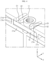
- FIG. 4 is a perspective view showing an assembly structure of the insert nut and the nut fixing groove of FIG. 3 .
- an insert nut insertion structure includes the insert nut 10 and the nut fixing groove 20.
- the insert nut 10 includes a bolt fastening portion 11 having threads 11a on the inner circumference into which a bolt 30 is screwed, and a flange portion 12 provided on the outer circumference of the bolt fastening portion 11 and extended in the circumferential direction of the bolt fastening portion 11.
- the nut fixing groove 20 may include a flange receiving portion 21 and a pair of fingers 22,23, and may be configured to allow the insert nut 10 to be inserted in a first direction (Y axis direction) perpendicular to the direction in which the bolt 30 is screwed.
- the present disclosure is configured to easily stretch the pair of fingers 22,23 wide apart with a small force, the fingers which play a role in holding the insert nut 10 when the insert nut 10 is inserted into the nut fixing groove 20, making it easy to insert the insert nut 10, and to apply a fastening force exerted by the bolt 30 to cover plates 21d,21e of the flange receiving portion 21 rather than the pair of fingers 22,23 when the bolt 30 is screwed, thereby reducing or eliminating deformation and damage risks of a case structure.
- the bolt fastening portion 11 of the insert nut 10 may have a cylindrical shape having threads on the inner circumference, and the flange portion 12 may have a rectangular plate shape and may be disposed on the bottom of the bolt fastening portion 11. Additionally, the insert nut 10 may include the cylindrical bolt fastening portion 11 protruding to a predetermined height in the Z axis direction from the center of the rectangular plate-shaped flange portion 12.
- the flange portion 12 has the horizontal length extended longer than the vertical length to cause the fastening force of the bolt 30 to act on the cover plates 21d,21e of the flange receiving portion 21 as described below when the bolt 30 is screwed into the insert nut 10 afterwards.
- the flange receiving portion 21 of the nut fixing groove 20 may have an internal space that conforms to the shape of the flange portion 12 to allow the insert nut 10 to be inserted, and as shown in FIG. 4 , the pair of fingers 22,23 may include the first finger 22 and the second finger 23 that are disposed on the flange portion 12, and each having a cantilever shape surrounding, in part, the periphery of the bolt fastening portion 11, when the flange portion 12 is placed in the flange receiving portion 21.
- the first finger 22 and the second finger 23 may be integrally formed with the upper plate of the case structure C1, and each extended side by side in a contrary direction (-Y axis direction) to the first direction (+Y axis direction), spaced such a distance apart from each other as to allow the bolt fastening portion 11 to be inserted, with their facing inner surfaces being a curved surface conforming to the outer circumference of the bolt fastening portion 11 to bring them into close contact with the outer circumference of the bolt fastening portion 11.
- the pair of fingers 22,23 may be in a cantilever shape at predetermined distances S1,S2 away from the cover plates 21d,21e and made of an elastic material so the first finger 22 and the second finger 23 can return to the original state after the force exerted to stretch wide apart is removed.
- the elastic material includes plastics that can return to the original state after it is a bit deformed with a small force.
- the pair of fingers 22,23 of this embodiment are integrally formed with the case structure C1 formed by plastic injection molding, but they are invulnerable to damage caused by the small force that is exerted to stretch the fingers 22,23 wide open, then removed.
- the pair of fingers 22,23 may be made of a metal to eliminate the damage risk of the pair of fingers 22,23.
- the pair of fingers 22,23 may be manufactured using a metal and assembled into the case structure C1.
- first finger 22 and the second finger 23 having the cantilever structure are easy to stretch wide apart, it is possible to insert the bolt fastening portion 11 in between the first finger 22 and the second finger 23 very easily when inserting the insert nut 10 into the nut fixing groove 20.
- the first finger 22 and the second finger 23 may be spontaneously stretched wide apart by the bolt fastening portion 11 when the flange portion 12 is pushed into the flange receiving portion 21 in the first direction without needing to stretch the first finger 22 and the second finger 23 wide apart by hand, and in this condition, when the flange portion 12 is completely pushed into the flange receiving portion 21, the first finger 22 and the second finger 23 may return to the original state and the top periphery of the bolt fastening portion 11 may be interference fitted in between the pair of fingers 22,23.
- the flange portion 12 of the insert nut 10 is disposed in the internal space of the flange receiving portion 21, and the upper part of the bolt fastening portion 11 is constrained between the first finger 22 and the second finger 23, thereby preventing the bolt fastening portion 11 from sliding away in the contrary direction (-Y axis direction) to the insertion direction.
- the flange receiving portion 21 of the nut fixing groove 20 may include a base plate 21a on which the flange portion 12 is seated, two side plates 21b,21c which are vertically extended from the base plate 21a and come into contact with the two sides of the flange portion 12, and the cover plates 21d,21e which are horizontally ( ⁇ X axis direction) extended from the two side plates 21b,21c, come into contact with the upper surface of the flange portion 12 and are spaced a predetermined distance apart from the pair of fingers 22,23.
- the insert nut 10 of this embodiment when the insert nut 10 of this embodiment is inserted into the nut fixing groove 20, the left side of the flange portion 12 contacts the left side plate 21b of the flange receiving portion 21, and the right side of the flange portion 12 contacts the right side plate 21c of the flange receiving portion 21. Accordingly, the insert nut 10 may be restrained from rotating when the bolt 30 is screwed afterwards.
- the upper surfaces of the horizontal ( ⁇ X axis direction) edges of the flange portion 12 are covered with the left cover plate 21d and the right cover plate 21e of the flange receiving portion 21. Accordingly, when the bolt 30 is screwed afterwards, the fastening force of the bolt 30 and the insert nut 10 is applied to the left cover plate 21d and the right cover plate 21e.
- the flange portion 12 is in contact with the cover plates 21d,21e and in non-contact with the pair of fingers 22,23 when the bolt 30 is screwed.
- the cover plates 21d,21e are thicker than the first finger 22 and the second finger 23.
- the base of the pair of fingers 22,23 is disposed at a higher position than the base of the cover plates 21d,21e.
- the case structure C1 having the insert nut insertion structure and another structure C2 may be assembled by the fastening of the bolt 30 and the insert nut 10.
- the insert nut 10 is held in place when the bolt 30 screws into the insert nut 10.
- the fastening force between the bolt 30 and the insert nut 10 is only applied to the left cover plate 21d and the right cover plate 21e as indicated by the arrow in FIG. 6 , and is not applied to the first finger 22 and the second finger 23. Accordingly, when the bolt 30 is screwed, the fastening force exerted by the bolt 30 hardly acts on the pair of fingers 22,23, so there is no deformation or damage risk of the pair of fingers 22,23.
- the insert nut insertion structure may insert the insert nut 10 into the nut fixing groove 20 easily and rapidly without needing to apply an excessive force or use a hammer to insert the insert nut into the groove of the structure as does the conventional press fitting, and has no or little risk of deformation or damage to the nut fixing groove 20 when inserting the insert nut 10 or installing the bolt 30.
- FIG. 7 is a perspective view of an insert nut 10A according to another embodiment of the present disclosure
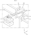
- FIG. 8 is a perspective view showing the insert nut 10A and a nut fixing groove 20A according to another embodiment of the present disclosure
- FIG. 9 is a perspective view showing an assembly structure of the insert nut 10A and the nut fixing groove 20A of FIG. 8
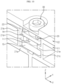
- FIG. 10 is a diagram showing an insert nut insertion structure and another structure fastened using a bolt 30 according to another embodiment of the present disclosure
- FIG. 11 is a schematic cross-sectional view of FIG. 10 .
- a bolt fastening portion 11 of the insert nut 10A has a cylindrical shape having threads on the inner circumference and a flange portion 13 has a rectangular plate shape.
- the flange portion 13 of the insert nut 10A of another embodiment of the present disclosure includes a lower flange portion 15 and an upper flange portion 14 in double layer along the lengthwise direction (Z axis direction) of the bolt fastening portion 11, the flange portion 13 has a shorter horizontal length, and the bolt fastening portion 11 is extended longer.
- the nut fixing groove 20A according to another embodiment of the present disclosure includes a flange receiving portion 21 and a pair of fingers 22,23 to allow the insertion of the insert nut 10A.
- the flange receiving portion 21 when compared with the flange receiving portion 21 of the previous embodiment, includes the base plate 21a that is smaller in horizontal width and the two side plates 21b,21c that are longer in the Z axis direction. Additionally, the cover plates 21d,21e are extended in the horizontal direction ( ⁇ X axis direction) at the mid-position of the two side plates 21b,21c.
- pair of fingers 22,23 may be provided with substantially the same structure as the previous embodiment at the location of the same level as the topmost height of the two side plates 21b,21c. That is, in another embodiment of the present disclosure, the cover plates 21d,21e are present under the pair of fingers 22,23.
- the insert nut 10A of another embodiment of the present disclosure When the insert nut 10A of another embodiment of the present disclosure is inserted into the nut fixing groove 20A, as shown in FIG. 9 , the upper part of the bolt fastening portion 11 is interference fitted in between the first finger 22 and the second finger 23, the upper flange portion 14 of the insert nut 10 is positioned in a space between the pair of fingers 22,23 and the cover plates 21d,21e, and the lower flange portion 15 of the insert nut 10 is positioned in a space between the cover plates 21d,21e and the base plate 21a.
- case structure C1 including the insert nut 10A insertion structure of another embodiment of the present disclosure and another structure C2 may be assembled by the bolting 30.
- a battery pack case may include the insert nut insertion structure.
- the battery pack case may be configured to receive at least one battery cell and various types of devices used to control the charge/discharge of the battery cells, for example, electrical equipment such as a battery management system (BMS) current sensor and a fuse.
- BMS battery management system
Landscapes
- Engineering & Computer Science (AREA)
- General Engineering & Computer Science (AREA)
- Mechanical Engineering (AREA)
- Chemical & Material Sciences (AREA)
- Chemical Kinetics & Catalysis (AREA)
- Electrochemistry (AREA)
- General Chemical & Material Sciences (AREA)
- Connection Of Plates (AREA)
Abstract
Description
- The present disclosure relates to an insert nut insertion structure for preventing deformation or damage of an injection molded structure by minimizing stress that may be applied to the injection molded structure when inserting an insert nut.
- The present application claims the benefit of
Korean Patent Application No. 10-2021-0081117 filed on June 22, 2021 - Bolts and nuts are widely used to assemble two or more parts or structures. Keeping up with the recent trend towards reduced thickness of products, bolts or nuts are pre-installed in injection molded structures. For example, a body and a cover of a battery pack are made by forming a case that is divided into two and assembling the two cases, and to easily assemble the cases, an insert nut may be press fit or pre-installed by insert molding.
- Forming the injection molded part and the insert nut together by insert injection molding is advantageous in terms of assembly performance and durability, but when considering the factors such as the assembly structure of the product, the number of insert nuts required for the product and the manufacturing cost, it is better to form the injection molded part and press fitting the insert nut.
- However, the press fitting of the insert nut into the injection molded structure has a high likelihood of deformation or damage of the injection molded structure when press fitting the insert nut.
- For example, as shown in
FIG. 1 , to insert theinsert nut 3 into anut fixing groove 2 of the injection molded structure 1, it is necessary to forcibly stretch the dashed line section ofFIG. 1 wide apart to place parts of the insert nut in thenut fixing groove 2, then completely push theinsert nut 3 into thenut fixing groove 2 by hitting with a hammer (not shown). In this process, stress is applied to a region where the insert nut is inserted, and the corresponding region is vulnerable to deformation or damage. In this case, when a bolt is screwed into the insert nut, deformation and damage of the injection molded structure becomes worse by the fastening force between the bolt and nut, resulting in degradation of the durability of the product. Additionally, the damage of the region where the insert nut is inserted is seemingly invisible, so even though the product is determined to be faulty in the durability test, in many cases, it is difficult to find the cause. - The present disclosure is designed to solve the above-described problem, and therefore the present disclosure is directed to providing an insert nut insertion structure for preventing deformation or damage of an injection molded structure by minimizing stress that may be applied to the injection molded structure when inserting an insert nut.
- The present disclosure is further directed to providing an insert nut and an insert nut insertion structure for easily inserting the insert nut into an injection molded structure by hand without using a tool such as a hammer.
- These and other objectives and advantages of the present disclosure can be understood by the following description, and will be apparent from the embodiments of the present disclosure. In addition, it will be readily appreciated that the objectives and advantages of the present disclosure can be realized by the means set forth in the appended claims and a combination thereof.
- To achieve the above-described objective, an insert nut insertion structure of the present disclosure includes an insert nut including a bolt fastening portion having threads on an inner circumference into which a bolt is screwed; and a flange portion provided on an outer circumference of the bolt fastening portion and extended in a circumferential direction of the bolt fastening portion; and a nut fixing groove into which the insert nut is inserted in a first direction perpendicular to a direction in which the bolt is screwed, wherein the nut fixing groove includes a flange receiving portion having an internal space conforming to a shape of the flange portion; and a pair of fingers provided on the flange portion positioned in the flange receiving portion and formed in a cantilever shape that surrounds, in part, a periphery of the bolt fastening portion.
- The flange receiving portion may include a base plate on which the flange portion is seated; two side plates which are vertically extended from the base plate and contact two sides of the flange portion; and cover plates which are horizontally extended from the two side plates, contact an upper surface of the flange portion and are spaced a predetermined distance apart from the pair of fingers.
- The flange portion may be provided in contact with the cover plates and in non-contact with the pair of fingers.
- The flange portion may include a lower flange portion and an upper flange portion formed in double layer along a lengthwise direction of the bolt fastening portion, the upper flange portion may be positioned in a space between the pair of fingers and the cover plates, and the lower flange portion may be positioned in a space between the cover plates and the base plate.
- The lower flange portion may be provided in contact with the cover plates.
- The upper flange portion may be provided in non-contact with the pair of fingers.
- The bolt fastening portion may have a cylindrical shape, and the pair of fingers may be extended side by side in a contrary direction to the first direction with their facing inner surfaces being a curved surface conforming to the outer circumference of the bolt fastening portion.
- The pair of fingers may be made of an elastic material to allow the fingers to return to an original state when a force exerted to stretch the fingers wide apart is removed.
- A top periphery of the bolt fastening portion may be interference fit in between the pair of fingers in the first direction.
- According to another aspect of the present disclosure, there is provided a battery pack case including the insert nut insertion structure.
- According to the present disclosure, it is possible to prevent deformation or damage of the injection molded structure by minimizing stress that may be applied to the injection molded structure when inserting the insert nut.
- Additionally, according to the present disclosure, it is possible to easily insert the insert nut into the injection molded structure by hand without using a tool such as a hammer.
- The effect of the present disclosure is not limited to the above-described effects, and these and other effects will be clearly understood by those skilled in the art from the present disclosure and the accompanying drawings.
-
-
FIG. 1 is a diagram showing a conventional insert nut insertion structure. -
FIG. 2 is a perspective view of an insert nut according to an embodiment of the present disclosure. -
FIG. 3 is a perspective view showing an insert nut and a nut fixing groove according to an embodiment of the present disclosure. -
FIG. 4 is a perspective view showing an assembly structure of the insert nut and the nut fixing groove ofFIG. 3 . -
FIG. 5 is a diagram showing an insert nut insertion structure and another structure fastened using a bolt according to an embodiment of the present disclosure. -
FIG. 6 is a schematic cross-sectional view ofFIG. 5 . -
FIG. 7 is a perspective view of an insert nut according to another embodiment of the present disclosure. -
FIG. 8 is a perspective view showing an insert nut and a nut fixing groove according to another embodiment of the present disclosure. -
FIG. 9 is a perspective view showing an assembly structure of the insert nut and the nut fixing groove ofFIG. 8 . -
FIG. 10 is a diagram showing an insert nut insertion structure and another structure fastened using a bolt according to another embodiment of the present disclosure. -
FIG. 11 is a schematic cross-sectional view ofFIG. 10 . - Hereinafter, the exemplary embodiments of the present disclosure will be described in detail with reference to the accompanying drawings. Prior to the description, it should be understood that the terms or words used in the specification and the appended claims should not be construed as being limited to general and dictionary meanings, but rather interpreted based on the meanings and concepts corresponding to the technical aspects of the present disclosure on the basis of the principle that the inventor is allowed to define the terms appropriately for the best explanation. Therefore, the embodiments described herein and the illustrations shown in the drawings are just an exemplary embodiment of the present disclosure, but not intended to fully describe the technical aspects of the present disclosure, so it should be understood that a variety of other equivalents and modifications could have been made thereto at the time that the application was filed.
-
FIG. 2 is a perspective view of an insert nut according to an embodiment of the present disclosure,FIG. 3 is a perspective view showing the insert nut and a nut fixing groove according to an embodiment of the present disclosure, andFIG. 4 is a perspective view showing an assembly structure of the insert nut and the nut fixing groove ofFIG. 3 . - As shown in these drawings, an insert nut insertion structure according to an embodiment of the present disclosure includes the
insert nut 10 and thenut fixing groove 20. - The
insert nut 10 includes abolt fastening portion 11 havingthreads 11a on the inner circumference into which abolt 30 is screwed, and aflange portion 12 provided on the outer circumference of thebolt fastening portion 11 and extended in the circumferential direction of thebolt fastening portion 11. Additionally, thenut fixing groove 20 may include aflange receiving portion 21 and a pair offingers insert nut 10 to be inserted in a first direction (Y axis direction) perpendicular to the direction in which thebolt 30 is screwed. - As described in detail below, the present disclosure is configured to easily stretch the pair of
fingers insert nut 10 when theinsert nut 10 is inserted into thenut fixing groove 20, making it easy to insert theinsert nut 10, and to apply a fastening force exerted by thebolt 30 to coverplates flange receiving portion 21 rather than the pair offingers bolt 30 is screwed, thereby reducing or eliminating deformation and damage risks of a case structure. - Hereinafter, the insert nut insertion structure of the present disclosure will be described in detail.
- As shown in
FIG. 2 , thebolt fastening portion 11 of theinsert nut 10 according to an embodiment of the present disclosure may have a cylindrical shape having threads on the inner circumference, and theflange portion 12 may have a rectangular plate shape and may be disposed on the bottom of thebolt fastening portion 11. Additionally, theinsert nut 10 may include the cylindricalbolt fastening portion 11 protruding to a predetermined height in the Z axis direction from the center of the rectangular plate-shaped flange portion 12. In particular, in this embodiment, theflange portion 12 has the horizontal length extended longer than the vertical length to cause the fastening force of thebolt 30 to act on thecover plates flange receiving portion 21 as described below when thebolt 30 is screwed into theinsert nut 10 afterwards. - As shown in
FIG. 3 , theflange receiving portion 21 of thenut fixing groove 20 according to an embodiment of the present disclosure may have an internal space that conforms to the shape of theflange portion 12 to allow theinsert nut 10 to be inserted, and as shown inFIG. 4 , the pair offingers first finger 22 and thesecond finger 23 that are disposed on theflange portion 12, and each having a cantilever shape surrounding, in part, the periphery of the bolt fasteningportion 11, when theflange portion 12 is placed in theflange receiving portion 21. - The
first finger 22 and thesecond finger 23 may be integrally formed with the upper plate of the case structure C1, and each extended side by side in a contrary direction (-Y axis direction) to the first direction (+Y axis direction), spaced such a distance apart from each other as to allow the bolt fasteningportion 11 to be inserted, with their facing inner surfaces being a curved surface conforming to the outer circumference of the bolt fasteningportion 11 to bring them into close contact with the outer circumference of thebolt fastening portion 11. - Additionally, the pair of
fingers cover plates first finger 22 and thesecond finger 23 can return to the original state after the force exerted to stretch wide apart is removed. Here, the elastic material includes plastics that can return to the original state after it is a bit deformed with a small force. The pair offingers fingers fingers fingers fingers - Since the
first finger 22 and thesecond finger 23 having the cantilever structure are easy to stretch wide apart, it is possible to insert thebolt fastening portion 11 in between thefirst finger 22 and thesecond finger 23 very easily when inserting theinsert nut 10 into thenut fixing groove 20. For example, thefirst finger 22 and thesecond finger 23 may be spontaneously stretched wide apart by thebolt fastening portion 11 when theflange portion 12 is pushed into theflange receiving portion 21 in the first direction without needing to stretch thefirst finger 22 and thesecond finger 23 wide apart by hand, and in this condition, when theflange portion 12 is completely pushed into theflange receiving portion 21, thefirst finger 22 and thesecond finger 23 may return to the original state and the top periphery of thebolt fastening portion 11 may be interference fitted in between the pair offingers - Accordingly, the
flange portion 12 of theinsert nut 10 is disposed in the internal space of theflange receiving portion 21, and the upper part of thebolt fastening portion 11 is constrained between thefirst finger 22 and thesecond finger 23, thereby preventing thebolt fastening portion 11 from sliding away in the contrary direction (-Y axis direction) to the insertion direction. - Referring back to
FIGS. 3 and4 , theflange receiving portion 21 of thenut fixing groove 20 according to this embodiment may include abase plate 21a on which theflange portion 12 is seated, twoside plates base plate 21a and come into contact with the two sides of theflange portion 12, and thecover plates side plates flange portion 12 and are spaced a predetermined distance apart from the pair offingers - As shown in
FIG. 4 , when theinsert nut 10 of this embodiment is inserted into thenut fixing groove 20, the left side of theflange portion 12 contacts theleft side plate 21b of theflange receiving portion 21, and the right side of theflange portion 12 contacts theright side plate 21c of theflange receiving portion 21. Accordingly, theinsert nut 10 may be restrained from rotating when thebolt 30 is screwed afterwards. - Additionally, the upper surfaces of the horizontal (±X axis direction) edges of the
flange portion 12 are covered with theleft cover plate 21d and theright cover plate 21e of theflange receiving portion 21. Accordingly, when thebolt 30 is screwed afterwards, the fastening force of thebolt 30 and theinsert nut 10 is applied to theleft cover plate 21d and theright cover plate 21e. - In particular, the
flange portion 12 is in contact with thecover plates fingers bolt 30 is screwed. To this end, thecover plates first finger 22 and thesecond finger 23. Additionally, the base of the pair offingers cover plates - As shown in
FIG. 5 , the case structure C1 having the insert nut insertion structure and another structure C2 may be assembled by the fastening of thebolt 30 and theinsert nut 10. - In this instance, as shown in
FIG. 6 , due to the structure in which the left side and the right side of theflange portion 12 of theinsert nut 10 contact theleft side plate 21b and theright side plate 21c of theflange receiving portion 21, theinsert nut 10 is held in place when thebolt 30 screws into theinsert nut 10. Additionally, as described above, due to the structure in which the upper surfaces of the two horizontal (±X axis direction) edges of theflange portion 12 of theinsert nut 10 are in contact with theleft cover plate 21d and theright cover plate 21e of theflange receiving portion 21 and in non-contact with thefirst finger 22 and thesecond finger 23 when thebolt 30 is screwed, the fastening force between thebolt 30 and theinsert nut 10 is only applied to theleft cover plate 21d and theright cover plate 21e as indicated by the arrow inFIG. 6 , and is not applied to thefirst finger 22 and thesecond finger 23. Accordingly, when thebolt 30 is screwed, the fastening force exerted by thebolt 30 hardly acts on the pair offingers fingers - The insert nut insertion structure according to an embodiment of the present disclosure may insert the
insert nut 10 into thenut fixing groove 20 easily and rapidly without needing to apply an excessive force or use a hammer to insert the insert nut into the groove of the structure as does the conventional press fitting, and has no or little risk of deformation or damage to thenut fixing groove 20 when inserting theinsert nut 10 or installing thebolt 30. -
FIG. 7 is a perspective view of aninsert nut 10A according to another embodiment of the present disclosure,FIG. 8 is a perspective view showing theinsert nut 10A and anut fixing groove 20A according to another embodiment of the present disclosure,FIG. 9 is a perspective view showing an assembly structure of theinsert nut 10A and thenut fixing groove 20A ofFIG. 8 ,FIG. 10 is a diagram showing an insert nut insertion structure and another structure fastened using abolt 30 according to another embodiment of the present disclosure, andFIG. 11 is a schematic cross-sectional view ofFIG. 10 . - Subsequently, the insert nut insertion structure according to another embodiment of the present disclosure will be described with reference to
FIGS. 7 to 11 . - The same reference numeral as the previous embodiment indicates the same element, and to avoid redundancy, the overlapping description is omitted and the following description is made based on difference(s) between this embodiment and the previous embodiment.
- In the same way as the previous embodiment, a
bolt fastening portion 11 of theinsert nut 10A according to another embodiment of the present disclosure has a cylindrical shape having threads on the inner circumference and aflange portion 13 has a rectangular plate shape. However, as shown inFIG. 7 , when compared with the previous embodiment, theflange portion 13 of theinsert nut 10A of another embodiment of the present disclosure includes alower flange portion 15 and anupper flange portion 14 in double layer along the lengthwise direction (Z axis direction) of thebolt fastening portion 11, theflange portion 13 has a shorter horizontal length, and thebolt fastening portion 11 is extended longer. Additionally, thenut fixing groove 20A according to another embodiment of the present disclosure includes aflange receiving portion 21 and a pair offingers insert nut 10A. - In another embodiment of the present disclosure, it is possible to easily insert the
insert nut 10A into thenut fixing groove 20A and prevent the fastening force of thebolt 30 from being applied to thefirst finger 22 and thesecond finger 23 when thebolt 30 is screwed afterwards in the same way as the previous embodiment, and to increase the fastening strength due to thelong bolt 30 having a larger length than the previous embodiment screwing into theinsert nut 10A and reduce the horizontal width of thenut fixing groove 20A. - Additionally, as shown in
FIG. 8 , when compared with theflange receiving portion 21 of the previous embodiment, theflange receiving portion 21 according to another embodiment of the present disclosure includes thebase plate 21a that is smaller in horizontal width and the twoside plates cover plates side plates - Additionally the pair of
fingers side plates cover plates fingers - When the
insert nut 10A of another embodiment of the present disclosure is inserted into thenut fixing groove 20A, as shown inFIG. 9 , the upper part of thebolt fastening portion 11 is interference fitted in between thefirst finger 22 and thesecond finger 23, theupper flange portion 14 of theinsert nut 10 is positioned in a space between the pair offingers cover plates lower flange portion 15 of theinsert nut 10 is positioned in a space between thecover plates base plate 21a. - Additionally, as shown in
FIG. 10 , the case structure C1 including theinsert nut 10A insertion structure of another embodiment of the present disclosure and another structure C2 may be assembled by the bolting 30. - In this instance, as shown in
FIG. 11 , due to the structure in which thelower flange portion 15 of theinsert nut 10A is in contact with thecover plates upper flange portion 14 is in non-contact with the pair offingers bolt 30 is screwed, the fastening force between thebolt 30 and theinsert nut 10A is only applied to theleft cover plate 21d and theright cover plate 21e as indicated by the arrow inFIG. 11 and is not applied to thefirst finger 22 and thesecond finger 23. Accordingly, the fastening force exerted by thebolt 30 hardly acts on the pair offingers fingers - Meanwhile, a battery pack case according to the present disclosure may include the insert nut insertion structure. Here, the battery pack case may be configured to receive at least one battery cell and various types of devices used to control the charge/discharge of the battery cells, for example, electrical equipment such as a battery management system (BMS) current sensor and a fuse.
- While the present disclosure has been hereinabove described with regard to a limited number of embodiments and drawings, the present disclosure is not limited thereto and it is obvious to those skilled in the art that various modifications and changes may be made thereto within the technical aspects of the present disclosure and the appended claims and equivalents thereof.
- The terms indicating directions as used herein such as upper, lower, left, right, front and rear are used for convenience of description only, and it is obvious to those skilled in the art that the term may change depending on the position of the stated element or an observer.
Claims (10)
- An insert nut insertion structure, comprising:an insert nut including a bolt fastening portion having threads on an inner circumference into which a bolt is screwed; and a flange portion provided on an outer circumference of the bolt fastening portion and extended in a circumferential direction of the bolt fastening portion; anda nut fixing groove into which the insert nut is inserted in a first direction perpendicular to a direction in which the bolt is screwed,wherein the nut fixing groove includes:a flange receiving portion having an internal space conforming to a shape of the flange portion; anda pair of fingers provided on the flange portion positioned in the flange receiving portion and formed in a cantilever shape that surrounds, in part, a periphery of the bolt fastening portion.
- The insert nut insertion structure according to claim 1, wherein the flange receiving portion includes:a base plate on which the flange portion is seated;two side plates which are vertically extended from the base plate and contact two sides of the flange portion; andcover plates which are horizontally extended from the two side plates, contact an upper surface of the flange portion and are spaced a predetermined distance apart from the pair of fingers.
- The insert nut insertion structure according to claim 2, wherein the flange portion is provided in contact with the cover plates and in non-contact with the pair of fingers.
- The insert nut insertion structure according to claim 2, wherein the flange portion includes a lower flange portion and an upper flange portion formed in double layer along a lengthwise direction of the bolt fastening portion,wherein the upper flange portion is positioned in a space between the pair of fingers and the cover plates, andwherein the lower flange portion is positioned in a space between the cover plates and the base plate.
- The insert nut insertion structure according to claim 4, wherein the lower flange portion is provided in contact with the cover plates.
- The insert nut insertion structure according to claim 4, wherein the upper flange portion is provided in non-contact with the pair of fingers.
- The insert nut insertion structure according to claim 1, wherein the bolt fastening portion has a cylindrical shape, and
wherein the pair of fingers are extended side by side in a contrary direction to the first direction with their facing inner surfaces being a curved surface conforming to the outer circumference of the bolt fastening portion. - The insert nut insertion structure according to claim 1, wherein the pair of fingers are made of an elastic material to allow the fingers to return to an original state when a force exerted to stretch the fingers wide apart is removed.
- The insert nut insertion structure according to claim 1, wherein a top periphery of the bolt fastening portion is interference fit in between the pair of fingers in the first direction.
- A battery pack case comprising the insert nut insertion structure according to any one of claims 1 to 9.
Applications Claiming Priority (2)
| Application Number | Priority Date | Filing Date | Title |
|---|---|---|---|
| KR1020210081117A KR102862658B1 (en) | 2021-06-22 | 2021-06-22 | Structure with insert nut inserted |
| PCT/KR2022/006909 WO2022270762A1 (en) | 2021-06-22 | 2022-05-13 | Insert nut insertion structure |
Publications (3)
| Publication Number | Publication Date |
|---|---|
| EP4353980A1 true EP4353980A1 (en) | 2024-04-17 |
| EP4353980A4 EP4353980A4 (en) | 2024-08-28 |
| EP4353980B1 EP4353980B1 (en) | 2025-07-30 |
Family
ID=84539744
Family Applications (1)
| Application Number | Title | Priority Date | Filing Date |
|---|---|---|---|
| EP22828611.8A Active EP4353980B1 (en) | 2021-06-22 | 2022-05-13 | Insert nut insertion structure |
Country Status (8)
| Country | Link |
|---|---|
| US (1) | US20240288025A1 (en) |
| EP (1) | EP4353980B1 (en) |
| JP (1) | JP7688171B2 (en) |
| KR (1) | KR102862658B1 (en) |
| CN (1) | CN117545929A (en) |
| ES (1) | ES3049675T3 (en) |
| HU (1) | HUE073409T2 (en) |
| WO (1) | WO2022270762A1 (en) |
Families Citing this family (3)
| Publication number | Priority date | Publication date | Assignee | Title |
|---|---|---|---|---|
| DE102023105099B3 (en) * | 2023-03-01 | 2024-07-18 | Daimler Truck AG | Interchangeable thread base and arrangement |
| US20240376920A1 (en) * | 2023-05-10 | 2024-11-14 | Balanced Body, Inc. | Corner member for a reformer exercise apparatus |
| KR20250149064A (en) * | 2024-04-08 | 2025-10-15 | 주식회사 엘지에너지솔루션 | Battery pack and vehicle including the same |
Family Cites Families (31)
| Publication number | Priority date | Publication date | Assignee | Title |
|---|---|---|---|---|
| BE426858A (en) * | 1937-03-25 | |||
| US2433607A (en) * | 1943-03-08 | 1947-12-30 | Elastic Stop Nut Corp | Method of installing fastening means |
| US2477429A (en) * | 1943-05-15 | 1949-07-26 | K A Swanstrom | Holder for fastener elements |
| US3687441A (en) * | 1970-10-05 | 1972-08-29 | Robert F Anderson | Machine tools |
| US4790701A (en) * | 1987-05-08 | 1988-12-13 | Jacobson Mfg. Co., Inc. | Floating fastener retainer assembly with removable fasteners |
| JPH0614514U (en) * | 1992-07-30 | 1994-02-25 | 豊田合成株式会社 | Two-object mounting structure |
| JPH0669426U (en) * | 1993-03-15 | 1994-09-30 | 株式会社三ツ葉電機製作所 | Nut member mounting structure |
| JPH09296815A (en) * | 1996-04-30 | 1997-11-18 | Yazaki Corp | Resin molded product with nut storage |
| JPH09296816A (en) * | 1996-05-02 | 1997-11-18 | Smc Corp | Structural member, connecting device for mechanical part, and parts for it |
| US5947518A (en) * | 1996-07-11 | 1999-09-07 | Daimlerchrysler Corporation | Bracket with floating tap plate for connecting vehicle suspension to body |
| US6146071A (en) * | 1999-04-14 | 2000-11-14 | Illinois Tool Works, Inc. | Caged nut assembly |
| US6644902B1 (en) * | 2000-01-11 | 2003-11-11 | E & E Manufacturing Company, Inc. | Cage-nut assembly |
| JP2004278252A (en) * | 2003-03-19 | 2004-10-07 | Matsushita Electric Works Ltd | Toilet bowl fixing structure |
| US7178855B2 (en) * | 2005-03-03 | 2007-02-20 | Lear Corporation | Integral doghouse fastener with retaining feature |
| KR100808926B1 (en) * | 2006-09-14 | 2008-03-03 | 한국단자공업 주식회사 | Structure with insert nut and slide into which insert nut is inserted |
| US7784857B2 (en) * | 2007-01-29 | 2010-08-31 | Toyota Motor Engineering & Manufacturing North America, Inc. | Fastener assembly |
| BRPI0813498A2 (en) * | 2007-06-13 | 2015-01-06 | Monadnock Company | APPARATUS AND METHODS FOR FASTENING A GRIP |
| US8177466B2 (en) * | 2007-06-13 | 2012-05-15 | The Monadnock Company | Apparatus and methods for fastening a panel or other components |
| JP5096075B2 (en) * | 2007-08-24 | 2012-12-12 | プライムアースEvエナジー株式会社 | Battery pack |
| JP5035256B2 (en) * | 2009-01-21 | 2012-09-26 | 株式会社豊田自動織機 | Screw fastening structure and screw fastening method |
| CN201428717Y (en) * | 2009-07-03 | 2010-03-24 | 河南天海电器有限公司 | Installation structure for screw-thread type fastening piece |
| JP2012041900A (en) * | 2010-08-23 | 2012-03-01 | Mahle Filter Systems Japan Corp | Fastening structure of intake system component |
| CN202257398U (en) * | 2011-08-24 | 2012-05-30 | 旭丽电子(广州)有限公司 | Data memory fixing mechanism, fixing bracket and fixing box body |
| KR200480390Y1 (en) * | 2012-01-02 | 2016-05-18 | 엘에스산전 주식회사 | Fixation structure for a casing of electronic device |
| US9656613B2 (en) * | 2012-03-29 | 2017-05-23 | Magna International Inc. | Low profile push on metal doghouse |
| FR3009353B1 (en) * | 2013-08-05 | 2016-01-22 | Lisi Aerospace | FLOATING NUT |
| JP6007219B2 (en) * | 2014-09-30 | 2016-10-12 | 本田技研工業株式会社 | Mounting parts mounting structure |
| US10914337B2 (en) * | 2016-09-29 | 2021-02-09 | Magna Exteriors Inc. | Fastener locating and retention design to accommodate part expansion and contraction |
| KR102387356B1 (en) * | 2019-02-21 | 2022-04-14 | 주식회사 엘지에너지솔루션 | Battery module including terminal connecting structure provided with floating nut and battery pack including the same |
| CN211009421U (en) * | 2019-10-25 | 2020-07-14 | 海盐嘉海五金有限公司 | Quick T-shaped tooth plate bolt assembly |
| KR102294493B1 (en) | 2019-12-23 | 2021-08-26 | (주)현대케피코 | Method and apparatus for diagnosing error of variable capacity oil pump |
-
2021
- 2021-06-22 KR KR1020210081117A patent/KR102862658B1/en active Active
-
2022
- 2022-05-13 ES ES22828611T patent/ES3049675T3/en active Active
- 2022-05-13 JP JP2023575952A patent/JP7688171B2/en active Active
- 2022-05-13 US US18/571,493 patent/US20240288025A1/en active Pending
- 2022-05-13 CN CN202280044388.8A patent/CN117545929A/en active Pending
- 2022-05-13 WO PCT/KR2022/006909 patent/WO2022270762A1/en not_active Ceased
- 2022-05-13 EP EP22828611.8A patent/EP4353980B1/en active Active
- 2022-05-13 HU HUE22828611A patent/HUE073409T2/en unknown
Also Published As
| Publication number | Publication date |
|---|---|
| JP2024520820A (en) | 2024-05-24 |
| KR102862658B1 (en) | 2025-09-19 |
| WO2022270762A1 (en) | 2022-12-29 |
| ES3049675T3 (en) | 2025-12-17 |
| HUE073409T2 (en) | 2026-01-28 |
| JP7688171B2 (en) | 2025-06-03 |
| US20240288025A1 (en) | 2024-08-29 |
| KR20220170278A (en) | 2022-12-29 |
| EP4353980B1 (en) | 2025-07-30 |
| CN117545929A (en) | 2024-02-09 |
| EP4353980A4 (en) | 2024-08-28 |
Similar Documents
| Publication | Publication Date | Title |
|---|---|---|
| US20240288025A1 (en) | Insert nut insertion structure | |
| US10535857B2 (en) | End plate assembly of battery module and battery module | |
| US9083095B2 (en) | Wiring module | |
| EP2689436B1 (en) | Capacitor assembly | |
| JP5644523B2 (en) | Battery connector | |
| KR101170268B1 (en) | Electrode structure | |
| EP2390943B1 (en) | Battery housing device | |
| US10008709B2 (en) | Bus bar module, battery monitoring module, and battery module | |
| US20170237113A1 (en) | Receptacle for a battery module, and battery module having a receptacle of this kind | |
| US10658645B2 (en) | Busbar module | |
| WO2023086369A1 (en) | Multiple fastener restrainer and methods implementing the same | |
| US10998742B2 (en) | Fixing connector with charging module | |
| US20220393312A1 (en) | Terminal fasteners for traction batteries | |
| EP1919022B1 (en) | Secondary battery | |
| EP2796731A1 (en) | Clip | |
| KR102091767B1 (en) | Battery Protecting Structure And Battery Module Comprising The Same | |
| US7423216B2 (en) | Dual action sealing gasket and use thereof in an electrical housing assembly | |
| WO2015170581A1 (en) | Battery module | |
| JP6418133B2 (en) | Power converter | |
| JP5648609B2 (en) | Battery wiring module | |
| EP4372876B1 (en) | Fastening device for a battery pack, battery pack and method | |
| JP7591251B2 (en) | Retaining device | |
| JP2024045878A (en) | Power storage device | |
| US11460064B2 (en) | Snap connection assembly | |
| US20170069903A1 (en) | Battery pack |
Legal Events
| Date | Code | Title | Description |
|---|---|---|---|
| STAA | Information on the status of an ep patent application or granted ep patent |
Free format text: STATUS: THE INTERNATIONAL PUBLICATION HAS BEEN MADE |
|
| PUAI | Public reference made under article 153(3) epc to a published international application that has entered the european phase |
Free format text: ORIGINAL CODE: 0009012 |
|
| STAA | Information on the status of an ep patent application or granted ep patent |
Free format text: STATUS: REQUEST FOR EXAMINATION WAS MADE |
|
| 17P | Request for examination filed |
Effective date: 20240110 |
|
| AK | Designated contracting states |
Kind code of ref document: A1 Designated state(s): AL AT BE BG CH CY CZ DE DK EE ES FI FR GB GR HR HU IE IS IT LI LT LU LV MC MK MT NL NO PL PT RO RS SE SI SK SM TR |
|
| A4 | Supplementary search report drawn up and despatched |
Effective date: 20240729 |
|
| RIC1 | Information provided on ipc code assigned before grant |
Ipc: H01M 50/20 20210101ALI20240723BHEP Ipc: F16B 4/00 20060101ALI20240723BHEP Ipc: F16B 7/18 20060101ALI20240723BHEP Ipc: F16B 37/04 20060101AFI20240723BHEP |
|
| DAV | Request for validation of the european patent (deleted) | ||
| DAX | Request for extension of the european patent (deleted) | ||
| GRAP | Despatch of communication of intention to grant a patent |
Free format text: ORIGINAL CODE: EPIDOSNIGR1 |
|
| STAA | Information on the status of an ep patent application or granted ep patent |
Free format text: STATUS: GRANT OF PATENT IS INTENDED |
|
| RIC1 | Information provided on ipc code assigned before grant |
Ipc: H01M 50/20 20210101ALI20250402BHEP Ipc: F16B 37/04 20060101AFI20250402BHEP |
|
| INTG | Intention to grant announced |
Effective date: 20250416 |
|
| GRAS | Grant fee paid |
Free format text: ORIGINAL CODE: EPIDOSNIGR3 |
|
| GRAA | (expected) grant |
Free format text: ORIGINAL CODE: 0009210 |
|
| STAA | Information on the status of an ep patent application or granted ep patent |
Free format text: STATUS: THE PATENT HAS BEEN GRANTED |
|
| P01 | Opt-out of the competence of the unified patent court (upc) registered |
Free format text: CASE NUMBER: APP_24436/2025 Effective date: 20250522 |
|
| AK | Designated contracting states |
Kind code of ref document: B1 Designated state(s): AL AT BE BG CH CY CZ DE DK EE ES FI FR GB GR HR HU IE IS IT LI LT LU LV MC MK MT NL NO PL PT RO RS SE SI SK SM TR |
|
| REG | Reference to a national code |
Ref country code: GB Ref legal event code: FG4D |
|
| REG | Reference to a national code |
Ref country code: CH Ref legal event code: EP |
|
| REG | Reference to a national code |
Ref country code: DE Ref legal event code: R096 Ref document number: 602022018635 Country of ref document: DE |
|
| REG | Reference to a national code |
Ref country code: IE Ref legal event code: FG4D |
|
| REG | Reference to a national code |
Ref country code: NL Ref legal event code: MP Effective date: 20250730 |
|
| REG | Reference to a national code |
Ref country code: AT Ref legal event code: MK05 Ref document number: 1819207 Country of ref document: AT Kind code of ref document: T Effective date: 20250730 |
|
| REG | Reference to a national code |
Ref country code: ES Ref legal event code: FG2A Ref document number: 3049675 Country of ref document: ES Kind code of ref document: T3 Effective date: 20251217 |
|
| PG25 | Lapsed in a contracting state [announced via postgrant information from national office to epo] |
Ref country code: PT Free format text: LAPSE BECAUSE OF FAILURE TO SUBMIT A TRANSLATION OF THE DESCRIPTION OR TO PAY THE FEE WITHIN THE PRESCRIBED TIME-LIMIT Effective date: 20251202 |
|
| PG25 | Lapsed in a contracting state [announced via postgrant information from national office to epo] |
Ref country code: IS Free format text: LAPSE BECAUSE OF FAILURE TO SUBMIT A TRANSLATION OF THE DESCRIPTION OR TO PAY THE FEE WITHIN THE PRESCRIBED TIME-LIMIT Effective date: 20251130 |
|
| PG25 | Lapsed in a contracting state [announced via postgrant information from national office to epo] |
Ref country code: NO Free format text: LAPSE BECAUSE OF FAILURE TO SUBMIT A TRANSLATION OF THE DESCRIPTION OR TO PAY THE FEE WITHIN THE PRESCRIBED TIME-LIMIT Effective date: 20251030 |
|
| REG | Reference to a national code |
Ref country code: LT Ref legal event code: MG9D |
|
| PG25 | Lapsed in a contracting state [announced via postgrant information from national office to epo] |
Ref country code: AT Free format text: LAPSE BECAUSE OF FAILURE TO SUBMIT A TRANSLATION OF THE DESCRIPTION OR TO PAY THE FEE WITHIN THE PRESCRIBED TIME-LIMIT Effective date: 20250730 |
|
| PG25 | Lapsed in a contracting state [announced via postgrant information from national office to epo] |
Ref country code: FI Free format text: LAPSE BECAUSE OF FAILURE TO SUBMIT A TRANSLATION OF THE DESCRIPTION OR TO PAY THE FEE WITHIN THE PRESCRIBED TIME-LIMIT Effective date: 20250730 |
|
| PG25 | Lapsed in a contracting state [announced via postgrant information from national office to epo] |
Ref country code: NL Free format text: LAPSE BECAUSE OF FAILURE TO SUBMIT A TRANSLATION OF THE DESCRIPTION OR TO PAY THE FEE WITHIN THE PRESCRIBED TIME-LIMIT Effective date: 20250730 Ref country code: HR Free format text: LAPSE BECAUSE OF FAILURE TO SUBMIT A TRANSLATION OF THE DESCRIPTION OR TO PAY THE FEE WITHIN THE PRESCRIBED TIME-LIMIT Effective date: 20250730 |
|
| PG25 | Lapsed in a contracting state [announced via postgrant information from national office to epo] |
Ref country code: GR Free format text: LAPSE BECAUSE OF FAILURE TO SUBMIT A TRANSLATION OF THE DESCRIPTION OR TO PAY THE FEE WITHIN THE PRESCRIBED TIME-LIMIT Effective date: 20251031 |
|
| PG25 | Lapsed in a contracting state [announced via postgrant information from national office to epo] |
Ref country code: SE Free format text: LAPSE BECAUSE OF FAILURE TO SUBMIT A TRANSLATION OF THE DESCRIPTION OR TO PAY THE FEE WITHIN THE PRESCRIBED TIME-LIMIT Effective date: 20250730 |
|
| PG25 | Lapsed in a contracting state [announced via postgrant information from national office to epo] |
Ref country code: LV Free format text: LAPSE BECAUSE OF FAILURE TO SUBMIT A TRANSLATION OF THE DESCRIPTION OR TO PAY THE FEE WITHIN THE PRESCRIBED TIME-LIMIT Effective date: 20250730 |
|
| PG25 | Lapsed in a contracting state [announced via postgrant information from national office to epo] |
Ref country code: PL Free format text: LAPSE BECAUSE OF FAILURE TO SUBMIT A TRANSLATION OF THE DESCRIPTION OR TO PAY THE FEE WITHIN THE PRESCRIBED TIME-LIMIT Effective date: 20250730 Ref country code: BG Free format text: LAPSE BECAUSE OF FAILURE TO SUBMIT A TRANSLATION OF THE DESCRIPTION OR TO PAY THE FEE WITHIN THE PRESCRIBED TIME-LIMIT Effective date: 20250730 |
|
| PG25 | Lapsed in a contracting state [announced via postgrant information from national office to epo] |
Ref country code: RS Free format text: LAPSE BECAUSE OF FAILURE TO SUBMIT A TRANSLATION OF THE DESCRIPTION OR TO PAY THE FEE WITHIN THE PRESCRIBED TIME-LIMIT Effective date: 20251030 |
|
| REG | Reference to a national code |
Ref country code: HU Ref legal event code: AG4A Ref document number: E073409 Country of ref document: HU |
|
| PG25 | Lapsed in a contracting state [announced via postgrant information from national office to epo] |
Ref country code: SM Free format text: LAPSE BECAUSE OF FAILURE TO SUBMIT A TRANSLATION OF THE DESCRIPTION OR TO PAY THE FEE WITHIN THE PRESCRIBED TIME-LIMIT Effective date: 20250730 |
|
| PGFP | Annual fee paid to national office [announced via postgrant information from national office to epo] |
Ref country code: GB Payment date: 20260324 Year of fee payment: 5 |
|
| PG25 | Lapsed in a contracting state [announced via postgrant information from national office to epo] |
Ref country code: DK Free format text: LAPSE BECAUSE OF FAILURE TO SUBMIT A TRANSLATION OF THE DESCRIPTION OR TO PAY THE FEE WITHIN THE PRESCRIBED TIME-LIMIT Effective date: 20250730 |
|
| PG25 | Lapsed in a contracting state [announced via postgrant information from national office to epo] |
Ref country code: IT Free format text: LAPSE BECAUSE OF FAILURE TO SUBMIT A TRANSLATION OF THE DESCRIPTION OR TO PAY THE FEE WITHIN THE PRESCRIBED TIME-LIMIT Effective date: 20250730 |
|
| PG25 | Lapsed in a contracting state [announced via postgrant information from national office to epo] |
Ref country code: CZ Free format text: LAPSE BECAUSE OF FAILURE TO SUBMIT A TRANSLATION OF THE DESCRIPTION OR TO PAY THE FEE WITHIN THE PRESCRIBED TIME-LIMIT Effective date: 20250730 |
|
| PG25 | Lapsed in a contracting state [announced via postgrant information from national office to epo] |
Ref country code: EE Free format text: LAPSE BECAUSE OF FAILURE TO SUBMIT A TRANSLATION OF THE DESCRIPTION OR TO PAY THE FEE WITHIN THE PRESCRIBED TIME-LIMIT Effective date: 20250730 Ref country code: SK Free format text: LAPSE BECAUSE OF FAILURE TO SUBMIT A TRANSLATION OF THE DESCRIPTION OR TO PAY THE FEE WITHIN THE PRESCRIBED TIME-LIMIT Effective date: 20250730 |