EP4353961A1 - Method of manufacturing a cylinder head - Google Patents
Method of manufacturing a cylinder head Download PDFInfo
- Publication number
- EP4353961A1 EP4353961A1 EP22201681.8A EP22201681A EP4353961A1 EP 4353961 A1 EP4353961 A1 EP 4353961A1 EP 22201681 A EP22201681 A EP 22201681A EP 4353961 A1 EP4353961 A1 EP 4353961A1
- Authority
- EP
- European Patent Office
- Prior art keywords
- chamber
- chamber insert
- cylinder head
- insert
- opening
- Prior art date
- Legal status (The legal status is an assumption and is not a legal conclusion. Google has not performed a legal analysis and makes no representation as to the accuracy of the status listed.)
- Pending
Links
- 238000004519 manufacturing process Methods 0.000 title claims abstract description 14
- 238000002485 combustion reaction Methods 0.000 claims abstract description 47
- 238000000034 method Methods 0.000 claims abstract description 32
- 239000000463 material Substances 0.000 claims abstract description 20
- 238000005266 casting Methods 0.000 claims abstract description 18
- 230000001681 protective effect Effects 0.000 claims description 26
- 238000009417 prefabrication Methods 0.000 claims description 18
- 238000001816 cooling Methods 0.000 claims description 16
- 239000000446 fuel Substances 0.000 claims description 15
- 238000010926 purge Methods 0.000 claims description 8
- 238000010146 3D printing Methods 0.000 claims description 6
- 230000014759 maintenance of location Effects 0.000 claims description 5
- 238000003466 welding Methods 0.000 claims description 2
- 238000005485 electric heating Methods 0.000 claims 1
- 230000035515 penetration Effects 0.000 description 3
- XLYOFNOQVPJJNP-UHFFFAOYSA-N water Substances O XLYOFNOQVPJJNP-UHFFFAOYSA-N 0.000 description 3
- CWYNVVGOOAEACU-UHFFFAOYSA-N Fe2+ Chemical compound [Fe+2] CWYNVVGOOAEACU-UHFFFAOYSA-N 0.000 description 1
- 229910000831 Steel Inorganic materials 0.000 description 1
- 230000001419 dependent effect Effects 0.000 description 1
- 238000010438 heat treatment Methods 0.000 description 1
- 239000010959 steel Substances 0.000 description 1
Images




Classifications
-
- F—MECHANICAL ENGINEERING; LIGHTING; HEATING; WEAPONS; BLASTING
- F02—COMBUSTION ENGINES; HOT-GAS OR COMBUSTION-PRODUCT ENGINE PLANTS
- F02F—CYLINDERS, PISTONS OR CASINGS, FOR COMBUSTION ENGINES; ARRANGEMENTS OF SEALINGS IN COMBUSTION ENGINES
- F02F1/00—Cylinders; Cylinder heads
- F02F1/24—Cylinder heads
-
- B—PERFORMING OPERATIONS; TRANSPORTING
- B22—CASTING; POWDER METALLURGY
- B22C—FOUNDRY MOULDING
- B22C9/00—Moulds or cores; Moulding processes
- B22C9/10—Cores; Manufacture or installation of cores
-
- B—PERFORMING OPERATIONS; TRANSPORTING
- B22—CASTING; POWDER METALLURGY
- B22C—FOUNDRY MOULDING
- B22C9/00—Moulds or cores; Moulding processes
- B22C9/22—Moulds for peculiarly-shaped castings
-
- B—PERFORMING OPERATIONS; TRANSPORTING
- B22—CASTING; POWDER METALLURGY
- B22D—CASTING OF METALS; CASTING OF OTHER SUBSTANCES BY THE SAME PROCESSES OR DEVICES
- B22D15/00—Casting using a mould or core of which a part significant to the process is of high thermal conductivity, e.g. chill casting; Moulds or accessories specially adapted therefor
- B22D15/02—Casting using a mould or core of which a part significant to the process is of high thermal conductivity, e.g. chill casting; Moulds or accessories specially adapted therefor of cylinders, pistons, bearing shells or like thin-walled objects
-
- B—PERFORMING OPERATIONS; TRANSPORTING
- B22—CASTING; POWDER METALLURGY
- B22D—CASTING OF METALS; CASTING OF OTHER SUBSTANCES BY THE SAME PROCESSES OR DEVICES
- B22D19/00—Casting in, on, or around objects which form part of the product
-
- F—MECHANICAL ENGINEERING; LIGHTING; HEATING; WEAPONS; BLASTING
- F02—COMBUSTION ENGINES; HOT-GAS OR COMBUSTION-PRODUCT ENGINE PLANTS
- F02B—INTERNAL-COMBUSTION PISTON ENGINES; COMBUSTION ENGINES IN GENERAL
- F02B19/00—Engines characterised by precombustion chambers
Definitions
- the invention relates to a method of manufacturing a cylinder head according to the generic term of claim 1.
- the invention also relates to the cylinder head and a pre-chamber insert for the cylinder head.
- a fuel is ignited in a combustion chamber by means of a spark plug arranged in the cylinder head.
- a pre-chamber is also formed in the cylinder head and is arranged between the spark plug and the combustion chamber. Part of the fuel is then ignited in the pre-chamber and is ejected through nozzles into the combustion chamber. Then, the remaining fuel in the combustion chamber is ignited by the ejected part of the fuel.
- the pre-chamber requires a complex integral geometry and must be accurately positioned in the cylinder head. With current manufacturing methods, it is disadvantageously not possible to realize a complex geometry of the pre-chamber. Particularly problematic is the alignment of the individual nozzles, which directly influences ignition in the combustion chamber.
- the present invention is based on the general idea of prefabrication of a pre-chamber for a cylinder head with all the required internal features and then casting it into the cylinder head.
- the method according to the invention is provided for manufacturing a cylinder head for an internal combustion engine.
- a pre-chamber insert with an internal pre-chamber is prefabricated and arranged in the correct position in a cylinder head mould.
- a casting material is filled into the cylinder head mould with the arranged pre-chamber insert and thereby the cylinder head with the materially bonded pre-chamber insert for the internal combustion engine is casted.
- the combustion chamber is not a part of the cylinder head but is partially limited to the outside by the cylinder head. However, the position of the combustion chamber can be seen on the cylinder head, so that here and after a reference is made to the combustion chamber.
- the pre-chamber insert can be manufactured independently of the cylinder head with all the required internal features and all the required external features.
- the pre-chamber can contain a configuration of almost any complexity.
- the nozzles leading from the pre-chamber into a combustion chamber can be asymmetrically shaped and/or different in size and/or different in shape.
- the orientation of the nozzles can be adapted according to the requirements. Overall, this can improve the ignition in the internal combustion engine.
- the pre-chamber insert is materially bonded to the cylinder head, so that a heat transfer between the cylinder head and the pre-chamber is also optimized. As a result, the temperature in the pre-chamber can be better controlled.
- the method according to the invention is applicable for manufacturing cylinder heads for differently designed internal combustion engines with a pre-chamber.
- the pre-chamber insert can be prefabricated by means of 3D printing.
- 3D printing can be used for both passive and active applications.
- the pre-chamber insert can thereby be manufactured ready for use and further post-methoding - for example, for manufacturing internal features of the pre-chamber - can be avoided.
- the nozzles leading from the pre-chamber into a combustion chamber can be shaped asymmetrically and/or differently in size and/or differently in shape.
- the orientation of the nozzles can also be adapted according to the requirements.
- the pre-chamber insert can be prefabricated by means of a casting method. Regardless of the manufacturing method, the pre-chamber insert can be made of steel or non-ferrous materials.
- the pre-chamber insert at least one opening closed to the outside by means of a protective region is prefabricated. After the materially bonding of the pre-chamber insert has been into the cylinder head, the protective region is removed and the at least one opening is opened to the outside. The protective region can thereby protect the pre-chamber from penetration of the casting material during casting of the cylinder head.
- the protective region can be integrally manufactured with the pre-chamber insert. In particular, this can be used by fabricating the pre-chamber insert by means of 3D printing.
- the protective region can be manufactured separately from the pre-chamber insert and can be attached to the prefabricated pre-chamber insert by material bonding, preferably by welding.
- the protective region can be prefabricated in the form of a cover cap.
- the material of the cover cap can be identical to the material of the pre-chamber insert or can differ therefrom.
- one or more openings can be formed in the pre-chamber insert in one or more embodiments.
- the embodiment and the number of the respective openings can thereby differ depending on the requirements. It is understood that this list is not exhaustive.
- the at least one opening can be prefabricated in the form of a gas recirculation opening for introducing recirculated exhaust gas.
- the at least one opening can also be prefabricated in the form of a purge opening for introducing purge air into the pre-chamber.
- the at least one opening can be prefabricated in the form of a fuel opening for introducing a gaseous or alternative secondary fuel.
- a bore with a valve system can be formed in the pre-chamber insert. The valve system can then allow passive or active introduction of exhaust gas or purge air or secondary fuel.
- the at least one opening can be prefabricated in the form of an instrument opening for arranging of at least one additional instrument.
- the at least one instrument can be a temperature sensor and/or a pressure sensor and/or a combustion air ratio sensor.
- the at least one opening can be prefabricated at an end of the pre-chamber insert facing a combustion chamber in the form of a nozzle leading into the combustion chamber.
- a plurality of nozzles can be prefabricated, wherein the nozzles can differ from each other in shape and/or in size and/or in orientation.
- the nozzles can have a different angle of inclination with respect to a longitudinal central axis of the pre-chamber insert and/or a different diameter and/or a cylindrical or conical or other shape.
- the at least one opening can be prefabricated at an end of the pre-chamber insert facing away from a combustion chamber in the form of a spark plug opening. The spark plug can then be inserted into the pre-chamber through the spark plug opening.
- a filling material is filled into the internal pre-chamber.
- the filling material is removed from the internal pre-chamber.
- the filling material can be filled into the pre-chamber during prefabrication and the pre-chamber can be closed with the protective region described above.
- the filling material is inert and does not affect the fabrication of the cylinder head.
- the filling material can be removed after removal of the respective protective region through the at least one opening thus opened.
- the filling material can protect the pre-chamber insert from internal pressure during casting, or at least reduce the internal pressure during casting.
- At least one rotationally asymmetric positioning unit can be fabricated on an outer side of the pre-chamber insert.
- the positioning unit can be fabricated at an end of the pre-chamber insert facing a combustion chamber or at an end of the pre-chamber insert facing away from a combustion chamber.
- the pre-chamber insert can then be arranged in the correct position in the cylinder head mould by means of the at least one rotationally asymmetrical positioning unit.
- at least two positioning units are provided at each end of the pre-chamber insert.
- the at least one positioning unit can be formed in the protective region or as the protective region and can be removed after the pre-chamber insert has been materially bonded into the cylinder head.
- At least one additional element is integrally manufactured on the pre-chamber insert.
- Possible embodiments of the element are listed below. In principle, several elements listed below can be combined in the pre-chamber insert according to the requirements. It is understood that this list is not exhaustive.
- an ignition source holder for receiving a secondary ignition source for a combustion chamber can be integrally fabricated on the pre-chamber insert.
- an injector holder for receiving a fuel injector for a combustion chamber can also be integrally fabricated on the pre-chamber insert.
- a cooling channel unit with a channel for cooling guidance can be integrally fabricated on the pre-chamber insert.
- a preheating channel unit with a channel for preheating the pre-chamber can also be integrally manufactured on the pre-chamber insert.
- the cooling channel unit and the preheating channel unit can be implemented by a single or common unit.
- the cooling channel unit and the preheating channel unit enable cooling and preheating of the pre-chamber independently of the cylinder head.
- at least one external retention unit can be integrally manufactured on the pre-chamber insert.
- the retention unit can include a plurality of retention elements to enhance the retention i.e. materially binding of the pre-chamber insert in the cylinder head.
- a holding unit for holding an electrical heating element can also be integrally manufactured on the pre-chamber insert.
- these elements can be closely coupled to each other.
- the cooling channel unit and/or the preheating channel unit closely coupled to the pre-chamber and optionally to further elements can significantly improve the cooling and/or the preheating of the pre-chamber and optionally of the further elements. Furthermore, the need for external housings for said elements is reduced. Overall, the manufacturing of the cylinder head is thereby simplified.
- the invention also relates to a cylinder head for an internal combustion engine, wherein the cylinder head is manufactured by means of the method described above.
- the invention also relates to the pre-chamber insert for the cylinder head of an internal combustion engine, wherein the pre-chamber insert is adapted to manufacture the cylinder head by means of the method described above.
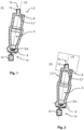
- Fig. 1 shows a sectional view of a pre-chamber insert 1 for a cylinder head 2 of the internal combustion engine.
- a lower core of the cylinder head 2 is shown in Fig. 6 .
- the pre-chamber insert 1 is prefabricated and is cast into the cylinder head 2 and thereby integrated in a materially bonded manner into the cylinder head 2.
- the pre-chamber insert 1 can be prefabricated, for example, in a 3D printing method or in a casting method.
- the pre-chamber insert 1 contains an internal pre-chamber 4 and two ends 1a and 1b which are opposite one another with respect to a longitudinal central axis LA of the pre-chamber insert 1. If the pre-chamber insert 1 is cast in the cylinder head 2 - see Fig. 10 and Fig. 11 - the first end 1a faces a combustion chamber and the second end 1b faces away from the combustion chamber.
- a plurality of openings 5 are formed in the form of nozzles 6.
- the respective nozzles 6 are directed outwardly from the pre-chamber 4 into the combustion chamber.
- an opening 5 is formed in the form of a spark plug opening 7.
- the spark plug opening 7 is provided for inserting a spark plug into the pre-chamber 4.
- the two openings 5 are closed each by a protective region 8.
- the protective regions 8 are removed after the pre-chamber insert 1 has been materially bonded into the cylinder head 2. Thereby, the openings 5 are exposed to the outside.
- a positioning unit 15 is also formed on each end 1a and 1b of the pre-chamber insert 1.
- the pre-chamber insert 1 can be arranged in a correct position in the cylinder head 2.
- the positioning units 15 are thereby in each case a part of the respective protective region 8 and are also removed when the respective protective region 8 is removed.
- Fig. 2 shows a sectional view of the pre-chamber insert 1 according to the invention.
- cut lines for removing the protective regions 8 are marked separately with solid lines.
- Fig. 3 shows a sectional view of the pre-chamber insert 1 according to the invention with a further opening 5.
- the further opening 5 can here be a purge opening 9a for introducing purge air, or a gas recirculation opening 9b for introducing recirculated exhaust gas, or a fuel opening 9c for introducing a gaseous or alternative secondary fuel into the pre-chamber 4.
- a valve system in the form of a check valve 10 is also provided at the opening 5.
- Fig. 4 shows a sectional view of the pre-chamber insert 1 according to the invention in the region of the nozzles 6.
- the protective region 8 has already been removed here and the nozzles 6 are exposed to the outside.
- the nozzles 6 of the pre-chamber insert 1 can differ in shape, in size and in orientation.
- Fig. 5 shows a view of a cylinder head mould 11 for the method 3 according to the invention.
- the prefabricated pre-chamber insert 1 is arranged in the correct position in the cylinder head mould 11.
- a casting material is poured into the cylinder head mould 11, thereby casting the cylinder head 2 with the materially bonded pre-chamber insert 1.
- the protective regions 8 described above protect the pre-chamber 4 from penetration of the casting material and are removed after the pre-chamber insert 1 has been materially bonded into the cylinder head 2.
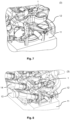
- Fig. 6 to Fig. 9 show partial views of the cylinder head mould 11.
- Fig. 6 shows the cylinder head mould 11 with the pre-chamber insert 1 arranged in the correct position.
- Fig. 7 shows the cylinder head mould 11 with a water jacket core 12.
- Fig. 8 shows the cylinder head mould 11 with an inlet core 13 and an exhaust core 14.
- Fig. 9 shows the cylinder head mould 11, wherein individual elements are aligned with each other inter alia by the positioning unit 15.
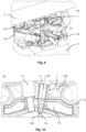
- Fig. 10 shows a sectional view of the cylinder head 2 according to the invention on the pre-chamber insert 1.
- Fig. 11 shows a further sectional view of the cylinder head 2 on the pre-chamber insert 1 in a deviating sectional plane.
- the cylinder head 2 contains the water jacket 12a formed therein by the water jacket core 12 and the pre-chamber insert 1 contains a cooling channel unit 16 formed therein.
- the cooling channel unit 16 is arranged very close to the pre-chamber 4 of the pre-chamber insert 1 so that the temperature in the pre-chamber 4 can be better maintained.
- the wall of the cooling channel unit 16 can be small, thereby intensifying the heat transfer between the cooling channel unit 16 and the cylinder head 2.
- Fig. 12 shows a view of the pre-chamber insert 1 according to the invention.
- an ignition source holder 17 and an injector holder 18 are integrally manufactured on the pre-chamber insert 1.
- the ignition source holder 17 contains an internal receiving space and is provided for receiving a secondary ignition source - for example, another spark plug - for the combustion chamber.
- the injector holder 18 similarly contains a receiving space and is provided for receiving a fuel injector for the combustion chamber.
- the receiving space in the ignition source holder 17, the receiving space in the injector holder 18, the nozzles 6 at the first end 1a, and the spark plug opening 7 at the second end 1b are closed by protective regions 8 and are thereby protected from the penetration of the casting material during the casting of the cylinder head 2.
- the protective regions 8 are removed and the receiving spaces as well as the nozzles 6 and the spark plug opening 7 are exposed i.e. opened to the outside.
- the pre-chamber insert 1 can here be filled with a filling material to withstand the internal pressure during casting of the cylinder head 2.
- Fig. 13 shows a sectional view of the pre-chamber insert 1 shown in Fig. 12 .
- Fig. 14 shows a further sectional view of the pre-chamber insert 1 shown in Fig. 12 .
- the cooling channel unit 16 extends around the pre-chamber insert 1, whereby the cooling of the pre-chamber insert 1 is improved.
Landscapes
- Engineering & Computer Science (AREA)
- Mechanical Engineering (AREA)
- Chemical & Material Sciences (AREA)
- Combustion & Propulsion (AREA)
- General Engineering & Computer Science (AREA)
- Cylinder Crankcases Of Internal Combustion Engines (AREA)
- Combustion Methods Of Internal-Combustion Engines (AREA)
Abstract
Description
- The invention relates to a method of manufacturing a cylinder head according to the generic term of
claim 1. The invention also relates to the cylinder head and a pre-chamber insert for the cylinder head. - In an internal combustion engine, a fuel is ignited in a combustion chamber by means of a spark plug arranged in the cylinder head. Often a pre-chamber is also formed in the cylinder head and is arranged between the spark plug and the combustion chamber. Part of the fuel is then ignited in the pre-chamber and is ejected through nozzles into the combustion chamber. Then, the remaining fuel in the combustion chamber is ignited by the ejected part of the fuel. The pre-chamber requires a complex integral geometry and must be accurately positioned in the cylinder head. With current manufacturing methods, it is disadvantageously not possible to realize a complex geometry of the pre-chamber. Particularly problematic is the alignment of the individual nozzles, which directly influences ignition in the combustion chamber.
- It is therefore the object of the invention to provide a method of manufacturing a cylinder head in which the disadvantages described are overcome.
- This object is solved according to the invention by the object of the independent claims. Advantageous embodiments are the subject of the dependent claims.
- The present invention is based on the general idea of prefabrication of a pre-chamber for a cylinder head with all the required internal features and then casting it into the cylinder head. The method according to the invention is provided for manufacturing a cylinder head for an internal combustion engine. In the method, a pre-chamber insert with an internal pre-chamber is prefabricated and arranged in the correct position in a cylinder head mould. Thereafter, a casting material is filled into the cylinder head mould with the arranged pre-chamber insert and thereby the cylinder head with the materially bonded pre-chamber insert for the internal combustion engine is casted.
- In the internal combustion engine, the combustion chamber is not a part of the cylinder head but is partially limited to the outside by the cylinder head. However, the position of the combustion chamber can be seen on the cylinder head, so that here and after a reference is made to the combustion chamber.
- In the method according to the invention, the pre-chamber insert can be manufactured independently of the cylinder head with all the required internal features and all the required external features. As a result, the pre-chamber can contain a configuration of almost any complexity. In particular, the nozzles leading from the pre-chamber into a combustion chamber can be asymmetrically shaped and/or different in size and/or different in shape. Moreover, the orientation of the nozzles can be adapted according to the requirements. Overall, this can improve the ignition in the internal combustion engine. In addition, the pre-chamber insert is materially bonded to the cylinder head, so that a heat transfer between the cylinder head and the pre-chamber is also optimized. As a result, the temperature in the pre-chamber can be better controlled. The method according to the invention is applicable for manufacturing cylinder heads for differently designed internal combustion engines with a pre-chamber.
- Advantageously, the pre-chamber insert can be prefabricated by means of 3D printing. 3D printing can be used for both passive and active applications. The pre-chamber insert can thereby be manufactured ready for use and further post-methoding - for example, for manufacturing internal features of the pre-chamber - can be avoided. Moreover, the nozzles leading from the pre-chamber into a combustion chamber can be shaped asymmetrically and/or differently in size and/or differently in shape. Moreover, with 3D printing, the orientation of the nozzles can also be adapted according to the requirements. Alternatively, the pre-chamber insert can be prefabricated by means of a casting method. Regardless of the manufacturing method, the pre-chamber insert can be made of steel or non-ferrous materials.
- In one embodiment of the method, it can be provided that during the prefabrication of the pre-chamber insert, at least one opening closed to the outside by means of a protective region is prefabricated. After the materially bonding of the pre-chamber insert has been into the cylinder head, the protective region is removed and the at least one opening is opened to the outside. The protective region can thereby protect the pre-chamber from penetration of the casting material during casting of the cylinder head.
- For example, the protective region can be integrally manufactured with the pre-chamber insert. In particular, this can be used by fabricating the pre-chamber insert by means of 3D printing. Alternatively, the protective region can be manufactured separately from the pre-chamber insert and can be attached to the prefabricated pre-chamber insert by material bonding, preferably by welding. In this case, the protective region can be prefabricated in the form of a cover cap. The material of the cover cap can be identical to the material of the pre-chamber insert or can differ therefrom.
- Possible embodiments of the at least one opening are listed below. In principle, one or more openings can be formed in the pre-chamber insert in one or more embodiments. The embodiment and the number of the respective openings can thereby differ depending on the requirements. It is understood that this list is not exhaustive.
- The at least one opening can be prefabricated in the form of a gas recirculation opening for introducing recirculated exhaust gas. The at least one opening can also be prefabricated in the form of a purge opening for introducing purge air into the pre-chamber. The at least one opening can be prefabricated in the form of a fuel opening for introducing a gaseous or alternative secondary fuel. To form the openings described above, a bore with a valve system can be formed in the pre-chamber insert. The valve system can then allow passive or active introduction of exhaust gas or purge air or secondary fuel. Alternatively or additionally, the at least one opening can be prefabricated in the form of an instrument opening for arranging of at least one additional instrument. Preferably, the at least one instrument can be a temperature sensor and/or a pressure sensor and/or a combustion air ratio sensor. The at least one opening can be prefabricated at an end of the pre-chamber insert facing a combustion chamber in the form of a nozzle leading into the combustion chamber. Thereby, a plurality of nozzles can be prefabricated, wherein the nozzles can differ from each other in shape and/or in size and/or in orientation. For example, the nozzles can have a different angle of inclination with respect to a longitudinal central axis of the pre-chamber insert and/or a different diameter and/or a cylindrical or conical or other shape. The at least one opening can be prefabricated at an end of the pre-chamber insert facing away from a combustion chamber in the form of a spark plug opening. The spark plug can then be inserted into the pre-chamber through the spark plug opening.
- In an advantageous embodiment of the method, it can be provided that during prefabrication of the pre-chamber insert, a filling material is filled into the internal pre-chamber. After the pre-chamber insert has been materially bonded into the cylinder head, the filling material is removed from the internal pre-chamber. The filling material can be filled into the pre-chamber during prefabrication and the pre-chamber can be closed with the protective region described above. Preferably, the filling material is inert and does not affect the fabrication of the cylinder head. The filling material can be removed after removal of the respective protective region through the at least one opening thus opened. The filling material can protect the pre-chamber insert from internal pressure during casting, or at least reduce the internal pressure during casting.
- During the prefabrication of the pre-chamber insert, at least one rotationally asymmetric positioning unit can be fabricated on an outer side of the pre-chamber insert. In this regard, the positioning unit can be fabricated at an end of the pre-chamber insert facing a combustion chamber or at an end of the pre-chamber insert facing away from a combustion chamber. When arranging the pre-chamber insert in the cylinder head mould, the pre-chamber insert can then be arranged in the correct position in the cylinder head mould by means of the at least one rotationally asymmetrical positioning unit. In particular, it is conceivable that at least two positioning units are provided at each end of the pre-chamber insert. Advantageously, the at least one positioning unit can be formed in the protective region or as the protective region and can be removed after the pre-chamber insert has been materially bonded into the cylinder head.
- In an advantageous embodiment of the method, it can be provided that during the prefabrication of the pre-chamber insert, at least one additional element is integrally manufactured on the pre-chamber insert. Possible embodiments of the element are listed below. In principle, several elements listed below can be combined in the pre-chamber insert according to the requirements. It is understood that this list is not exhaustive.
- During the prefabricating the pre-chamber insert, an ignition source holder for receiving a secondary ignition source for a combustion chamber can be integrally fabricated on the pre-chamber insert. During the prefabricating the pre-chamber insert, an injector holder for receiving a fuel injector for a combustion chamber can also be integrally fabricated on the pre-chamber insert. Further, a cooling channel unit with a channel for cooling guidance can be integrally fabricated on the pre-chamber insert. During the prefabricating the pre-chamber insert, a preheating channel unit with a channel for preheating the pre-chamber can also be integrally manufactured on the pre-chamber insert. In principle, the cooling channel unit and the preheating channel unit can be implemented by a single or common unit. The cooling channel unit and the preheating channel unit enable cooling and preheating of the pre-chamber independently of the cylinder head. Further, during the prefabrication of the pre-chamber insert, at least one external retention unit can be integrally manufactured on the pre-chamber insert. In this regard, the retention unit can include a plurality of retention elements to enhance the retention i.e. materially binding of the pre-chamber insert in the cylinder head. Further, during the prefabrication of the pre-chamber insert, a holding unit for holding an electrical heating element can also be integrally manufactured on the pre-chamber insert.
- By manufacturing the above elements with the pre-chamber insert, these elements can be closely coupled to each other. The cooling channel unit and/or the preheating channel unit closely coupled to the pre-chamber and optionally to further elements can significantly improve the cooling and/or the preheating of the pre-chamber and optionally of the further elements. Furthermore, the need for external housings for said elements is reduced. Overall, the manufacturing of the cylinder head is thereby simplified.
- The invention also relates to a cylinder head for an internal combustion engine, wherein the cylinder head is manufactured by means of the method described above. The invention also relates to the pre-chamber insert for the cylinder head of an internal combustion engine, wherein the pre-chamber insert is adapted to manufacture the cylinder head by means of the method described above.
- Other important features and advantages of the invention will be apparent from the sub-claims, from the drawings and from the accompanying figure description with reference to the drawings.
- It is understood that the above features, and those to be explained below, can be used not only in the combination indicated in each case, but also in other combinations or alone, without departing from the scope of the present invention.
- Preferred embodiments of the invention are shown in the drawings and will be explained in more detail in the following description, wherein identical reference signs refer to identical or similar or functionally identical components.
- It shows, schematically in each case
- Fig. 1
- a sectional view of a pre-chamber insert according to the invention;
- Fig. 2
- a sectional view of the pre-chamber insert according to the invention with indicative machined protective regions;
- Fig. 3
- a sectional view of the pre-chamber insert according to the invention with an additional functional opening for passive purge;
- Fig. 4
- a sectional view of the pre-chamber insert according to the invention in the region of a nozzle;
- Fig. 5
- a view of a combustion chamber in a cylinder head for a method according to the invention;
- Figs. 6 to 9
- partial views of the cylinder head mould with different mounted mould core elements;
- Figs. 10 and 11
- sectional views of a cylinder head according to the invention on the pre-chamber insert according to the invention with additional close coupled pre-chamber and cooling channel unit;
- Fig. 12
- a view of the pre-chamber insert according to the invention with an ignition source holder and an injector holder;
- Figs. 13 and 14
- sectional views of the pre-chamber insert of
Fig. 12 according to the invention in different sectional planes. -
Fig. 1 shows a sectional view of apre-chamber insert 1 for acylinder head 2 of the internal combustion engine. A lower core of thecylinder head 2 is shown inFig. 6 . In amethod 3, thepre-chamber insert 1 is prefabricated and is cast into thecylinder head 2 and thereby integrated in a materially bonded manner into thecylinder head 2. Thepre-chamber insert 1 can be prefabricated, for example, in a 3D printing method or in a casting method. Thepre-chamber insert 1 contains aninternal pre-chamber 4 and twoends pre-chamber insert 1. If thepre-chamber insert 1 is cast in the cylinder head 2 - seeFig. 10 andFig. 11 - thefirst end 1a faces a combustion chamber and thesecond end 1b faces away from the combustion chamber. - At the
first end 1a of thepre-chamber insert 1, a plurality of openings 5 are formed in the form of nozzles 6. The respective nozzles 6 are directed outwardly from thepre-chamber 4 into the combustion chamber. At the second end 2a, an opening 5 is formed in the form of a spark plug opening 7. The spark plug opening 7 is provided for inserting a spark plug into thepre-chamber 4. InFig. 1 , the two openings 5 are closed each by aprotective region 8. In themethod 3, theprotective regions 8 are removed after thepre-chamber insert 1 has been materially bonded into thecylinder head 2. Thereby, the openings 5 are exposed to the outside. - A
positioning unit 15 is also formed on eachend pre-chamber insert 1. By means of thepositioning units 15, thepre-chamber insert 1 can be arranged in a correct position in thecylinder head 2. Thepositioning units 15 are thereby in each case a part of the respectiveprotective region 8 and are also removed when the respectiveprotective region 8 is removed. -
Fig. 2 shows a sectional view of thepre-chamber insert 1 according to the invention. InFig. 2 , cut lines for removing theprotective regions 8 are marked separately with solid lines. -
Fig. 3 shows a sectional view of thepre-chamber insert 1 according to the invention with a further opening 5. The further opening 5 can here be a purge opening 9a for introducing purge air, or a gas recirculation opening 9b for introducing recirculated exhaust gas, or a fuel opening 9c for introducing a gaseous or alternative secondary fuel into thepre-chamber 4. A valve system in the form of acheck valve 10 is also provided at the opening 5. -
Fig. 4 shows a sectional view of thepre-chamber insert 1 according to the invention in the region of the nozzles 6. Theprotective region 8 has already been removed here and the nozzles 6 are exposed to the outside. The nozzles 6 of thepre-chamber insert 1 can differ in shape, in size and in orientation. -
Fig. 5 shows a view of acylinder head mould 11 for themethod 3 according to the invention. According to themethod 3, the prefabricatedpre-chamber insert 1 is arranged in the correct position in thecylinder head mould 11. Then, a casting material is poured into thecylinder head mould 11, thereby casting thecylinder head 2 with the materially bondedpre-chamber insert 1. Theprotective regions 8 described above protect the pre-chamber 4 from penetration of the casting material and are removed after thepre-chamber insert 1 has been materially bonded into thecylinder head 2. -
Fig. 6 to Fig. 9 show partial views of thecylinder head mould 11.Fig. 6 shows thecylinder head mould 11 with thepre-chamber insert 1 arranged in the correct position.Fig. 7 shows thecylinder head mould 11 with awater jacket core 12.Fig. 8 shows thecylinder head mould 11 with aninlet core 13 and anexhaust core 14.Fig. 9 shows thecylinder head mould 11, wherein individual elements are aligned with each other inter alia by thepositioning unit 15. -
Fig. 10 shows a sectional view of thecylinder head 2 according to the invention on thepre-chamber insert 1.Fig. 11 shows a further sectional view of thecylinder head 2 on thepre-chamber insert 1 in a deviating sectional plane. Here, thecylinder head 2 contains thewater jacket 12a formed therein by thewater jacket core 12 and thepre-chamber insert 1 contains acooling channel unit 16 formed therein. Thus, thecylinder head 2 and thepre-chamber 4 can be effectively cooled. The coolingchannel unit 16 is arranged very close to thepre-chamber 4 of thepre-chamber insert 1 so that the temperature in thepre-chamber 4 can be better maintained. In addition, the wall of the coolingchannel unit 16 can be small, thereby intensifying the heat transfer between the coolingchannel unit 16 and thecylinder head 2. -
Fig. 12 shows a view of thepre-chamber insert 1 according to the invention. Here, anignition source holder 17 and aninjector holder 18 are integrally manufactured on thepre-chamber insert 1. Here, theignition source holder 17 contains an internal receiving space and is provided for receiving a secondary ignition source - for example, another spark plug - for the combustion chamber. Theinjector holder 18 similarly contains a receiving space and is provided for receiving a fuel injector for the combustion chamber. - The receiving space in the
ignition source holder 17, the receiving space in theinjector holder 18, the nozzles 6 at thefirst end 1a, and the spark plug opening 7 at thesecond end 1b are closed byprotective regions 8 and are thereby protected from the penetration of the casting material during the casting of thecylinder head 2. After casting, theprotective regions 8 are removed and the receiving spaces as well as the nozzles 6 and the spark plug opening 7 are exposed i.e. opened to the outside. Thepre-chamber insert 1 can here be filled with a filling material to withstand the internal pressure during casting of thecylinder head 2. -
Fig. 13 shows a sectional view of thepre-chamber insert 1 shown inFig. 12 .Fig. 14 shows a further sectional view of thepre-chamber insert 1 shown inFig. 12 . As can be seen particularly well inFig. 13 and Fig. 14 , the coolingchannel unit 16 extends around thepre-chamber insert 1, whereby the cooling of thepre-chamber insert 1 is improved.
Claims (12)
- A method (3) of manufacturing a cylinder head (2) for an internal combustion engine,- wherein a pre-chamber insert (1) with an internal pre-chamber (4) is prefabricated and arranged in the correct position in a cylinder head mould (11);- wherein a casting material is filled into the cylinder head mould (11) with the arranged pre-chamber insert (1) and thereby the cylinder head (2) with the materially bonded pre-chamber insert (1) for the internal combustion engine is casted.
- Method according to claim 1,
characterized
in that the pre-chamber insert (1) is prefabricated by means of a 3D printing or casting method. - Method according to claim 1 or 2,
characterized- in that during the prefabrication of the pre-chamber insert (1) at least one opening (5) is prefabricated, wherein the at least one opening (5) is closed to the outside by means of a protective region (8);- in that after the materially bonding of the pre-chamber insert (1) into the cylinder head (2), the protective region (8) is removed and the at least one opening (5) is opened to the outside. - Method according to claim 3,
characterized- in that the protective region (8) is manufactured integral with the pre-chamber insert (1); and/or- in that the protective region (8) is manufactured separately from the pre-chamber insert (1) and is fastened to the prefabricated pre-chamber insert (1) by a materially bonding, preferably by welding. - Method according to claim 3 or 4,
characterized- in that the at least one opening (5) is prefabricated at an end (1a) of the pre-chamber insert (1) facing a combustion chamber in the form of a nozzle (6) leading into the combustion chamber; and/or- in that the at least one opening (5) is prefabricated at an end (1b) of the pre-chamber insert (1) facing away from a combustion chamber in the form of a spark plug opening (7); and/or- in that the at least one opening (5) is prefabricated in the form of a purge opening (9a) for the introduction of purge air; and/or- in that the at least one opening (5) is prefabricated in the form of a gas recirculation opening (9b) for the introduction of recirculated exhaust gas; and/or- in that the at least one opening (5) is prefabricated in the form of a fuel opening (9c) for the introduction of a gaseous or alternative secondary fuel; and/or- in that the at least one opening (5) is prefabricated in the form of an instrument opening for arranging of at least one additional instrument, preferably a temperature sensor and/or a pressure sensor and/or a combustion air ratio sensor. - Method according to any one of the preceding claims,
characterized- in that during the prefabrication of the pre-chamber insert (1), a filling material is filled into the inner pre-chamber (4), and- in that after the materially bonding of the pre-chamber insert (1) into the cylinder head (2), the filling material is removed from the inner pre-chamber (4). - Method according to any one of the preceding claims,
characterized- in that during the prefabrication of the pre-chamber insert (1), at least one rotationally asymmetrical positioning unit (15) is fabricated on an end (1a) of the pre-chamber insert (1) facing a combustion chamber or on an end (1b) of the pre-chamber insert (1) facing away from the combustion chamber on an outer side of the pre-chamber insert (1); and- in that when arranging the pre-chamber insert (1) in the cylinder head mould (11), the pre-chamber insert (1) is arranged in the correct position in the cylinder head mould (11) by means of the at least one rotationally asymmetrical positioning unit (15). - Method according to claim 3 and 7,
characterized
in that the at least one positioning unit is formed in the protective region (8) or as the protective region (8) and is removed after the pre-chamber insert (1) has been materially bonded into the cylinder head (2). - Method according to any one of the preceding claims,
characterized- in that during the prefabrication of the pre-chamber insert (1), an ignition source holder (17) for receiving a secondary ignition source for a combustion chamber is integrally manufactured on the pre-chamber insert (1); and/or- in that during the prefabrication of the pre-chamber insert (1), an injector holder (18) for receiving a fuel injector for a combustion chamber is integrally manufactured on the pre-chamber insert (1); and/or- in that during the prefabrication of the pre-chamber insert (1), a cooling channel unit (16) with a channel for cooling guidance is integrally manufactured on the pre-chamber insert (1); and/or- in that during the prefabrication of the pre-chamber insert (1), a preheating channel unit with a channel for preheating the pre-chamber is integrally manufactured on the pre-chamber insert (1); and/or- in that during the prefabrication of the pre-chamber insert (1), at least one external retention unit is integrally manufactured on the pre-chamber insert (1); and/or- in that during the prefabrication of the pre-chamber insert (1), a holding unit for holding an electric heating element is integrally manufactured on the pre-chamber insert (1). - Method according to any one of the preceding claims,
characterized
in that during the prefabrication of the pre-chamber insert (1), a fuel injector seal is arranged in the inner pre-chamber (4). - A cylinder head (2) for an internal combustion engine, wherein the cylinder head (2) is manufactured by means of the method (3) according to any one of the preceding claims.
- A pre-chamber insert (1) for a cylinder head (2) of an internal combustion engine, wherein the pre-chamber insert (1) is adapted to produce the cylinder head (2) by means of the method (3) according to any one of claims 1 to 10.
Priority Applications (2)
| Application Number | Priority Date | Filing Date | Title |
|---|---|---|---|
| EP22201681.8A EP4353961A1 (en) | 2022-10-14 | 2022-10-14 | Method of manufacturing a cylinder head |
| CN202311269110.3A CN117884579A (en) | 2022-10-14 | 2023-09-27 | Method for manufacturing cylinder head |
Applications Claiming Priority (1)
| Application Number | Priority Date | Filing Date | Title |
|---|---|---|---|
| EP22201681.8A EP4353961A1 (en) | 2022-10-14 | 2022-10-14 | Method of manufacturing a cylinder head |
Publications (1)
| Publication Number | Publication Date |
|---|---|
| EP4353961A1 true EP4353961A1 (en) | 2024-04-17 |
Family
ID=83898239
Family Applications (1)
| Application Number | Title | Priority Date | Filing Date |
|---|---|---|---|
| EP22201681.8A Pending EP4353961A1 (en) | 2022-10-14 | 2022-10-14 | Method of manufacturing a cylinder head |
Country Status (2)
| Country | Link |
|---|---|
| EP (1) | EP4353961A1 (en) |
| CN (1) | CN117884579A (en) |
Citations (4)
| Publication number | Priority date | Publication date | Assignee | Title |
|---|---|---|---|---|
| US4044730A (en) * | 1974-11-13 | 1977-08-30 | Toyota Jidosha Kogyo Kabushiki Kaisha | Auxiliary combustion chamber for an internal combustion engine |
| DE2636659A1 (en) * | 1976-08-14 | 1978-02-16 | Daimler Benz Ag | External ignition piston engine with injection chamber - injects two jets during compression and spark ignites in pre-chamber to give two-stage ignition |
| US5778849A (en) * | 1997-05-05 | 1998-07-14 | Chrysler Corporation | Insulated precombustion chamber |
| KR20210031018A (en) * | 2019-09-10 | 2021-03-19 | 현대자동차주식회사 | Ignition promoter device of engine |
-
2022
- 2022-10-14 EP EP22201681.8A patent/EP4353961A1/en active Pending
-
2023
- 2023-09-27 CN CN202311269110.3A patent/CN117884579A/en active Pending
Patent Citations (4)
| Publication number | Priority date | Publication date | Assignee | Title |
|---|---|---|---|---|
| US4044730A (en) * | 1974-11-13 | 1977-08-30 | Toyota Jidosha Kogyo Kabushiki Kaisha | Auxiliary combustion chamber for an internal combustion engine |
| DE2636659A1 (en) * | 1976-08-14 | 1978-02-16 | Daimler Benz Ag | External ignition piston engine with injection chamber - injects two jets during compression and spark ignites in pre-chamber to give two-stage ignition |
| US5778849A (en) * | 1997-05-05 | 1998-07-14 | Chrysler Corporation | Insulated precombustion chamber |
| KR20210031018A (en) * | 2019-09-10 | 2021-03-19 | 현대자동차주식회사 | Ignition promoter device of engine |
Also Published As
| Publication number | Publication date |
|---|---|
| CN117884579A (en) | 2024-04-16 |
Similar Documents
| Publication | Publication Date | Title |
|---|---|---|
| KR101030197B1 (en) | Cylinder head and method of manufacturing the cylinder head | |
| US9217360B2 (en) | Prechamber device for internal combustion engine | |
| CN102312751B (en) | Cooling device of water-cooled engine and method of manufacturing the same | |
| US6681727B2 (en) | Cylinder head for a plurality of cylinders | |
| EP1979590B1 (en) | Internal combustion engine | |
| US20110277708A1 (en) | Cylinder Head for Internal Combustion Engine | |
| US9574522B2 (en) | Assembly with cylinder head having integrated exhaust manifold and method of manufacturing same | |
| EP3051092B1 (en) | Cooling of pre-chamber in internal combustion engine | |
| EP0693619A1 (en) | Cylinder head of engine | |
| JP2016173107A (en) | Cylinder head for an internal combustion engine having a cooling channel | |
| TWI672436B (en) | Cylinder head | |
| US20120073528A1 (en) | Cylinder Head Having Water Jacket | |
| JP4655033B2 (en) | Internal combustion engine | |
| US10731597B2 (en) | Cylinder head for internal combustion engine | |
| CN117884579A (en) | Method for manufacturing cylinder head | |
| KR19990029142A (en) | Manufacturing method of cylinder head of internal combustion engine | |
| US20080271700A1 (en) | Cylinder head and production method for a cylinder head | |
| EP1135587B1 (en) | Internal combustion engine cylinder head cooled with liquid | |
| JP2019173704A (en) | Guide member, engine and method for manufacturing engine | |
| US6412452B1 (en) | Liquid cooled cylinder head | |
| CN116113756A (en) | cylinder head | |
| EP4015810B1 (en) | Cylinder head, multi-cylinder engine, vehicle, and method of manufacturing cylinder head | |
| JP2001065352A (en) | Structure of uniflow type two-cycle internal combustion engine | |
| JP2002213300A (en) | Engine cooling structure and method of manufacturing cooling water passage | |
| SE541831C2 (en) | A Cylinder Head for an Internal Combustion Engine |
Legal Events
| Date | Code | Title | Description |
|---|---|---|---|
| PUAI | Public reference made under article 153(3) epc to a published international application that has entered the european phase |
Free format text: ORIGINAL CODE: 0009012 |
|
| STAA | Information on the status of an ep patent application or granted ep patent |
Free format text: STATUS: THE APPLICATION HAS BEEN PUBLISHED |
|
| AK | Designated contracting states |
Kind code of ref document: A1 Designated state(s): AL AT BE BG CH CY CZ DE DK EE ES FI FR GB GR HR HU IE IS IT LI LT LU LV MC ME MK MT NL NO PL PT RO RS SE SI SK SM TR |
|
| STAA | Information on the status of an ep patent application or granted ep patent |
Free format text: STATUS: REQUEST FOR EXAMINATION WAS MADE |
|
| 17P | Request for examination filed |
Effective date: 20241016 |
|
| RBV | Designated contracting states (corrected) |
Designated state(s): AL AT BE BG CH CY CZ DE DK EE ES FI FR GB GR HR HU IE IS IT LI LT LU LV MC ME MK MT NL NO PL PT RO RS SE SI SK SM TR |