EP4353950A2 - Blade outer air seal with cooling channels - Google Patents
Blade outer air seal with cooling channels Download PDFInfo
- Publication number
- EP4353950A2 EP4353950A2 EP23203246.6A EP23203246A EP4353950A2 EP 4353950 A2 EP4353950 A2 EP 4353950A2 EP 23203246 A EP23203246 A EP 23203246A EP 4353950 A2 EP4353950 A2 EP 4353950A2
- Authority
- EP
- European Patent Office
- Prior art keywords
- component
- internal channel
- extending
- cooling
- blade outer
- Prior art date
- Legal status (The legal status is an assumption and is not a legal conclusion. Google has not performed a legal analysis and makes no representation as to the accuracy of the status listed.)
- Pending
Links
- 238000001816 cooling Methods 0.000 title claims abstract description 52
- 238000004891 communication Methods 0.000 claims abstract description 14
- 239000012530 fluid Substances 0.000 claims abstract description 13
- 239000007789 gas Substances 0.000 description 24
- 239000000446 fuel Substances 0.000 description 5
- 239000000567 combustion gas Substances 0.000 description 4
- 239000000463 material Substances 0.000 description 3
- 238000012546 transfer Methods 0.000 description 3
- 239000000284 extract Substances 0.000 description 2
- 238000004519 manufacturing process Methods 0.000 description 2
- 238000000034 method Methods 0.000 description 2
- 230000009467 reduction Effects 0.000 description 2
- 230000003068 static effect Effects 0.000 description 2
- 230000008859 change Effects 0.000 description 1
- 230000006835 compression Effects 0.000 description 1
- 238000007906 compression Methods 0.000 description 1
- 238000012937 correction Methods 0.000 description 1
- 230000001627 detrimental effect Effects 0.000 description 1
- 238000005259 measurement Methods 0.000 description 1
- 230000007246 mechanism Effects 0.000 description 1
- 238000012986 modification Methods 0.000 description 1
- 230000004048 modification Effects 0.000 description 1
- 230000004044 response Effects 0.000 description 1
Images


Classifications
-
- F—MECHANICAL ENGINEERING; LIGHTING; HEATING; WEAPONS; BLASTING
- F01—MACHINES OR ENGINES IN GENERAL; ENGINE PLANTS IN GENERAL; STEAM ENGINES
- F01D—NON-POSITIVE DISPLACEMENT MACHINES OR ENGINES, e.g. STEAM TURBINES
- F01D11/00—Preventing or minimising internal leakage of working-fluid, e.g. between stages
- F01D11/08—Preventing or minimising internal leakage of working-fluid, e.g. between stages for sealing space between rotor blade tips and stator
- F01D11/14—Adjusting or regulating tip-clearance, i.e. distance between rotor-blade tips and stator casing
- F01D11/20—Actively adjusting tip-clearance
- F01D11/24—Actively adjusting tip-clearance by selectively cooling-heating stator or rotor components
-
- F—MECHANICAL ENGINEERING; LIGHTING; HEATING; WEAPONS; BLASTING
- F01—MACHINES OR ENGINES IN GENERAL; ENGINE PLANTS IN GENERAL; STEAM ENGINES
- F01D—NON-POSITIVE DISPLACEMENT MACHINES OR ENGINES, e.g. STEAM TURBINES
- F01D11/00—Preventing or minimising internal leakage of working-fluid, e.g. between stages
- F01D11/08—Preventing or minimising internal leakage of working-fluid, e.g. between stages for sealing space between rotor blade tips and stator
-
- F—MECHANICAL ENGINEERING; LIGHTING; HEATING; WEAPONS; BLASTING
- F01—MACHINES OR ENGINES IN GENERAL; ENGINE PLANTS IN GENERAL; STEAM ENGINES
- F01D—NON-POSITIVE DISPLACEMENT MACHINES OR ENGINES, e.g. STEAM TURBINES
- F01D25/00—Component parts, details, or accessories, not provided for in, or of interest apart from, other groups
- F01D25/08—Cooling; Heating; Heat-insulation
- F01D25/12—Cooling
-
- F—MECHANICAL ENGINEERING; LIGHTING; HEATING; WEAPONS; BLASTING
- F01—MACHINES OR ENGINES IN GENERAL; ENGINE PLANTS IN GENERAL; STEAM ENGINES
- F01D—NON-POSITIVE DISPLACEMENT MACHINES OR ENGINES, e.g. STEAM TURBINES
- F01D5/00—Blades; Blade-carrying members; Heating, heat-insulating, cooling or antivibration means on the blades or the members
- F01D5/12—Blades
- F01D5/14—Form or construction
- F01D5/18—Hollow blades, i.e. blades with cooling or heating channels or cavities; Heating, heat-insulating or cooling means on blades
- F01D5/186—Film cooling
-
- F—MECHANICAL ENGINEERING; LIGHTING; HEATING; WEAPONS; BLASTING
- F01—MACHINES OR ENGINES IN GENERAL; ENGINE PLANTS IN GENERAL; STEAM ENGINES
- F01D—NON-POSITIVE DISPLACEMENT MACHINES OR ENGINES, e.g. STEAM TURBINES
- F01D5/00—Blades; Blade-carrying members; Heating, heat-insulating, cooling or antivibration means on the blades or the members
- F01D5/12—Blades
- F01D5/14—Form or construction
- F01D5/18—Hollow blades, i.e. blades with cooling or heating channels or cavities; Heating, heat-insulating or cooling means on blades
- F01D5/187—Convection cooling
-
- F—MECHANICAL ENGINEERING; LIGHTING; HEATING; WEAPONS; BLASTING
- F05—INDEXING SCHEMES RELATING TO ENGINES OR PUMPS IN VARIOUS SUBCLASSES OF CLASSES F01-F04
- F05D—INDEXING SCHEME FOR ASPECTS RELATING TO NON-POSITIVE-DISPLACEMENT MACHINES OR ENGINES, GAS-TURBINES OR JET-PROPULSION PLANTS
- F05D2220/00—Application
- F05D2220/30—Application in turbines
- F05D2220/32—Application in turbines in gas turbines
-
- F—MECHANICAL ENGINEERING; LIGHTING; HEATING; WEAPONS; BLASTING
- F05—INDEXING SCHEMES RELATING TO ENGINES OR PUMPS IN VARIOUS SUBCLASSES OF CLASSES F01-F04
- F05D—INDEXING SCHEME FOR ASPECTS RELATING TO NON-POSITIVE-DISPLACEMENT MACHINES OR ENGINES, GAS-TURBINES OR JET-PROPULSION PLANTS
- F05D2230/00—Manufacture
- F05D2230/30—Manufacture with deposition of material
-
- F—MECHANICAL ENGINEERING; LIGHTING; HEATING; WEAPONS; BLASTING
- F05—INDEXING SCHEMES RELATING TO ENGINES OR PUMPS IN VARIOUS SUBCLASSES OF CLASSES F01-F04
- F05D—INDEXING SCHEME FOR ASPECTS RELATING TO NON-POSITIVE-DISPLACEMENT MACHINES OR ENGINES, GAS-TURBINES OR JET-PROPULSION PLANTS
- F05D2240/00—Components
- F05D2240/10—Stators
- F05D2240/11—Shroud seal segments
-
- F—MECHANICAL ENGINEERING; LIGHTING; HEATING; WEAPONS; BLASTING
- F05—INDEXING SCHEMES RELATING TO ENGINES OR PUMPS IN VARIOUS SUBCLASSES OF CLASSES F01-F04
- F05D—INDEXING SCHEME FOR ASPECTS RELATING TO NON-POSITIVE-DISPLACEMENT MACHINES OR ENGINES, GAS-TURBINES OR JET-PROPULSION PLANTS
- F05D2240/00—Components
- F05D2240/55—Seals
-
- F—MECHANICAL ENGINEERING; LIGHTING; HEATING; WEAPONS; BLASTING
- F05—INDEXING SCHEMES RELATING TO ENGINES OR PUMPS IN VARIOUS SUBCLASSES OF CLASSES F01-F04
- F05D—INDEXING SCHEME FOR ASPECTS RELATING TO NON-POSITIVE-DISPLACEMENT MACHINES OR ENGINES, GAS-TURBINES OR JET-PROPULSION PLANTS
- F05D2250/00—Geometry
- F05D2250/10—Two-dimensional
- F05D2250/15—Two-dimensional spiral
-
- F—MECHANICAL ENGINEERING; LIGHTING; HEATING; WEAPONS; BLASTING
- F05—INDEXING SCHEMES RELATING TO ENGINES OR PUMPS IN VARIOUS SUBCLASSES OF CLASSES F01-F04
- F05D—INDEXING SCHEME FOR ASPECTS RELATING TO NON-POSITIVE-DISPLACEMENT MACHINES OR ENGINES, GAS-TURBINES OR JET-PROPULSION PLANTS
- F05D2260/00—Function
- F05D2260/20—Heat transfer, e.g. cooling
- F05D2260/202—Heat transfer, e.g. cooling by film cooling
-
- F—MECHANICAL ENGINEERING; LIGHTING; HEATING; WEAPONS; BLASTING
- F05—INDEXING SCHEMES RELATING TO ENGINES OR PUMPS IN VARIOUS SUBCLASSES OF CLASSES F01-F04
- F05D—INDEXING SCHEME FOR ASPECTS RELATING TO NON-POSITIVE-DISPLACEMENT MACHINES OR ENGINES, GAS-TURBINES OR JET-PROPULSION PLANTS
- F05D2260/00—Function
- F05D2260/20—Heat transfer, e.g. cooling
- F05D2260/221—Improvement of heat transfer
- F05D2260/2214—Improvement of heat transfer by increasing the heat transfer surface
- F05D2260/22141—Improvement of heat transfer by increasing the heat transfer surface using fins or ribs
Definitions
- This disclosure relates to cooling features for a component of gas turbine engine and more particularly, a component of a gas turbine engine with the aforementioned cooling features.
- Gas turbine engines typically include a compressor section, a combustor section and a turbine section. During operation, air is pressurized in the compressor section and is mixed with fuel and burned in the combustor section to generate hot combustion gases. The hot combustion gases are communicated through the turbine section, which extracts energy from the hot combustion gases to power the compressor section and other gas turbine engine loads.
- Both the compressor and turbine sections may include alternating series of rotating blades and stationary vanes that extend into the core flow path of the gas turbine engine.
- turbine blades rotate and extract energy from the hot combustion gases that are communicated along the core flow path of the gas turbine engine.
- the turbine vanes which generally do not rotate, guide the airflow and prepare it for the next set of blades.
- Blade outer air seals BOAS
- vanes vanes
- blades and other components are located in hot sections of the gas turbine engine.
- these components are cooled with cooling air that passes through an interior cavity of the component. Accordingly, it is desirable to provide a cooled hot section component with features that improves the cooling efficiency.
- a component for a gas turbine engine including: at least one internal channel extending through a first portion of the component, the at least one internal channel extending through the first portion of the component having at least one inlet opening and at least one outlet opening each being in fluid communication with the at least one internal channel extending through the first portion of the component; a plurality of cooling features extending from a surface of the at least one internal channel extending through the first portion of the component; and at least one internal channel extending through a second portion of the component, the at least one internal channel extending through the second portion of the component is in fluid communication with the at least one internal channel extending through the first portion of the component, the second portion being located on top of the first portion, the at least one internal channel extending through the second portion of the component having a plurality of openings extending from the least one internal channel extending through the second portion of the component through the plurality of cooling features to an outer surface of the component.
- the component is a blade outer air seal.
- the blade outer air seal is formed from a bottom core, a top core and an outboard face, the outboard face defining the least one inlet opening and the bottom core defining the at least one internal channel extending through the first portion of the component.
- the bottom core defines the plurality of cooling features.
- the plurality of cooling features are pedestals.
- the least one internal channel extending through the first portion of the component is a plurality of internal channels and the at least one internal channel extending through the second portion of the component is a plurality of internal channels.
- a plurality of cooling holes extend from the at least one internal channel extending through the second portion of the component to an outer end surface of the blade outer air seal.
- a component for a gas turbine engine including: at least one internal channel extending through the component, the at least one internal channel having an inlet opening and an outlet opening each being in fluid communication with the at least one internal channel, the at least one internal channel having a spiral configuration extending from the inlet opening to the outlet opening.
- the component is a blade outer air seal.
- the least one internal channel is a plurality of internal channels.
- a gas turbine engine including; a component configured to receive a cooling air flow, the component including at least one internal channel extending through a first portion of the component, the at least one internal channel extending through the first portion of the component having at least one inlet opening and at least one outlet opening each being in fluid communication with the at least one internal channel extending through the first portion of the component; a plurality of cooling features extending from a surface of the at least one internal channel; and at least one internal channel extending through a second portion of the component, the at least one internal channel extending through the second portion of the component is in fluid communication with the at least one internal channel extending through the first portion of the component, the second portion being located on top of the first portion, the at least one internal channel extending through the second portion of the component having a plurality of openings extending from the least one internal channel extending through the second portion of the component through the plurality of cooling features to an outer surface of the component.
- the component is a blade outer air seal.
- the blade outer air seal is formed from a bottom core, a top core and an outboard face, the outboard face defining the least one inlet opening and the bottom core defining the at least one internal channel extending through the first portion of the component.
- the bottom core defines the plurality of cooling features.
- the plurality of cooling features are pedestals.
- the least one internal channel extending through the first portion of the component is a plurality of internal channels and the at least one internal channel extending through the second portion of the component is a plurality of internal channels.
- a plurality of cooling holes extend from the at least one internal channel extending through the second portion of the component to an outer end surface of the blade outer air seal.
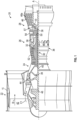
- FIG. 1 schematically illustrates a gas turbine engine 20.
- the gas turbine engine 20 is disclosed herein as a two-spool turbofan that generally incorporates a fan section 22, a compressor section 24, a combustor section 26 and a turbine section 28.
- Alternative engines might include other systems or features.
- the fan section 22 drives air along a bypass flow path B in a bypass duct, while the compressor section 24 drives air along a core flow path C1 for compression and communication into the combustor section 26 then expansion through the turbine section 28.
- the exemplary engine 20 generally includes a low speed spool 30 and a high speed spool 32 mounted for rotation about an engine central longitudinal axis A relative to an engine static structure 36 via several bearing systems 38. It should be understood that various bearing systems 38 at various locations may alternatively or additionally be provided, and the location of bearing systems 38 may be varied as appropriate to the application.
- the low speed spool 30 generally includes an inner shaft 40 that interconnects a fan 42, a first or low pressure compressor 44 and a first or low pressure turbine 46.
- the inner shaft 40 is connected to the fan 42 through a speed change mechanism, which in exemplary gas turbine engine 20 is illustrated as a geared architecture 48 to drive the fan 42 at a lower speed than the low speed spool 30.
- the high speed spool 32 includes an outer shaft 50 that interconnects a second or high pressure compressor 52 and a second or high pressure turbine 54.
- a combustor 56 is arranged in exemplary gas turbine 20 between the high pressure compressor 52 and the high pressure turbine 54.
- a mid-turbine frame 57 of the engine static structure 36 is arranged generally between the high pressure turbine 54 and the low pressure turbine 46.
- the mid-turbine frame 57 further supports bearing systems 38 in the turbine section 28.
- the inner shaft 40 and the outer shaft 50 are concentric and rotate via bearing systems 38 about the engine central longitudinal axis A which is collinear with their longitudinal axe
- the core airflow is compressed by the low pressure compressor 44 then the high pressure compressor 52, mixed and burned with fuel in the combustor 56, then expanded over the high pressure turbine 54 and low pressure turbine 46.
- the mid-turbine frame 57 includes airfoils 59 which are in the core airflow path C.
- the turbines 46, 54 rotationally drive the respective low speed spool 30 and high speed spool 32 in response to the expansion.
- gear system 48 may be located aft of combustor section 26 or even aft of turbine section 28, and fan section 22 may be positioned forward or aft of the location of gear system 48.
- the engine 20 in one example is a high-bypass geared aircraft engine.
- the engine 20 bypass ratio is greater than about six (6), with an example embodiment being greater than about ten (10)
- the geared architecture 48 is an epicyclic gear train, such as a planetary gear system or other gear system, with a gear reduction ratio of greater than about 2.3 and the low pressure turbine 46 has a pressure ratio that is greater than about five.
- the engine 20 bypass ratio is greater than about ten (10:1)
- the fan diameter is significantly larger than that of the low pressure compressor 44
- the low pressure turbine 46 has a pressure ratio that is greater than about five (5:1).
- Low pressure turbine 46 pressure ratio is pressure measured prior to inlet of low pressure turbine 46 as related to the pressure at the outlet of the low pressure turbine 46 prior to an exhaust nozzle.
- the geared architecture 48 may be an epicycle gear train, such as a planetary gear system or other gear system, with a gear reduction ratio of greater than about 2.3:1. It should be understood, however, that the above parameters are only exemplary of one embodiment of a geared architecture engine and that the present disclosure is applicable to other gas turbine engines including direct drive turbofans.
- the fan section 22 of the engine 20 is designed for a particular flight condition--typically cruise at about 0.8 Mach and about 35,000 feet (10,688 meters).
- 'TSFC' Thrust Specific Fuel Consumption
- "Low fan pressure ratio” is the pressure ratio across the fan blade alone, without a Fan Exit Guide Vane (“FEGV”) system.
- the low fan pressure ratio as disclosed herein according to one non-limiting embodiment is less than about 1.45.
- the "Low corrected fan tip speed” as disclosed herein according to one non-limiting embodiment is less than about 1150 ft/second (350.5 m/sec).
- the fan 42 includes less than about 26 fan blades. In another non-limiting embodiment, the fan 42 includes less than about 20 fan blades.
- the low pressure turbine 46 includes no more than about 6 turbine rotors schematically indicated at 46a. In a further non-limiting example the low pressure turbine 46 includes about 3 turbine rotors. A ratio between the number of blades of the fan 42 and the number of low pressure turbine rotors 46a is between about 3.3 and about 8.6.
- the example low pressure turbine 46 provides the driving power to rotate the fan section 22 and therefore the relationship between the number of turbine rotors 46a in the low pressure turbine 46 and the number of blades in the fan section 22 discloses an example gas turbine engine 20 with increased power transfer efficiency.
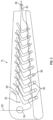
- FIG. 2 illustrates a portion of the high pressure turbine (HPT) 54.
- FIG. 2 also illustrates a high pressure turbine stage vanes 70 one of which (e.g., a first stage vane 71) is located forward of a first one of a pair of turbine disks 72 each having a plurality of turbine blades 74 secured thereto.
- the turbine blades 74 rotate proximate to blade outer air seals (BOAS) 75 which are located aft of the first stage vane 71.
- BOAS blade outer air seals
- the other vane 70 is located between the pair of turbine disks 72. This vane 70 may be referred to as the second stage vane 73.
- the first stage vane 71 is the first vane of the high pressure turbine section 54 that is located aft of the combustor section 26 and the second stage vane 73 is located aft of the first stage vane 71 and is located between the pair of turbine disks 72.
- blade outer air seals (BOAS) 75 are disposed between the first stage vane 71 and the second stage vane 73.
- the high pressure turbine stage vanes 70 e.g., first stage vane 71 or second stage vane 73
- the high pressure turbine (HPT) is subjected to gas temperatures well above the yield capability of its material.
- a supply of cooling air is applied to an internal cavity of components located in the hot sections of the gas turbine engine.
- This cooling air may also be used for surface film-cooling by supplying the cooling air through cooling holes drilled on the components.
- FIG. 3 schematically illustrates a blade outer air seal (BOAS) 75.
- Cooling air flow is illustrated by arrows 80 that is introduced into a cavity or channel 82 of the blade outer air seal 75 via at least one inlet opening 84.
- the cooling air flow is directed through the channels 82 that extend internally in the blade outer air seal 75.
- the channels 82 are provided with trip strips 86. These trip strips 86 can be generally referred to as protrusions or cooling features that extend from a surface of the channel.
- the trip strips create turbulences in the cooling air flow which enhances convection.
- the channel 82 is in fluid communication with the at least one inlet opening 84 and at least one outlet opening 88.
- the cooling air exiting the at least one outlet opening 88 may be used for surface film cooling.
- the at least one outlet opening 88 may be located away from the at least one inlet opening 84 such that maximum cooling efficiently can be achieved internally before the cooling air exits the channel 82 via the at least one outlet opening 88.
- prior manufacturing techniques have limited the size and detail in which the trip strips 86 can be produced.
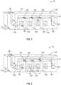
- FIG. 4 is an exploded view of the component.
- the component is a blade outer air seal 75.
- the blade outer air seal is formed from a bottom core 90, a top core 92 and an outboard face 94.
- the outboard face 94 has a plurality of inlet openings 96 that are in fluid communication with a plurality of channels or channel 98 formed in the bottom core 90.
- the inlet openings 96 are in fluid communication with the plurality of channels 98 via openings 100.
- the plurality of channels 98 comprising a plurality of pedestals 102 for increased heat transfer.
- Some of the pedestals 102 are provided with film cooling holes 104 that extend to an outer surface 106 of the bottom core 90.
- the film cooling holes 104 also extend to an interior channel 108 formed between the top core 92 the outboard face 94.
- cooling holes 110 are also formed in the blade outer air seal 75 that extend from the interior channel 108 to an outer end surface 112 of the blade outer air seal 75.
- Air flow through the blade outer air seal 75 is illustrated by the arrows in FIG. 6 .
- cooling air is directed from an outboard air supply to the channels 98 in the bottom core 90 where it contacts the pedestals 102 to transfer heat from the outer surface 106 to the cooling air.
- the heated air flows to the interior channel 108 through openings 114.
- This heated air is then cooled by outboard surface 116 which is exposed to cooler temperatures than the outer surface 106. This cools the air before it passes into openings 104 and 110.
- the outboard surface 116 of the outboard face 94 is radially further from the axis A of the engine 20 than surface 106 when the component is installed in the engine 20.
- openings 96 and 100 are located on an opposite end of the blade outer air seal with respect to openings 114 such that the air must travel across an entire length of the blade outer air seal before entering openings 104.
- the height (illustrated by arrows 120) of the cavities defined by the cores may vary.
- the size of the openings 104 may vary as well as the size of the pedestals 102 may vary. This is illustrated by arrows 122 and 124.
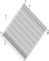
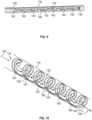
- FIGS. 8-10 an alternative embodiment of the present disclosure is illustrated.
- a core 130 is illustrated for forming a component with a plurality of spiral channels 132.
- a desired material is cast into or around the production mold to product the part and then the core is removed.
- Each spiral channel 132 of the subsequently formed component has an inlet opening 134 and an outlet opening 136.
- the core 130 may be used to form a blade outer air seal 75 or any other component of the gas turbine engine 20 that requires cooling via cooling air.
- the cooling air exiting the outlet opening 136 may also be used for may be used for surface film cooling.
- the blade outer air seal 75 may comprise a single spiral channel 132 or a plurality of spiral channels 132.
- cooling air is directed into a spiral geometry that circulates air from a hotter lower surface (e.g., surface 106 illustrated in at least FIGS. 5-7 and 9 namely, a surface that is radially closer to the engine axis A than surface 116 when the component is installed into the engine 20) to an upper cooler surface (e.g., surface 116 illustrated in at least FIGS. 5-7 and 9 namely, a surface that is radially further from the engine axis A than surface 106 when the component is installed into the engine 20).
- a hotter lower surface e.g., surface 106 illustrated in at least FIGS. 5-7 and 9 namely, a surface that is radially closer to the engine axis A than surface 116 when the component is installed into the engine 20
- an upper cooler surface e.g., surface 116 illustrated in at least FIGS. 5-7 and 9 namely, a surface that is radially further from the engine axis A than surface 106 when the component is installed into the engine 20.
- FIG. 9 is a cross sectional view of one of the spiral channels 132 formed from the core 130 illustrated in FIG. 8 . As illustrated and after the component is formed about the core 130 and the core 130 is subsequently removed, a spiral wall 138 is formed and extends generally from the inlet opening 134 to the outlet opening 136. In other words, FIG. 9 is a cross sectional view of a portion of a component formed from the core 130.
- FIG. 10 is a perspective view of one of the spiral walls 138 corresponding to one of the spiral channels 132 formed from the core 130. Air flow through the spiral channel 132 is illustrated by arrows 140. The inlet opening 136, the outlet opening 134, upper surface or cooler surface 116 and the lower surface or hotter surface 106 of the component are also illustrated in at least FIG. 10 .
- a blade outer air seal is illustrated as the component, the component may be any component that requires cooling including but not limited to anyone of the following: blade outer air seals (BOAS), vanes, blades and other components that are required to be cooled by a source of cooling air.
- BOAS blade outer air seals
Landscapes
- Engineering & Computer Science (AREA)
- Mechanical Engineering (AREA)
- General Engineering & Computer Science (AREA)
- Turbine Rotor Nozzle Sealing (AREA)
Abstract
Description
- This disclosure relates to cooling features for a component of gas turbine engine and more particularly, a component of a gas turbine engine with the aforementioned cooling features.
- Gas turbine engines typically include a compressor section, a combustor section and a turbine section. During operation, air is pressurized in the compressor section and is mixed with fuel and burned in the combustor section to generate hot combustion gases. The hot combustion gases are communicated through the turbine section, which extracts energy from the hot combustion gases to power the compressor section and other gas turbine engine loads.
- Both the compressor and turbine sections may include alternating series of rotating blades and stationary vanes that extend into the core flow path of the gas turbine engine. For example, in the turbine section, turbine blades rotate and extract energy from the hot combustion gases that are communicated along the core flow path of the gas turbine engine. The turbine vanes, which generally do not rotate, guide the airflow and prepare it for the next set of blades.
- Blade outer air seals (BOAS), vanes, blades and other components are located in hot sections of the gas turbine engine. In some instances these components are cooled with cooling air that passes through an interior cavity of the component. Accordingly, it is desirable to provide a cooled hot section component with features that improves the cooling efficiency.
- In a first aspect, there is provided a component for a gas turbine engine, including: at least one internal channel extending through a first portion of the component, the at least one internal channel extending through the first portion of the component having at least one inlet opening and at least one outlet opening each being in fluid communication with the at least one internal channel extending through the first portion of the component; a plurality of cooling features extending from a surface of the at least one internal channel extending through the first portion of the component; and at least one internal channel extending through a second portion of the component, the at least one internal channel extending through the second portion of the component is in fluid communication with the at least one internal channel extending through the first portion of the component, the second portion being located on top of the first portion, the at least one internal channel extending through the second portion of the component having a plurality of openings extending from the least one internal channel extending through the second portion of the component through the plurality of cooling features to an outer surface of the component.
- In an embodiment of the foregoing embodiment, the component is a blade outer air seal.
- In a further embodiment of any of the foregoing embodiments, the blade outer air seal is formed from a bottom core, a top core and an outboard face, the outboard face defining the least one inlet opening and the bottom core defining the at least one internal channel extending through the first portion of the component.
- In a further embodiment of any of the foregoing embodiments, the bottom core defines the plurality of cooling features.
- In a further embodiment of any of the foregoing embodiments, the plurality of cooling features are pedestals.
- In a further embodiment of any of the foregoing embodiments, the least one internal channel extending through the first portion of the component is a plurality of internal channels and the at least one internal channel extending through the second portion of the component is a plurality of internal channels.
- In a further embodiment of any of the foregoing embodiments, a plurality of cooling holes extend from the at least one internal channel extending through the second portion of the component to an outer end surface of the blade outer air seal.
- In another aspect, there is provided a component for a gas turbine engine, including: at least one internal channel extending through the component, the at least one internal channel having an inlet opening and an outlet opening each being in fluid communication with the at least one internal channel, the at least one internal channel having a spiral configuration extending from the inlet opening to the outlet opening.
- In a further embodiment of any of the foregoing embodiments, the component is a blade outer air seal.
- In a further embodiment of any of the foregoing embodiments, the least one internal channel is a plurality of internal channels.
- In another aspect, there is provided a gas turbine engine, including; a component configured to receive a cooling air flow, the component including at least one internal channel extending through a first portion of the component, the at least one internal channel extending through the first portion of the component having at least one inlet opening and at least one outlet opening each being in fluid communication with the at least one internal channel extending through the first portion of the component; a plurality of cooling features extending from a surface of the at least one internal channel; and at least one internal channel extending through a second portion of the component, the at least one internal channel extending through the second portion of the component is in fluid communication with the at least one internal channel extending through the first portion of the component, the second portion being located on top of the first portion, the at least one internal channel extending through the second portion of the component having a plurality of openings extending from the least one internal channel extending through the second portion of the component through the plurality of cooling features to an outer surface of the component.
- In a further embodiment of any of the foregoing embodiments, the component is a blade outer air seal.
- In a further embodiment of any of the foregoing embodiments, the blade outer air seal is formed from a bottom core, a top core and an outboard face, the outboard face defining the least one inlet opening and the bottom core defining the at least one internal channel extending through the first portion of the component.
- In a further embodiment of any of the foregoing embodiments, the bottom core defines the plurality of cooling features.
- In a further embodiment of any of the foregoing embodiments, the plurality of cooling features are pedestals.
- In a further embodiment of any of the foregoing embodiments, the least one internal channel extending through the first portion of the component is a plurality of internal channels and the at least one internal channel extending through the second portion of the component is a plurality of internal channels.
- In a further embodiment of any of the foregoing embodiments, a plurality of cooling holes extend from the at least one internal channel extending through the second portion of the component to an outer end surface of the blade outer air seal.
- The following descriptions should not be considered limiting in any way. With reference to the accompanying drawings, like elements are numbered alike:
-
FIG. 1 is a schematic, partial cross-sectional view of a gas turbine engine in accordance with this disclosure; -
FIG. 2 is a schematic view of a two-stage high pressure turbine of the gas turbine engine; -
FIG. 3 is a schematic view of a blade outer air seal for use in a gas turbine engine; -
FIG. 4 is an exploded view of a component formed in accordance with the present disclosure; -
FIGS. 5-7 are cross-sectional views of a component formed in accordance with the present disclosure; -
FIG. 8 is a perspective view of a core for forming a component in accordance with the present disclosure; -
FIG. 9 is a cross-sectional view of a portion of a component formed from the core illustrated inFIG. 8 ; and -
FIG. 10 is a perspective view illustrating air flow through the portion of the component illustrated inFIG. 9 . - A detailed description of one or more embodiments of the disclosed apparatus and method are presented herein by way of exemplification and not limitation with reference to the FIGS.
-
FIG. 1 schematically illustrates agas turbine engine 20. Thegas turbine engine 20 is disclosed herein as a two-spool turbofan that generally incorporates afan section 22, acompressor section 24, acombustor section 26 and aturbine section 28. Alternative engines might include other systems or features. Thefan section 22 drives air along a bypass flow path B in a bypass duct, while thecompressor section 24 drives air along a core flow path C1 for compression and communication into thecombustor section 26 then expansion through theturbine section 28. Although depicted as a two-spool turbofan gas turbine engine in the disclosed non-limiting embodiment, it should be understood that the concepts described herein are not limited to use with two-spool turbofans as the teachings may be applied to other types of turbine engines including three-spool architectures. - The
exemplary engine 20 generally includes alow speed spool 30 and ahigh speed spool 32 mounted for rotation about an engine central longitudinal axis A relative to an enginestatic structure 36 viaseveral bearing systems 38. It should be understood thatvarious bearing systems 38 at various locations may alternatively or additionally be provided, and the location ofbearing systems 38 may be varied as appropriate to the application. - The
low speed spool 30 generally includes aninner shaft 40 that interconnects afan 42, a first orlow pressure compressor 44 and a first orlow pressure turbine 46. Theinner shaft 40 is connected to thefan 42 through a speed change mechanism, which in exemplarygas turbine engine 20 is illustrated as a gearedarchitecture 48 to drive thefan 42 at a lower speed than thelow speed spool 30. Thehigh speed spool 32 includes anouter shaft 50 that interconnects a second orhigh pressure compressor 52 and a second orhigh pressure turbine 54. Acombustor 56 is arranged inexemplary gas turbine 20 between thehigh pressure compressor 52 and thehigh pressure turbine 54. Amid-turbine frame 57 of the enginestatic structure 36 is arranged generally between thehigh pressure turbine 54 and thelow pressure turbine 46. Themid-turbine frame 57 further supports bearingsystems 38 in theturbine section 28. Theinner shaft 40 and theouter shaft 50 are concentric and rotate viabearing systems 38 about the engine central longitudinal axis A which is collinear with their longitudinal axes. - The core airflow is compressed by the
low pressure compressor 44 then thehigh pressure compressor 52, mixed and burned with fuel in thecombustor 56, then expanded over thehigh pressure turbine 54 andlow pressure turbine 46. Themid-turbine frame 57 includesairfoils 59 which are in the core airflow path C. Theturbines low speed spool 30 andhigh speed spool 32 in response to the expansion. It will be appreciated that each of the positions of thefan section 22,compressor section 24,combustor section 26,turbine section 28, and fandrive gear system 48 may be varied. For example,gear system 48 may be located aft ofcombustor section 26 or even aft ofturbine section 28, andfan section 22 may be positioned forward or aft of the location ofgear system 48. - The
engine 20 in one example is a high-bypass geared aircraft engine. In a further example, theengine 20 bypass ratio is greater than about six (6), with an example embodiment being greater than about ten (10), the gearedarchitecture 48 is an epicyclic gear train, such as a planetary gear system or other gear system, with a gear reduction ratio of greater than about 2.3 and thelow pressure turbine 46 has a pressure ratio that is greater than about five. In one disclosed embodiment, theengine 20 bypass ratio is greater than about ten (10:1), the fan diameter is significantly larger than that of thelow pressure compressor 44, and thelow pressure turbine 46 has a pressure ratio that is greater than about five (5:1).Low pressure turbine 46 pressure ratio is pressure measured prior to inlet oflow pressure turbine 46 as related to the pressure at the outlet of thelow pressure turbine 46 prior to an exhaust nozzle. The gearedarchitecture 48 may be an epicycle gear train, such as a planetary gear system or other gear system, with a gear reduction ratio of greater than about 2.3:1. It should be understood, however, that the above parameters are only exemplary of one embodiment of a geared architecture engine and that the present disclosure is applicable to other gas turbine engines including direct drive turbofans. - A significant amount of thrust is provided by the bypass flow B due to the high bypass ratio. The
fan section 22 of theengine 20 is designed for a particular flight condition--typically cruise at about 0.8 Mach and about 35,000 feet (10,688 meters). The flight condition of 0.8 Mach and 35,000 ft (10,688 meters), with the engine at its best fuel consumption--also known as "bucket cruise Thrust Specific Fuel Consumption ('TSFC')"--is the industry standard parameter of pound-mass (lbm) of fuel per hour being burned divided by pound-force (lbf) of thrust the engine produces at that minimum point. "Low fan pressure ratio" is the pressure ratio across the fan blade alone, without a Fan Exit Guide Vane ("FEGV") system. The low fan pressure ratio as disclosed herein according to one non-limiting embodiment is less than about 1.45. "Low corrected fan tip speed" is the actual fan tip speed in ft/sec divided by an industry standard temperature correction of [(Tram °R)/(518.7 °R)]0.5 (where °R = K x 9/5). The "Low corrected fan tip speed" as disclosed herein according to one non-limiting embodiment is less than about 1150 ft/second (350.5 m/sec). - In a further example, the
fan 42 includes less than about 26 fan blades. In another non-limiting embodiment, thefan 42 includes less than about 20 fan blades. Moreover, in one further embodiment thelow pressure turbine 46 includes no more than about 6 turbine rotors schematically indicated at 46a. In a further non-limiting example thelow pressure turbine 46 includes about 3 turbine rotors. A ratio between the number of blades of thefan 42 and the number of lowpressure turbine rotors 46a is between about 3.3 and about 8.6. The examplelow pressure turbine 46 provides the driving power to rotate thefan section 22 and therefore the relationship between the number ofturbine rotors 46a in thelow pressure turbine 46 and the number of blades in thefan section 22 discloses an examplegas turbine engine 20 with increased power transfer efficiency. -
FIG. 2 illustrates a portion of the high pressure turbine (HPT) 54.FIG. 2 also illustrates a high pressureturbine stage vanes 70 one of which (e.g., a first stage vane 71) is located forward of a first one of a pair ofturbine disks 72 each having a plurality ofturbine blades 74 secured thereto. Theturbine blades 74 rotate proximate to blade outer air seals (BOAS) 75 which are located aft of thefirst stage vane 71. Theother vane 70 is located between the pair ofturbine disks 72. Thisvane 70 may be referred to as the second stage vane 73. As used herein thefirst stage vane 71 is the first vane of the highpressure turbine section 54 that is located aft of thecombustor section 26 and the second stage vane 73 is located aft of thefirst stage vane 71 and is located between the pair ofturbine disks 72. In addition, blade outer air seals (BOAS) 75 are disposed between thefirst stage vane 71 and the second stage vane 73. The high pressure turbine stage vanes 70 (e.g.,first stage vane 71 or second stage vane 73) are one of a plurality ofvanes 70 that are positioned circumferentially about the axis A of the engine in order to provide astator assembly 76. Hot gases from thecombustor section 26 flow through the turbine in the direction of arrow 77. Although a two-stage high pressure turbine is illustrated other high pressure turbines are considered to be within the scope of various embodiments of the present disclosure. - The high pressure turbine (HPT) is subjected to gas temperatures well above the yield capability of its material. In order to mitigate such high temperature detrimental effects, a supply of cooling air is applied to an internal cavity of components located in the hot sections of the gas turbine engine. This cooling air may also be used for surface film-cooling by supplying the cooling air through cooling holes drilled on the components.
-
FIG. 3 schematically illustrates a blade outer air seal (BOAS) 75. Cooling air flow is illustrated byarrows 80 that is introduced into a cavity orchannel 82 of the bladeouter air seal 75 via at least oneinlet opening 84. The cooling air flow is directed through thechannels 82 that extend internally in the bladeouter air seal 75. Thechannels 82 are provided with trip strips 86. These trip strips 86 can be generally referred to as protrusions or cooling features that extend from a surface of the channel. The trip strips create turbulences in the cooling air flow which enhances convection. Thechannel 82 is in fluid communication with the at least oneinlet opening 84 and at least oneoutlet opening 88. The cooling air exiting the at least oneoutlet opening 88 may be used for surface film cooling. The at least oneoutlet opening 88 may be located away from the at least oneinlet opening 84 such that maximum cooling efficiently can be achieved internally before the cooling air exits thechannel 82 via the at least oneoutlet opening 88. However prior manufacturing techniques have limited the size and detail in which the trip strips 86 can be produced. - In accordance with the present disclosure tools and/or cores with highly complex three-dimensional features are contemplated where components are formed with features for providing enhanced cooling.
- For example and referring now to at least
FIGS. 4-7 views of a component formed in accordance with the present disclosure is illustrated.FIG. 4 is an exploded view of the component. - In accordance with an exemplary embodiment of the present disclosure the component is a blade
outer air seal 75. As illustrated in at leastFIGS. 4-7 , the blade outer air seal is formed from abottom core 90, atop core 92 and anoutboard face 94. Theoutboard face 94 has a plurality ofinlet openings 96 that are in fluid communication with a plurality of channels orchannel 98 formed in thebottom core 90. Theinlet openings 96 are in fluid communication with the plurality ofchannels 98 viaopenings 100. - The plurality of
channels 98 comprising a plurality ofpedestals 102 for increased heat transfer. Some of thepedestals 102 are provided with film cooling holes 104 that extend to anouter surface 106 of thebottom core 90. The film cooling holes 104 also extend to aninterior channel 108 formed between thetop core 92 theoutboard face 94. - In addition, cooling holes 110 are also formed in the blade
outer air seal 75 that extend from theinterior channel 108 to anouter end surface 112 of the bladeouter air seal 75. - Air flow through the blade
outer air seal 75 is illustrated by the arrows inFIG. 6 . As such, cooling air is directed from an outboard air supply to thechannels 98 in thebottom core 90 where it contacts thepedestals 102 to transfer heat from theouter surface 106 to the cooling air. Then the heated air flows to theinterior channel 108 throughopenings 114. This heated air is then cooled byoutboard surface 116 which is exposed to cooler temperatures than theouter surface 106. This cools the air before it passes intoopenings openings surfaces outboard surface 116 of theoutboard face 94 is radially further from the axis A of theengine 20 thansurface 106 when the component is installed in theengine 20. - As illustrated,
openings openings 114 such that the air must travel across an entire length of the blade outer air seal before enteringopenings 104. - As illustrated in
FIG. 7 , the height (illustrated by arrows 120) of the cavities defined by the cores may vary. In addition, the size of theopenings 104 may vary as well as the size of thepedestals 102 may vary. This is illustrated byarrows 122 and 124. - Referring now to
FIGS. 8-10 , an alternative embodiment of the present disclosure is illustrated. InFIG. 8 , acore 130 is illustrated for forming a component with a plurality ofspiral channels 132. As mentioned above a desired material is cast into or around the production mold to product the part and then the core is removed. Eachspiral channel 132 of the subsequently formed component has aninlet opening 134 and anoutlet opening 136. Similar to the previous embodiment, thecore 130 may be used to form a bladeouter air seal 75 or any other component of thegas turbine engine 20 that requires cooling via cooling air. In addition and as mentioned above, the cooling air exiting theoutlet opening 136 may also be used for may be used for surface film cooling. Here the bladeouter air seal 75 may comprise asingle spiral channel 132 or a plurality ofspiral channels 132. - Here the cooling air is directed into a spiral geometry that circulates air from a hotter lower surface (e.g.,
surface 106 illustrated in at leastFIGS. 5-7 and9 namely, a surface that is radially closer to the engine axis A thansurface 116 when the component is installed into the engine 20) to an upper cooler surface (e.g.,surface 116 illustrated in at leastFIGS. 5-7 and9 namely, a surface that is radially further from the engine axis A thansurface 106 when the component is installed into the engine 20). The cooling air flow is depicted inFIGS. 9 and 10 . -
FIG. 9 is a cross sectional view of one of thespiral channels 132 formed from thecore 130 illustrated inFIG. 8 . As illustrated and after the component is formed about thecore 130 and thecore 130 is subsequently removed, aspiral wall 138 is formed and extends generally from the inlet opening 134 to theoutlet opening 136. In other words,FIG. 9 is a cross sectional view of a portion of a component formed from thecore 130. -
FIG. 10 is a perspective view of one of thespiral walls 138 corresponding to one of thespiral channels 132 formed from thecore 130. Air flow through thespiral channel 132 is illustrated byarrows 140. Theinlet opening 136, theoutlet opening 134, upper surface orcooler surface 116 and the lower surface orhotter surface 106 of the component are also illustrated in at leastFIG. 10 . - Although a blade outer air seal is illustrated as the component, the component may be any component that requires cooling including but not limited to anyone of the following: blade outer air seals (BOAS), vanes, blades and other components that are required to be cooled by a source of cooling air.
- The term "about" is intended to include the degree of error associated with measurement of the particular quantity based upon the equipment available at the time of filing the application. For example, "about" can include a range of ± 8% or 5%, or 2% of a given value.
- The terminology used herein is for the purpose of describing particular embodiments only and is not intended to be limiting of the present disclosure. As used herein, the singular forms "a", "an" and "the" are intended to include the plural forms as well, unless the context clearly indicates otherwise. It will be further understood that the terms "comprises" and/or "comprising," when used in this specification, specify the presence of stated features, integers, steps, operations, elements, and/or components, but do not preclude the presence or addition of one or more other features, integers, steps, operations, element components, and/or groups thereof.
- While the present disclosure has been described with reference to an exemplary embodiment or embodiments, it will be understood by those skilled in the art that various changes may be made and equivalents may be substituted for elements thereof without departing from the scope of the present disclosure. In addition, many modifications may be made to adapt a particular situation or material to the teachings of the present disclosure without departing from the essential scope thereof. Therefore, it is intended that the present disclosure not be limited to the particular embodiment disclosed as the best mode contemplated for carrying out this present disclosure, but that the present disclosure will include all embodiments falling within the scope of the claims.
Claims (11)
- A component (75) for a gas turbine engine (20), comprising:at least one internal channel (98) extending through a first portion of the component (75), the at least one internal channel (98) having at least one inlet opening (96) and at least one outlet opening (114) each being in fluid communication with the at least one internal channel (98) extending through the first portion of the component (75);a plurality of cooling features (102) extending from a surface of the at least one internal channel (98) extending through the first portion of the component (75); andat least one internal channel (108) extending through a second portion of the component (75), the at least one internal channel (108) extending through the second portion of the component (75) is in fluid communication with the at least one internal channel (98) extending through the first portion of the component (75), the second portion being located on top of the first portion, the at least one internal channel (108) extending through the second portion of the component (75) having a plurality of openings (104) extending from the least one internal channel (108) extending through the second portion of the component (75) through the plurality of cooling features (102) to an outer surface (106) of the component (75).
- The component (75) according to claim 1, wherein the component (75) is a blade outer air seal.
- The component (75) according to claim 2, wherein the blade outer air seal is formed from a bottom core (90), a top core (92) and an outboard face (94), the outboard face (94) defining the least one inlet opening (96) and the bottom core (90) defining the at least one internal channel (98) extending through the first portion of the component (75).
- The component (75) according to claim 3, wherein the bottom core (90) defines the plurality of cooling features (102).
- The component (75) according to claim 2, 3 or 4, wherein a plurality of cooling holes (110) extend from the at least one internal channel (108) extending through the second portion of the component (75) to an outer end surface (112) of the blade outer air seal (75).
- The component (75) according to any preceding claim, wherein the plurality of cooling features (102) are pedestals.
- The component (75) according to any preceding claim, wherein the least one internal channel (98) extending through the first portion of the component (75) is a plurality of internal channels and the at least one internal channel (108) extending through the second portion of the component (75) is a plurality of internal channels.
- A component (75) for a gas turbine engine (20), comprising:
at least one internal channel (132) extending through the component (75), the at least one internal channel (132) having an inlet opening (134) and an outlet opening (136) each being in fluid communication with the at least one internal channel (132), the at least one internal channel (132) having a spiral configuration extending from the inlet opening (134) to the outlet opening (136). - The component (75) according to claim 8, wherein the component (75) is a blade outer air seal.
- The component (75) according to claim 8 or 9, wherein the least one internal channel (132) is a plurality of internal channels.
- A gas turbine engine (20), comprising:
the component (75) of any of claims 1 to 7 configured to receive a cooling air flow.
Applications Claiming Priority (1)
| Application Number | Priority Date | Filing Date | Title |
|---|---|---|---|
| US17/965,311 US20240125243A1 (en) | 2022-10-13 | 2022-10-13 | Cooling features for a component of a gas turbine engine |
Publications (2)
| Publication Number | Publication Date |
|---|---|
| EP4353950A2 true EP4353950A2 (en) | 2024-04-17 |
| EP4353950A3 EP4353950A3 (en) | 2024-06-12 |
Family
ID=88412090
Family Applications (1)
| Application Number | Title | Priority Date | Filing Date |
|---|---|---|---|
| EP23203246.6A Pending EP4353950A3 (en) | 2022-10-13 | 2023-10-12 | Blade outer air seal with cooling channels |
Country Status (2)
| Country | Link |
|---|---|
| US (1) | US20240125243A1 (en) |
| EP (1) | EP4353950A3 (en) |
Family Cites Families (9)
| Publication number | Priority date | Publication date | Assignee | Title |
|---|---|---|---|---|
| US8292582B1 (en) * | 2009-07-09 | 2012-10-23 | Florida Turbine Technologies, Inc. | Turbine blade with serpentine flow cooling |
| WO2015065718A1 (en) * | 2013-10-30 | 2015-05-07 | United Technologies Corporation | Bore-cooled film dispensing pedestals |
| US10502066B2 (en) * | 2015-05-08 | 2019-12-10 | United Technologies Corporation | Turbine engine component including an axially aligned skin core passage interrupted by a pedestal |
| RU2706211C2 (en) * | 2016-01-25 | 2019-11-14 | Ансалдо Энерджиа Свитзерлэнд Аг | Cooled wall of turbine component and cooling method of this wall |
| US10577944B2 (en) * | 2017-08-03 | 2020-03-03 | General Electric Company | Engine component with hollow turbulators |
| US10533454B2 (en) * | 2017-12-13 | 2020-01-14 | Pratt & Whitney Canada Corp. | Turbine shroud cooling |
| US10794206B2 (en) * | 2018-09-05 | 2020-10-06 | Raytheon Technologies Corporation | CMC BOAS intersegment seal |
| US10634010B2 (en) * | 2018-09-05 | 2020-04-28 | United Technologies Corporation | CMC BOAS axial retaining clip |
| CN112855285B (en) * | 2019-11-28 | 2023-03-24 | 中国航发商用航空发动机有限责任公司 | Turbine blade and aircraft engine |
-
2022
- 2022-10-13 US US17/965,311 patent/US20240125243A1/en active Pending
-
2023
- 2023-10-12 EP EP23203246.6A patent/EP4353950A3/en active Pending
Also Published As
| Publication number | Publication date |
|---|---|
| US20240125243A1 (en) | 2024-04-18 |
| EP4353950A3 (en) | 2024-06-12 |
Similar Documents
| Publication | Publication Date | Title |
|---|---|---|
| US10920601B2 (en) | Blade outer air seal fin cooling assembly and method | |
| EP3536903B1 (en) | Cooling passage with structural rib and film cooling slot | |
| EP3514331A1 (en) | Cooled airfoil and corresponding gas turbine engine | |
| EP3561229A1 (en) | Gas turbine engine component with platform cover plate | |
| EP3502420B1 (en) | Component for a gas turbine engine and corresponding gas turbine engine | |
| US11828193B2 (en) | Vane core assemblies and methods | |
| EP4353951A1 (en) | Cooling features for a component of a gas turbine engine | |
| EP3564485B1 (en) | Airfoils, cores, and methods of manufacture for forming airfoils having fluidly connected platform cooling circuits | |
| EP4353950A2 (en) | Blade outer air seal with cooling channels | |
| US11168571B2 (en) | Airfoil having dead-end tip flag cavity | |
| US10815794B2 (en) | Baffle for components of gas turbine engines | |
| US20250369367A1 (en) | Cooling features for a component of a gas turbine engine | |
| US10961862B2 (en) | Fatigue resistant blade outer air seal | |
| EP3708776A1 (en) | Gasturbine airfoils having tapered tip flag cavity and cores for forming the same | |
| US12215601B2 (en) | Air foil with staggered cooling hole configuration | |
| EP4656840A1 (en) | Component for a gas turbine engine and gas turbine engine | |
| US10753210B2 (en) | Airfoil having improved cooling scheme | |
| US11434770B2 (en) | Tip cooling design | |
| EP3581762A2 (en) | Platform cooling arrangement for a gas turbine engine | |
| US20190309631A1 (en) | Airfoil having leading edge cooling scheme with backstrike compensation |
Legal Events
| Date | Code | Title | Description |
|---|---|---|---|
| PUAI | Public reference made under article 153(3) epc to a published international application that has entered the european phase |
Free format text: ORIGINAL CODE: 0009012 |
|
| STAA | Information on the status of an ep patent application or granted ep patent |
Free format text: STATUS: THE APPLICATION HAS BEEN PUBLISHED |
|
| AK | Designated contracting states |
Kind code of ref document: A2 Designated state(s): AL AT BE BG CH CY CZ DE DK EE ES FI FR GB GR HR HU IE IS IT LI LT LU LV MC ME MK MT NL NO PL PT RO RS SE SI SK SM TR |
|
| PUAL | Search report despatched |
Free format text: ORIGINAL CODE: 0009013 |
|
| AK | Designated contracting states |
Kind code of ref document: A3 Designated state(s): AL AT BE BG CH CY CZ DE DK EE ES FI FR GB GR HR HU IE IS IT LI LT LU LV MC ME MK MT NL NO PL PT RO RS SE SI SK SM TR |
|
| RIC1 | Information provided on ipc code assigned before grant |
Ipc: F01D 11/08 20060101ALI20240508BHEP Ipc: F01D 5/18 20060101AFI20240508BHEP |
|
| STAA | Information on the status of an ep patent application or granted ep patent |
Free format text: STATUS: REQUEST FOR EXAMINATION WAS MADE |
|
| 17P | Request for examination filed |
Effective date: 20241212 |