EP4353949A1 - Gas turbine engine vane and spar combination with variable air flow path - Google Patents
Gas turbine engine vane and spar combination with variable air flow path Download PDFInfo
- Publication number
- EP4353949A1 EP4353949A1 EP23202830.8A EP23202830A EP4353949A1 EP 4353949 A1 EP4353949 A1 EP 4353949A1 EP 23202830 A EP23202830 A EP 23202830A EP 4353949 A1 EP4353949 A1 EP 4353949A1
- Authority
- EP
- European Patent Office
- Prior art keywords
- stator vane
- spar
- cooling air
- combination
- sectional area
- Prior art date
- Legal status (The legal status is an assumption and is not a legal conclusion. Google has not performed a legal analysis and makes no representation as to the accuracy of the status listed.)
- Granted
Links
Images



Classifications
-
- F—MECHANICAL ENGINEERING; LIGHTING; HEATING; WEAPONS; BLASTING
- F01—MACHINES OR ENGINES IN GENERAL; ENGINE PLANTS IN GENERAL; STEAM ENGINES
- F01D—NON-POSITIVE DISPLACEMENT MACHINES OR ENGINES, e.g. STEAM TURBINES
- F01D25/00—Component parts, details, or accessories, not provided for in, or of interest apart from, other groups
- F01D25/08—Cooling; Heating; Heat-insulation
- F01D25/12—Cooling
-
- F—MECHANICAL ENGINEERING; LIGHTING; HEATING; WEAPONS; BLASTING
- F01—MACHINES OR ENGINES IN GENERAL; ENGINE PLANTS IN GENERAL; STEAM ENGINES
- F01D—NON-POSITIVE DISPLACEMENT MACHINES OR ENGINES, e.g. STEAM TURBINES
- F01D5/00—Blades; Blade-carrying members; Heating, heat-insulating, cooling or antivibration means on the blades or the members
- F01D5/12—Blades
- F01D5/28—Selecting particular materials; Particular measures relating thereto; Measures against erosion or corrosion
- F01D5/284—Selection of ceramic materials
-
- F—MECHANICAL ENGINEERING; LIGHTING; HEATING; WEAPONS; BLASTING
- F01—MACHINES OR ENGINES IN GENERAL; ENGINE PLANTS IN GENERAL; STEAM ENGINES
- F01D—NON-POSITIVE DISPLACEMENT MACHINES OR ENGINES, e.g. STEAM TURBINES
- F01D5/00—Blades; Blade-carrying members; Heating, heat-insulating, cooling or antivibration means on the blades or the members
- F01D5/12—Blades
- F01D5/14—Form or construction
- F01D5/18—Hollow blades, i.e. blades with cooling or heating channels or cavities; Heating, heat-insulating or cooling means on blades
- F01D5/186—Film cooling
-
- F—MECHANICAL ENGINEERING; LIGHTING; HEATING; WEAPONS; BLASTING
- F01—MACHINES OR ENGINES IN GENERAL; ENGINE PLANTS IN GENERAL; STEAM ENGINES
- F01D—NON-POSITIVE DISPLACEMENT MACHINES OR ENGINES, e.g. STEAM TURBINES
- F01D5/00—Blades; Blade-carrying members; Heating, heat-insulating, cooling or antivibration means on the blades or the members
- F01D5/12—Blades
- F01D5/14—Form or construction
- F01D5/18—Hollow blades, i.e. blades with cooling or heating channels or cavities; Heating, heat-insulating or cooling means on blades
- F01D5/187—Convection cooling
-
- F—MECHANICAL ENGINEERING; LIGHTING; HEATING; WEAPONS; BLASTING
- F01—MACHINES OR ENGINES IN GENERAL; ENGINE PLANTS IN GENERAL; STEAM ENGINES
- F01D—NON-POSITIVE DISPLACEMENT MACHINES OR ENGINES, e.g. STEAM TURBINES
- F01D5/00—Blades; Blade-carrying members; Heating, heat-insulating, cooling or antivibration means on the blades or the members
- F01D5/12—Blades
- F01D5/14—Form or construction
- F01D5/18—Hollow blades, i.e. blades with cooling or heating channels or cavities; Heating, heat-insulating or cooling means on blades
- F01D5/187—Convection cooling
- F01D5/188—Convection cooling with an insert in the blade cavity to guide the cooling fluid, e.g. forming a separation wall
-
- F—MECHANICAL ENGINEERING; LIGHTING; HEATING; WEAPONS; BLASTING
- F01—MACHINES OR ENGINES IN GENERAL; ENGINE PLANTS IN GENERAL; STEAM ENGINES
- F01D—NON-POSITIVE DISPLACEMENT MACHINES OR ENGINES, e.g. STEAM TURBINES
- F01D5/00—Blades; Blade-carrying members; Heating, heat-insulating, cooling or antivibration means on the blades or the members
- F01D5/12—Blades
- F01D5/14—Form or construction
- F01D5/18—Hollow blades, i.e. blades with cooling or heating channels or cavities; Heating, heat-insulating or cooling means on blades
- F01D5/187—Convection cooling
- F01D5/188—Convection cooling with an insert in the blade cavity to guide the cooling fluid, e.g. forming a separation wall
- F01D5/189—Convection cooling with an insert in the blade cavity to guide the cooling fluid, e.g. forming a separation wall the insert having a tubular cross-section, e.g. airfoil shape
-
- F—MECHANICAL ENGINEERING; LIGHTING; HEATING; WEAPONS; BLASTING
- F01—MACHINES OR ENGINES IN GENERAL; ENGINE PLANTS IN GENERAL; STEAM ENGINES
- F01D—NON-POSITIVE DISPLACEMENT MACHINES OR ENGINES, e.g. STEAM TURBINES
- F01D5/00—Blades; Blade-carrying members; Heating, heat-insulating, cooling or antivibration means on the blades or the members
- F01D5/12—Blades
- F01D5/28—Selecting particular materials; Particular measures relating thereto; Measures against erosion or corrosion
- F01D5/282—Selecting composite materials, e.g. blades with reinforcing filaments
-
- F—MECHANICAL ENGINEERING; LIGHTING; HEATING; WEAPONS; BLASTING
- F01—MACHINES OR ENGINES IN GENERAL; ENGINE PLANTS IN GENERAL; STEAM ENGINES
- F01D—NON-POSITIVE DISPLACEMENT MACHINES OR ENGINES, e.g. STEAM TURBINES
- F01D9/00—Stators
- F01D9/02—Nozzles; Nozzle boxes; Stator blades; Guide conduits, e.g. individual nozzles
- F01D9/04—Nozzles; Nozzle boxes; Stator blades; Guide conduits, e.g. individual nozzles forming ring or sector
- F01D9/041—Nozzles; Nozzle boxes; Stator blades; Guide conduits, e.g. individual nozzles forming ring or sector using blades
-
- F—MECHANICAL ENGINEERING; LIGHTING; HEATING; WEAPONS; BLASTING
- F01—MACHINES OR ENGINES IN GENERAL; ENGINE PLANTS IN GENERAL; STEAM ENGINES
- F01D—NON-POSITIVE DISPLACEMENT MACHINES OR ENGINES, e.g. STEAM TURBINES
- F01D9/00—Stators
- F01D9/06—Fluid supply conduits to nozzles or the like
- F01D9/065—Fluid supply or removal conduits traversing the working fluid flow, e.g. for lubrication-, cooling-, or sealing fluids
-
- F—MECHANICAL ENGINEERING; LIGHTING; HEATING; WEAPONS; BLASTING
- F05—INDEXING SCHEMES RELATING TO ENGINES OR PUMPS IN VARIOUS SUBCLASSES OF CLASSES F01-F04
- F05D—INDEXING SCHEME FOR ASPECTS RELATING TO NON-POSITIVE-DISPLACEMENT MACHINES OR ENGINES, GAS-TURBINES OR JET-PROPULSION PLANTS
- F05D2220/00—Application
- F05D2220/30—Application in turbines
- F05D2220/32—Application in turbines in gas turbines
-
- F—MECHANICAL ENGINEERING; LIGHTING; HEATING; WEAPONS; BLASTING
- F05—INDEXING SCHEMES RELATING TO ENGINES OR PUMPS IN VARIOUS SUBCLASSES OF CLASSES F01-F04
- F05D—INDEXING SCHEME FOR ASPECTS RELATING TO NON-POSITIVE-DISPLACEMENT MACHINES OR ENGINES, GAS-TURBINES OR JET-PROPULSION PLANTS
- F05D2240/00—Components
- F05D2240/10—Stators
- F05D2240/12—Fluid guiding means, e.g. vanes
-
- F—MECHANICAL ENGINEERING; LIGHTING; HEATING; WEAPONS; BLASTING
- F05—INDEXING SCHEMES RELATING TO ENGINES OR PUMPS IN VARIOUS SUBCLASSES OF CLASSES F01-F04
- F05D—INDEXING SCHEME FOR ASPECTS RELATING TO NON-POSITIVE-DISPLACEMENT MACHINES OR ENGINES, GAS-TURBINES OR JET-PROPULSION PLANTS
- F05D2260/00—Function
- F05D2260/20—Heat transfer, e.g. cooling
-
- F—MECHANICAL ENGINEERING; LIGHTING; HEATING; WEAPONS; BLASTING
- F05—INDEXING SCHEMES RELATING TO ENGINES OR PUMPS IN VARIOUS SUBCLASSES OF CLASSES F01-F04
- F05D—INDEXING SCHEME FOR ASPECTS RELATING TO NON-POSITIVE-DISPLACEMENT MACHINES OR ENGINES, GAS-TURBINES OR JET-PROPULSION PLANTS
- F05D2300/00—Materials; Properties thereof
- F05D2300/60—Properties or characteristics given to material by treatment or manufacturing
- F05D2300/603—Composites; e.g. fibre-reinforced
- F05D2300/6033—Ceramic matrix composites [CMC]
-
- Y—GENERAL TAGGING OF NEW TECHNOLOGICAL DEVELOPMENTS; GENERAL TAGGING OF CROSS-SECTIONAL TECHNOLOGIES SPANNING OVER SEVERAL SECTIONS OF THE IPC; TECHNICAL SUBJECTS COVERED BY FORMER USPC CROSS-REFERENCE ART COLLECTIONS [XRACs] AND DIGESTS
- Y02—TECHNOLOGIES OR APPLICATIONS FOR MITIGATION OR ADAPTATION AGAINST CLIMATE CHANGE
- Y02T—CLIMATE CHANGE MITIGATION TECHNOLOGIES RELATED TO TRANSPORTATION
- Y02T50/00—Aeronautics or air transport
- Y02T50/60—Efficient propulsion technologies, e.g. for aircraft
Definitions
- This application relates to a vane for use in a gas turbine engine which includes an internal spar, and defining a cooling air flow path with an inner surface of the vane.
- Gas turbine engines typically include a fan delivering air into a bypass duct as propulsion air. Air is also delivered into a compressor where it is compressed and delivered into a combustor. In the combustor the air is mixed with fuel and ignited. Products of this combustion pass downstream over turbine rotors, driving them to rotate. The turbine rotors drive the fan and compressor rotors.
- CMC ceramic matrix composites
- a CMC vane typically has an internal metal spar providing additional structural support.
- An outer surface of the spar defines a cooling air flow path in combination with an inner surface of a cooling channel in the CMC stator body.
- a gas turbine engine stator vane combination in an aspect of the present invention, includes a stator vane body having an airfoil with a leading edge, a trailing edge, a suction side and a pressure side, and having at least one internal cooling channel.
- the stator vane body is formed of ceramic matrix composite materials.
- a spar is received within the at least one cooling air channel and formed of a metal.
- the spar has an outer peripheral surface spaced from an inner peripheral surface of the cooling air channel to define a cooling air path, with the cooling air path having a varying cross-sectional area through the cooling air channel.
- stator vane body has platforms at each of two radial ends of the airfoil, and the spar extends through the cooling air channel and beyond each of the platforms.
- the spar has a leading (front) edge end, a trailing (aft) edge end, a suction wall face and a pressure wall face all associated with corresponding structure on the stator vane body.
- a first axial distance is defined between the front edge end and the aft edge end of the spar.
- a second axial distance is defined between the leading edge of the stator vane body and the trailing edge of the stator vane body and the first distance being between 10 and 90% of the second distance.
- variable cross-sectional area is achieved by the spar having a variation in the outer peripheral surface, with a thinner portion leading into an outwardly first ramped portion at each of the leading edge, the trailing edge, the suction wall face and the pressure wall face of the spar to change the cross-sectional area.
- the enlarged surface portions are formed on the inner peripheral surface of the stator vane body.
- the enlarged surface portions are formed on the outer peripheral surface of the spar.
- the enlarged surface portions have ramped portions leading from thinner portions into thicker portions to vary the cross-sectional area.
- the enlarged surface portions have discrete steps to change the cross-sectional area.
- the enlarged surface portions are formed on the inner surface of the stator vane body.
- the enlarged portions have ramped portions leading from thinner portions into thicker portions to vary the cross-sectional area.
- the enlarged portions have discrete steps to change the cross-sectional area.
- the enlarged surface portions are formed on the outer peripheral surface of the spar.
- the enlarged surface portions are formed on the inner surface of the stator vane body.
- a gas turbine engine in another aspect of the present invention, includes a compressor section, a combustor section and a turbine section.
- the turbine section has alternating rows of rotating turbine blades, and rows of stator vanes, with at least one row of the stator vanes being formed of ceramic matrix composite materials.
- the stator vanes have a stator vane body having an airfoil with a leading edge, a trailing edge, a suction side and a pressure side, and having at least one internal cooling channel.
- the stator vane body is formed of ceramic matrix composite materials.
- a spar is received within the at least one cooling air channel and formed of a metal.
- the spar has an outer peripheral surface spaced from an inner peripheral surface of the cooling air channel to define a cooling air path, with the cooling air path having a varying cross-sectional area through the cooling air channel.
- the spar has a leading edge end, a trailing edge end, a suction wall face and a pressure wall face all associated with corresponding structure on the stator vane body.
- a first axial distance is defined between the front edge and the aft edge end of the spar.
- a second axial distance is defined between the leading edge of the stator vane body and the trailing edge of the stator vane body and the first distance being between 10 and 90% of the second distance.
- variable cross-sectional area is achieved by the spar having a variation in the outer surface with there being a thinner portion leading into an outwardly ramped portion at each of the front edge, the aft edge, the suction wall face and the pressure wall face of the spar to change the cross-sectional area.
- the present disclosure may include any one or more of the individual features disclosed above and/or below alone or in any combination thereof.
- FIG. 1 schematically illustrates a gas turbine engine 20.
- the gas turbine engine 20 is disclosed herein as a two-spool turbofan that generally incorporates a fan section 22, a compressor section 24, a combustor section 26 and a turbine section 28.
- the fan section 22 may include a single-stage fan 42 having a plurality of fan blades 43.
- the fan blades 43 may have a fixed stagger angle or may have a variable pitch to direct incoming airflow from an engine inlet.
- the fan 42 drives air along a bypass flow path B in a bypass duct 13 defined within a housing 15 such as a fan case or nacelle, and also drives air along a core flow path C for compression and communication into the combustor section 26 then expansion through the turbine section 28.
- a splitter 29 aft of the fan 42 divides the air between the bypass flow path B and the core flow path C.
- the housing 15 may surround the fan 42 to establish an outer diameter of the bypass duct 13.
- the splitter 29 may establish an inner diameter of the bypass duct 13.
- the exemplary engine 20 generally includes a low speed spool 30 and a high speed spool 32 mounted for rotation about an engine central longitudinal axis A relative to an engine static structure 36 via several bearing systems 38. It should be understood that various bearing systems 38 at various locations may alternatively or additionally be provided, and the location of bearing systems 38 may be varied as appropriate to the application.
- the low speed spool 30 generally includes an inner shaft 40 that interconnects, a first (or low) pressure compressor 44 and a first (or low) pressure turbine 46.
- the inner shaft 40 is connected to the fan 42 through a speed change mechanism, which in the exemplary gas turbine engine 20 is illustrated as a geared architecture 48 to drive the fan 42 at a lower speed than the low speed spool 30.
- the inner shaft 40 may interconnect the low pressure compressor 44 and low pressure turbine 46 such that the low pressure compressor 44 and low pressure turbine 46 are rotatable at a common speed and in a common direction.
- the low pressure turbine 46 drives both the fan 42 and low pressure compressor 44 through the geared architecture 48 such that the fan 42 and low pressure compressor 44 are rotatable at a common speed.
- the high speed spool 32 includes an outer shaft 50 that interconnects a second (or high) pressure compressor 52 and a second (or high) pressure turbine 54.
- a combustor 56 is arranged in the exemplary gas turbine 20 between the high pressure compressor 52 and the high pressure turbine 54.
- a mid-turbine frame 57 of the engine static structure 36 may be arranged generally between the high pressure turbine 54 and the low pressure turbine 46.
- the mid-turbine frame 57 further supports bearing systems 38 in the turbine section 28.
- the inner shaft 40 and the outer shaft 50 are concentric and rotate via bearing systems 38 about the engine central longitudinal axis A which is collinear with their longitudinal axes.
- Airflow in the core flow path C is compressed by the low pressure compressor 44 then the high pressure compressor 52, mixed and burned with fuel in the combustor 56, then expanded through the high pressure turbine 54 and low pressure turbine 46.
- the mid-turbine frame 57 includes airfoils 59 which are in the core flow path C.
- the turbines 46, 54 rotationally drive the respective low speed spool 30 and high speed spool 32 in response to the expansion.
- gear system 48 may be located aft of the low pressure compressor, or aft of the combustor section 26 or even aft of turbine section 28, and fan 42 may be positioned forward or aft of the location of gear system 48.
- the low pressure compressor 44, high pressure compressor 52, high pressure turbine 54 and low pressure turbine 46 each include one or more stages having a row of rotatable airfoils. Each stage may include a row of vanes adjacent the rotatable airfoils.
- the rotatable airfoils are schematically indicated at 47, and the vanes are schematically indicated at 49.
- the engine 20 may be a high-bypass geared aircraft engine.
- the bypass ratio can be greater than or equal to 10.0 and less than or equal to about 18.0, or more narrowly can be less than or equal to 16.0.
- the geared architecture 48 may be an epicyclic gear train, such as a planetary gear system or a star gear system.
- the epicyclic gear train may include a sun gear, a ring gear, a plurality of intermediate gears meshing with the sun gear and ring gear, and a carrier that supports the intermediate gears.
- the sun gear may provide an input to the gear train.
- the ring gear (e.g., star gear system) or carrier (e.g., planetary gear system) may provide an output of the gear train to drive the fan 42.
- a gear reduction ratio may be greater than or equal to 2.3, or more narrowly greater than or equal to 3.0, and in some embodiments the gear reduction ratio is greater than or equal to 3.4.
- the gear reduction ratio may be less than or equal to 4.0.
- the fan diameter is significantly larger than that of the low pressure compressor 44.
- the low pressure turbine 46 can have a pressure ratio that is greater than or equal to 8.0 and in some embodiments is greater than or equal to 10.0.
- the low pressure turbine pressure ratio can be less than or equal to 13.0, or more narrowly less than or equal to 12.0.
- Low pressure turbine 46 pressure ratio is pressure measured prior to an inlet of low pressure turbine 46 as related to the pressure at the outlet of the low pressure turbine 46 prior to an exhaust nozzle. It should be understood, however, that the above parameters are only exemplary of one embodiment of a geared architecture engine and that the present invention is applicable to other gas turbine engines including direct drive turbofans. All of these parameters are measured at the cruise condition described below.
- the fan section 22 of the engine 20 is designed for a particular flight condition -- typically cruise at about 0.8 Mach and about 35,000 feet (10,668 meters).
- the flight condition of 0.8 Mach and 35,000 ft (10,668 meters), with the engine at its best fuel consumption - also known as "bucket cruise Thrust Specific Fuel Consumption ('TSFC')" - is the industry standard parameter of Ibm of fuel being burned divided by Ibf of thrust the engine produces at that minimum point.
- 'TSFC' Thrust Specific Fuel Consumption
- Fan pressure ratio is the pressure ratio across the fan blade 43 alone, without a Fan Exit Guide Vane (“FEGV”) system.
- a distance is established in a radial direction between the inner and outer diameters of the bypass duct 13 at an axial position corresponding to a leading edge of the splitter 29 relative to the engine central longitudinal axis A.
- the fan pressure ratio is a spanwise average of the pressure ratios measured across the fan blade 43 alone over radial positions corresponding to the distance.
- the fan pressure ratio can be less than or equal to 1.45, or more narrowly greater than or equal to 1.25, such as between 1.30 and 1.40.
- “Corrected fan tip speed” is the actual fan tip speed in ft/sec divided by an industry standard temperature correction of [(Tram °R) / (518.7 °R)] 0.5 .
- the corrected fan tip speed can be less than or equal to 1150.0 ft / second (350.5 meters/second), and can be greater than or equal to 1000.0 ft / second (304.8 meters/second).
- FIG. 2A shows a stator vane body 102 and an internal spar 104 as a combined element 100.
- Stator vanes typically include platforms 108 and 110 at opposed ends of an airfoil 99. Applicant has discovered that the heating load on the airfoil 99 is not uniform, and may be highest adjacent a midspan 102M.
- the stator vane body 102 may be formed of ceramic matrix composites ("CMCs").
- the ceramic matrix components could be formed of CMC material or a monolithic ceramic.
- a CMC material is comprised of one or more ceramic fiber plies in a ceramic matrix.
- Example ceramic matrices are silicon-containing ceramic, such as but not limited to, a silicon carbide (SiC) matrix or a silicon nitride (Si3N4) matrix.
- Example ceramic reinforcement of the CMC are silicon-containing ceramic fibers, such as but not limited to, silicon carbide (SiC) fiber or silicon nitride (Si3N4) fibers.
- the CMC may be, but is not limited to, a SiC/SiC ceramic matrix composite in which SiC fiber plies are disposed within a SiC matrix.
- a fiber ply has a fiber architecture, which refers to an ordered arrangement of the fiber tows relative to one another, such as a 2D woven ply or a 3D structure.
- a monolithic ceramic does not contain fibers or reinforcement and is formed of a single material.
- Example monolithic ceramics include silicon-containing ceramics, such as silicon carbide (SiC) or silicon nitride (Si3N4).
- cooling channel 112 that receives cooling air from a source 101 such as a compressor section in the Figure 1 engine.
- the air is delivered through conduits 103 into a cooling channel 112 and, optionally, into a second cooling channel 114.
- additional cooling channels may be used.
- the internal spar 104 may be formed of an appropriate metal, and provides additional structural ability to the combination 100. As shown, the spar 104 has a remote end 111 which extends beyond the platform 110.
- An outer surface 106 of the spar 104 is generally shaped as an airfoil.
- Spar 104 is illustrated in a schematic manner to show the cooling features.
- the actual spar may itself have internal cooling passages. Further, its outer shape may differ. Also, some attachment structure will typically be included.
- Figure 2B shows the cooling channels 112 and 114 extending through the stator vane body 102.
- Figure 2C shows a cross-section through the combination 100.
- the spar 104 has its outer surface 106 spaced away from an inner surface 107 of the stator vane body 102. Between the surfaces 107 and 106 a cooling air path is defined.
- the stator vane body 102 has a leading edge 116 and a trailing edge 118.
- Spar 104 has a front edge 117 and an aft edge 119.
- a length measured between the front edge 117 and aft edge 119 is greater than or equal to 10% and less than or equal to 90% of a distance measured between leading edge 116 and trailing edge 118. In other embodiments it may be greater than or equal to 20% and less than or equal to 80% of the distance. In further embodiments, it may be greater than or equal to 40% and less than or equal to 90% of the distance.
- Applicant has recognized that the cooling load is not constant along the surfaces 120 or 122. Applicant also has recognized that there may be localized hot spots especially adjacent a midspan location 102M.
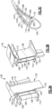
- Figure 3A shows a combination 126 with structure to "focus" cooling on localized areas that are most in need.
- the spar 132 has a front edge that varies in thickness from a relatively small portion 134 to a ramped portion 136 that leads to an enlarged area 138, and back to a ramped portion 140 that leads to the end 142 of the spar 132.
- the aft edge has a similar series of changes in its length.
- Figure 3B shows the combination 126, and the spar 132 also having similarly small outer portions 144 leading into a ramped portion 146, and enlarged portion 148, another ramped portion 150 and a smaller end portion 152. While this is shown on the suction side of the stator vane body 128 a similar shape would be found on the pressure side. As mentioned above, there is a cooling path defined between the outer surface of the spar 132 and an inner surface of the channel 112.
- Figure 3C shows the front edge 300 and the aft edge 303 of the spar 132 through a section taking at the point where the thinner portion 140 merges into the ramped portion 146.
- the cross-sectional area defined between the outer surface of the spar 132 and the inner surface 122 of the channel 112 will decrease as the cooling air moves toward a midspan region. This will increase the velocity of the air flow, and result in more concentrated cooling along this midspan portion.
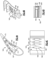
- Figure 4A shows another embodiment 160 where the spar 164 may have a relatively constant outer shape, but an inner surface 166 of the channel 167 has ridges or steps 170, 171, 172 and 173 formed along the suction side, leading edge, pressure side and trailing edge, respectively.
- the steps or ramps 172 will decrease the cross-sectional area of the flow adjacent a midspan area 168 by having a ramp portion 186 leading into thicker portions 182 and 184, and to another ramp 180.
- the ridges or steps 172 need not be spaced by a constant axial distance. Instead, there is a greater axial distance between adjacent ramps 172 as shown at 400 compared to a distance shown at 401 between the ridges or steps 172. This can allow further tailoring of the cooling air flow to specific areas.
- Figure 4D shows an alternative embodiment wherein the ridges or steps 190 are formed by a plurality of discrete incremental steps 192/194/196/198 away from the inner surface 200. This is in contrast to the ramped increases as shown in Figures 4A-4C . It may be easier to manufacture such a shape on the CMC stator body 162.
- Figure 5A shows an embodiment 210 having a stator vane body 212 where the spar 214 again has the surfaces 134/136/138/140/142 adjacent both the front edge and an aft edge.
- Figure 5B shows that the combination 210 includes surfaces on the spar 214 such as previously described in Figure 3B , and in particular surfaces 140/146/148/150 and 152.
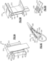
- the spar 214 has additional ridges or steps 220 similar to those found in the embodiment of Figures 4A-4C , but now on the spar 214.
- the steps 220 have a chevron shape with a ramped portion 226 leading into a thicker portion 222 and then into another ramp portion 228 such that the flow cross-section varies along a length of the spar 214.
- Figure 6A shows yet another embodiment 299 which essentially combines a spar 314 which may be similar to the Figure 3A-3C spar.
- a stator vane body 301 has ridges or steps 310 extending from an inner surface 311.
- Figure 6B shows the steps 310 on the body 301, and again show the ramps 305 leading into outwardly extending sections 318, inwardly extending sections 320 and another ramped portion 321.
- this embodiment combines the features of the Figures 3A-3C and Figures 4A-4C, or 4D .
- the several embodiments can be utilized to provided localized cooling to an area of the stator vane body which is most in need of cooling airflow.
Landscapes
- Engineering & Computer Science (AREA)
- Mechanical Engineering (AREA)
- General Engineering & Computer Science (AREA)
- Chemical & Material Sciences (AREA)
- Materials Engineering (AREA)
- Ceramic Engineering (AREA)
- Physics & Mathematics (AREA)
- Fluid Mechanics (AREA)
- Composite Materials (AREA)
- Turbine Rotor Nozzle Sealing (AREA)
- Structures Of Non-Positive Displacement Pumps (AREA)
Abstract
Description
- This application relates to a vane for use in a gas turbine engine which includes an internal spar, and defining a cooling air flow path with an inner surface of the vane.
- Gas turbine engines are known, and typically include a fan delivering air into a bypass duct as propulsion air. Air is also delivered into a compressor where it is compressed and delivered into a combustor. In the combustor the air is mixed with fuel and ignited. Products of this combustion pass downstream over turbine rotors, driving them to rotate. The turbine rotors drive the fan and compressor rotors.
- As is known, the turbine section of a gas turbine engine sees very high temperatures. As such, various steps are taken to ensure components in the turbine section can survive the high temperatures. One recent development is the use of ceramic matrix composites ("CMC") for components in the turbine section. One such component is a stator vane, which are mounted circumferentially spaced in rows that are axially intermediate rotating turbine blade rows.
- A CMC vane typically has an internal metal spar providing additional structural support. An outer surface of the spar defines a cooling air flow path in combination with an inner surface of a cooling channel in the CMC stator body.
- In an aspect of the present invention, a gas turbine engine stator vane combination includes a stator vane body having an airfoil with a leading edge, a trailing edge, a suction side and a pressure side, and having at least one internal cooling channel. The stator vane body is formed of ceramic matrix composite materials. A spar is received within the at least one cooling air channel and formed of a metal. The spar has an outer peripheral surface spaced from an inner peripheral surface of the cooling air channel to define a cooling air path, with the cooling air path having a varying cross-sectional area through the cooling air channel.
- In an embodiment, the stator vane body has platforms at each of two radial ends of the airfoil, and the spar extends through the cooling air channel and beyond each of the platforms.
- In another embodiment according to any of the previous embodiments, the spar has a leading (front) edge end, a trailing (aft) edge end, a suction wall face and a pressure wall face all associated with corresponding structure on the stator vane body. A first axial distance is defined between the front edge end and the aft edge end of the spar. A second axial distance is defined between the leading edge of the stator vane body and the trailing edge of the stator vane body and the first distance being between 10 and 90% of the second distance.
- In another embodiment according to any of the previous embodiments, the variable cross-sectional area is achieved by the spar having a variation in the outer peripheral surface, with a thinner portion leading into an outwardly first ramped portion at each of the leading edge, the trailing edge, the suction wall face and the pressure wall face of the spar to change the cross-sectional area.
- In another embodiment according to any of the previous embodiments, there is a second ramped portion beyond the enlarged portion that ramps back to a thinner portion such that the cross-sectional area of the cooling air path decreases at the first ramped portion and increases at the second ramped portion.
- In another embodiment according to any of the previous embodiments, there are enlarged surface portions formed in the cooling air path to further provide a reduction in cross-sectional area of the cooling air path at localized areas.
- In another embodiment according to any of the previous embodiments, the enlarged surface portions are formed on the inner peripheral surface of the stator vane body.
- In another embodiment according to any of the previous embodiments, the enlarged surface portions are formed on the outer peripheral surface of the spar.
- In another embodiment according to any of the previous embodiments, the enlarged surface portions have ramped portions leading from thinner portions into thicker portions to vary the cross-sectional area.
- In another embodiment according to any of the previous embodiments, the enlarged surface portions have discrete steps to change the cross-sectional area.
- In another embodiment according to any of the previous embodiments, the enlarged surface portions are formed on the inner surface of the stator vane body.
- In another embodiment according to any of the previous embodiments, there are enlarged surface portions formed in the cooling air path to provide a reduction in cross-sectional area of the cooling air path at localized areas.
- In another embodiment according to any of the previous embodiments, the enlarged portions have ramped portions leading from thinner portions into thicker portions to vary the cross-sectional area.
- In another embodiment according to any of the previous embodiments, the enlarged portions have discrete steps to change the cross-sectional area.
- In another embodiment according to any of the previous embodiments, the enlarged surface portions are formed on the outer peripheral surface of the spar.
- In another embodiment according to any of the previous embodiments, the enlarged surface portions are formed on the inner surface of the stator vane body.
- In another aspect of the present invention, a gas turbine engine includes a compressor section, a combustor section and a turbine section. The turbine section has alternating rows of rotating turbine blades, and rows of stator vanes, with at least one row of the stator vanes being formed of ceramic matrix composite materials. The stator vanes have a stator vane body having an airfoil with a leading edge, a trailing edge, a suction side and a pressure side, and having at least one internal cooling channel. The stator vane body is formed of ceramic matrix composite materials. A spar is received within the at least one cooling air channel and formed of a metal. The spar has an outer peripheral surface spaced from an inner peripheral surface of the cooling air channel to define a cooling air path, with the cooling air path having a varying cross-sectional area through the cooling air channel.
- In an embodiment, the spar has a leading edge end, a trailing edge end, a suction wall face and a pressure wall face all associated with corresponding structure on the stator vane body. A first axial distance is defined between the front edge and the aft edge end of the spar. A second axial distance is defined between the leading edge of the stator vane body and the trailing edge of the stator vane body and the first distance being between 10 and 90% of the second distance.
- In another embodiment according to any of the previous embodiments, the variable cross-sectional area is achieved by the spar having a variation in the outer surface with there being a thinner portion leading into an outwardly ramped portion at each of the front edge, the aft edge, the suction wall face and the pressure wall face of the spar to change the cross-sectional area.
- In another embodiment according to any of the previous embodiments, there are enlarged surface portions formed in the cooling air path to provide a reduction in cross-sectional area of the cooling air path at localized areas.
- The present disclosure may include any one or more of the individual features disclosed above and/or below alone or in any combination thereof.
- These and other features of the present invention can be best understood from the following specification and drawings, the following of which is a brief description.
-
-
Figure 1 schematically shows a gas turbine engine. -
Figure 2A shows a stator vane. -
Figure 2B shows a stator vane body. -
Figure 2C is a cross-sectional view through theFigure 2A stator vane and spar combination. -
Figure 3A shows a first embodiment stator vane and spar combination. -
Figure 3B shows an additional view of theFigure 3A combination. -
Figure 3C is a top view looking into the embodiment ofFigures 3A and 3B . -
Figure 4A shows another embodiment stator vane and spar combination. -
Figure 4B shows a detail of theFigure 4A embodiment. -
Figure 4C shows a further detail of an inner wall of this embodiment. -
Figure 4D shows an alternative embodiment of theFigure 4A combination. -
Figure 5A shows yet another embodiment stator vane and spar combination. -
Figure 5B shows another view of theFigure 5A combination. -
Figure 5C is a view looking downward into a cooling channel of theFigure 5A and 5B embodiment. -
Figure 5D shows yet another feature of theFigure 5A-5C embodiment. -
Figure 6A shows another embodiment stator vane and spare combination. -
Figure 6B shows a detail of theFigure 6A embodiment. -
Figure 1 schematically illustrates agas turbine engine 20. Thegas turbine engine 20 is disclosed herein as a two-spool turbofan that generally incorporates afan section 22, acompressor section 24, a combustor section 26 and aturbine section 28. Thefan section 22 may include a single-stage fan 42 having a plurality offan blades 43. Thefan blades 43 may have a fixed stagger angle or may have a variable pitch to direct incoming airflow from an engine inlet. Thefan 42 drives air along a bypass flow path B in abypass duct 13 defined within ahousing 15 such as a fan case or nacelle, and also drives air along a core flow path C for compression and communication into the combustor section 26 then expansion through theturbine section 28. Asplitter 29 aft of thefan 42 divides the air between the bypass flow path B and the core flow path C. Thehousing 15 may surround thefan 42 to establish an outer diameter of thebypass duct 13. Thesplitter 29 may establish an inner diameter of thebypass duct 13. Although depicted as a two-spool turbofan gas turbine engine in the disclosed non-limiting embodiment, it should be understood that the concepts described herein are not limited to use with two-spool turbofans as the teachings may be applied to other types of turbine engines including three-spool architectures. Theengine 20 may incorporate a variable area nozzle for varying an exit area of the bypass flow path B and/or a thrust reverser for generating reverse thrust. - The
exemplary engine 20 generally includes alow speed spool 30 and ahigh speed spool 32 mounted for rotation about an engine central longitudinal axis A relative to an enginestatic structure 36 viaseveral bearing systems 38. It should be understood that various bearingsystems 38 at various locations may alternatively or additionally be provided, and the location of bearingsystems 38 may be varied as appropriate to the application. - The
low speed spool 30 generally includes aninner shaft 40 that interconnects, a first (or low) pressure compressor 44 and a first (or low)pressure turbine 46. Theinner shaft 40 is connected to thefan 42 through a speed change mechanism, which in the exemplarygas turbine engine 20 is illustrated as a gearedarchitecture 48 to drive thefan 42 at a lower speed than thelow speed spool 30. Theinner shaft 40 may interconnect the low pressure compressor 44 andlow pressure turbine 46 such that the low pressure compressor 44 andlow pressure turbine 46 are rotatable at a common speed and in a common direction. In other embodiments, thelow pressure turbine 46 drives both thefan 42 and low pressure compressor 44 through the gearedarchitecture 48 such that thefan 42 and low pressure compressor 44 are rotatable at a common speed. Although this application discloses gearedarchitecture 48, its teaching may benefit direct drive engines having no geared architecture. Thehigh speed spool 32 includes an outer shaft 50 that interconnects a second (or high)pressure compressor 52 and a second (or high)pressure turbine 54. Acombustor 56 is arranged in theexemplary gas turbine 20 between thehigh pressure compressor 52 and thehigh pressure turbine 54. Amid-turbine frame 57 of the enginestatic structure 36 may be arranged generally between thehigh pressure turbine 54 and thelow pressure turbine 46. Themid-turbine frame 57 furthersupports bearing systems 38 in theturbine section 28. Theinner shaft 40 and the outer shaft 50 are concentric and rotate via bearingsystems 38 about the engine central longitudinal axis A which is collinear with their longitudinal axes. - Airflow in the core flow path C is compressed by the low pressure compressor 44 then the
high pressure compressor 52, mixed and burned with fuel in thecombustor 56, then expanded through thehigh pressure turbine 54 andlow pressure turbine 46. Themid-turbine frame 57 includesairfoils 59 which are in the core flow path C. Theturbines low speed spool 30 andhigh speed spool 32 in response to the expansion. It will be appreciated that each of the positions of thefan section 22,compressor section 24, combustor section 26,turbine section 28, and fandrive gear system 48 may be varied. For example,gear system 48 may be located aft of the low pressure compressor, or aft of the combustor section 26 or even aft ofturbine section 28, andfan 42 may be positioned forward or aft of the location ofgear system 48. - The low pressure compressor 44,
high pressure compressor 52,high pressure turbine 54 andlow pressure turbine 46 each include one or more stages having a row of rotatable airfoils. Each stage may include a row of vanes adjacent the rotatable airfoils. The rotatable airfoils are schematically indicated at 47, and the vanes are schematically indicated at 49. - The
engine 20 may be a high-bypass geared aircraft engine. The bypass ratio can be greater than or equal to 10.0 and less than or equal to about 18.0, or more narrowly can be less than or equal to 16.0. The gearedarchitecture 48 may be an epicyclic gear train, such as a planetary gear system or a star gear system. The epicyclic gear train may include a sun gear, a ring gear, a plurality of intermediate gears meshing with the sun gear and ring gear, and a carrier that supports the intermediate gears. The sun gear may provide an input to the gear train. The ring gear (e.g., star gear system) or carrier (e.g., planetary gear system) may provide an output of the gear train to drive thefan 42. A gear reduction ratio may be greater than or equal to 2.3, or more narrowly greater than or equal to 3.0, and in some embodiments the gear reduction ratio is greater than or equal to 3.4. The gear reduction ratio may be less than or equal to 4.0. The fan diameter is significantly larger than that of the low pressure compressor 44. Thelow pressure turbine 46 can have a pressure ratio that is greater than or equal to 8.0 and in some embodiments is greater than or equal to 10.0. The low pressure turbine pressure ratio can be less than or equal to 13.0, or more narrowly less than or equal to 12.0.Low pressure turbine 46 pressure ratio is pressure measured prior to an inlet oflow pressure turbine 46 as related to the pressure at the outlet of thelow pressure turbine 46 prior to an exhaust nozzle. It should be understood, however, that the above parameters are only exemplary of one embodiment of a geared architecture engine and that the present invention is applicable to other gas turbine engines including direct drive turbofans. All of these parameters are measured at the cruise condition described below. - A significant amount of thrust is provided by the bypass flow B due to the high bypass ratio. The
fan section 22 of theengine 20 is designed for a particular flight condition -- typically cruise at about 0.8 Mach and about 35,000 feet (10,668 meters). The flight condition of 0.8 Mach and 35,000 ft (10,668 meters), with the engine at its best fuel consumption - also known as "bucket cruise Thrust Specific Fuel Consumption ('TSFC')" - is the industry standard parameter of Ibm of fuel being burned divided by Ibf of thrust the engine produces at that minimum point. The engine parameters described above, and those in the next paragraph are measured at this condition unless otherwise specified. - "Fan pressure ratio" is the pressure ratio across the
fan blade 43 alone, without a Fan Exit Guide Vane ("FEGV") system. A distance is established in a radial direction between the inner and outer diameters of thebypass duct 13 at an axial position corresponding to a leading edge of thesplitter 29 relative to the engine central longitudinal axis A. The fan pressure ratio is a spanwise average of the pressure ratios measured across thefan blade 43 alone over radial positions corresponding to the distance. The fan pressure ratio can be less than or equal to 1.45, or more narrowly greater than or equal to 1.25, such as between 1.30 and 1.40. "Corrected fan tip speed" is the actual fan tip speed in ft/sec divided by an industry standard temperature correction of [(Tram °R) / (518.7 °R)]0.5. The corrected fan tip speed can be less than or equal to 1150.0 ft / second (350.5 meters/second), and can be greater than or equal to 1000.0 ft / second (304.8 meters/second). -
Figure 2A shows astator vane body 102 and aninternal spar 104 as a combinedelement 100. Stator vanes typically includeplatforms airfoil 99. Applicant has discovered that the heating load on theairfoil 99 is not uniform, and may be highest adjacent amidspan 102M. - The
stator vane body 102 may be formed of ceramic matrix composites ("CMCs"). - In embodiments, the ceramic matrix components could be formed of CMC material or a monolithic ceramic. A CMC material is comprised of one or more ceramic fiber plies in a ceramic matrix. Example ceramic matrices are silicon-containing ceramic, such as but not limited to, a silicon carbide (SiC) matrix or a silicon nitride (Si3N4) matrix. Example ceramic reinforcement of the CMC are silicon-containing ceramic fibers, such as but not limited to, silicon carbide (SiC) fiber or silicon nitride (Si3N4) fibers. The CMC may be, but is not limited to, a SiC/SiC ceramic matrix composite in which SiC fiber plies are disposed within a SiC matrix. A fiber ply has a fiber architecture, which refers to an ordered arrangement of the fiber tows relative to one another, such as a 2D woven ply or a 3D structure. A monolithic ceramic does not contain fibers or reinforcement and is formed of a single material. Example monolithic ceramics include silicon-containing ceramics, such as silicon carbide (SiC) or silicon nitride (Si3N4).
- As mentioned above, there is a
cooling channel 112 that receives cooling air from asource 101 such as a compressor section in theFigure 1 engine. The air is delivered throughconduits 103 into acooling channel 112 and, optionally, into asecond cooling channel 114. Of course, additional cooling channels may be used. Theinternal spar 104 may be formed of an appropriate metal, and provides additional structural ability to thecombination 100. As shown, thespar 104 has aremote end 111 which extends beyond theplatform 110. Anouter surface 106 of thespar 104 is generally shaped as an airfoil. -
Spar 104 is illustrated in a schematic manner to show the cooling features. The actual spar may itself have internal cooling passages. Further, its outer shape may differ. Also, some attachment structure will typically be included. -
Figure 2B shows the coolingchannels stator vane body 102. -
Figure 2C shows a cross-section through thecombination 100. In particular, thespar 104 has itsouter surface 106 spaced away from aninner surface 107 of thestator vane body 102. Between thesurfaces 107 and 106 a cooling air path is defined. - The
stator vane body 102 has aleading edge 116 and a trailingedge 118.Spar 104 has afront edge 117 and anaft edge 119. In an embodiment, a length measured between thefront edge 117 andaft edge 119 is greater than or equal to 10% and less than or equal to 90% of a distance measured between leadingedge 116 and trailingedge 118. In other embodiments it may be greater than or equal to 20% and less than or equal to 80% of the distance. In further embodiments, it may be greater than or equal to 40% and less than or equal to 90% of the distance. - As mentioned above, Applicant has recognized that the cooling load is not constant along the
surfaces midspan location 102M. -
Figure 3A shows acombination 126 with structure to "focus" cooling on localized areas that are most in need. As shown, thespar 132 has a front edge that varies in thickness from a relativelysmall portion 134 to a rampedportion 136 that leads to anenlarged area 138, and back to a rampedportion 140 that leads to theend 142 of thespar 132. The aft edge has a similar series of changes in its length. -
Figure 3B shows thecombination 126, and thespar 132 also having similarly smallouter portions 144 leading into a rampedportion 146, andenlarged portion 148, another rampedportion 150 and asmaller end portion 152. While this is shown on the suction side of the stator vane body 128 a similar shape would be found on the pressure side. As mentioned above, there is a cooling path defined between the outer surface of thespar 132 and an inner surface of thechannel 112. -
Figure 3C shows thefront edge 300 and theaft edge 303 of thespar 132 through a section taking at the point where thethinner portion 140 merges into the rampedportion 146. As can be appreciated, due to the ramped portions found along each of the pressure and suction sides, and adjacent the front and aft edges, the cross-sectional area defined between the outer surface of thespar 132 and theinner surface 122 of thechannel 112 will decrease as the cooling air moves toward a midspan region. This will increase the velocity of the air flow, and result in more concentrated cooling along this midspan portion. -
Figure 4A shows anotherembodiment 160 where thespar 164 may have a relatively constant outer shape, but aninner surface 166 of thechannel 167 has ridges orsteps - As can be seen in
Figure 4B , the steps orramps 172 will decrease the cross-sectional area of the flow adjacent amidspan area 168 by having aramp portion 186 leading intothicker portions ramp 180. - As shown in
Figure 4C , the ridges orsteps 172 need not be spaced by a constant axial distance. Instead, there is a greater axial distance betweenadjacent ramps 172 as shown at 400 compared to a distance shown at 401 between the ridges or steps 172. This can allow further tailoring of the cooling air flow to specific areas. -
Figure 4D shows an alternative embodiment wherein the ridges orsteps 190 are formed by a plurality of discreteincremental steps 192/194/196/198 away from theinner surface 200. This is in contrast to the ramped increases as shown inFigures 4A-4C . It may be easier to manufacture such a shape on theCMC stator body 162. -
Figure 5A shows anembodiment 210 having astator vane body 212 where thespar 214 again has thesurfaces 134/136/138/140/142 adjacent both the front edge and an aft edge. -
Figure 5B shows that thecombination 210 includes surfaces on thespar 214 such as previously described inFigure 3B , and inparticular surfaces 140/146/148/150 and 152. - However, as shown in
Figure 5C , thespar 214 has additional ridges orsteps 220 similar to those found in the embodiment ofFigures 4A-4C , but now on thespar 214. As can be seen inFigure 5D , thesteps 220 have a chevron shape with a rampedportion 226 leading into athicker portion 222 and then into anotherramp portion 228 such that the flow cross-section varies along a length of thespar 214. -
Figure 6A shows yet anotherembodiment 299 which essentially combines aspar 314 which may be similar to theFigure 3A-3C spar. In addition, astator vane body 301 has ridges orsteps 310 extending from aninner surface 311. -
Figure 6B shows thesteps 310 on thebody 301, and again show theramps 305 leading into outwardly extendingsections 318, inwardly extendingsections 320 and another rampedportion 321. Essentially, this embodiment combines the features of theFigures 3A-3C andFigures 4A-4C, or 4D . - Now, the several embodiments can be utilized to provided localized cooling to an area of the stator vane body which is most in need of cooling airflow.
- While embodiments have been disclosed, a worker of skill in this art would recognize that modifications within the scope of this disclosure. For that reason, the following claims should be studied to determine the true scope and content of this disclosure.
Claims (11)
- A gas turbine engine stator vane combination (100; 126; 160; 210; 299) comprising:a stator vane body (102; 128; 162; 212; 301) having an airfoil (99) with a leading edge (116), a trailing edge (118), a suction side and a pressure side, and having at least one internal cooling air channel (112), said stator vane body (102...301) being formed of ceramic matrix composite materials;a spar (104; 132; 164; 214; 314) received within said at least one cooling air channel (112) and formed of a metal, and said spar (104...314) having an outer peripheral surface (106) spaced from an inner peripheral surface (107; 122; 166; 200; 311) of the cooling air channel (112) to define a cooling air path, with said cooling air path having a varying cross-sectional area through the cooling air channel (112).
- The stator vane combination as set forth in claim 1, wherein said stator vane body (102... 301) has platforms (108, 110) at each of two radial ends of said airfoil (99), and said spar (104...314) extends through said cooling air channel (112) and beyond each of said platforms (108, 110).
- The stator vane combination as set forth in claim 1 or 2, wherein said spar (104...314) has a leading edge end (117; 300), a trailing edge end (119; 303), a suction wall face and a pressure wall face all associated with corresponding structure on said stator vane body (102...301), and a first axial distance defined between said leading edge end (117; 300) and said trailing edge end (119; 303) of said spar (104...314), and a second axial distance defined between said leading edge (116) of said stator vane body (102... 301) and said trailing edge (118) of said stator vane body (102...301) and said first axial distance being between 10% and 90% of said second axial distance.
- The stator vane combination as set forth in claim 1, 2 or 3, wherein said variable cross-sectional area is achieved by said spar (104...314) having a variation in said outer peripheral surface (106), with a first thinner portion (134; 144) leading into an outwardly first ramped portion (136, 146) at each of a or said leading edge end (117; 300), trailing edge end (119; 300), suction wall face and pressure wall face of said spar (104...314) to change the cross-sectional area.
- The stator vane combination as set forth in claim 4, wherein there is a second ramped portion (140, 150) beyond said first ramped portion (136, 146), and said second ramped portion (140, 150) ramps back to a second thinner portion (142, 152) such that the cross-sectional area of the cooling air path decreases at the first ramped portion (136, 146) and increases at the second ramped portion (140,; 150).
- The stator vane combination as set forth in any preceding claim, wherein there are enlarged surface portions (138, 148; 170-173; 190; 220; 310) formed in said cooling air path to further provide a reduction in cross-sectional area of the cooling air path at localized areas.
- The stator vane combination as set forth in claim 6, wherein said enlarged surface portions (170-173; 190; 310) are formed on the inner peripheral surface (166...311) of said stator vane body (162...301).
- The stator vane combination as set forth in claim 6, wherein said enlarged surface portions (138; 148; 220) are formed on the outer peripheral surface (106) of said spar (104...314).
- The stator vane combination as set forth in claim 6, 7 or 8, wherein said enlarged surface portions (138, 148; 172) have ramped portions (136, 140, 146, 150; 180, 186) leading from thinner portions (134, 142, 146, 152) into thicker portions (182, 184) to vary the cross-sectional area.
- The stator vane combination as set forth in any of claims 6 to 9, wherein said enlarged surface portions (170...310) have discrete steps (192-198) to change the cross-sectional area.
- A gas turbine engine (20) comprising:
a compressor section (24), a combustor section (26) and a turbine section (28), said turbine section (28) having alternating rows of rotating turbine blades (47), and rows of stator vanes (49), with at least one row of said stator vanes (49) being formed of ceramic matrix composite materials, said stator vanes (49) comprising the stator vane combination (100...299) of any preceding claim.
Applications Claiming Priority (1)
| Application Number | Priority Date | Filing Date | Title |
|---|---|---|---|
| US17/964,355 US11913348B1 (en) | 2022-10-12 | 2022-10-12 | Gas turbine engine vane and spar combination with variable air flow path |
Publications (2)
| Publication Number | Publication Date |
|---|---|
| EP4353949A1 true EP4353949A1 (en) | 2024-04-17 |
| EP4353949B1 EP4353949B1 (en) | 2025-07-16 |
Family
ID=88315338
Family Applications (1)
| Application Number | Title | Priority Date | Filing Date |
|---|---|---|---|
| EP23202830.8A Active EP4353949B1 (en) | 2022-10-12 | 2023-10-10 | Gas turbine engine vane and spar combination with variable air flow path |
Country Status (2)
| Country | Link |
|---|---|
| US (2) | US11913348B1 (en) |
| EP (1) | EP4353949B1 (en) |
Cited By (1)
| Publication number | Priority date | Publication date | Assignee | Title |
|---|---|---|---|---|
| US20250283419A1 (en) * | 2022-07-20 | 2025-09-11 | Ge Vernova Infrastructure Technology Llc | Cooling circuit for a stator vane braze joint |
Citations (5)
| Publication number | Priority date | Publication date | Assignee | Title |
|---|---|---|---|---|
| US20160208621A1 (en) * | 2013-09-06 | 2016-07-21 | United Technologies Corporation | Gas turbine engine airfoil with wishbone baffle cooling scheme |
| US20210140326A1 (en) * | 2019-11-08 | 2021-05-13 | United Technologies Corporation | Vane with seal |
| US11346228B1 (en) * | 2021-02-23 | 2022-05-31 | Raytheon Technologies Corporation | Airfoil with flange formed of wishbone-shaped fiber layer structure |
| US11359497B1 (en) * | 2020-12-21 | 2022-06-14 | Raytheon Technologies Corporation | Vane with baffle and recessed spar |
| US11391162B2 (en) * | 2020-12-15 | 2022-07-19 | Raytheon Technologies Corporation | Spar with embedded plenum passage |
Family Cites Families (27)
| Publication number | Priority date | Publication date | Assignee | Title |
|---|---|---|---|---|
| GB0222352D0 (en) * | 2002-09-26 | 2002-11-06 | Dorling Kevin | Turbine blade turbulator cooling design |
| US6929445B2 (en) * | 2003-10-22 | 2005-08-16 | General Electric Company | Split flow turbine nozzle |
| US7452182B2 (en) * | 2005-04-07 | 2008-11-18 | Siemens Energy, Inc. | Multi-piece turbine vane assembly |
| US7862291B2 (en) * | 2007-02-08 | 2011-01-04 | United Technologies Corporation | Gas turbine engine component cooling scheme |
| JP5931351B2 (en) * | 2011-05-13 | 2016-06-08 | 三菱重工業株式会社 | Turbine vane |
| US8807945B2 (en) * | 2011-06-22 | 2014-08-19 | United Technologies Corporation | Cooling system for turbine airfoil including ice-cream-cone-shaped pedestals |
| US9200536B2 (en) * | 2011-10-17 | 2015-12-01 | United Technologies Corporation | Mid turbine frame (MTF) for a gas turbine engine |
| US9759072B2 (en) * | 2012-08-30 | 2017-09-12 | United Technologies Corporation | Gas turbine engine airfoil cooling circuit arrangement |
| US9334755B2 (en) * | 2012-09-28 | 2016-05-10 | United Technologies Corporation | Airfoil with variable trip strip height |
| WO2014159800A1 (en) * | 2013-03-14 | 2014-10-02 | United Technologies Corporation | Obtuse angle chevron trip strip |
| US9982567B2 (en) * | 2014-12-16 | 2018-05-29 | United Technologies Corporation | Gas turbine engine mid-turbine frame tie rod arrangement |
| US9915159B2 (en) * | 2014-12-18 | 2018-03-13 | General Electric Company | Ceramic matrix composite nozzle mounted with a strut and concepts thereof |
| US9777635B2 (en) * | 2014-12-31 | 2017-10-03 | General Electric Company | Engine component |
| US9982543B2 (en) * | 2015-08-05 | 2018-05-29 | United Technologies Corporation | Partial cavity baffles for airfoils in gas turbine engines |
| US11230935B2 (en) * | 2015-09-18 | 2022-01-25 | General Electric Company | Stator component cooling |
| US10612399B2 (en) * | 2018-06-01 | 2020-04-07 | Rolls-Royce North American Technologies Inc. | Turbine vane assembly with ceramic matrix composite components |
| US10830063B2 (en) * | 2018-07-20 | 2020-11-10 | Rolls-Royce North American Technologies Inc. | Turbine vane assembly with ceramic matrix composite components |
| US10934868B2 (en) * | 2018-09-12 | 2021-03-02 | Rolls-Royce North American Technologies Inc. | Turbine vane assembly with variable position support |
| US11149568B2 (en) | 2018-12-20 | 2021-10-19 | Rolls-Royce Plc | Sliding ceramic matrix composite vane assembly for gas turbine engines |
| US10711621B1 (en) * | 2019-02-01 | 2020-07-14 | Rolls-Royce Plc | Turbine vane assembly with ceramic matrix composite components and temperature management features |
| US10975708B2 (en) * | 2019-04-23 | 2021-04-13 | Rolls-Royce Plc | Turbine section assembly with ceramic matrix composite vane |
| US10954802B2 (en) * | 2019-04-23 | 2021-03-23 | Rolls-Royce Plc | Turbine section assembly with ceramic matrix composite vane |
| US11365635B2 (en) | 2019-05-17 | 2022-06-21 | Raytheon Technologies Corporation | CMC component with integral cooling channels and method of manufacture |
| US11371360B2 (en) * | 2019-06-05 | 2022-06-28 | Raytheon Technologies Corporation | Components for gas turbine engines |
| EP3805525A1 (en) * | 2019-10-09 | 2021-04-14 | Rolls-Royce plc | Turbine vane assembly incorporating ceramic matric composite materials |
| US11268392B2 (en) * | 2019-10-28 | 2022-03-08 | Rolls-Royce Plc | Turbine vane assembly incorporating ceramic matrix composite materials and cooling |
| US11591921B1 (en) * | 2021-11-05 | 2023-02-28 | Rolls-Royce Plc | Ceramic matrix composite vane assembly |
-
2022
- 2022-10-12 US US17/964,355 patent/US11913348B1/en active Active
-
2023
- 2023-10-10 EP EP23202830.8A patent/EP4353949B1/en active Active
- 2023-12-19 US US18/545,092 patent/US12326093B2/en active Active
Patent Citations (5)
| Publication number | Priority date | Publication date | Assignee | Title |
|---|---|---|---|---|
| US20160208621A1 (en) * | 2013-09-06 | 2016-07-21 | United Technologies Corporation | Gas turbine engine airfoil with wishbone baffle cooling scheme |
| US20210140326A1 (en) * | 2019-11-08 | 2021-05-13 | United Technologies Corporation | Vane with seal |
| US11391162B2 (en) * | 2020-12-15 | 2022-07-19 | Raytheon Technologies Corporation | Spar with embedded plenum passage |
| US11359497B1 (en) * | 2020-12-21 | 2022-06-14 | Raytheon Technologies Corporation | Vane with baffle and recessed spar |
| US11346228B1 (en) * | 2021-02-23 | 2022-05-31 | Raytheon Technologies Corporation | Airfoil with flange formed of wishbone-shaped fiber layer structure |
Cited By (1)
| Publication number | Priority date | Publication date | Assignee | Title |
|---|---|---|---|---|
| US20250283419A1 (en) * | 2022-07-20 | 2025-09-11 | Ge Vernova Infrastructure Technology Llc | Cooling circuit for a stator vane braze joint |
Also Published As
| Publication number | Publication date |
|---|---|
| EP4353949B1 (en) | 2025-07-16 |
| US11913348B1 (en) | 2024-02-27 |
| US20240125248A1 (en) | 2024-04-18 |
| US12326093B2 (en) | 2025-06-10 |
Similar Documents
| Publication | Publication Date | Title |
|---|---|---|
| EP4353949B1 (en) | Gas turbine engine vane and spar combination with variable air flow path | |
| US20250230751A1 (en) | Turbine blade with boomerang shaped wall cooling passages | |
| EP4513000A1 (en) | Bathtub seal for damping cmc vane platform | |
| EP4379187A1 (en) | Gas turbine engine component having an airfoil with internal cross-ribs | |
| EP4379190B1 (en) | Removable layer to adjust mount structure of a turbine vane for re-stagger | |
| EP4345256B1 (en) | Gas turbine engine and gas turbine engine component | |
| EP4372207B1 (en) | Blade outer air seal with large radius of curvature mount hooks | |
| EP4549701B1 (en) | Combined gas turbine engine vane and blade outer air seal assembly and gas turbine engine | |
| EP4603246A1 (en) | Multi-piece mandrel for building up airfoil structure | |
| US12601267B2 (en) | Forming gas turbine engine airfoils from CMCs with a kickback to facilitate mandrel removal | |
| EP4361405A1 (en) | Gas turbine engine turbine section with axial seal | |
| EP4325029B1 (en) | Gas turbine engine stator vanes formed of ceramic matrix composites and having attachment flanges | |
| US12448708B2 (en) | Extended inner profile for mandrel for use in forming braided CMC structures | |
| EP4293197A1 (en) | Component for a gas turbine engine and gas turbine engine | |
| US12428965B2 (en) | Load bearing feature for ceramic matrix composite turbine components | |
| US12326100B1 (en) | Gas turbine engine component fillets formed of CMC plies | |
| EP4517049A1 (en) | Bathtub seal integrated into cmc vane load path |
Legal Events
| Date | Code | Title | Description |
|---|---|---|---|
| PUAI | Public reference made under article 153(3) epc to a published international application that has entered the european phase |
Free format text: ORIGINAL CODE: 0009012 |
|
| STAA | Information on the status of an ep patent application or granted ep patent |
Free format text: STATUS: THE APPLICATION HAS BEEN PUBLISHED |
|
| AK | Designated contracting states |
Kind code of ref document: A1 Designated state(s): AL AT BE BG CH CY CZ DE DK EE ES FI FR GB GR HR HU IE IS IT LI LT LU LV MC ME MK MT NL NO PL PT RO RS SE SI SK SM TR |
|
| STAA | Information on the status of an ep patent application or granted ep patent |
Free format text: STATUS: REQUEST FOR EXAMINATION WAS MADE |
|
| 17P | Request for examination filed |
Effective date: 20241017 |
|
| RBV | Designated contracting states (corrected) |
Designated state(s): AL AT BE BG CH CY CZ DE DK EE ES FI FR GB GR HR HU IE IS IT LI LT LU LV MC ME MK MT NL NO PL PT RO RS SE SI SK SM TR |
|
| GRAP | Despatch of communication of intention to grant a patent |
Free format text: ORIGINAL CODE: EPIDOSNIGR1 |
|
| STAA | Information on the status of an ep patent application or granted ep patent |
Free format text: STATUS: GRANT OF PATENT IS INTENDED |
|
| RIC1 | Information provided on ipc code assigned before grant |
Ipc: F01D 9/06 20060101ALI20250129BHEP Ipc: F01D 5/28 20060101ALI20250129BHEP Ipc: F01D 5/18 20060101AFI20250129BHEP |
|
| INTG | Intention to grant announced |
Effective date: 20250211 |
|
| GRAS | Grant fee paid |
Free format text: ORIGINAL CODE: EPIDOSNIGR3 |
|
| GRAA | (expected) grant |
Free format text: ORIGINAL CODE: 0009210 |
|
| STAA | Information on the status of an ep patent application or granted ep patent |
Free format text: STATUS: THE PATENT HAS BEEN GRANTED |
|
| AK | Designated contracting states |
Kind code of ref document: B1 Designated state(s): AL AT BE BG CH CY CZ DE DK EE ES FI FR GB GR HR HU IE IS IT LI LT LU LV MC ME MK MT NL NO PL PT RO RS SE SI SK SM TR |
|
| REG | Reference to a national code |
Ref country code: GB Ref legal event code: FG4D |
|
| REG | Reference to a national code |
Ref country code: CH Ref legal event code: EP |
|
| REG | Reference to a national code |
Ref country code: DE Ref legal event code: R096 Ref document number: 602023004851 Country of ref document: DE |
|
| REG | Reference to a national code |
Ref country code: IE Ref legal event code: FG4D |
|
| PGFP | Annual fee paid to national office [announced via postgrant information from national office to epo] |
Ref country code: FR Payment date: 20250924 Year of fee payment: 3 |
|
| REG | Reference to a national code |
Ref country code: NL Ref legal event code: MP Effective date: 20250716 |
|
| PG25 | Lapsed in a contracting state [announced via postgrant information from national office to epo] |
Ref country code: PT Free format text: LAPSE BECAUSE OF FAILURE TO SUBMIT A TRANSLATION OF THE DESCRIPTION OR TO PAY THE FEE WITHIN THE PRESCRIBED TIME-LIMIT Effective date: 20251117 |
|
| PG25 | Lapsed in a contracting state [announced via postgrant information from national office to epo] |
Ref country code: NL Free format text: LAPSE BECAUSE OF FAILURE TO SUBMIT A TRANSLATION OF THE DESCRIPTION OR TO PAY THE FEE WITHIN THE PRESCRIBED TIME-LIMIT Effective date: 20250716 |
|
| REG | Reference to a national code |
Ref country code: AT Ref legal event code: MK05 Ref document number: 1814217 Country of ref document: AT Kind code of ref document: T Effective date: 20250716 |
|
| PG25 | Lapsed in a contracting state [announced via postgrant information from national office to epo] |
Ref country code: IS Free format text: LAPSE BECAUSE OF FAILURE TO SUBMIT A TRANSLATION OF THE DESCRIPTION OR TO PAY THE FEE WITHIN THE PRESCRIBED TIME-LIMIT Effective date: 20251116 |
|
| PGFP | Annual fee paid to national office [announced via postgrant information from national office to epo] |
Ref country code: DE Payment date: 20250923 Year of fee payment: 3 |
|
| PG25 | Lapsed in a contracting state [announced via postgrant information from national office to epo] |
Ref country code: NO Free format text: LAPSE BECAUSE OF FAILURE TO SUBMIT A TRANSLATION OF THE DESCRIPTION OR TO PAY THE FEE WITHIN THE PRESCRIBED TIME-LIMIT Effective date: 20251016 |
|
| REG | Reference to a national code |
Ref country code: LT Ref legal event code: MG9D |
|
| PG25 | Lapsed in a contracting state [announced via postgrant information from national office to epo] |
Ref country code: AT Free format text: LAPSE BECAUSE OF FAILURE TO SUBMIT A TRANSLATION OF THE DESCRIPTION OR TO PAY THE FEE WITHIN THE PRESCRIBED TIME-LIMIT Effective date: 20250716 |
|
| PG25 | Lapsed in a contracting state [announced via postgrant information from national office to epo] |
Ref country code: FI Free format text: LAPSE BECAUSE OF FAILURE TO SUBMIT A TRANSLATION OF THE DESCRIPTION OR TO PAY THE FEE WITHIN THE PRESCRIBED TIME-LIMIT Effective date: 20250716 |
|
| PG25 | Lapsed in a contracting state [announced via postgrant information from national office to epo] |
Ref country code: HR Free format text: LAPSE BECAUSE OF FAILURE TO SUBMIT A TRANSLATION OF THE DESCRIPTION OR TO PAY THE FEE WITHIN THE PRESCRIBED TIME-LIMIT Effective date: 20250716 |
|
| PG25 | Lapsed in a contracting state [announced via postgrant information from national office to epo] |
Ref country code: GR Free format text: LAPSE BECAUSE OF FAILURE TO SUBMIT A TRANSLATION OF THE DESCRIPTION OR TO PAY THE FEE WITHIN THE PRESCRIBED TIME-LIMIT Effective date: 20251017 |
|
| PG25 | Lapsed in a contracting state [announced via postgrant information from national office to epo] |
Ref country code: SE Free format text: LAPSE BECAUSE OF FAILURE TO SUBMIT A TRANSLATION OF THE DESCRIPTION OR TO PAY THE FEE WITHIN THE PRESCRIBED TIME-LIMIT Effective date: 20250716 |
|
| PG25 | Lapsed in a contracting state [announced via postgrant information from national office to epo] |
Ref country code: LV Free format text: LAPSE BECAUSE OF FAILURE TO SUBMIT A TRANSLATION OF THE DESCRIPTION OR TO PAY THE FEE WITHIN THE PRESCRIBED TIME-LIMIT Effective date: 20250716 |
|
| PG25 | Lapsed in a contracting state [announced via postgrant information from national office to epo] |
Ref country code: PL Free format text: LAPSE BECAUSE OF FAILURE TO SUBMIT A TRANSLATION OF THE DESCRIPTION OR TO PAY THE FEE WITHIN THE PRESCRIBED TIME-LIMIT Effective date: 20250716 Ref country code: BG Free format text: LAPSE BECAUSE OF FAILURE TO SUBMIT A TRANSLATION OF THE DESCRIPTION OR TO PAY THE FEE WITHIN THE PRESCRIBED TIME-LIMIT Effective date: 20250716 |
|
| PG25 | Lapsed in a contracting state [announced via postgrant information from national office to epo] |
Ref country code: RS Free format text: LAPSE BECAUSE OF FAILURE TO SUBMIT A TRANSLATION OF THE DESCRIPTION OR TO PAY THE FEE WITHIN THE PRESCRIBED TIME-LIMIT Effective date: 20251016 |
|
| PG25 | Lapsed in a contracting state [announced via postgrant information from national office to epo] |
Ref country code: ES Free format text: LAPSE BECAUSE OF FAILURE TO SUBMIT A TRANSLATION OF THE DESCRIPTION OR TO PAY THE FEE WITHIN THE PRESCRIBED TIME-LIMIT Effective date: 20250716 |
|
| PG25 | Lapsed in a contracting state [announced via postgrant information from national office to epo] |
Ref country code: RO Free format text: LAPSE BECAUSE OF FAILURE TO SUBMIT A TRANSLATION OF THE DESCRIPTION OR TO PAY THE FEE WITHIN THE PRESCRIBED TIME-LIMIT Effective date: 20250716 |
|
| PG25 | Lapsed in a contracting state [announced via postgrant information from national office to epo] |
Ref country code: SM Free format text: LAPSE BECAUSE OF FAILURE TO SUBMIT A TRANSLATION OF THE DESCRIPTION OR TO PAY THE FEE WITHIN THE PRESCRIBED TIME-LIMIT Effective date: 20250716 |
|
| PG25 | Lapsed in a contracting state [announced via postgrant information from national office to epo] |
Ref country code: DK Free format text: LAPSE BECAUSE OF FAILURE TO SUBMIT A TRANSLATION OF THE DESCRIPTION OR TO PAY THE FEE WITHIN THE PRESCRIBED TIME-LIMIT Effective date: 20250716 |
|
| PG25 | Lapsed in a contracting state [announced via postgrant information from national office to epo] |
Ref country code: IT Free format text: LAPSE BECAUSE OF FAILURE TO SUBMIT A TRANSLATION OF THE DESCRIPTION OR TO PAY THE FEE WITHIN THE PRESCRIBED TIME-LIMIT Effective date: 20250716 |
|
| PG25 | Lapsed in a contracting state [announced via postgrant information from national office to epo] |
Ref country code: CZ Free format text: LAPSE BECAUSE OF FAILURE TO SUBMIT A TRANSLATION OF THE DESCRIPTION OR TO PAY THE FEE WITHIN THE PRESCRIBED TIME-LIMIT Effective date: 20250716 |
|
| PG25 | Lapsed in a contracting state [announced via postgrant information from national office to epo] |
Ref country code: EE Free format text: LAPSE BECAUSE OF FAILURE TO SUBMIT A TRANSLATION OF THE DESCRIPTION OR TO PAY THE FEE WITHIN THE PRESCRIBED TIME-LIMIT Effective date: 20250716 Ref country code: SK Free format text: LAPSE BECAUSE OF FAILURE TO SUBMIT A TRANSLATION OF THE DESCRIPTION OR TO PAY THE FEE WITHIN THE PRESCRIBED TIME-LIMIT Effective date: 20250716 |