EP4353943A2 - Drill string joint for horizontal directional drilling system - Google Patents
Drill string joint for horizontal directional drilling system Download PDFInfo
- Publication number
- EP4353943A2 EP4353943A2 EP24160055.0A EP24160055A EP4353943A2 EP 4353943 A2 EP4353943 A2 EP 4353943A2 EP 24160055 A EP24160055 A EP 24160055A EP 4353943 A2 EP4353943 A2 EP 4353943A2
- Authority
- EP
- European Patent Office
- Prior art keywords
- drill string
- torque
- axial
- coupler
- bore
- Prior art date
- Legal status (The legal status is an assumption and is not a legal conclusion. Google has not performed a legal analysis and makes no representation as to the accuracy of the status listed.)
- Granted
Links
Images








Classifications
-
- E—FIXED CONSTRUCTIONS
- E21—EARTH OR ROCK DRILLING; MINING
- E21B—EARTH OR ROCK DRILLING; OBTAINING OIL, GAS, WATER, SOLUBLE OR MELTABLE MATERIALS OR A SLURRY OF MINERALS FROM WELLS
- E21B17/00—Drilling rods or pipes; Flexible drill strings; Kellies; Drill collars; Sucker rods; Cables; Casings; Tubings
- E21B17/02—Couplings; joints
- E21B17/04—Couplings; joints between rod or the like and bit or between rod and rod or the like
- E21B17/046—Couplings; joints between rod or the like and bit or between rod and rod or the like with ribs, pins, or jaws, and complementary grooves or the like, e.g. bayonet catches
- E21B17/0465—Couplings; joints between rod or the like and bit or between rod and rod or the like with ribs, pins, or jaws, and complementary grooves or the like, e.g. bayonet catches characterised by radially inserted locking elements
-
- E—FIXED CONSTRUCTIONS
- E21—EARTH OR ROCK DRILLING; MINING
- E21B—EARTH OR ROCK DRILLING; OBTAINING OIL, GAS, WATER, SOLUBLE OR MELTABLE MATERIALS OR A SLURRY OF MINERALS FROM WELLS
- E21B7/00—Special methods or apparatus for drilling
- E21B7/04—Directional drilling
- E21B7/046—Directional drilling horizontal drilling
-
- E—FIXED CONSTRUCTIONS
- E21—EARTH OR ROCK DRILLING; MINING
- E21B—EARTH OR ROCK DRILLING; OBTAINING OIL, GAS, WATER, SOLUBLE OR MELTABLE MATERIALS OR A SLURRY OF MINERALS FROM WELLS
- E21B17/00—Drilling rods or pipes; Flexible drill strings; Kellies; Drill collars; Sucker rods; Cables; Casings; Tubings
- E21B17/02—Couplings; joints
- E21B17/04—Couplings; joints between rod or the like and bit or between rod and rod or the like
-
- E—FIXED CONSTRUCTIONS
- E21—EARTH OR ROCK DRILLING; MINING
- E21B—EARTH OR ROCK DRILLING; OBTAINING OIL, GAS, WATER, SOLUBLE OR MELTABLE MATERIALS OR A SLURRY OF MINERALS FROM WELLS
- E21B19/00—Handling rods, casings, tubes or the like outside the borehole, e.g. in the derrick; Apparatus for feeding the rods or cables
- E21B19/16—Connecting or disconnecting pipe couplings or joints
-
- E—FIXED CONSTRUCTIONS
- E21—EARTH OR ROCK DRILLING; MINING
- E21B—EARTH OR ROCK DRILLING; OBTAINING OIL, GAS, WATER, SOLUBLE OR MELTABLE MATERIALS OR A SLURRY OF MINERALS FROM WELLS
- E21B23/00—Apparatus for displacing, setting, locking, releasing or removing tools, packers or the like in boreholes or wells
- E21B23/02—Apparatus for displacing, setting, locking, releasing or removing tools, packers or the like in boreholes or wells for locking the tools or the like in landing nipples or in recesses between adjacent sections of tubing
Definitions
- the invention relates to horizontal directional drilling (HDD) systems that include a series of drill rods joined end to end to form a drill string that is propelled though the ground by means of powerful hydraulic systems on a HDD machine, having the capacity to rotate while simultaneously pushing or pulling the drill string, as discussed in U.S. Patent 6,766,869 , among numerous others.
- a spade, bit or head configured for boring is disposed at the end of the drill string and may include an ejection nozzle for water or mud to assist in boring.
- the drill head has an asymmetric element that deflects the direction of the bore when it is propelled forward in one way, while the direction of the bore is not deflected when it is propelled forward in a different way.
- one common drill head incudes a flat plate bit that cuts a straight, undeflected, bore hole when it is propelled forward while at the same time it is rotated. It cuts a deflected bore hole when it is propelled forward without being rotated. While cutting a deflected bore hole the components of the drill head deflect to accommodate the deflected bore path, the components are thus subjected to bending loads.
- tool location information is tracked by a sonde attached to the cutting tool, the sonde including a sensor and transmitting device.
- the drill head and sonde housing are attached to the front end of a drill string by a starter rod that includes a joint to which the sonde housing connects while the HDD machine pushes the drill string.
- the sonde housing is decoupled from the starter rod so that a back reamer can be connected to that joint and then the hole can be enlarged by a reamer as the HDD machine pulls the drill string back in the opposite direction.
- drill string members may be connected for torque transmission by a spline structure while longitudinal forces are borne by pins that extend through mated portions of the drill string members adjacent the spline structure.
- collar-less joint designs have shown some limited efficacy, the durability and expected life span of such joints trails collared designs substantially when subjected to the combined effects of axial force, torque, and bending loads experienced during real world operation of a HDD drill string, or in laboratory testing simulating the same.
- the invention provides a drill string j oint for joining a drill head to a drill string along a central axis, the joint including a box end member defining, at a first axial end thereof, a first bore and a second deeper bore of smaller cross section than the first bore.
- a pin end member defines a first insertion portion corresponding to the first bore and a second insertion portion corresponding to the second bore.
- a conical tapered surface interface is defined between the second insertion portion and the second bore.
- a plurality of cross pins extends through corresponding apertures formed through both the box end member, at the first bore, and the first insertion portion of the pin end member, the plurality of cross pins located within a first axial span of the joint separate from a second axial span in which the conical tapered surface interface of the second insertion portion and the second bore is defined.
- a torque coupling is established between the box end member and the pin end member at an axial position between the first axial span and the second axial span.
- the invention provides a method of assembling a drill string joint, including a drill head, along a central axis.
- a pin end member is inserted into a box end member along the central axis such that a first insertion portion of the pin end member is positioned within a first bore of the box end member at a first axial end of the box end member, and a second insertion portion of the pin end member is positioned within a second deeper bore of the box end member, the second bore having a smaller cross section than the first bore.
- a conical tapered surface interface is established between the second insertion portion and the second bore with the axial insertion of the pin end member to the box end member.
- a torque coupling is established with the axial insertion of the pin end member to the box end member.
- a plurality of cross pins are inserted perpendicular to the central axis through corresponding apertures formed through both the box end member, at the first bore, and the first insertion portion of the pin end member, the plurality of cross pins being located within a first axial span of the joint separate from a second axial span in which the conical tapered surface interface is established.
- the torque coupling is established at an axial position between the first axial span and the second axial span.
- the invention provides a drill string coupler for establishing a joint between drill string components at a head end of a drill string of a horizontal directional drilling system.
- a first coupling portion of the coupler is adapted for insertion into a first bore along a central axial direction.
- a second coupling portion of the coupler has a conical tapered surface adapted for insertion into a second bore smaller than the first bore.
- the second coupling portion is provided along an axial span that is offset from an axial span of the first coupling portion.
- a plurality of cross apertures is formed through the first coupling portion to receive a corresponding plurality of cross pins.
- a torque connection structure is provided at an axial position between the respective axial spans of the first and 134nnection portions.
- Fig. 1 illustrates a basic system for horizontal directional drilling (HDD), including a HDD machine 100 operable to perform trenchless, directional-controlled underground drilling between two points, e.g., for utility installations, such as gas lines.
- a plurality of drill rod assemblies are sequentially connected end-to-end on the HDD machine 100 to form a drill string 102.
- the drill string 102 is driven into the ground by the HDD machine 100.
- a drill head 104 At the end of the drill string 102 is a drill head 104 having a rotating drilling tool or drill bit 106.
- the drill head 104 can also include a sonde housing 110 in which electronics (e.g., gyroscopic sensor(s), a data relay receiver, a beacon, a steering mechanism) are provided for tracking and/or steering the drill head 104 underground.
- electronics e.g., gyroscopic sensor(s), a data relay receiver, a beacon, a steering mechanism
- the drill head 104 may be steered around or under an underground obstruction 108, e.g., a pre-existing sewer line or other utility installation, from above ground using information provided from the electronics in the sonde housing 110.
- the HDD machine 100 includes a plurality of mechanical systems operable to assemble and disassemble a drill string 102 and operable to plunge and retract the drill string 102 into and out of the ground in a direction that is at least partially horizontal with respect to the ground.
- an improved drill string joint 120 is provided for joining drill string components along an axis A.
- the drill string joint 120 can be provided, for example between the drill head 104 and a starter rod 124.
- Fig. 2A illustrates the same joint 120 where the drill head 104 is removed and replaced with a reamer 126.
- Numerous drill rods, generally of uniform construction different than the starter rod 124, are provided behind the starter rod 124 to sequentially build up the length of the drill string 102.
- the joint 120 includes an interstitial coupler 128, which may be referred to as an adapter.
- the interstitial coupler 128 can have a first end ( Fig.
- the coupler 128 has a tapered male thread portion 130 that fits within a female thread portion of the sonde housing 110.
- other means of connection to the sonde housing 110 are optional, and that features at the second end ( Fig. 2 , left) of the interstitial coupler 128 can be provided on the sonde housing 110 as an integral part thereof.
- the drill string joint 120 may be used for other couplings besides those between the sonde housing 110 and the starter rod 124.
- the starter rod 124 serves as a box-end member of the joint 120
- the coupler 128 serves as a complementary, mating pin-end member of the joint 120.
- the joint 120 is specifically constructed as a collar-less joint that provides drastic improvements in durability by divorcing from each other the sections of the coupling responsible for handling the bending loads and the longitudinal or axial push/pull loads, respectively.
- Fig. 3 illustrates how the coupler 128 is constructed with a first section 134 of relatively larger diameter (e.g., equal to an outer diameter of the starter rod 124 at the mating end), a first reduced-diameter section 134A and a further-reduced-diameter section 134B. As better shown in Fig.
- the first section 134 of the coupler 128 can in some constructions include portions of separate diameter, e.g., one portion generally matching the outer diameter of the starter rod 124 and one portion generally matching the outer diameter of the distal end component (sonde housing 110 or reamer 126) coupled at the other end of the coupler 128.
- the first reduced-diameter section 134A defines a first insertion portion that is received within a first bore 136A of the starter rod 124, while the further-reduced-diameter section 134B defines a second insertion portion received within a second bore 136B of the starter rod 124.
- the two reduced-diameter sections 134A, 134B are out-of-line with each other or offset, such that there is no overlap axially therebetween.
- a shoulder surface 138 is defined between the two reduced-diameter sections 134A, 134B, or said another way the shoulder surface 138 is provided at the distal end of the first reduced-diameter section 134A. As illustrated, the shoulder surface 138 extends perpendicular to the axis A such that there is minimal or no axial spacing distance between the two reduced-diameter sections 134A, 134B, although an axial spacing may be provided therebetween.
- the first reduced-diameter section 134A and the first bore 136A define a first joint section responsible for carrying all the longitudinal, or particularly axial pullback loads, imparted during reaming or pullback operations of the horizontal directional drilling system.
- all the forward drilling loads i.e., drill string compression during pilot hole formation
- the shoulder surface 138 which bears against another shoulder surface 160 ( Fig. 4A ) on the starter rod 124.
- all the pullback loads i.e., drill string tension during back reaming
- all the pullback loads i.e., drill string tension during back reaming
- the further-reduced-diameter section 134B and the second bore 136B define a second joint section responsible for carrying the bending loads imparted during the horizontal directional drilling operations.
- a torque coupling 144 for transmitting torque between the starter rod 124 and the coupler 128 is defined at an end of the first reduced-diameter section 134A that is situated adjacent the bottom of the first bore 136A and adjacent the further-reduced-diameter section 134B. Adjacent the bottom end of the second bore 136B, a seal can be made between the starter rod 124 and the coupler 128, for example by an O-ring 150 at the distal end of the further-reduced-diameter section, or "nose" portion 134B of the coupler 128.
- a seal can be established at the open end of the first bore 136A or along the first reduced-diameter section 134A.
- An engagement length L B of the nose portion 134B can refer to the axial length of contact with the second bore 136B, either with or without the seal 150.
- the first end 124A of the starter rod 124 defining the first bore 136A can have an outside surface that serves as a largest outer diameter portion of the starter rod 124 along its axial length.
- the majority of the length of the starter rod 124 has a uniform minimum outer diameter that is less than the outer diameter adjacent the first end 124A and less than an outer diameter adjacent a second opposite end 124B.
- the diameter at the second end 124B is based on the particular connection size selected.
- an axial through bore 152 is provided ( Figs.
- the wall section bounding the first bore 136A and providing the large outer diameter periphery of the starter rod 124 is provided with a plurality of cross apertures 156 that are provided in pairs for respectively receiving the opposing ends of the respective cross-pins 140 for establishing the axial (pull) connection of the joint 120.
- the second bore 136B extends with a tapered profile such that the second bore 136B has a conical shape complementary to a conical outer surface shape of the nose portion 134B of the coupler 128.
- the second bore 136B extends to a depth approximately equal to a depth of the first bore 136A, and both bores 136A, 136B reside entirely within the large outer diameter portion of the starter rod 124 as shown in Fig. 3 .
- the transition between the first and second bores 136A, 136B occurs at or defines a shoulder surface 160 at which the torque-coupling 144 is provided.
- the shoulder surface 160 can be a ring-shaped surface lying in a plane perpendicular to the axis A and positioned at the respective ends of the first and second bores 136A, 136B.
- a circumferential array of torque-transmitting structures 162 are provided around the shoulder surface 160. As shown, the structures 162 are blind bores of circular cross-section, although other shapes or constructions are optional.
- the blind bores 162 receive respective torque pins 166 that are also fixed with the coupler 128 as described further below.
- torque pins 166 there are more than four torque pins 166, e.g., at least 6, at least 7, or at least 8 torque pins 166.
- the torque pins 166 along with the corresponding bores 162, are equally spaced along the circumferential direction about the axis A.
- Each of the torque pins 166 can be press fit to one of the starter rod 124 or the coupler 128.
- all the torque pins 166 are press fit to respective bores 168 ( Fig. 9 ) in the shoulder surface 138 of the coupler 128 that faces the shoulder surface 160 at the bottom of the first bore 136A.
- all the torque pins 166 remain with the coupler 128 when the joint 120 is disassembled.
- the coupler 128 When the joint 120 is assembled, the coupler 128 may or may not contact the shoulder surface 160, depending upon the presence of axial load, but the torque pins 166 establish a torque transmitting connection with little or no rotational slack or backlash.
- the length of the torque pins 166 is selected so that they are short enough to avoid exposure to bending load and long enough that there is adequate surface area to avoid premature wear in the blind holes 162 on the starter rod 124.
- the cross pins 140 extend through corresponding apertures 170 in the coupler portion 134A, which apertures 170 are aligned with corresponding ones of the apertures 156.
- L B substantial length (e.g., equal to or greater than the depth D1 of the first bore 136A, Fig. 7 )
- the nose portion 134B does not bottom out in the second bore 136B, instead remaining spaced from a bottom end 172 of the second bore 136B, ensuring that the apertures 170 can be put into alignment with the corresponding apertures 156 for assembly of the cross pins 140.
- a space S may be left between the starter rod first end 124A and the first (large OD) section 134 of the coupler 128 as shown in Fig. 7 .
- the cross pins 140 can be tight fitting, for example defining an interference fit, with the cross apertures 156 of the starter rod 124.
- the clearance between the cross pins 140 and the apertures 170 through the coupler 128 can be provided by simply oversizing the aperture 170 (e.g., circular) as shown in Fig. 11 .
- An exemplary diametrical clearance here may be 0.020 inch to 0.060 inch.
- the apertures 170 may be circumferentially elongated (e.g., in addition to having an axially-measured diametrical clearance), providing them with a non-circular cross-section.
- the circumferential elongation can be 0.008 inch, or even substantially larger.
- FIG. 11 and 11A illustrate the cross pins 140 in a position within the aperture 170 that may be occupied during times of drill string tension (e.g., pullback). Although there may be particular advantage with providing the cross pins 140 with clearance on the apertures 170 and tight fit with the apertures 156, it is contemplated that this may also be reversed.
- the mating surfaces of the second bore 136B and the nose portion 134B are tapered (e.g., draft angle of 5 degrees or less) and tight fitting, there is no such relationship between the outside surface of the first insertion section 134A of the coupler 120 and the directly adjacent inner surface of the first bore 136A.
- Each of these surfaces can be cylindrical in shape such that the surface extends parallel to the axis A.
- the joint 120 is designed with a built-in diametrical clearance between the first bore 136A and the first insertion section 134A. This small diametrical clearance (e.g., greater than 0.010 inch and less than 0.100 inch) is exaggerated in Fig. 10 for illustrative purposes and results in the illustrated radial gap G.
- the diametrical clearance will be two times the radial gap G.
- the diametrical clearance is 0.014 inch to 0.025 inch, or more particularly 0.018 inch to 0.021 inch.
- the nose portion 134B and second bore 136B are engaged along the length L B to bear bending loads in isolation (i.e., little or no torque or axial loads).
- the span of the engagement length L B is completely separate and spaced from a second axial span L A of the joint 120 in which the cross pins 140 reside ( Fig. 8 ).
- the second axial span L A is a subset or central range within the depth D1 of the first bore 136A.
- the cross pins 140 also engage a portion of the coupler 128 that is distinct from the nose portion 134B, i.e., the first insertion section 134A, which has a different outer diameter (and different shape) than the nose portion 134B.
- the axial span of the joint 120 in which the cross pins 140 are located is adapted to bear axial pullback loads in isolation (i.e., little or no torque or bending loads).
- the torque coupling 144 is provided axially between the two aforementioned sections of the joint 120 (e.g., at the change in cross-section shape between the coupler sections 134A, 134B), although it is noted that the torque pins 166 define some overlap in the axial direction with both sections 134A, 134B.
- the torque coupling 144 is generally incapable of bearing axial push/pull loads. Bending loads within the torque coupling 144 are eliminated or limited by the presence of the extended length nose portion 134B, which is provided for this designated purpose.
- the engagement length L B may exceed an axial length of the torque pins 166 by a substantial margin.
- the engagement length L B along the nose portion 134B may be at least 3 times or at least 4 times the torque pin length.
- the engagement length L B may be selected relative to the clearance between the first bore 136A and corresponding first insertion section 134A (i.e., the gap G) and/or the span of the first bore depth D1 where bending is desired to be avoided.
- engagement length L B may be greater than the depth D1, e.g., with the exemplary clearance ranges stated above.
- Fig. 12 illustrates an alternate embodiment for a drill string joint 220 that is similar in most respects to the joint 120, but in which the box end member of the joint is formed by a tube 232 welded or otherwise fixed to the first end of the starter rod 124.
- the tube 232 is secured to the starter rod 124, which by itself does not form the hollow box end shape for the first insertion section 134A, by a weld bead 238 extending circumferentially partially or fully along an end of the tube 232.
- the first bore 136A (with cross apertures 156 therethrough) is formed by the tube 232, which extends axially outward from the first end 124A of the starter rod 124.
- the second bore 136B that receives the nose portion 134B extends directly to the first end 124A of the starter rod 124, the first end 124A being the exposed distal end up until the time of creating the weldment with the tube 232.
- the tube 232 can have a smooth, continuous inner cylindrical surface or may have a step formed therein at the axial position of the first end 124A of the starter rod 124.
- the torque coupling 244 is formed at the first end of the starter rod 124, which corresponds functionally to the shoulder surface 160 of the starter rod 124 in the joint 120.
- Figs. 13 and 14 illustrate another alternate embodiment for a drill string joint 320 that is similar in most respects to the joints 120, 220.
- the joint 320 has a torque coupling 344 provided at an outer peripheral surface of the first insertion section 134A.
- the torque coupling 344 remains at the axial location of the shoulder surface 160 of the starter rod 124 and the facing shoulder surface 138 of the coupler 128.
- the torque pins 166 are entirely inside the outer profile (e.g., diameter) defined by the first insertion section 134A, the torque pins 166 in the joint 320 of Figs.
- the torque pins 166 are press fit to the respective bores 162 in the shoulder surface 160 at the bottom of the first bore 136A of the starter rod 124. Thus, the torque pins 166 may remain with the starter rod 124 when the joint 320 is disassembled.
- the torque pins 166 are received partially in receptacles 368 formed in the outer peripheral surface of the first insertion section 134A of the coupler 128.
- the receptacles 368 can be troughs or cutouts, open to the radial outer side, rather than receptacles in the form of full-section blind bores as in the preceding joint embodiments.
- Figs. 15 and 16 illustrate yet another alternate embodiment for a drill string joint 420 that is similar in most respects to the joints 120, 220, 320.
- the joint 420 has a torque coupling 444 provided (e.g., directly) by complementary non-circular or polygonal cross-section profiles of an intermediate insertion section 134C of the coupler 128 and an intermediate bore 136C of the starter rod 124.
- the intermediate insertion section 134C is a reduced-diameter section smaller than the first insertion portion 134A and larger than the second insertion section 134B.
- the intermediate bore 136C is sized smaller than the first bore 136A and larger than the second bore 136B.
- the cross-section profiles of the intermediate insertion section 134C and the intermediate bore 136C are octagonal.
- the diameter of the profiles making the torque coupling 444 can be taken as the maximum dimension perpendicular to and through the axis A, or the diameter of a reference circle circumscribed through the point(s) farthest from the axis A. Points or surfaces of contact between the intermediate insertion section 134C and the intermediate bore 136C serve as torque connection structures that transmit torque therebetween, even without separate torque transmitting elements (e.g., pins 166).
- a radial clearance gap is provided between the intermediate insertion section 134C and the intermediate bore 136C when the intermediate insertion section 134C is centered in the intermediate bore 136C.
- the shoulder surface 138 facing the shoulder surface 160 of the starter rod 124 (and abutting to transmit axial drilling loads) is formed by the axial end surface of the intermediate insertion section 134C rather than the axial end surface of the first insertion section 134A.
- the starter rod 124 can be provided with an additional shoulder surface 160' radially outside the shoulder surface 160.
- An axial end surface 138' of the first insertion section 134A can directly face the additional shoulder surface 160', although an axial assembly clearance can be maintained therebetween.
- the joint 420 provides three completely discrete, non-overlapping, axial sections for carrying the bending loads, the torque loads, and the axial pullback loads, respectively.
Landscapes
- Engineering & Computer Science (AREA)
- Life Sciences & Earth Sciences (AREA)
- Geology (AREA)
- Mining & Mineral Resources (AREA)
- Physics & Mathematics (AREA)
- Environmental & Geological Engineering (AREA)
- Fluid Mechanics (AREA)
- General Life Sciences & Earth Sciences (AREA)
- Geochemistry & Mineralogy (AREA)
- Mechanical Engineering (AREA)
- Earth Drilling (AREA)
Abstract
Description
- This application clauses the benefit of priority to co-pending
U.S. Provisional Patent Application No. 63/057,562, filed July 28, 2020 - The invention relates to horizontal directional drilling (HDD) systems that include a series of drill rods joined end to end to form a drill string that is propelled though the ground by means of powerful hydraulic systems on a HDD machine, having the capacity to rotate while simultaneously pushing or pulling the drill string, as discussed in
U.S. Patent 6,766,869 , among numerous others. A spade, bit or head configured for boring is disposed at the end of the drill string and may include an ejection nozzle for water or mud to assist in boring. In order to enable steering of the drill underground the drill head has an asymmetric element that deflects the direction of the bore when it is propelled forward in one way, while the direction of the bore is not deflected when it is propelled forward in a different way. For instance, one common drill head incudes a flat plate bit that cuts a straight, undeflected, bore hole when it is propelled forward while at the same time it is rotated. It cuts a deflected bore hole when it is propelled forward without being rotated. While cutting a deflected bore hole the components of the drill head deflect to accommodate the deflected bore path, the components are thus subjected to bending loads. To control the direction, tool location information is tracked by a sonde attached to the cutting tool, the sonde including a sensor and transmitting device. - During forward operation of the drill string by the HDD system, the drill head and sonde housing are attached to the front end of a drill string by a starter rod that includes a joint to which the sonde housing connects while the HDD machine pushes the drill string. Following emergence of the drill head at a terminal end of the drilling operation, the sonde housing is decoupled from the starter rod so that a back reamer can be connected to that joint and then the hole can be enlarged by a reamer as the HDD machine pulls the drill string back in the opposite direction. Some early solutions for this joint include a large slip-on torque collar specially adapted to carry torque loads between two threaded members of the joint, both of which have external hex portions that fit within a hex bore of the torque collar as is described in
US 20130084131 . The torque collar isolates the threaded joint from torque so that the threads effectively transfer only longitudinal pushing/pulling forces in the drill string. However, in attempts to obviate the assembly/disassembly requirements of extra collars, more recent designs include various versions of "collar-less" couplings, in which there is no extra collar component that slips over the joining drill string elements to carry the torque. Rather, as shown inEP3587729A1 , drill string members may be connected for torque transmission by a spline structure while longitudinal forces are borne by pins that extend through mated portions of the drill string members adjacent the spline structure. Although collar-less joint designs have shown some limited efficacy, the durability and expected life span of such joints trails collared designs substantially when subjected to the combined effects of axial force, torque, and bending loads experienced during real world operation of a HDD drill string, or in laboratory testing simulating the same. Thus, a need exists for a more durable, yet simple, drill string connection joint. - In one aspect, the invention provides a drill string j oint for joining a drill head to a drill string along a central axis, the joint including a box end member defining, at a first axial end thereof, a first bore and a second deeper bore of smaller cross section than the first bore. A pin end member defines a first insertion portion corresponding to the first bore and a second insertion portion corresponding to the second bore. A conical tapered surface interface is defined between the second insertion portion and the second bore. A plurality of cross pins extends through corresponding apertures formed through both the box end member, at the first bore, and the first insertion portion of the pin end member, the plurality of cross pins located within a first axial span of the joint separate from a second axial span in which the conical tapered surface interface of the second insertion portion and the second bore is defined. A torque coupling is established between the box end member and the pin end member at an axial position between the first axial span and the second axial span.
- In another aspect, the invention provides a method of assembling a drill string joint, including a drill head, along a central axis. A pin end member is inserted into a box end member along the central axis such that a first insertion portion of the pin end member is positioned within a first bore of the box end member at a first axial end of the box end member, and a second insertion portion of the pin end member is positioned within a second deeper bore of the box end member, the second bore having a smaller cross section than the first bore. A conical tapered surface interface is established between the second insertion portion and the second bore with the axial insertion of the pin end member to the box end member. A torque coupling is established with the axial insertion of the pin end member to the box end member. A plurality of cross pins are inserted perpendicular to the central axis through corresponding apertures formed through both the box end member, at the first bore, and the first insertion portion of the pin end member, the plurality of cross pins being located within a first axial span of the joint separate from a second axial span in which the conical tapered surface interface is established. The torque coupling is established at an axial position between the first axial span and the second axial span.
- In yet another aspect, the invention provides a drill string coupler for establishing a joint between drill string components at a head end of a drill string of a horizontal directional drilling system. A first coupling portion of the coupler is adapted for insertion into a first bore along a central axial direction. A second coupling portion of the coupler has a conical tapered surface adapted for insertion into a second bore smaller than the first bore. The second coupling portion is provided along an axial span that is offset from an axial span of the first coupling portion. A plurality of cross apertures is formed through the first coupling portion to receive a corresponding plurality of cross pins. A torque connection structure is provided at an axial position between the respective axial spans of the first and 134nnection portions.
-
-
Fig. 1 is a schematic view of a horizontal directional drilling operation. -
Fig. 2 is a side elevation view of a HDD drill head coupled with a drill string starter rod by a collar-less joint, according to one embodiment of the present disclosure. -
Fig. 2A is a side elevation view of the collar-less joint ofFig. 2 with a HDD reamer coupled to the drill string rather than the drill head. -
Fig. 3 is a perspective partial section view of the joint ofFig. 2 where a portion of the drill string starter rod is cut away. -
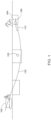
Fig. 4 is a side elevation view of the drill string starter rod for use in making the joint ofFigs. 2-3 . -
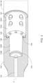
Fig. 4A is a perspective view looking into the drill head-facing end of the drill string starter rod. -
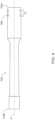
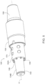
Fig. 5 is a perspective view of an adapter or coupler used in the joint ofFigs. 2-3 . -
Fig. 6 an end view of the joint ofFigs. 2 and3 . -
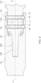
Fig. 7 is a cross-section view of the joint, taken along line 7-7 ofFig. 6 , which intersects a central axis of the drill string. -
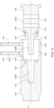
Fig. 8 is a cross-section view of the joint, taken along line 8-8 ofFig. 6 , which is offset from the central axis of the drill string to cut through a connection pin. -
Fig. 9 is a cross-section view of the joint, similar toFig. 8 , showing the various parts exploded rather than assembled. -
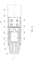
Fig. 10 is a cross-section view of the joint, similar toFig. 7 , showing an exaggerated clearance between a first insertion portion of the coupler and a first receiving bore of the starter rod. -
Fig. 11 is a cross-section view of the joint, taken along line 11-11 ofFig. 8 , to better illustrate a clearance between a cross pin and a bore within the first insertion portion of the coupler. -
Fig. 11A is a cross-section view similar toFig. 11 , but illustrating an alternate embodiment in which the bore within the first insertion portion is elongated circumferentially. -
Fig. 12 is a cross-section view of a drill string joint according to another embodiment of the present disclosure. -
Fig. 13 is a cross-section view, similar toFig. 7 , of a drill string joint according to another embodiment of the present disclosure. -
Fig. 14 is a cross-section view of the drill string joint ofFig. 13 , taken alone line 14-14. -
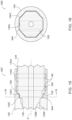
Fig. 15 is a cross-section view, similar toFig. 7 , of a drill string joint according to another embodiment of the present disclosure. -
Fig. 16 is a cross-section view of the drill string joint ofFig. 15 , taken alone line 16-16. - Before any embodiments of the present invention are explained in detail, it is to be understood that the invention is not limited in its application to the details of construction and the arrangement of components set forth in the following description or illustrated in the following drawings. The invention is capable of other embodiments and of being practiced or of being carried out in various ways.
-
Fig. 1 illustrates a basic system for horizontal directional drilling (HDD), including aHDD machine 100 operable to perform trenchless, directional-controlled underground drilling between two points, e.g., for utility installations, such as gas lines. A plurality of drill rod assemblies are sequentially connected end-to-end on theHDD machine 100 to form adrill string 102. Thedrill string 102 is driven into the ground by theHDD machine 100. At the end of thedrill string 102 is adrill head 104 having a rotating drilling tool ordrill bit 106. Thedrill head 104 can also include asonde housing 110 in which electronics (e.g., gyroscopic sensor(s), a data relay receiver, a beacon, a steering mechanism) are provided for tracking and/or steering thedrill head 104 underground. For example, thedrill head 104 may be steered around or under anunderground obstruction 108, e.g., a pre-existing sewer line or other utility installation, from above ground using information provided from the electronics in thesonde housing 110. TheHDD machine 100 includes a plurality of mechanical systems operable to assemble and disassemble adrill string 102 and operable to plunge and retract thedrill string 102 into and out of the ground in a direction that is at least partially horizontal with respect to the ground. - As shown in
Fig. 2 , an improved drill string joint 120 is provided for joining drill string components along an axis A. The drill string joint 120 can be provided, for example between thedrill head 104 and astarter rod 124.Fig. 2A illustrates the same joint 120 where thedrill head 104 is removed and replaced with areamer 126. Numerous drill rods, generally of uniform construction different than thestarter rod 124, are provided behind thestarter rod 124 to sequentially build up the length of thedrill string 102. In order to connect thestarter rod 124 with thesonde housing 110, the joint 120 includes aninterstitial coupler 128, which may be referred to as an adapter. Theinterstitial coupler 128 can have a first end (Fig. 2 , right) with a connection structure, for example by mating threads, securely coupled with thesonde housing 110. In the illustrated construction, thecoupler 128 has a taperedmale thread portion 130 that fits within a female thread portion of thesonde housing 110. However, it should be appreciated that other means of connection to thesonde housing 110 are optional, and that features at the second end (Fig. 2 , left) of theinterstitial coupler 128 can be provided on thesonde housing 110 as an integral part thereof. Further still, the drill string joint 120 may be used for other couplings besides those between thesonde housing 110 and thestarter rod 124. In generalized terms, thestarter rod 124 serves as a box-end member of the joint 120, and thecoupler 128 serves as a complementary, mating pin-end member of the joint 120. Thus, in the following description of thestarter rod 124 and thecoupler 128, it should be appreciated that features of these members are provided in order to achieve a specific joint construction between a box-end member and a pin-end member and they are not necessarily dependent in all constructions on being incorporated in a starter rod and coupler, per se. BeyondFig. 2 , the discussion focuses on the detailed construction of the joint 120. - As will become apparent from the further description below, the joint 120 is specifically constructed as a collar-less joint that provides drastic improvements in durability by divorcing from each other the sections of the coupling responsible for handling the bending loads and the longitudinal or axial push/pull loads, respectively. As a general introduction to the features described below,
Fig. 3 illustrates how thecoupler 128 is constructed with afirst section 134 of relatively larger diameter (e.g., equal to an outer diameter of thestarter rod 124 at the mating end), a first reduced-diameter section 134A and a further-reduced-diameter section 134B. As better shown inFig. 5 , thefirst section 134 of thecoupler 128 can in some constructions include portions of separate diameter, e.g., one portion generally matching the outer diameter of thestarter rod 124 and one portion generally matching the outer diameter of the distal end component (sonde housing 110 or reamer 126) coupled at the other end of thecoupler 128. The first reduced-diameter section 134A defines a first insertion portion that is received within afirst bore 136A of thestarter rod 124, while the further-reduced-diameter section 134B defines a second insertion portion received within asecond bore 136B of thestarter rod 124. The two reduced-diameter sections shoulder surface 138 is defined between the two reduced-diameter sections shoulder surface 138 is provided at the distal end of the first reduced-diameter section 134A. As illustrated, theshoulder surface 138 extends perpendicular to the axis A such that there is minimal or no axial spacing distance between the two reduced-diameter sections - The first reduced-
diameter section 134A and thefirst bore 136A define a first joint section responsible for carrying all the longitudinal, or particularly axial pullback loads, imparted during reaming or pullback operations of the horizontal directional drilling system. For example, all the forward drilling loads (i.e., drill string compression during pilot hole formation) between thestarter rod 124 and thecoupler 128 can be carried by theshoulder surface 138, which bears against another shoulder surface 160 (Fig. 4A ) on thestarter rod 124. Meanwhile, all the pullback loads (i.e., drill string tension during back reaming) between thestarter rod 124 and thecoupler 128 can be carried by a series ofcross-pins 140 that extend through both thestarter rod 124 and thecoupler 128 perpendicular to the axis A. The further-reduced-diameter section 134B and thesecond bore 136B define a second joint section responsible for carrying the bending loads imparted during the horizontal directional drilling operations. Atorque coupling 144 for transmitting torque between thestarter rod 124 and the coupler 128 (in either direction, depending upon circumstance) is defined at an end of the first reduced-diameter section 134A that is situated adjacent the bottom of thefirst bore 136A and adjacent the further-reduced-diameter section 134B. Adjacent the bottom end of thesecond bore 136B, a seal can be made between thestarter rod 124 and thecoupler 128, for example by an O-ring 150 at the distal end of the further-reduced-diameter section, or "nose"portion 134B of thecoupler 128. Alternately or in addition, a seal can be established at the open end of thefirst bore 136A or along the first reduced-diameter section 134A. An engagement length LB of thenose portion 134B can refer to the axial length of contact with thesecond bore 136B, either with or without theseal 150. - Turning briefly to the construction of the
starter rod 124 as shown by itself inFig. 4 and4A , it will be seen that thefirst end 124A of thestarter rod 124 defining thefirst bore 136A can have an outside surface that serves as a largest outer diameter portion of thestarter rod 124 along its axial length. The majority of the length of thestarter rod 124 has a uniform minimum outer diameter that is less than the outer diameter adjacent thefirst end 124A and less than an outer diameter adjacent a secondopposite end 124B. However, the diameter at thesecond end 124B is based on the particular connection size selected. Along the center of thestarter rod 124, an axial throughbore 152 is provided (Figs. 3 and4A ), rendering the starter rod hollow, e.g., for passage of drilling fluid during operation. As best shown inFig. 4A , the wall section bounding thefirst bore 136A and providing the large outer diameter periphery of thestarter rod 124 is provided with a plurality ofcross apertures 156 that are provided in pairs for respectively receiving the opposing ends of the respective cross-pins 140 for establishing the axial (pull) connection of the joint 120. Beyond thefirst bore 136A, thesecond bore 136B extends with a tapered profile such that thesecond bore 136B has a conical shape complementary to a conical outer surface shape of thenose portion 134B of thecoupler 128. Thesecond bore 136B extends to a depth approximately equal to a depth of thefirst bore 136A, and bothbores starter rod 124 as shown inFig. 3 . - As shown in
Fig. 4A , the transition between the first andsecond bores shoulder surface 160 at which the torque-coupling 144 is provided. Theshoulder surface 160 can be a ring-shaped surface lying in a plane perpendicular to the axis A and positioned at the respective ends of the first andsecond bores structures 162 are provided around theshoulder surface 160. As shown, thestructures 162 are blind bores of circular cross-section, although other shapes or constructions are optional. The blind bores 162 receive respective torque pins 166 that are also fixed with thecoupler 128 as described further below. In some constructions, there are more than fourtorque pins 166, e.g., at least 6, at least 7, or at least 8 torque pins 166. The torque pins 166, along with the correspondingbores 162, are equally spaced along the circumferential direction about the axis A. Each of the torque pins 166 can be press fit to one of thestarter rod 124 or thecoupler 128. In one exemplary construction, all the torque pins 166 are press fit to respective bores 168 (Fig. 9 ) in theshoulder surface 138 of thecoupler 128 that faces theshoulder surface 160 at the bottom of thefirst bore 136A. Thus, all the torque pins 166 remain with thecoupler 128 when the joint 120 is disassembled. When the joint 120 is assembled, thecoupler 128 may or may not contact theshoulder surface 160, depending upon the presence of axial load, but the torque pins 166 establish a torque transmitting connection with little or no rotational slack or backlash. The length of the torque pins 166 is selected so that they are short enough to avoid exposure to bending load and long enough that there is adequate surface area to avoid premature wear in theblind holes 162 on thestarter rod 124. - Turning to
Figs. 8 and9 , it can be seen that the cross pins 140 extend throughcorresponding apertures 170 in thecoupler portion 134A, which apertures 170 are aligned with corresponding ones of theapertures 156. Despite the substantial length LB (e.g., equal to or greater than the depth D1 of thefirst bore 136A,Fig. 7 ), thenose portion 134B does not bottom out in thesecond bore 136B, instead remaining spaced from abottom end 172 of thesecond bore 136B, ensuring that theapertures 170 can be put into alignment with the correspondingapertures 156 for assembly of the cross pins 140. Similarly, a space S may be left between the starter rodfirst end 124A and the first (large OD)section 134 of thecoupler 128 as shown inFig. 7 . Clearance between theapertures 170 and the outer diameter of the cross pins 140 (Figs. 8 and11 ), along with the substantial span of thenose portion 134B and the tight-fitting torque pins 166, isolates the cross pins 140 and the corresponding sections of thestarter rod 124 and thecoupler 128 from being exposed to torque or bending loads of the drill string. This especially increases the long-term durability of the starter rod wall section having thecross apertures 156. The cross pins 140 can be tight fitting, for example defining an interference fit, with thecross apertures 156 of thestarter rod 124. The clearance between the cross pins 140 and theapertures 170 through thecoupler 128 can be provided by simply oversizing the aperture 170 (e.g., circular) as shown inFig. 11 . An exemplary diametrical clearance here may be 0.020 inch to 0.060 inch. Alternately, as shown in the alternate embodiment ofFig. 11A , theapertures 170 may be circumferentially elongated (e.g., in addition to having an axially-measured diametrical clearance), providing them with a non-circular cross-section. The circumferential elongation can be 0.008 inch, or even substantially larger. BothFigs. 11 and 11A illustrate the cross pins 140 in a position within theaperture 170 that may be occupied during times of drill string tension (e.g., pullback). Although there may be particular advantage with providing the cross pins 140 with clearance on theapertures 170 and tight fit with theapertures 156, it is contemplated that this may also be reversed. - Although the mating surfaces of the
second bore 136B and thenose portion 134B are tapered (e.g., draft angle of 5 degrees or less) and tight fitting, there is no such relationship between the outside surface of thefirst insertion section 134A of thecoupler 120 and the directly adjacent inner surface of thefirst bore 136A. Each of these surfaces can be cylindrical in shape such that the surface extends parallel to the axis A. Furthermore, the joint 120 is designed with a built-in diametrical clearance between thefirst bore 136A and thefirst insertion section 134A. This small diametrical clearance (e.g., greater than 0.010 inch and less than 0.100 inch) is exaggerated inFig. 10 for illustrative purposes and results in the illustrated radial gap G. In a condition where thefirst insertion section 134A is centered in thefirst bore 136A, the diametrical clearance will be two times the radial gap G. In some constructions the diametrical clearance is 0.014 inch to 0.025 inch, or more particularly 0.018 inch to 0.021 inch. - To further characterize the various portions of the joint 120, the
nose portion 134B andsecond bore 136B are engaged along the length LB to bear bending loads in isolation (i.e., little or no torque or axial loads). The span of the engagement length LB is completely separate and spaced from a second axial span LA of the joint 120 in which the cross pins 140 reside (Fig. 8 ). The second axial span LA is a subset or central range within the depth D1 of thefirst bore 136A. The cross pins 140 also engage a portion of thecoupler 128 that is distinct from thenose portion 134B, i.e., thefirst insertion section 134A, which has a different outer diameter (and different shape) than thenose portion 134B. As described above, the axial span of the joint 120 in which the cross pins 140 are located is adapted to bear axial pullback loads in isolation (i.e., little or no torque or bending loads). Relatively speaking, thetorque coupling 144 is provided axially between the two aforementioned sections of the joint 120 (e.g., at the change in cross-section shape between thecoupler sections sections torque coupling 144 is generally incapable of bearing axial push/pull loads. Bending loads within thetorque coupling 144 are eliminated or limited by the presence of the extendedlength nose portion 134B, which is provided for this designated purpose. The engagement length LB may exceed an axial length of the torque pins 166 by a substantial margin. For example, the engagement length LB along thenose portion 134B may be at least 3 times or at least 4 times the torque pin length. The engagement length LB may be selected relative to the clearance between thefirst bore 136A and correspondingfirst insertion section 134A (i.e., the gap G) and/or the span of the first bore depth D1 where bending is desired to be avoided. For example, engagement length LB may be greater than the depth D1, e.g., with the exemplary clearance ranges stated above. -
Fig. 12 illustrates an alternate embodiment for a drill string joint 220 that is similar in most respects to the joint 120, but in which the box end member of the joint is formed by atube 232 welded or otherwise fixed to the first end of thestarter rod 124. In the illustrated construction, thetube 232 is secured to thestarter rod 124, which by itself does not form the hollow box end shape for thefirst insertion section 134A, by aweld bead 238 extending circumferentially partially or fully along an end of thetube 232. Thus, thefirst bore 136A (withcross apertures 156 therethrough) is formed by thetube 232, which extends axially outward from thefirst end 124A of thestarter rod 124. Thesecond bore 136B that receives thenose portion 134B extends directly to thefirst end 124A of thestarter rod 124, thefirst end 124A being the exposed distal end up until the time of creating the weldment with thetube 232. Thetube 232 can have a smooth, continuous inner cylindrical surface or may have a step formed therein at the axial position of thefirst end 124A of thestarter rod 124. Thetorque coupling 244 is formed at the first end of thestarter rod 124, which corresponds functionally to theshoulder surface 160 of thestarter rod 124 in the joint 120. This construction technique allows for machined splines/teeth in the matingjoint components torque coupling 244 directly, without the use of additional torque transmitting components therebetween (e.g., torque pins 166). The toothed profile can be cut into thecoupler 128 with an end-mill. A corresponding toothed profile can be cut into thestarter rod 124. Subsequent to the machining, thetube 232 is welded on so that the welded assembly becomes the box-end member to render the joint 220 functional in the manner described above with respect to the joint 120. It is also noted thatFig. 12 illustrates an alternate axial location for the O-ring 150, along thefirst insertion section 134A between thetorque coupling 244 and the cross pins 140. -
Figs. 13 and 14 illustrate another alternate embodiment for a drill string joint 320 that is similar in most respects to thejoints torque coupling 344 provided at an outer peripheral surface of thefirst insertion section 134A. Thetorque coupling 344 remains at the axial location of theshoulder surface 160 of thestarter rod 124 and the facingshoulder surface 138 of thecoupler 128. Unlike the construction in the joint 120 (seeFig. 7 ) where the torque pins 166 are entirely inside the outer profile (e.g., diameter) defined by thefirst insertion section 134A, the torque pins 166 in the joint 320 ofFigs. 13 and 14 are positioned to intersect the outer profile (e.g., diameter) defined by thefirst insertion section 134A. Some or all of the torque pins 166 are press fit to therespective bores 162 in theshoulder surface 160 at the bottom of thefirst bore 136A of thestarter rod 124. Thus, the torque pins 166 may remain with thestarter rod 124 when the joint 320 is disassembled. At the other axial end, the torque pins 166 are received partially inreceptacles 368 formed in the outer peripheral surface of thefirst insertion section 134A of thecoupler 128. Thereceptacles 368 can be troughs or cutouts, open to the radial outer side, rather than receptacles in the form of full-section blind bores as in the preceding joint embodiments. -
Figs. 15 and 16 illustrate yet another alternate embodiment for a drill string joint 420 that is similar in most respects to thejoints torque coupling 444 provided (e.g., directly) by complementary non-circular or polygonal cross-section profiles of anintermediate insertion section 134C of thecoupler 128 and anintermediate bore 136C of thestarter rod 124. In the illustrated construction, theintermediate insertion section 134C is a reduced-diameter section smaller than thefirst insertion portion 134A and larger than thesecond insertion section 134B. Likewise, theintermediate bore 136C is sized smaller than thefirst bore 136A and larger than thesecond bore 136B. In the illustrated construction, the cross-section profiles of theintermediate insertion section 134C and theintermediate bore 136C are octagonal. On this or other non-circular cross-section shapes, the diameter of the profiles making thetorque coupling 444 can be taken as the maximum dimension perpendicular to and through the axis A, or the diameter of a reference circle circumscribed through the point(s) farthest from the axis A. Points or surfaces of contact between theintermediate insertion section 134C and theintermediate bore 136C serve as torque connection structures that transmit torque therebetween, even without separate torque transmitting elements (e.g., pins 166). - A radial clearance gap is provided between the
intermediate insertion section 134C and theintermediate bore 136C when theintermediate insertion section 134C is centered in theintermediate bore 136C. Thus, a tight fit, which would promote the carrying of bending loads, is avoided, and thetorque coupling 444 operates to carry torque loads in isolation (i.e., little or no bending or axial loads). Theshoulder surface 138 facing theshoulder surface 160 of the starter rod 124 (and abutting to transmit axial drilling loads) is formed by the axial end surface of theintermediate insertion section 134C rather than the axial end surface of thefirst insertion section 134A. Thestarter rod 124 can be provided with an additional shoulder surface 160' radially outside theshoulder surface 160. An axial end surface 138' of thefirst insertion section 134A can directly face the additional shoulder surface 160', although an axial assembly clearance can be maintained therebetween. As illustrated, the joint 420 provides three completely discrete, non-overlapping, axial sections for carrying the bending loads, the torque loads, and the axial pullback loads, respectively. - Changes may be made in the above methods and systems without departing from the scope hereof. Also, aspects of various embodiments may be combined unless expressly prohibited. It should thus be noted that the matter contained in the above description or shown in the accompanying drawings should be interpreted as illustrative and not in a limiting sense. The following clauses are intended to cover all generic and specific features described herein, as well as all statements of the scope of the present method and system, which, as a matter of language, might be said to fall therebetween.
- When used in this specification and claims, the terms "comprises" and "comprising" and variations thereof mean that the specified features, steps or integers are included. The terms are not to be interpreted to exclude the presence of other features, steps or components.
- The features disclosed in the foregoing description, or the following claims, or the accompanying drawings, expressed in their specific forms or in terms of a means for performing the disclosed function, or a method or process for attaining the disclosed result, as appropriate, may, separately, or in any combination of such features, be utilised for realising the invention in diverse forms thereof.
- Preferred features of the invention are set out in the following clauses.
- The following claims are intended to cover all generic and specific features described herein, as well as all statements of the scope of the present method and system, which, as a matter of language, might be said to fall therebetween.
-
- 1. A drill string joint for joining a drill head to a drill string along a central axis, the joint comprising:
- a box end member defining, at a first axial end thereof, a first bore and a second deeper bore of smaller cross section than the first bore;
- a pin end member defining a first insertion portion corresponding to the first bore and a second insertion portion corresponding to the second bore, wherein a conical tapered surface interface is defined between the second insertion portion and the second bore;
- a plurality of cross pins extending through corresponding apertures formed through both the box end member, at the first bore, and the first insertion portion of the pin end member, the plurality of cross pins being located within a first axial span of the joint separate from a second axial span in which the conical tapered surface interface of the second insertion portion and the second bore is defined; and
- a torque coupling established between the box end member and the pin end member at an axial position between the first axial span and the second axial span.
- 2. The drill string joint of clause 1, wherein a diametrical clearance is provided between the first insertion portion and the first bore along the first axial span of the joint.
- 3. The drill string joint of clause 2, wherein the diametrical clearance is greater than 0.010 inch and less than 0.100 inch.
- 4. The drill string joint of clause 2, wherein the diametrical clearance is 0.018 inch to 0.021 inch.
- 5. The drill string joint of clause 1, wherein the plurality of cross pins are sized to fit loosely in the corresponding apertures of the pin end member and fit tightly in the corresponding apertures of the box end member.
- 6. The drill string joint of clause 1, wherein the plurality of cross pins includes four cross pins, all of which extend parallel to each other.
- 7. The drill string joint of clause 1, wherein the torque coupling includes a plurality of torque pins axially insertable into a plurality of blind bores provided in a circumferential array along a shoulder surface formed at the bottom of the first bore within the box end member.
- 8. The drill string joint of
clause 7, wherein the plurality of torque pins are press-fit to the pin end member. - 9. The drill string joint of clause 1, wherein the conical tapered surface interface between the second insertion portion and the second bore bears drill string bending loads in isolation, the conical tapered surface interface inhibiting the drill string bending loads from being borne by the first axial span and the torque coupling.
- 10. The drill string joint of clause 1, wherein the second axial span corresponding to the conical tapered surface interface between the second insertion portion and the second bore has a length greater than a length of the first axial span containing the plurality of cross pins.
- 11. The drill string joint of clause 1, wherein the joint provides three completely discrete, non-overlapping, axial sections for carrying the bending loads, the torque loads, and the axial pullback loads, respectively.
- 12. The drill string joint of clause 1, wherein the torque coupling is established by a plurality of torque pins positioned at least partially outside an outer profile defined by the first insertion portion.
- 13. The drill string joint of clause 1, wherein the torque coupling is established by complementary non-circular or polygonal cross-section profiles of an intermediate insertion portion of the pin end member between the first and second insertion portions.
- 14. A horizontal directional drilling system comprising:
- a horizontal directional drilling machine;
- a drill string terminating at a drill head and configured to be driven by the horizontal directional drilling machine to create an underground borehole extending at least partially horizontally between an entry point and an exit point; and
- the drill string joint of clause 1.
- 15. A method of assembling a drill string with a drill head along a central axis, the method comprising:
- inserting a pin end member into a box end member along the central axis such that a first insertion portion of the pin end member is positioned within a first bore of the box end member at a first axial end of the box end member, and a second insertion portion of the pin end member is positioned within a second deeper bore of the box end member, the second bore having a smaller cross section than the first bore;
- establishing a conical tapered surface interface between the second insertion portion and the second bore with the axial insertion of the pin end member to the box end member;
- establishing a torque coupling with the axial insertion of the pin end member to the box end member; and
- inserting a plurality of cross pins perpendicular to the central axis through corresponding apertures formed through both the box end member, at the first bore, and the first insertion portion of the pin end member, the plurality of cross pins being located within a first axial span of the joint separate from a second axial span in which the conical tapered surface interface is established,
- wherein the torque coupling is established at an axial position between the first axial span and the second axial span.
- 16. The method of clause 15, wherein the insertion of the pin end member into the box end member to establish the conical tapered surface interface and the torque coupling leaves a diametrical clearance of at least 0.010 inch between the first insertion portion and the first bore along the first axial span of the joint.
- 17. The method of clause 15, wherein the insertion of the plurality of cross pins includes passing each of the plurality of cross pins, with clearance, through the corresponding aperture of the pin end member and engaging the cross pin tightly in the corresponding aperture of the box end member.
- 18. The method of clause 15, wherein the insertion of the plurality of cross pins includes inserting four cross pins, all along parallel insertion directions.
- 19. The method of clause 15, wherein the establishment of the torque coupling includes insertion of a plurality of torque transmitting elements, in the form of a plurality of torque pins, into a plurality of blind bores provided in a circumferential array along a shoulder surface formed at the bottom of the first bore within the box end member.
- 20. The method of clause 19, further comprising press-fitting the plurality of torque pins to the pin end member prior to the insertion.
- 21. The method of clause 15, wherein the conical tapered surface interface is established along the second axial span to define a length exceeding a length of the first axial span.
- 22. The method of clause 15, wherein the box end member is provided at a first end of a starter rod of the drill string, the method further comprising coupling a first drill rod to a second end of the starter rod, and coupling the drill head to the pin end member.
- 23. The method of clause 15, further comprising leaving the outside surfaces of the pin end member and the box end member exposed at the joint, free of any separate collar device.
- 24. The method of clause 15, wherein the axial position of the torque coupling is completely discrete and not overlapping with the first and second axial spans such that separate axial sections are provided for carrying the bending loads, the torque loads, and the axial pullback loads, respectively.
- 25. The method of clause 15, wherein the torque coupling is established by a plurality of torque pins positioned at least partially outside an outer profile defined by the first insertion portion.
- 26. The method of clause 15, wherein the torque coupling is established by complementary non-circular or polygonal cross-section profiles of an intermediate insertion portion of the pin end member between the first and second insertion portions.
- 27. A drill string coupler for establishing a joint between drill string components at a head end of a drill string of a horizontal directional drilling system, the coupler comprising:
- a first coupling portion adapted for insertion into a first bore along a central axial direction;
- a second coupling portion having a conical tapered surface adapted for insertion into a second bore smaller than the first bore, wherein the second coupling portion is provided along an axial span that is offset from an axial span of the first coupling portion;
- a plurality of cross apertures formed through the first coupling portion to receive a corresponding plurality of cross pins; and
- a torque connection structure provided at an axial position between the respective axial spans of the first and second connection portions.
- 28. The drill string coupler of clause 27, further comprising a third coupling portion provided at an end opposite an end of the coupler defining the second coupling portion, the third coupling portion provided in an axial span that is offset from the respective axial spans of the first and second connection portions.
- 29. The drill string coupler of clause 27, wherein the axial position of the torque connection structure is completely discrete and not overlapping with the first and second axial spans such that separate axial sections are provided for carrying the bending loads, the torque loads, and the axial pullback loads, respectively.
- 30. The drill string coupler of clause 27, wherein the torque connection structure is established by a plurality of receptacles configured to receive torque connection pins at least partially outside an outer profile defined by the first insertion portion.
- 31. The drill string coupler of clause 27, wherein the torque connection structure is established by a non-circular or polygonal cross-section profile of an intermediate insertion portion between the first and second insertion portions.
Claims (15)
- A drill string coupler for establishing a joint between drill string components at a head end of a drill string of a horizontal directional drilling system, the coupler comprising:a first coupling portion adapted for insertion into a first bore along a central axial direction;a second coupling portion having a conical tapered surface adapted for insertion into a second bore smaller than the first bore, wherein the second coupling portion is provided along an axial span that is offset from an axial span of the first coupling portion;a plurality of cross apertures formed through the first coupling portion to receive a corresponding plurality of cross pins; anda torque connection structure provided at an axial position between the respective axial spans of the first and second connection portions.
- The drill string coupler of claim 1, further comprising a third coupling portion provided at an end opposite an end of the coupler defining the second coupling portion, the third coupling portion provided in an axial span that is offset from the respective axial spans of the first and second connection portions.
- The drill string coupler of claim 1, wherein the axial position of the torque connection structure is completely discrete and not overlapping with the first and second axial spans such that separate axial sections are provided for carrying the bending loads, the torque loads, and the axial pullback loads, respectively.
- The drill string coupler of claim 1, wherein the torque connection structure is established by a plurality of receptacles configured to receive torque connection pins at least partially outside an outer profile defined by the first insertion portion.
- The drill string coupler of claim 1, wherein the torque connection structure is established by a non-circular or polygonal cross-section profile of an intermediate insertion portion between the first and second insertion portions.
- The drill string coupler of claim 1, wherein the torque connection structure includes a plurality of torque pins press fit to respective bores in a shoulder surface defined between the first coupling portion and the second coupling portion.
- The drill string coupler of claim 6, wherein the plurality of torque pins define a torque pin length, and an engagement length of the second coupling portion is at least three times the torque pin length.
- The drill string coupler of claim 7, wherein the engagement length of the second coupling portion is at least four times the torque pin length.
- The drill string coupler of claim 6, wherein the plurality of torque pins comprises more than four torque pins.
- The drill string coupler of claim 1, wherein each one of the plurality of cross apertures has a circular cross-section.
- The drill string coupler of claim 1, wherein each one of the plurality of cross apertures has a non-circular cross-section that is circumferentially elongated.
- The drill string coupler of claim 1, further comprising an O-ring at a distal end of the second coupling portion.
- The drill string coupler of claim 1, wherein the plurality of cross apertures extend through the coupler perpendicular to the central axial direction.
- The drill string coupler of claim 1, wherein the torque connection structure comprises machined splines or teeth, the drill string coupler further comprising an O-ring positioned along the first coupling portion between the torque connection structure and the plurality of cross apertures.
- The drill string coupler of claim 1, wherein the second coupling portion has a draft angle of 5 degrees or less to form the conical tapered surface.
Applications Claiming Priority (3)
| Application Number | Priority Date | Filing Date | Title |
|---|---|---|---|
| US202063057562P | 2020-07-28 | 2020-07-28 | |
| PCT/US2021/042435 WO2022026252A1 (en) | 2020-07-28 | 2021-07-20 | Drill string joint for horizontal directional drilling system |
| EP21752835.5A EP4189204B1 (en) | 2020-07-28 | 2021-07-20 | Drill string joint for horizontal directional drilling system |
Related Parent Applications (2)
| Application Number | Title | Priority Date | Filing Date |
|---|---|---|---|
| EP21752835.5A Division EP4189204B1 (en) | 2020-07-28 | 2021-07-20 | Drill string joint for horizontal directional drilling system |
| EP21752835.5A Division-Into EP4189204B1 (en) | 2020-07-28 | 2021-07-20 | Drill string joint for horizontal directional drilling system |
Publications (3)
| Publication Number | Publication Date |
|---|---|
| EP4353943A2 true EP4353943A2 (en) | 2024-04-17 |
| EP4353943A3 EP4353943A3 (en) | 2024-05-22 |
| EP4353943B1 EP4353943B1 (en) | 2026-05-06 |
Family
ID=77301024
Family Applications (2)
| Application Number | Title | Priority Date | Filing Date |
|---|---|---|---|
| EP21752835.5A Active EP4189204B1 (en) | 2020-07-28 | 2021-07-20 | Drill string joint for horizontal directional drilling system |
| EP24160055.0A Active EP4353943B1 (en) | 2020-07-28 | 2021-07-20 | Drill string joint for horizontal directional drilling system |
Family Applications Before (1)
| Application Number | Title | Priority Date | Filing Date |
|---|---|---|---|
| EP21752835.5A Active EP4189204B1 (en) | 2020-07-28 | 2021-07-20 | Drill string joint for horizontal directional drilling system |
Country Status (6)
| Country | Link |
|---|---|
| US (1) | US12264543B2 (en) |
| EP (2) | EP4189204B1 (en) |
| CN (1) | CN116157583A (en) |
| AU (1) | AU2021318870B2 (en) |
| CA (1) | CA3187227A1 (en) |
| WO (1) | WO2022026252A1 (en) |
Families Citing this family (1)
| Publication number | Priority date | Publication date | Assignee | Title |
|---|---|---|---|---|
| CN121729548A (en) * | 2023-08-28 | 2026-03-24 | 维米尔制造公司 | Pilot bit assembly with separable drive coupling |
Citations (3)
| Publication number | Priority date | Publication date | Assignee | Title |
|---|---|---|---|---|
| US6766869B2 (en) | 1999-12-17 | 2004-07-27 | Vermeer Manufacturing Company | Remote lock-out system and method for a horizontal directional drilling machine |
| US20130084131A1 (en) | 2010-12-01 | 2013-04-04 | Vermeer Manufacturing Company | Tapered thread configuration with improved durability |
| EP3587729A1 (en) | 2018-06-22 | 2020-01-01 | TRACTO-TECHNIK GmbH & Co. KG | Connection of two drill string elements of a drill string for earth drilling |
Family Cites Families (8)
| Publication number | Priority date | Publication date | Assignee | Title |
|---|---|---|---|---|
| US6148935A (en) | 1998-08-24 | 2000-11-21 | Earth Tool Company, L.L.C. | Joint for use in a directional boring apparatus |
| US6860514B2 (en) | 2002-01-14 | 2005-03-01 | Earthjtool Company, L.L.C. | Drill string joint |
| US6810971B1 (en) * | 2002-02-08 | 2004-11-02 | Hard Rock Drilling & Fabrication, L.L.C. | Steerable horizontal subterranean drill bit |
| DE10359880B4 (en) * | 2003-12-18 | 2012-08-30 | Tracto-Technik Gmbh | Drill pipe system with a flexible bending element and method for optimized directional drilling |
| US8225885B2 (en) | 2008-05-01 | 2012-07-24 | Earth Tool Company, Llc | Joint for use in back reaming |
| US9206851B2 (en) | 2012-08-16 | 2015-12-08 | The Charles Machine Works, Inc. | Horizontal directional drill pipe drive connection with locking feature |
| US20140251694A1 (en) * | 2013-03-08 | 2014-09-11 | Earth Tool Company Llc | Directional Boring Tooling Reed Type Checkflow Valve |
| DE102019121054A1 (en) * | 2018-08-06 | 2020-02-06 | The Charles Machine Works, Inc. | Double-tube drill bit quick-change connection |
-
2021
- 2021-07-20 CA CA3187227A patent/CA3187227A1/en active Pending
- 2021-07-20 EP EP21752835.5A patent/EP4189204B1/en active Active
- 2021-07-20 AU AU2021318870A patent/AU2021318870B2/en active Active
- 2021-07-20 US US18/006,704 patent/US12264543B2/en active Active
- 2021-07-20 WO PCT/US2021/042435 patent/WO2022026252A1/en not_active Ceased
- 2021-07-20 CN CN202180059335.9A patent/CN116157583A/en active Pending
- 2021-07-20 EP EP24160055.0A patent/EP4353943B1/en active Active
Patent Citations (3)
| Publication number | Priority date | Publication date | Assignee | Title |
|---|---|---|---|---|
| US6766869B2 (en) | 1999-12-17 | 2004-07-27 | Vermeer Manufacturing Company | Remote lock-out system and method for a horizontal directional drilling machine |
| US20130084131A1 (en) | 2010-12-01 | 2013-04-04 | Vermeer Manufacturing Company | Tapered thread configuration with improved durability |
| EP3587729A1 (en) | 2018-06-22 | 2020-01-01 | TRACTO-TECHNIK GmbH & Co. KG | Connection of two drill string elements of a drill string for earth drilling |
Also Published As
| Publication number | Publication date |
|---|---|
| AU2021318870A1 (en) | 2023-05-18 |
| CA3187227A1 (en) | 2022-02-03 |
| AU2021318870B2 (en) | 2025-07-24 |
| EP4189204A1 (en) | 2023-06-07 |
| US20230272679A1 (en) | 2023-08-31 |
| EP4189204B1 (en) | 2024-06-19 |
| EP4353943A3 (en) | 2024-05-22 |
| US12264543B2 (en) | 2025-04-01 |
| EP4353943B1 (en) | 2026-05-06 |
| WO2022026252A1 (en) | 2022-02-03 |
| CN116157583A (en) | 2023-05-23 |
Similar Documents
| Publication | Publication Date | Title |
|---|---|---|
| US11015392B2 (en) | Dual member pipe joint for a dual member drill string | |
| US11098530B2 (en) | Dual rod directional drilling system | |
| US5908212A (en) | Ultra high torque double shoulder tool joint | |
| US5372208A (en) | Tube section having slots for sampling | |
| EP1200704B1 (en) | Threaded pipe connection | |
| US9038751B2 (en) | Down-hole hammer drill | |
| EP3143237B1 (en) | Joint and joint parts for drill string components | |
| US20010017222A1 (en) | Directional drilling components and adaptors | |
| EP0817901B1 (en) | Dual-member pipe joint for a dual member drill string | |
| CA2996718A1 (en) | Multi-lead quick connect threaded connection | |
| CN113614327A (en) | Rod coupler and coupling rod assembly | |
| AU2021318870B2 (en) | Drill string joint for horizontal directional drilling system | |
| US20230193701A1 (en) | Dual pipe drill head quick interchange joint | |
| WO2015179906A1 (en) | Drill pipe rod for air rotary drilling | |
| CN104160105A (en) | Reverse circulation bit assembly | |
| US20120043132A1 (en) | Reamer Assembly | |
| JPH06158976A (en) | Tube section and method of boring sampling well | |
| EP3788227B1 (en) | Downhole tool | |
| RU2323322C2 (en) | Connection device to connect two substantially rod-shaped or tubular members | |
| RU2269639C1 (en) | Clutch coupling for drill rods | |
| WO1997026437A1 (en) | Threaded joint |
Legal Events
| Date | Code | Title | Description |
|---|---|---|---|
| PUAI | Public reference made under article 153(3) epc to a published international application that has entered the european phase |
Free format text: ORIGINAL CODE: 0009012 |
|
| STAA | Information on the status of an ep patent application or granted ep patent |
Free format text: STATUS: THE APPLICATION HAS BEEN PUBLISHED |
|
| REG | Reference to a national code |
Ref country code: DE Free format text: PREVIOUS MAIN CLASS: E21B0017040000 Ipc: E21B0007040000 Ref country code: DE Ref legal event code: R079 Ref document number: 602021054190 Country of ref document: DE Free format text: PREVIOUS MAIN CLASS: E21B0017040000 Ipc: E21B0007040000 |
|
| AC | Divisional application: reference to earlier application |
Ref document number: 4189204 Country of ref document: EP Kind code of ref document: P |
|
| AK | Designated contracting states |
Kind code of ref document: A2 Designated state(s): AL AT BE BG CH CY CZ DE DK EE ES FI FR GB GR HR HU IE IS IT LI LT LU LV MC MK MT NL NO PL PT RO RS SE SI SK SM TR |
|
| PUAL | Search report despatched |
Free format text: ORIGINAL CODE: 0009013 |
|
| AK | Designated contracting states |
Kind code of ref document: A3 Designated state(s): AL AT BE BG CH CY CZ DE DK EE ES FI FR GB GR HR HU IE IS IT LI LT LU LV MC MK MT NL NO PL PT RO RS SE SI SK SM TR |
|
| RIC1 | Information provided on ipc code assigned before grant |
Ipc: E21B 17/04 20060101ALI20240412BHEP Ipc: E21B 23/02 20060101ALI20240412BHEP Ipc: E21B 17/046 20060101ALI20240412BHEP Ipc: E21B 7/04 20060101AFI20240412BHEP |
|
| STAA | Information on the status of an ep patent application or granted ep patent |
Free format text: STATUS: REQUEST FOR EXAMINATION WAS MADE |
|
| 17P | Request for examination filed |
Effective date: 20241118 |
|
| RBV | Designated contracting states (corrected) |
Designated state(s): AL AT BE BG CH CY CZ DE DK EE ES FI FR GB GR HR HU IE IS IT LI LT LU LV MC MK MT NL NO PL PT RO RS SE SI SK SM TR |
|
| GRAP | Despatch of communication of intention to grant a patent |
Free format text: ORIGINAL CODE: EPIDOSNIGR1 |
|
| STAA | Information on the status of an ep patent application or granted ep patent |
Free format text: STATUS: GRANT OF PATENT IS INTENDED |
|
| INTG | Intention to grant announced |
Effective date: 20251218 |
|
| GRAS | Grant fee paid |
Free format text: ORIGINAL CODE: EPIDOSNIGR3 |
|
| GRAA | (expected) grant |
Free format text: ORIGINAL CODE: 0009210 |
|
| STAA | Information on the status of an ep patent application or granted ep patent |
Free format text: STATUS: THE PATENT HAS BEEN GRANTED |
|
| AC | Divisional application: reference to earlier application |
Ref document number: 4189204 Country of ref document: EP Kind code of ref document: P |
|
| AK | Designated contracting states |
Kind code of ref document: B1 Designated state(s): AL AT BE BG CH CY CZ DE DK EE ES FI FR GB GR HR HU IE IS IT LI LT LU LV MC MK MT NL NO PL PT RO RS SE SI SK SM TR |
|
| REG | Reference to a national code |
Ref country code: CH Ref legal event code: F10 Free format text: ST27 STATUS EVENT CODE: U-0-0-F10-F00 (AS PROVIDED BY THE NATIONAL OFFICE) Effective date: 20260506 Ref country code: GB Ref legal event code: FG4D |