EP4353940A1 - Presentation sample of double-fabric product - Google Patents
Presentation sample of double-fabric product Download PDFInfo
- Publication number
- EP4353940A1 EP4353940A1 EP23000020.0A EP23000020A EP4353940A1 EP 4353940 A1 EP4353940 A1 EP 4353940A1 EP 23000020 A EP23000020 A EP 23000020A EP 4353940 A1 EP4353940 A1 EP 4353940A1
- Authority
- EP
- European Patent Office
- Prior art keywords
- fabric
- fold
- loose
- cuff
- sample
- Prior art date
- Legal status (The legal status is an assumption and is not a legal conclusion. Google has not performed a legal analysis and makes no representation as to the accuracy of the status listed.)
- Granted
Links
Images





Classifications
-
- E—FIXED CONSTRUCTIONS
- E06—DOORS, WINDOWS, SHUTTERS, OR ROLLER BLINDS IN GENERAL; LADDERS
- E06B—FIXED OR MOVABLE CLOSURES FOR OPENINGS IN BUILDINGS, VEHICLES, FENCES OR LIKE ENCLOSURES IN GENERAL, e.g. DOORS, WINDOWS, BLINDS, GATES
- E06B9/00—Screening or protective devices for wall or similar openings, with or without operating or securing mechanisms; Closures of similar construction
- E06B9/24—Screens or other constructions affording protection against light, especially against sunshine; Similar screens for privacy or appearance; Slat blinds
- E06B9/26—Lamellar or like blinds, e.g. venetian blinds
- E06B9/262—Lamellar or like blinds, e.g. venetian blinds with flexibly-interconnected horizontal or vertical strips; Concertina blinds, i.e. upwardly folding flexible screens
-
- G—PHYSICS
- G09—EDUCATION; CRYPTOGRAPHY; DISPLAY; ADVERTISING; SEALS
- G09F—DISPLAYING; ADVERTISING; SIGNS; LABELS OR NAME-PLATES; SEALS
- G09F5/00—Means for displaying samples
- G09F5/04—Cards of samples; Books of samples
-
- E—FIXED CONSTRUCTIONS
- E06—DOORS, WINDOWS, SHUTTERS, OR ROLLER BLINDS IN GENERAL; LADDERS
- E06B—FIXED OR MOVABLE CLOSURES FOR OPENINGS IN BUILDINGS, VEHICLES, FENCES OR LIKE ENCLOSURES IN GENERAL, e.g. DOORS, WINDOWS, BLINDS, GATES
- E06B9/00—Screening or protective devices for wall or similar openings, with or without operating or securing mechanisms; Closures of similar construction
- E06B9/24—Screens or other constructions affording protection against light, especially against sunshine; Similar screens for privacy or appearance; Slat blinds
- E06B9/26—Lamellar or like blinds, e.g. venetian blinds
- E06B9/262—Lamellar or like blinds, e.g. venetian blinds with flexibly-interconnected horizontal or vertical strips; Concertina blinds, i.e. upwardly folding flexible screens
- E06B2009/2627—Cellular screens, e.g. box or honeycomb-like
-
- G—PHYSICS
- G09—EDUCATION; CRYPTOGRAPHY; DISPLAY; ADVERTISING; SEALS
- G09F—DISPLAYING; ADVERTISING; SIGNS; LABELS OR NAME-PLATES; SEALS
- G09F5/00—Means for displaying samples
- G09F5/04—Cards of samples; Books of samples
- G09F2005/048—Cards of samples; Books of samples for fabrics
Definitions
- curtains and shades can be opened and closed.
- a particular class of curtains and shade are suspended at their upper side and are opened or closed by moving their lower side up or down.
- curtains and shades can generally be made from different kinds of materials.
- the invention relates generally to multi-layer fabric that can be used for curtains and shades of the type that are opened or closed by moving their lower side up or down.
- curtains and shades generally have large sizes, in the order of several meters. Retailers will be able to have a few real-size curtains and shades on display, but the number of available materials is very large, given all variations in patterns and colours. For consumers who wish to select a particular curtain or shade, it is desirable that product samples are available: small pieces of the actual material.
- the present invention relates particularly to product samples of double-fabric material. Since these samples are intended for presenting and showing to potentially interested persons, including potential customers, they will hereinafter be indicated as "presentation sample”.
- Figure 1A schematically shows a cross-section of a double-fabric material 1, in a condition when it is suspended from a support. The figure only shows a lower portion of the material.
- the material 1 has a vertical front face 2 and a vertical back face 3 defined by two different fabrics 4 and 5, respectively. These two fabrics may be of identical design and appearance, and may even be cut from the same base material, but in principle these two fabrics are of different design and appearance, and usually one of these fabric is a more decorative front while the other fabric, i.e. the back, is less visible in normal use.
- connection lines perpendicular to the plane of drawing.
- Such connection may be implemented by stitching the two fabrics 4 and 5 directly together, or, as shown, by connection bridges 6.
- connection bridges 6 define bottom wall and top wall of the tubes and the two fabrics 4 and 5 define side walls of the tubes.
- connection At the location of connection, the distance between the two fabrics 4 and 5 will always be the same.
- the connection bridges 6 move towards each other.
- the cell structure collapses, with the tube walls giving way by moving outwards. In doing so, the adjoining fabric portions of adjacent tubes hinge with respect to each other.
- the tube walls themselves may assume a semi-circular cross-sectional contour.
- the fabrics 4 and 5 are provided with predefined folds at mid-positions between the locations of connection.
- the double-fabric material 1 is made from pleated fabric, as will be explained in more detail.
- Pleated fabrics are generally made by folding a fabric in zigzag manner, also indicated as harmonica-style.
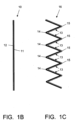
- Figure 1B shows a straight, unfolded piece of fabric 10
- figure 1C shows the fabric folded in zigzag manner, with always strips 13 of fabric meeting each other at folds 14, 15. This folded fabric will be indicated by reference numeral 16.
- Fabric typically has a front side 11 and a back side 12.
- the fabric is indicated by a double line, with the front side 11 indicated by a thick line and the back side 12 indicated by a thin line.
- the double line is not intended to indicate double layers of fabric.
- the front side 11 and back side 12 of the fabric 10 logically define a front side and back side of the folded fabric 16.
- Figure 1D schematically illustrates how a double-fabric material 1 can be made by attaching to each other two of such singular folded fabrics.
- the figure shows a first web of fabric 10 and a second web of fabric 20; for this second web, reference numerals are the same as for the first web 10, yet increased by 10.
- Each web 10, 20 is folded, and the two folded webs 16, 26 are arranged with their respective back sides 12, 22 facing each other.
- the folds 14, 24 where the front sides 11, 21 are at the outside of the fold are directed away from each other and will be indicated as outward folds or front folds.
- the folds 15, 25 where the back sides 12, 22 are at the outside of the fold are directed towards each other and will be indicated as inward folds or back folds.
- the two folded webs 16, 26 are attached together by stitching together the inward folds 15, 25.
- the two folded webs 16, 26 are partly inserted into each other, with the respective back inward folds 15, 25 partly overlapping each other at overlap regions 1727.
- the overlapping portions of fabric are attached to each other, possibly by stitching but typically by gluing, to form the connecting bridges 6.
- the resulting double-fabric material 1 has the appearance of tube-shaped material parts, also indicated as cells, stacked onto each other; these tube-shaped material parts will hereinafter be indicated by reference numeral 30.
- connecting bridges are made by providing separate strips of some material, that are attached to the respective inward folds 15, 25, such as to be able to obtain wider cells.
- the tube-shaped material parts 30 have an approximate hexagonal cross-section; depending on the stiffness of the fabric, the strips 13, 23 may typically have a somewhat S-shaped contour, as shown in figure 1E at a larger scale.
- Each individual cell can be described as having an upper wall 31 and a lower wall 32, and two folded side walls 33 and 34 with respective folds 35 and 36.
- the upper wall 31 and lower wall 32 are typically formed by the connecting bridges 6 where the overlapping fabric portions are attached to each other.
- the double-fabric material 1 has a collapsed condition in which the side walls 33 and 34 are folded back on themselves and the upper wall 31 and the lower wall 32 of the cells 30 are close together or even touch each other, in other words the cells 30 have respective height approximately equal to zero, as illustrated in figure 1F .
- the double-fabric material 1 has an extended condition in which the upper wall 31 and the lower wall 32 of the cells 30 are at large distance from each other and the side walls 33 and 34 are folded open, as illustrated in figure 1G .
- the cells 30 then may approximate a rectangular contour with substantially straight side walls 33 and 34. In practice, however, in the extended condition, the side walls 33 and 34 will more or less assume the shape of curly brackets.
- the original inward folds 15, 25 have now lost their function as folds, because the material portions immediately adjacent those folds are fixedly attached to each other.
- those material strips 13, 23 can hinge with respect to each other, and/or they can flex, depending on their stiffness.
- the front face 2 and the back face 3 consist of those portions of the material strips 13, 23 that are free from each other, and they are perceived as hinging with respect to each other; therefore, these meeting positions will be indicated as hinges 37, 38.
- the inner side of the fabric is the surface of the fabrics directed to the interior of the cells, which normally is the back side 12, 22 of the respective fabrics 10, 20.
- the outward-facing outer side of the fabrics is normally the front side 11, 21 of the respective fabrics 10, 20.
- both fabrics 10, 20 have appealing front sides 11, 21 such that the material can be used either way, particularly in its function as for instance a curtain or a screen
- the double-fabric material 1 may in principle be constructionally symmetrical
- the front side is of higher importance, both functionally and aesthetically, and for a presentation sample it is more important to show the front side rather than the back side.
- the front fabric 10 is shown in solid black while the back fabric 20 is shown in dotted grey.
- a piece of the double-fabric material 1 is taken and cut in parallel to the fold lines.
- the upper side of the cut product, in collapsed condition will be the visible presentation face of the sample. The result depends on the precise location of the cut line, as will be explained with reference to the embodiment discussed with reference to figures 1D-1G .
- Figure 2A shows an example where the cut (indicated by a dotted line) is made at a low level in a cell 30, just above the bottom wall 32 and below the respective outward folds 35, 36.
- the loose ends 8, 9 are the remaining small portions of the side walls 33, 34 extending away from the hinges 37, 38, which have their respective back sides facing upwards.
- the upper side of the cut product will then consist of the cell bottom wall 32 flanked by two loose ends 8, 9 which only show back side material. It is only outside those two loose ends 8, 9 that relative small portions of the respective front sides 2, 3 of the next cell are visible. This is not an appealing presentation.
- the width of those two loose ends 8, 9 reduces, and in theory it is possible to reduce this width to zero, but this requires a very accurate cutting process. But even then, at best, the visible presentation face of the sample will consist of the central glued cell bottom portion 32, with a small portion of the front side 41 material of the double-fabric material 1 on one side and an equally sized portion of the back side 42 material of the double-fabric material 1 on the opposite side.
- Figure 2B shows an example where the cut (indicated by a dotted line) is made at a high level in a cell 30, above the respective outward folds 35, 36.
- the cut edge is indicated by reference numerals 137, 138, respectively.
- the loose ends 8, 9 extend from the hinges 37, 38 to the cut edges 137, 138.
- the upper side of the cut product will then consist of those portions of the loose ends 8, 9 which extend between the respective outward folds 35, 36 and the cut edges 137, 138, which portions have their respective front sides 11, 21 facing upwards.
- the situation with the extreme highest cut position is worse than the situation with the extreme lowest cut position, because the loose ends 8, 9 are loose, allow the interior of the cell to be seen, and present raw edges 137, 138 of the fabric material.
- the masking strip M has the purpose of hiding the raw edges 137, 138 from view and can be used for the advantage of presenting text and other information.
- this masking strip M detracts from the ornamental value of the upper side of the sample, and further it hides a portion of the respective strips from view.
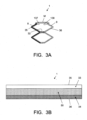
- Figure 3B shows a schematic top view of such sample, to illustrate that the visible top side of the sample basically consists of the masking strip M flanked by two small strips 33, 34 of fabric.
- the width of the masking strip M will be in the same order as the width of the material strips that are visible, while only one of those material strips is of actual interest as showing front side material while the other material strip in fact only shows the neutral backside of the product.
- An object of the present invention is to provide a presentation sample of a double-fabric material that shows a larger portion of the front side of the double-fabric material.
- Figure 4 is a schematic cross-section comparable to figure 2B , illustrating an important aspect of the present invention.
- the double-fabric product 1 has been cut at a relatively high level in an uppermost cell 30U, as in the case of figure 2B .
- the figure shows one whole cell 30 below the cut uppermost cell 30U, but the number of whole cells may in a practical sample be higher, typically in the order of ten.
- this loose end 8 now has a first fold 51 at a position lower than the original fold 35, close to the bottom wall 32 of the cut uppermost cell 30U, preferably directly adjacent this bottom wall 32 and coinciding with the hinge 37.
- This first fold 51 will also be indicated as proximal fold.
- this loose end 8 now has a second fold 52 at a position closer to the cut edge 137.
- This second fold 52 will also be indicated as distal fold.
- the first and second folds 51, 52 are folded in the same direction, namely with the front fabric side 11 at the outside of the folds.
- the proximal fold 51 can be distinguished from the hinge 37.
- the lower portion of the adjacent side wall 33 will in practice have a hinge range between 0° and 90°, i.e. it will make an angle of 0° with the cell bottom 32 in the collapsed condition and it will make an angle of not more than 90° with the cell bottom 32 in the extreme extended condition.
- the upper end of the hinge range will be lower than 90°, depending on material stiffness.
- the two material portions at opposite sides of the proximal fold 51 will in practice have a hinge range between 90° and 180°, i.e. they will make an angle of 180° with each other in the collapsed condition and they will make an angle of not less than 90° with the cell bottom 32 in the extreme extended condition.
- the lower end of the hinge range will be higher than 90°, depending on material stiffness.
- the distal fold 52 may in practice be constituted by the original fold 35, but the second fold 52 may also be a new fold positioned closer to the cut edge 137, in which case the original fold 35 may be flattened, or may still be recognized. In any case, the fabric portion between the second fold 52 and the cut edge 137 will be indicated as "cuff" 54.
- the material portion 53 between these two folds 51, 52 extends over the bottom wall 32 of the cut uppermost cell 30U, and substantially hides the opposite back side wall 34 from view.
- the top side of the resulting presentation sample 100 is visually almost entirely defined by said material portion 53 plus the adjacent upper half of the front side wall 33 of the next cell 30.
- said material portion 53 will be indicated as main sample face 53.
- the cells are shown in an open condition, but in the collapsed condition said main sample face 53 plus the upper half of the front side wall 33 of the next cell 30 will extend substantially in a same horizontal plane, said front side wall 33 of the next cell 30 making an angle of 0° with the bottom 32 and the main sample face 53 making an angle of 180° with the bottom 32.
- the cuff 54 with its raw edge 137 is hidden behind the main sample face 53, and the second fold 52 presents a neat finished edge for this main sample face 53.
- the second loose end 9 may be straight, because its raw edge 138 will be hidden from view by the covering main sample face 53, as illustrated by Figure 5A .
- the second loose end 9 may alternatively have a finishing front fold 61, where the fabric is folded upwards over 180°, i.e. with the front fabric side 21 at the outside of the finishing front fold 61.
- the finishing front fold 61 may be constituted by the original fold 36.
- the fabric portion between the finishing front fold 61 and the cut edge 138 will be indicated as "cuff" 62.
- the main sample face 53 may extend beyond this finishing front fold 61, like in figure 5A , but it is also possible to have a portion of the cuff 62 extend over a small distance beyond the second fold 52, as illustrated in figure 5B , to have the presentation sample 100 show a small strip of back side material.
- the cuff 54 of the loose end 8 may have the same length as the main sample face 53 and extend back up to the proximal fold 51, i.e. the distance between the edge 137 of the cuff 54 and the distal fold 52 may be equal to the distance between the proximal fold 51 and the distal fold 52.
- the distal fold 52 is constituted by the original fold 35 and the finishing front fold 61 is constituted by the original fold 36.
- the finishing front fold 61 is neatly aligned with the folds 36 of lower cells, and the distance between the edge 137 of the cuff 54 and the distal fold 52 is equal to the distance between the proximal fold 51 and the distal fold 52.
- the cuff 54 of the first loose end 8 may be folded around the second loose end 9, either as straight wall as in figure 5A , or as folded wall as in figure 5B .
- the cuff 54 of the first loose end 8 is attached to the cuff 62 of the second loose end 9, typically by gluing.
- the presentation sample 100 is provided with a manipulation card or strip attached to the fabric.
- manipulation card is made of a relatively stiff material, such as cardboard or plastic and it may even be metal, and projects out of the fabric footprint, at a longitudinal end of the sample and/or at the side of the sample, so that it can be held between fingers to pull the upper end of the presentation sample from the collapsed condition to the extended condition without the necessity to grab the fabric. According to the invention, there are various possibilities for positioning such manipulation card.
- a manipulation card is indicated by reference numeral 70, with a top surface 71 and a bottom surface 72.
- Figure 5C illustrates that the manipulation card 70 can be positioned between the cuff 54 of the first loose end 8 and the second loose end 9, i.e. the cuff 54 of the first loose end 8 is attached (for instance glued) to the top surface 71 and the second loose end 9 is attached to the bottom surface 72.
- the manipulation card 70 has an edge extending beyond the distal fold 52, and thus a projecting portion of its top surface 71 is available for applying text for information purposes.
- the second loose end 9 may be straight, and it may even extend beyond the distal fold 52, as shown in figure 5C , as long as its raw edge 138 will be hidden from view by the manipulation card 70.
- the second loose end 9 may alternatively be folded upwards, i.e. with the front fabric side 21 at the outside of the fold 61, as shown in figure 5D .
- the precise location of the fold is not important, because the second loose end 9 will be hidden from view by the manipulation card 70 anyway. If it is desired to have the presentation sample 100 show a small strip of back side material, the fold 61 should be located beyond the manipulation card 70.
- the manipulation card 70 may also be positioned below the second loose end 9, i.e. the second loose end 9 is attached (for instance glued) to the top surface 71 of the manipulation card 70, as shown in figures 5E and 5F .
- Figure 5E shows that the second loose end 9 may be straight, as in the case of figure 5A .
- the main sample face 53 covers the raw edge 138 of the second loose end 9, as in the case of figure 5A , and the cuff 54 of the first loose end 8 is at least partly attached to the top surface 71 of the manipulation card 70 as well.
- Figure 5F shows that the second loose end 9 may be folded upwards, i.e. with the front fabric side 21 at the outside of the fold 61, as in the case of figure 5D .
- the main sample face 53 may cover the fold 61, in which case the cuff 54 of the first loose end 8 is at least partly attached to the top surface 71 of the manipulation card 70 as well, as in the case of figure 5E .
- the fold 61 may be located beyond the distal fold 52, in which case the cuff 54 of the first loose end 8 is at least partly attached to the cuff 62 of the second loose end 9.
- the double-fabric product 1 has been described as being manufactured by gluing together two folded fabrics 16 and 26.
- other manufacturing methods are not excluded, and the invention is equally applicable in any product having the cellular (or tubular) design as discussed, irrespective how those cells (tubes) have been made.
Landscapes
- Engineering & Computer Science (AREA)
- Structural Engineering (AREA)
- Physics & Mathematics (AREA)
- General Physics & Mathematics (AREA)
- Theoretical Computer Science (AREA)
- Architecture (AREA)
- Civil Engineering (AREA)
- Sampling And Sample Adjustment (AREA)
- Curtains And Furnishings For Windows Or Doors (AREA)
Abstract
Description
- Curtains and shades can be opened and closed. A particular class of curtains and shade are suspended at their upper side and are opened or closed by moving their lower side up or down. Further, curtains and shades can generally be made from different kinds of materials. The invention relates generally to multi-layer fabric that can be used for curtains and shades of the type that are opened or closed by moving their lower side up or down.
- Curtains and shades generally have large sizes, in the order of several meters. Retailers will be able to have a few real-size curtains and shades on display, but the number of available materials is very large, given all variations in patterns and colours. For consumers who wish to select a particular curtain or shade, it is desirable that product samples are available: small pieces of the actual material. The present invention relates particularly to product samples of double-fabric material. Since these samples are intended for presenting and showing to potentially interested persons, including potential customers, they will hereinafter be indicated as "presentation sample".
-
Figure 1A schematically shows a cross-section of a double-fabric material 1, in a condition when it is suspended from a support. The figure only shows a lower portion of the material. To an observer, thematerial 1 has avertical front face 2 and avertical back face 3 defined by twodifferent fabrics - At regular distances, the two
fabrics fabrics connection bridges 6. It will be seen that the twofabrics connection bridges 6 define bottom wall and top wall of the tubes and the twofabrics - At the location of connection, the distance between the two
fabrics connection bridges 6 move towards each other. The cell structure collapses, with the tube walls giving way by moving outwards. In doing so, the adjoining fabric portions of adjacent tubes hinge with respect to each other. The tube walls themselves may assume a semi-circular cross-sectional contour. Often, however, thefabrics - In preparing a presentation sample, typically a piece of the material is taken and cut in parallel to the connection lines, to obtain a sample of perhaps ten tubes high, although this number is not critical. At the top end, as will be explained in more detail, end pieces of the
fabrics tube 7 at their lower end. These end pieces will be indicated asloose ends - In a particularly implementation, the double-
fabric material 1 is made from pleated fabric, as will be explained in more detail. - Pleated fabrics are generally made by folding a fabric in zigzag manner, also indicated as harmonica-style.
Figure 1B shows a straight, unfolded piece offabric 10, andfigure 1C shows the fabric folded in zigzag manner, with always strips 13 of fabric meeting each other atfolds reference numeral 16. - Fabric typically has a
front side 11 and aback side 12. For the purpose of illustration, the fabric is indicated by a double line, with thefront side 11 indicated by a thick line and theback side 12 indicated by a thin line. To take away any possible misunderstanding: the double line is not intended to indicate double layers of fabric. In the case of a singular folded fabric, thefront side 11 andback side 12 of thefabric 10 logically define a front side and back side of the foldedfabric 16. -
Figure 1D schematically illustrates how a double-fabric material 1 can be made by attaching to each other two of such singular folded fabrics. The figure shows a first web offabric 10 and a second web offabric 20; for this second web, reference numerals are the same as for thefirst web 10, yet increased by 10. Eachweb webs back sides folds front sides folds back sides - It is possible that the two folded
webs inward folds figure 1D , the two foldedwebs folds overlap regions 1727. The overlapping portions of fabric are attached to each other, possibly by stitching but typically by gluing, to form the connectingbridges 6. - It can easily be seen that the resulting double-
fabric material 1 has the appearance of tube-shaped material parts, also indicated as cells, stacked onto each other; these tube-shaped material parts will hereinafter be indicated byreference numeral 30. - It is also possible that connecting bridges are made by providing separate strips of some material, that are attached to the respective
inward folds - Instead of attaching together two webs of (folded) fabric, it is also possible to provide U-shaped or O-shaped fabric portions that are stacked onto each other and attached to each other. In such case, different sections of the fabric portions may be printed differently so that the resulting double-fabric material has a front print differing from a back print.
- The tube-
shaped material parts 30 have an approximate hexagonal cross-section; depending on the stiffness of the fabric, thestrips figure 1E at a larger scale. Each individual cell can be described as having anupper wall 31 and alower wall 32, and two foldedside walls respective folds upper wall 31 andlower wall 32 are typically formed by the connectingbridges 6 where the overlapping fabric portions are attached to each other. - The double-
fabric material 1 has a collapsed condition in which theside walls upper wall 31 and thelower wall 32 of thecells 30 are close together or even touch each other, in other words thecells 30 have respective height approximately equal to zero, as illustrated infigure 1F . The double-fabric material 1 has an extended condition in which theupper wall 31 and thelower wall 32 of thecells 30 are at large distance from each other and theside walls figure 1G . In an extreme condition, depending on the stiffness of the fabric, thecells 30 then may approximate a rectangular contour with substantiallystraight side walls side walls - It may be noted that the original
inward folds inward folds bridges 6, at meeting positions where thematerial strips adjacent cells 30 meet each other, thosematerial strips front face 2 and theback face 3 consist of those portions of thematerial strips hinges - Referring to the hollow cellular (tubular) structure of the double-
fabric material 1, it is possible to indicate inner sides of the fabrics and outer sides of the fabrics. The inner side of the fabric is the surface of the fabrics directed to the interior of the cells, which normally is theback side respective fabrics front side respective fabrics - Referring to the double-
fabric material 1 itself, although it is possible that bothfabrics front sides outer sides 11 as afront side 41 of the double-fabric material 1 while the opposite outward-facingouter side 21 is aback side 42 of the double-fabric material 1. Thus, although the double-fabric material 1 may in principle be constructionally symmetrical, the front side is of higher importance, both functionally and aesthetically, and for a presentation sample it is more important to show the front side rather than the back side. For the sake of visually distinguishing between front fabric and back fabric illustratively, thefront fabric 10 is shown in solid black while theback fabric 20 is shown in dotted grey. - In preparing a presentation sample, as mentioned before, typically a piece of the double-
fabric material 1 is taken and cut in parallel to the fold lines. Basically, the upper side of the cut product, in collapsed condition, will be the visible presentation face of the sample. The result depends on the precise location of the cut line, as will be explained with reference to the embodiment discussed with reference tofigures 1D-1G . -
Figure 2A shows an example where the cut (indicated by a dotted line) is made at a low level in acell 30, just above thebottom wall 32 and below the respective outward folds 35, 36. Theloose ends side walls hinges - The upper side of the cut product will then consist of the
cell bottom wall 32 flanked by twoloose ends loose ends front sides - It is noted that, if the cut is made lower, the width of those two
loose ends cell bottom portion 32, with a small portion of thefront side 41 material of the double-fabric material 1 on one side and an equally sized portion of theback side 42 material of the double-fabric material 1 on the opposite side. -
Figure 2B shows an example where the cut (indicated by a dotted line) is made at a high level in acell 30, above the respective outward folds 35, 36. Of theloose ends reference numerals loose ends hinges - The upper side of the cut product will then consist of those portions of the
loose ends front sides upper wall 31, and it should be clear that the respective cut edges 137, 138 will then still be at a distance from each other, exposing thebottom wall 32 between them. In fact, the situation with the extreme highest cut position is worse than the situation with the extreme lowest cut position, because theloose ends raw edges - In practice, this problem could only be solved by arranging a masking strip M over both end portions, as illustrated in
figure 3A . The masking strip M has the purpose of hiding theraw edges -
Figure 3B shows a schematic top view of such sample, to illustrate that the visible top side of the sample basically consists of the masking strip M flanked by twosmall strips fabric material 1 being relatively narrow with a product width in the order of 3 cm, the width of the masking strip M will be in the same order as the width of the material strips that are visible, while only one of those material strips is of actual interest as showing front side material while the other material strip in fact only shows the neutral backside of the product. - An object of the present invention is to provide a presentation sample of a double-fabric material that shows a larger portion of the front side of the double-fabric material.
- These and other aspects, features and advantages of the present invention will be further explained by the following description of one or more preferred embodiments with reference to the drawings, in which same reference numerals indicate same or similar parts, and in which:
-
Figure 1A schematically shows a cross-section of a double-fabric material; -
Figure 1B schematically shows a cross-section of a straight piece of fabric; -
Figure 1C schematically shows a cross-section of the fabric folded in zigzag manner; -
Figure 1D schematically shows a cross-section of two zigzag fabrics being attached to each other to form a double-fabric product; -
Figure 1E schematically shows a cross-section of a cell of a double-fabric product; -
Figure 1F schematically shows the double-fabric material in a collapsed condition; -
Figure 1G schematically shows the double-fabric material in an extended condition; -
Figure 2A schematically illustrates the cutting of a double-fabric product at a relatively low level in a cell; -
Figure 2B schematically illustrates the cutting of a double-fabric product at a relatively high level in a cell; -
Figure 3A is a schematic cross-section comparable tofigure 2B , illustrating the use of a masking tape to hide the raw edges of cut material and the cell interior from view; -
Figure 3B shows a schematic top view of the sample offigure 3A ; -
Figure 4 illustrates an important aspect of the present invention; -
Figures 5A-5F illustrate variations of the invention. -
Figure 4 is a schematic cross-section comparable tofigure 2B , illustrating an important aspect of the present invention. The double-fabric product 1 has been cut at a relatively high level in anuppermost cell 30U, as in the case offigure 2B . The figure shows onewhole cell 30 below the cutuppermost cell 30U, but the number of whole cells may in a practical sample be higher, typically in the order of ten. - The original shape of the
loose end 8, with theoriginal fold 35, is shown in dotted line. According to the invention, thisloose end 8 now has afirst fold 51 at a position lower than theoriginal fold 35, close to thebottom wall 32 of the cutuppermost cell 30U, preferably directly adjacent thisbottom wall 32 and coinciding with thehinge 37. Thisfirst fold 51 will also be indicated as proximal fold. - Further according to the invention, this
loose end 8 now has asecond fold 52 at a position closer to thecut edge 137. Thissecond fold 52 will also be indicated as distal fold. - The first and
second folds front fabric side 11 at the outside of the folds. - It is noted that the
proximal fold 51 can be distinguished from thehinge 37. Taking the cell bottom 32 as reference, the lower portion of theadjacent side wall 33 will in practice have a hinge range between 0° and 90°, i.e. it will make an angle of 0° with the cell bottom 32 in the collapsed condition and it will make an angle of not more than 90° with the cell bottom 32 in the extreme extended condition. In fact, the upper end of the hinge range will be lower than 90°, depending on material stiffness. In contrast, the two material portions at opposite sides of theproximal fold 51 will in practice have a hinge range between 90° and 180°, i.e. they will make an angle of 180° with each other in the collapsed condition and they will make an angle of not less than 90° with the cell bottom 32 in the extreme extended condition. In fact, the lower end of the hinge range will be higher than 90°, depending on material stiffness. - The
distal fold 52 may in practice be constituted by theoriginal fold 35, but thesecond fold 52 may also be a new fold positioned closer to thecut edge 137, in which case theoriginal fold 35 may be flattened, or may still be recognized. In any case, the fabric portion between thesecond fold 52 and thecut edge 137 will be indicated as "cuff" 54. - The
material portion 53 between these twofolds bottom wall 32 of the cutuppermost cell 30U, and substantially hides the opposite backside wall 34 from view. As can be recognized infigure 4 and as indicated infigure 5A , the top side of the resultingpresentation sample 100 is visually almost entirely defined by saidmaterial portion 53 plus the adjacent upper half of thefront side wall 33 of thenext cell 30. Hereinafter, saidmaterial portion 53 will be indicated asmain sample face 53. - It is noted that, for sake of clarity, the cells are shown in an open condition, but in the collapsed condition said
main sample face 53 plus the upper half of thefront side wall 33 of thenext cell 30 will extend substantially in a same horizontal plane, saidfront side wall 33 of thenext cell 30 making an angle of 0° with the bottom 32 and themain sample face 53 making an angle of 180° with the bottom 32. - The
cuff 54 with itsraw edge 137 is hidden behind themain sample face 53, and thesecond fold 52 presents a neat finished edge for thismain sample face 53. - For the second
loose end 9, various variations are possible in thepresentation sample 100. - As long as it does not extend beyond the
second fold 52, the secondloose end 9 may be straight, because itsraw edge 138 will be hidden from view by the coveringmain sample face 53, as illustrated byFigure 5A . - The second
loose end 9 may alternatively have a finishingfront fold 61, where the fabric is folded upwards over 180°, i.e. with thefront fabric side 21 at the outside of the finishingfront fold 61. The finishingfront fold 61 may be constituted by theoriginal fold 36. In any case, the fabric portion between the finishingfront fold 61 and thecut edge 138 will be indicated as "cuff" 62. Themain sample face 53 may extend beyond this finishingfront fold 61, like infigure 5A , but it is also possible to have a portion of thecuff 62 extend over a small distance beyond thesecond fold 52, as illustrated infigure 5B , to have thepresentation sample 100 show a small strip of back side material. - The
cuff 54 of theloose end 8 may have the same length as themain sample face 53 and extend back up to theproximal fold 51, i.e. the distance between theedge 137 of thecuff 54 and thedistal fold 52 may be equal to the distance between theproximal fold 51 and thedistal fold 52. - In a specific embodiment, the
distal fold 52 is constituted by theoriginal fold 35 and the finishingfront fold 61 is constituted by theoriginal fold 36. In that case, the finishingfront fold 61 is neatly aligned with thefolds 36 of lower cells, and the distance between theedge 137 of thecuff 54 and thedistal fold 52 is equal to the distance between theproximal fold 51 and thedistal fold 52. - In an alternative embodiment, the
cuff 54 of the firstloose end 8 may be folded around the secondloose end 9, either as straight wall as infigure 5A , or as folded wall as infigure 5B . - In each of the above examples, the
cuff 54 of the firstloose end 8 is attached to thecuff 62 of the secondloose end 9, typically by gluing. - In a preferred embodiment, the
presentation sample 100 is provided with a manipulation card or strip attached to the fabric. Such manipulation card is made of a relatively stiff material, such as cardboard or plastic and it may even be metal, and projects out of the fabric footprint, at a longitudinal end of the sample and/or at the side of the sample, so that it can be held between fingers to pull the upper end of the presentation sample from the collapsed condition to the extended condition without the necessity to grab the fabric. According to the invention, there are various possibilities for positioning such manipulation card. - In the figures, a manipulation card is indicated by
reference numeral 70, with atop surface 71 and abottom surface 72. -
Figure 5C illustrates that themanipulation card 70 can be positioned between thecuff 54 of the firstloose end 8 and the secondloose end 9, i.e. thecuff 54 of the firstloose end 8 is attached (for instance glued) to thetop surface 71 and the secondloose end 9 is attached to thebottom surface 72. Themanipulation card 70 has an edge extending beyond thedistal fold 52, and thus a projecting portion of itstop surface 71 is available for applying text for information purposes. - Like in the case of
figure 5A , the secondloose end 9 may be straight, and it may even extend beyond thedistal fold 52, as shown infigure 5C , as long as itsraw edge 138 will be hidden from view by themanipulation card 70. - Like in the case of
figure 5B , the secondloose end 9 may alternatively be folded upwards, i.e. with thefront fabric side 21 at the outside of thefold 61, as shown infigure 5D . The precise location of the fold is not important, because the secondloose end 9 will be hidden from view by themanipulation card 70 anyway. If it is desired to have thepresentation sample 100 show a small strip of back side material, thefold 61 should be located beyond themanipulation card 70. - As an alternative, the
manipulation card 70 may also be positioned below the secondloose end 9, i.e. the secondloose end 9 is attached (for instance glued) to thetop surface 71 of themanipulation card 70, as shown infigures 5E and 5F . -
Figure 5E shows that the secondloose end 9 may be straight, as in the case offigure 5A . Themain sample face 53 covers theraw edge 138 of the secondloose end 9, as in the case offigure 5A , and thecuff 54 of the firstloose end 8 is at least partly attached to thetop surface 71 of themanipulation card 70 as well. -
Figure 5F shows that the secondloose end 9 may be folded upwards, i.e. with thefront fabric side 21 at the outside of thefold 61, as in the case offigure 5D . Again, themain sample face 53 may cover thefold 61, in which case thecuff 54 of the firstloose end 8 is at least partly attached to thetop surface 71 of themanipulation card 70 as well, as in the case offigure 5E . Alternatively, as in the case offigure 5B , thefold 61 may be located beyond thedistal fold 52, in which case thecuff 54 of the firstloose end 8 is at least partly attached to thecuff 62 of the secondloose end 9. - It should be clear to a person skilled in the art that the present invention is not limited to the exemplary embodiments discussed above, but that several variations and modifications are possible within the protective scope of the invention as defined in the appending claims. Even if certain features are recited in different dependent claims, the present invention also relates to an embodiment comprising these features in common. Even if certain features have been described in combination with each other, the present invention also relates to an embodiment in which one or more of these features are omitted. Features which have not been explicitly described as being essential may also be omitted. Any reference signs in a claim should not be construed as limiting the scope of that claim.
- In the above, the double-
fabric product 1 has been described as being manufactured by gluing together two foldedfabrics
Claims (11)
- Presentation sample (100) of a double-fabric product, comprising at its upper end a first loose upper fabric portion (8) and a second loose upper fabric portion (9) which:- are arranged substantially parallel to each other,- at their lower ends are connected together at a connection portion (6; 1727; 32),- at their respective upper ends have respective first and second cut edges (137; 138);wherein the first loose upper fabric portion (8) extends over the connection portion (6; 1727; 32) and over at least part of the second loose upper fabric portion (9), and has a first cuff (54) between a distal fold (52) and the first cut edge (137).
- Presentation sample (100) according to claim 1, wherein the first loose upper fabric portion (8) has a proximal fold (51) between the distal fold (52) and the connection portion (6; 1727; 32), preferably directly adjacent the connection portion (6; 1727; 32).
- Presentation sample (100) according to claim 2, wherein the proximal fold (51) and the distal fold (52) have the same folding direction.
- Presentation sample (100) according to any of the previous claims, wherein the first cuff (54) is attached to the second loose upper fabric portion (9).
- Presentation sample (100) according to claim 4, wherein the distal fold (52) extends beyond the second loose upper fabric portion (9).
- Presentation sample (100) according to claim 4, wherein the second loose upper fabric portion (9) has a fold (61), with a second cuff (62) between the fold (61) and the second cut edge (138).
- Presentation sample (100) according to claim 6, wherein the first cuff (54) is attached to the second cuff (62), with optionally the second cuff (62) extending further than the distal fold (52).
- Presentation sample (100) according to any of the previous claims, further comprising a manipulation strip (70) having an upper surface (71) and a lower surface (72), wherein the second loose upper fabric portion (9) is attached to the upper surface (71) of the manipulation strip (70).
- Presentation sample (100) according to any of the previous claims 1-7, further comprising a manipulation strip (70) having an upper surface (71) and a lower surface (72), wherein the first cuff (54) of the first loose upper fabric portion (8) is attached to the upper surface (71) of the manipulation strip (70) and wherein the second loose upper fabric portion (9) is attached to the lower surface (72) of the manipulation strip (70).
- Presentation sample (100) according to any of the previous claims,wherein the double-fabric product comprises a first fabric (4) and a second fabric (5) arranged parallel to each other and connected to each other along mutually parallel connection portions; andwherein the first loose upper fabric portion (8) is an upper portion of the first fabric (4), and wherein the second loose upper fabric portion (9) is an upper portion of the second fabric (5).
- Presentation sample (100) according to claim 10,- wherein the first fabric (4) has a front side (11) and a back side (12);wherein the first fabric (4) is folded harmonica-style to define a first pleated fabric (10) in which fabric strips (13) always alternate with fold portions (14, 15);wherein adjacent fold portions have opposite folding directions, i.e. a front fold portion (14) having the front side (11) of the fabric at the outside of the fold and a back fold portion (15) having the back side (12) of the fabric at the outside of the fold;- wherein the second fabric (5) has a front side (21) and a back side (22);wherein the second fabric (20) is folded harmonica-style to define a second pleated fabric (20) in which fabric strips (23) always alternate with fold portions (24, 25);wherein adjacent fold portions have opposite folding directions, i.e. a front fold portion (24) having the front side (21) of the fabric at the outside of the fold and a back fold portion (25) having the back side (22) of the fabric at the outside of the fold;wherein said first pleated fabric (10) and said second pleated fabric (20) are arranged substantially parallel to each other, with their respective back sides (12; 22) towards each other;wherein always a back fold portion (15) of said first pleated fabric (10) is arranged in partially overlapping relationship with a corresponding back fold portion (25) of said second pleated fabric (20) at an overlap region (1727), said two back fold portions (15; 25) being attached to each other at said overlap region (1727), for instance by stitching or gluing.
Applications Claiming Priority (1)
| Application Number | Priority Date | Filing Date | Title |
|---|---|---|---|
| NL1044439A NL1044439B1 (en) | 2022-10-12 | 2022-10-12 | Presentation sample of double-fabric product |
Publications (3)
| Publication Number | Publication Date |
|---|---|
| EP4353940A1 true EP4353940A1 (en) | 2024-04-17 |
| EP4353940C0 EP4353940C0 (en) | 2025-11-05 |
| EP4353940B1 EP4353940B1 (en) | 2025-11-05 |
Family
ID=85251682
Family Applications (1)
| Application Number | Title | Priority Date | Filing Date |
|---|---|---|---|
| EP23000020.0A Active EP4353940B1 (en) | 2022-10-12 | 2023-02-14 | Presentation sample for presenting a double-fabric product |
Country Status (2)
| Country | Link |
|---|---|
| EP (1) | EP4353940B1 (en) |
| NL (1) | NL1044439B1 (en) |
Citations (4)
| Publication number | Priority date | Publication date | Assignee | Title |
|---|---|---|---|---|
| US5205333A (en) * | 1987-03-25 | 1993-04-27 | Verosol Usa Inc. | Shade and method for the manufacture thereof |
| US5339882A (en) * | 1987-03-25 | 1994-08-23 | Verosol Usa Inc. | Venetian-type window covering |
| US20080149279A1 (en) * | 2006-12-21 | 2008-06-26 | Patricia Marlin Leighty | Apparatus for displaying window covering samples |
| US20160163239A1 (en) * | 2014-12-09 | 2016-06-09 | Hunter Douglas Inc. | Sample deck display system |
-
2022
- 2022-10-12 NL NL1044439A patent/NL1044439B1/en active
-
2023
- 2023-02-14 EP EP23000020.0A patent/EP4353940B1/en active Active
Patent Citations (4)
| Publication number | Priority date | Publication date | Assignee | Title |
|---|---|---|---|---|
| US5205333A (en) * | 1987-03-25 | 1993-04-27 | Verosol Usa Inc. | Shade and method for the manufacture thereof |
| US5339882A (en) * | 1987-03-25 | 1994-08-23 | Verosol Usa Inc. | Venetian-type window covering |
| US20080149279A1 (en) * | 2006-12-21 | 2008-06-26 | Patricia Marlin Leighty | Apparatus for displaying window covering samples |
| US20160163239A1 (en) * | 2014-12-09 | 2016-06-09 | Hunter Douglas Inc. | Sample deck display system |
Also Published As
| Publication number | Publication date |
|---|---|
| NL1044439B1 (en) | 2024-04-26 |
| EP4353940C0 (en) | 2025-11-05 |
| EP4353940B1 (en) | 2025-11-05 |
Similar Documents
| Publication | Publication Date | Title |
|---|---|---|
| US9624719B2 (en) | Cell-in cell configurations for a cellular shade assembly | |
| US20250320775A1 (en) | Covering for architectural features, and related systems, methods of operation, and manufacture | |
| KR102010218B1 (en) | Cellular shade assembly and method for constructing same | |
| US9657515B2 (en) | Cellular shade with divider webs | |
| US4846243A (en) | Foldable window covering | |
| US5271447A (en) | Universal covering case and method for modifying existing blind assemblies | |
| US7730925B1 (en) | Collapsable screen and design method | |
| US20190090677A1 (en) | Drape and method of making same | |
| EP1936100A2 (en) | An apparatus for displaying window covering samples | |
| US20060225846A1 (en) | Segmented Roman window shade | |
| US7264035B2 (en) | Temporary window covering | |
| US20160163239A1 (en) | Sample deck display system | |
| US20050039862A1 (en) | Sector curtain | |
| SK89298A3 (en) | A piece of cloth for decorating a roller blind, a kit of such pieces and a roller blind | |
| EP4353940B1 (en) | Presentation sample for presenting a double-fabric product | |
| GB2236551A (en) | Single web, cellular concertina blind | |
| US20050211392A1 (en) | Window curtain covering | |
| US3730249A (en) | Drapery installations | |
| KR20130132570A (en) | Cellular shade assembly and method for constructing same | |
| KR20210136508A (en) | Variable partition | |
| JP3215997U (en) | Screen structure with associated combined figures | |
| US20230383599A1 (en) | Shade configured to be changed in width and height and configured to transform between different types of shades | |
| KR101128616B1 (en) | Curtain | |
| GB2261691A (en) | Pleated blind | |
| KR200308439Y1 (en) | Curtain |
Legal Events
| Date | Code | Title | Description |
|---|---|---|---|
| PUAI | Public reference made under article 153(3) epc to a published international application that has entered the european phase |
Free format text: ORIGINAL CODE: 0009012 |
|
| STAA | Information on the status of an ep patent application or granted ep patent |
Free format text: STATUS: THE APPLICATION HAS BEEN PUBLISHED |
|
| AK | Designated contracting states |
Kind code of ref document: A1 Designated state(s): AL AT BE BG CH CY CZ DE DK EE ES FI FR GB GR HR HU IE IS IT LI LT LU LV MC ME MK MT NL NO PL PT RO RS SE SI SK SM TR |
|
| P01 | Opt-out of the competence of the unified patent court (upc) registered |
Free format text: CASE NUMBER: APP_40221/2024 Effective date: 20240705 |
|
| STAA | Information on the status of an ep patent application or granted ep patent |
Free format text: STATUS: REQUEST FOR EXAMINATION WAS MADE |
|
| 17P | Request for examination filed |
Effective date: 20241122 |
|
| RBV | Designated contracting states (corrected) |
Designated state(s): AL AT BE BG CH CY CZ DE DK EE ES FI FR GB GR HR HU IE IS IT LI LT LU LV MC ME MK MT NL NO PL PT RO RS SE SI SK SM TR |
|
| GRAP | Despatch of communication of intention to grant a patent |
Free format text: ORIGINAL CODE: EPIDOSNIGR1 |
|
| STAA | Information on the status of an ep patent application or granted ep patent |
Free format text: STATUS: GRANT OF PATENT IS INTENDED |
|
| INTG | Intention to grant announced |
Effective date: 20250530 |
|
| GRAS | Grant fee paid |
Free format text: ORIGINAL CODE: EPIDOSNIGR3 |
|
| GRAA | (expected) grant |
Free format text: ORIGINAL CODE: 0009210 |
|
| STAA | Information on the status of an ep patent application or granted ep patent |
Free format text: STATUS: THE PATENT HAS BEEN GRANTED |
|
| AK | Designated contracting states |
Kind code of ref document: B1 Designated state(s): AL AT BE BG CH CY CZ DE DK EE ES FI FR GB GR HR HU IE IS IT LI LT LU LV MC ME MK MT NL NO PL PT RO RS SE SI SK SM TR |
|
| REG | Reference to a national code |
Ref country code: CH Ref legal event code: F10 Free format text: ST27 STATUS EVENT CODE: U-0-0-F10-F00 (AS PROVIDED BY THE NATIONAL OFFICE) Effective date: 20251105 Ref country code: GB Ref legal event code: FG4D |
|
| REG | Reference to a national code |
Ref country code: DE Ref legal event code: R096 Ref document number: 602023008133 Country of ref document: DE |
|
| REG | Reference to a national code |
Ref country code: IE Ref legal event code: FG4D |
|
| U01 | Request for unitary effect filed |
Effective date: 20251204 |
|
| U07 | Unitary effect registered |
Designated state(s): AT BE BG DE DK EE FI FR IT LT LU LV MT NL PT RO SE SI Effective date: 20251223 |
|
| P04 | Withdrawal of opt-out of the competence of the unified patent court (upc) registered |
Free format text: CASE NUMBER: APP_40221_1/2024 Effective date: 20251223 |
|
| U20 | Renewal fee for the european patent with unitary effect paid |
Year of fee payment: 4 Effective date: 20260227 |
|
| PG25 | Lapsed in a contracting state [announced via postgrant information from national office to epo] |
Ref country code: ES Free format text: LAPSE BECAUSE OF FAILURE TO SUBMIT A TRANSLATION OF THE DESCRIPTION OR TO PAY THE FEE WITHIN THE PRESCRIBED TIME-LIMIT Effective date: 20251105 |
|
| PG25 | Lapsed in a contracting state [announced via postgrant information from national office to epo] |
Ref country code: NO Free format text: LAPSE BECAUSE OF FAILURE TO SUBMIT A TRANSLATION OF THE DESCRIPTION OR TO PAY THE FEE WITHIN THE PRESCRIBED TIME-LIMIT Effective date: 20260205 |
|
| PG25 | Lapsed in a contracting state [announced via postgrant information from national office to epo] |
Ref country code: HR Free format text: LAPSE BECAUSE OF FAILURE TO SUBMIT A TRANSLATION OF THE DESCRIPTION OR TO PAY THE FEE WITHIN THE PRESCRIBED TIME-LIMIT Effective date: 20251105 |
|
| PG25 | Lapsed in a contracting state [announced via postgrant information from national office to epo] |
Ref country code: RS Free format text: LAPSE BECAUSE OF FAILURE TO SUBMIT A TRANSLATION OF THE DESCRIPTION OR TO PAY THE FEE WITHIN THE PRESCRIBED TIME-LIMIT Effective date: 20260205 |
|
| PG25 | Lapsed in a contracting state [announced via postgrant information from national office to epo] |
Ref country code: IS Free format text: LAPSE BECAUSE OF FAILURE TO SUBMIT A TRANSLATION OF THE DESCRIPTION OR TO PAY THE FEE WITHIN THE PRESCRIBED TIME-LIMIT Effective date: 20260305 |
|
| PG25 | Lapsed in a contracting state [announced via postgrant information from national office to epo] |
Ref country code: PL Free format text: LAPSE BECAUSE OF FAILURE TO SUBMIT A TRANSLATION OF THE DESCRIPTION OR TO PAY THE FEE WITHIN THE PRESCRIBED TIME-LIMIT Effective date: 20251105 |
|
| PG25 | Lapsed in a contracting state [announced via postgrant information from national office to epo] |
Ref country code: SM Free format text: LAPSE BECAUSE OF FAILURE TO SUBMIT A TRANSLATION OF THE DESCRIPTION OR TO PAY THE FEE WITHIN THE PRESCRIBED TIME-LIMIT Effective date: 20251105 |
|
| PG25 | Lapsed in a contracting state [announced via postgrant information from national office to epo] |
Ref country code: CZ Free format text: LAPSE BECAUSE OF FAILURE TO SUBMIT A TRANSLATION OF THE DESCRIPTION OR TO PAY THE FEE WITHIN THE PRESCRIBED TIME-LIMIT Effective date: 20251105 |
|
| PG25 | Lapsed in a contracting state [announced via postgrant information from national office to epo] |
Ref country code: SK Free format text: LAPSE BECAUSE OF FAILURE TO SUBMIT A TRANSLATION OF THE DESCRIPTION OR TO PAY THE FEE WITHIN THE PRESCRIBED TIME-LIMIT Effective date: 20251105 |