EP4353929A1 - Double gate fastener - Google Patents
Double gate fastener Download PDFInfo
- Publication number
- EP4353929A1 EP4353929A1 EP22201006.8A EP22201006A EP4353929A1 EP 4353929 A1 EP4353929 A1 EP 4353929A1 EP 22201006 A EP22201006 A EP 22201006A EP 4353929 A1 EP4353929 A1 EP 4353929A1
- Authority
- EP
- European Patent Office
- Prior art keywords
- gate
- pivotable body
- fastener
- pivotable
- rail
- Prior art date
- Legal status (The legal status is an assumption and is not a legal conclusion. Google has not performed a legal analysis and makes no representation as to the accuracy of the status listed.)
- Granted
Links
Images
Classifications
-
- E—FIXED CONSTRUCTIONS
- E06—DOORS, WINDOWS, SHUTTERS, OR ROLLER BLINDS IN GENERAL; LADDERS
- E06B—FIXED OR MOVABLE CLOSURES FOR OPENINGS IN BUILDINGS, VEHICLES, FENCES OR LIKE ENCLOSURES IN GENERAL, e.g. DOORS, WINDOWS, BLINDS, GATES
- E06B11/00—Means for allowing passage through fences, barriers or the like, e.g. stiles
- E06B11/02—Gates; Doors
-
- E—FIXED CONSTRUCTIONS
- E05—LOCKS; KEYS; WINDOW OR DOOR FITTINGS; SAFES
- E05B—LOCKS; ACCESSORIES THEREFOR; HANDCUFFS
- E05B63/00—Locks or fastenings with special structural characteristics
- E05B63/18—Locks or fastenings with special structural characteristics with arrangements independent of the locking mechanism for retaining the bolt or latch in the retracted position
-
- E—FIXED CONSTRUCTIONS
- E05—LOCKS; KEYS; WINDOW OR DOOR FITTINGS; SAFES
- E05B—LOCKS; ACCESSORIES THEREFOR; HANDCUFFS
- E05B65/00—Locks or fastenings for special use
- E05B65/0007—Locks or fastenings for special use for gates
-
- E—FIXED CONSTRUCTIONS
- E05—LOCKS; KEYS; WINDOW OR DOOR FITTINGS; SAFES
- E05C—BOLTS OR FASTENING DEVICES FOR WINGS, SPECIALLY FOR DOORS OR WINDOWS
- E05C3/00—Fastening devices with bolts moving pivotally or rotatively
- E05C3/12—Fastening devices with bolts moving pivotally or rotatively with latching action
- E05C3/14—Fastening devices with bolts moving pivotally or rotatively with latching action with operating handle or equivalent member rigid with the latch
- E05C3/145—Fastening devices with bolts moving pivotally or rotatively with latching action with operating handle or equivalent member rigid with the latch pivoting about an axis perpendicular to the wing
-
- E—FIXED CONSTRUCTIONS
- E05—LOCKS; KEYS; WINDOW OR DOOR FITTINGS; SAFES
- E05C—BOLTS OR FASTENING DEVICES FOR WINGS, SPECIALLY FOR DOORS OR WINDOWS
- E05C7/00—Fastening devices specially adapted for two wings
- E05C7/04—Fastening devices specially adapted for two wings for wings which abut when closed
-
- E—FIXED CONSTRUCTIONS
- E05—LOCKS; KEYS; WINDOW OR DOOR FITTINGS; SAFES
- E05B—LOCKS; ACCESSORIES THEREFOR; HANDCUFFS
- E05B15/00—Other details of locks; Parts for engagement by bolts of fastening devices
- E05B15/16—Use of special materials for parts of locks
- E05B15/1635—Use of special materials for parts of locks of plastics materials
Definitions
- the present invention relates to gate latches, specifically for use with double gates, and to gates having such latches affixed.
- latching means for use in conjunction with a swing gate, and its adjacent gatepost, are known in the art. Normally, these latching means incorporate rather complex structures arranged internal to the gatepost to which the gate latch affixes.
- AKA fastening means for use in conjunction with a swing gate that lies adjacent to another swing gate
- One known fastener that works to secure one swing gate of a double gate to the other swing gate works by being pivotally mounted to the top of one of the gates. When in the open position, the gates can swing freely (often in only one direction, due to the presence of a hinge stop). In order to close the gates and prevent the swinging thereof, the fastener is pivoted 180 degrees from a first position in which it lies across and is supported by the gate to which it is affixed to a second position in which it mounts the other gate as well.
- These types of gate fasteners are typically referred to as "throw over gate loops".
- a significant problem with known double gate fasteners of this kind is that a user must remember to close the gates after each use. Otherwise, the gates will either swing freely (when the fastener lies across and is supported by the gate to which it is affixed) or one will crash into the extended fastener of another (if the fastener has been left in the "closed" position, but not over and hence without securing each of the two gates).
- the first instance is likely to result in damage to the gates and the gate hinges, as well as being a security risk.
- the second instance is additionally likely to lead to damage of the fastener itself.
- An aim of the present invention is therefore to provide a new and improved latching gate fastener for a double gate.
- a latching gate fastener suitable for securing a double gate, comprising:
- the pivot point of the pivotable body is at a proximal end of the latching gate fastener.
- the at least one ramp (or strike plate) is at a distal end of the latching gate fastener.
- the pivotable body comprising a recess for receiving a gate rail may otherwise be known as a throw over gate loop.
- the invention provides a gate fastener, comprising
- the ramp / strike plate is a sloped surface or projection that advantageously facilitates sideways latching of the second gate into the fastened position.
- the gate fastener of the present invention allows for the pivotable body to be left in the "closed" position, without the second gate being secured within the recess, while allowing sideways movement of the second gate to result in movement of the fastener into the secured position without a user manually lifting the pivotable body.
- the angle and arrangement of the strike plate / ramp with respect to the second gate rail is such that when the second gate rail engages it laterally this results in upwards movement of the fastener body, meaning the end of the fastener adjacent the second rail is raised, then the second rail passes into the recess and the fastener drops into a closed position, securing the second rail and holding the double gates together.
- This not only protects the gate fastener from damage from lateral impacts as the gate slams into the side of the gate fastener, it also allows for the gates to be closed automatically in the case they are unintentionally left open. Closing can be achieved by pushing the gates together, e.g., by a user or otherwise, e.g., by the action of the wind.
- the ramp / strike plate is at an angle 30-60 degrees from horizontal.
- the ramp is angled 50 degrees from horizontal.
- the open position refers to situations wherein the pivotable body is pivoted upward such that the second gate can freely pass under the gate fastener
- the closed position refers to situations wherein the pivotable body is pivoted downward such that the second gate either sits within its recess or contacts the at least one ramp.
- the latching gate fastener comprises at least two ramps, one each on opposing surfaces of the pivotable body. This allows for the gates to swing towards one another in either direction, whilst facilitating the latching of the gate fastener as the pivotable body is moved upwards and over the second gate rail, allowing the second gate rail to fit into the recess in the pivotable body and thus be secured in the closed position.
- the ramp surface is suitably flat and smooth.
- the fastener is made of metal (although other materials, e.g., plastic, may be suitable).
- the one or more ramps / strike plates may be composed of or have fitted thereto an outer lining, typically non-metallic.
- the lining may absorb impacts with the second rail.
- the lining may be of material that assists the smooth and controlled movement of the second gate rail into the recess.
- a rubber pad is mounted to the ramp for this purpose.
- a pad is not essential to the invention, it assists in providing a smooth and controlled latching action, as well as protecting the gate finish.
- the pad is suitably composed of a hard rubber or high-density polyethylene (HDPE).
- a brass plate may optionally be fitted in place of the pad.
- a handle is provided to assist lifting the pivotable body away from the second gate and into the "open" position.
- the handle is provided at the distal end of the gate fastener.
- the latching gate fastener further comprises a locking means to prevent pivoting of the pivotable body.
- a locking means to prevent pivoting of the pivotable body.
- the gate fastener can be locked in position to more permanently secure the two gates together, i.e., by preventing a user from lifting the pivotable body away from the second gate rail.
- the locking means may be used to secure the gate fastener more permanently in the open position (i.e., where it does not contact the second gate when the two gates are brought in alignment with each other).
- the invention provides a gate fastener, comprising
- the locking means comprises at least one aperture in the pivotable body and a fastener passing through said aperture to lock the pivotable body in position.
- the fastener is a pin for easy insertion / removal.
- the two apertures are positioned proximally of the gate fastener.
- the latching gate fastener further comprises a pivot stop that in use allows partial pivoting of the pivotable body but prevents full pivotable movement of the pivotable body.
- the presence of the pivot stop means that the pivotable body cannot be pivoted into a position in which it cannot freely fall back into the closed position (unless the locking means are utilized to secure the fastening means in the open position more permanently). This is beneficial because it protects against user error, i.e., where the user has opened the gate and accidentally forgotten to close the gate after use.
- the invention provides a gate fastener, comprising
- the pivot stop comprises at least one aperture in the pivotable body and a fastener passing through said aperture to limit pivot range of the pivotable body.
- the fastener is a pin, screw or bolt.
- the two apertures are positioned distally of the gate fastener.
- the pivotable body is metal in composition. Typically, it is formed from a single extrusion.
- the invention also provides a method for securing a double gate from opening, comprising
- the latching gate fastener for use in the method of the invention is preferably as described elsewhere herein and illustrated in the example in more detail.
- the invention provides a gate comprising the latching gate fastener of the invention.
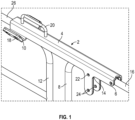
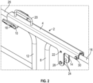
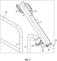
- FIG. 1-3 show a perspective view of a latching gate fastener according to the invention that is mounted on a double gate in the closed position ( Figures 1 and 2 ) and in the open position ( Figure 3 ).
- a gate fastener (2) mounted on a double gate (8, 12).
- a pivot pin (30) is secured through two aligned apertures (6) in the gate fastener (2) and a corresponding set of aligned apertures (not shown) in the top rail (16) of the first gate (8).
- This provides the gate fastener (2) with a pivotable body (4) that pivots about an axis (6).
- the pivot pin (30) passing through the apertures (6) in the fastener and rail both secures the fastener to the rail and enables it to pivot about axis (6).
- An inverted U-shaped recess (14) runs the length of the body and fits over the top rails (16, 26) of both gates (8, 12).
- a further pin or bolt (28) is secured through two aligned apertures (24) in a downwardly projecting portion or lug of the pivotable body (4).
- This provides the gate fastener (2) with a pivot stop, such that when the pivotable body (4) is pivoted about axis (6) upwards and away from the gate rail (26) of the second gate (12), i.e., by pulling on the handle (20), pivoting is restricted by the pivot stop pin or bolt (28) abutting the underside of the gate rail (16) of the first gate (8).
- the gates (8, 12) can swing towards one another in either direction, since there are two separate ramps (10) on opposing surfaces of the gate fastener (2).
- the pivotable body (4) then falls downward under its own weight and secures the top rail (26) of the second gate (12) within its recess (14), such that the gates (8, 12) are held in the closed position.
- the gate fastener (2) is then optionally locked in the closed position using a pin (not shown) that passes through aligned apertures (22) in the downwardly projecting portions or lugs of the pivotable body (4), i.e., with the fastener in the closed position and the pin in place, when the user pulls on the handle (20) pivoting into a sufficiently raised position in which the gates can be opened is prevented by the locking pin abutting the underside of the gate rail (16) of the first gate (8).
- the gate fastener (2) may also optionally be locked in the open position using a pin (not shown) that passes through aligned apertures (22) in the downwardly projecting portion of the pivotable body (4). This is achieved by inserting the pin through the apertures (22) when the gate fastener (2) is in the raised, open position and the apertures (22) sit above the top rail (16) of the first gate (8), i.e., when pushing down on the handle (20), pivoting is prevented by the locking pin abutting the topside of the gate rail (16) of the first gate (8).
- the invention hence provides a latching gate fastener for double gates.
Landscapes
- Engineering & Computer Science (AREA)
- Structural Engineering (AREA)
- Mechanical Engineering (AREA)
- Civil Engineering (AREA)
- Gates (AREA)
Abstract
Description
- The present invention relates to gate latches, specifically for use with double gates, and to gates having such latches affixed.
- Various types of gate latches are known in the technical field, however the common function amongst all types is that the gates to which latches are affixed can be secured in the closed position.
- A variety of latching means for use in conjunction with a swing gate, and its adjacent gatepost, are known in the art. Normally, these latching means incorporate rather complex structures arranged internal to the gatepost to which the gate latch affixes.
- Less common are fastening means for use in conjunction with a swing gate that lies adjacent to another swing gate (AKA a double gate).
- One known fastener that works to secure one swing gate of a double gate to the other swing gate works by being pivotally mounted to the top of one of the gates. When in the open position, the gates can swing freely (often in only one direction, due to the presence of a hinge stop). In order to close the gates and prevent the swinging thereof, the fastener is pivoted 180 degrees from a first position in which it lies across and is supported by the gate to which it is affixed to a second position in which it mounts the other gate as well. These types of gate fasteners are typically referred to as "throw over gate loops".
- A significant problem with known double gate fasteners of this kind, however, is that a user must remember to close the gates after each use. Otherwise, the gates will either swing freely (when the fastener lies across and is supported by the gate to which it is affixed) or one will crash into the extended fastener of another (if the fastener has been left in the "closed" position, but not over and hence without securing each of the two gates). The first instance is likely to result in damage to the gates and the gate hinges, as well as being a security risk. The second instance is additionally likely to lead to damage of the fastener itself.
- It is thus clear from the technical field that there exists a need for an alternative and, preferably, improved gate fastener that provides the end user with both convenience and security for minimal cost.
- An aim of the present invention is therefore to provide a new and improved latching gate fastener for a double gate.
- Accordingly, the invention provides a latching gate fastener suitable for securing a double gate, comprising:
- a pivotable body that is suitably fixable (e.g., using a screw, pin or bolt) to a first gate; and
- at least one ramp that is suitable for contacting a second gate,
- wherein the pivotable body comprises at least one recess for receiving a gate rail on the second gate.
- Preferably, the pivot point of the pivotable body is at a proximal end of the latching gate fastener. Preferably, the at least one ramp (or strike plate) is at a distal end of the latching gate fastener.
- The pivotable body comprising a recess for receiving a gate rail may otherwise be known as a throw over gate loop.
- Hence, the invention provides a gate fastener, comprising
- a proximal pivot point, for pivotal attachment to a gate, and
- a distal throw over gate loop,
- further comprising a distal strike plate for latching upon horizontal engagement with a second gate.
- The ramp / strike plate is a sloped surface or projection that advantageously facilitates sideways latching of the second gate into the fastened position. Contrary to known throw over gate loops in the art, the gate fastener of the present invention allows for the pivotable body to be left in the "closed" position, without the second gate being secured within the recess, while allowing sideways movement of the second gate to result in movement of the fastener into the secured position without a user manually lifting the pivotable body. As shown in the example below, the angle and arrangement of the strike plate / ramp with respect to the second gate rail is such that when the second gate rail engages it laterally this results in upwards movement of the fastener body, meaning the end of the fastener adjacent the second rail is raised, then the second rail passes into the recess and the fastener drops into a closed position, securing the second rail and holding the double gates together. This not only protects the gate fastener from damage from lateral impacts as the gate slams into the side of the gate fastener, it also allows for the gates to be closed automatically in the case they are unintentionally left open. Closing can be achieved by pushing the gates together, e.g., by a user or otherwise, e.g., by the action of the wind.
- In a preferred embodiment the ramp / strike plate is at an angle 30-60 degrees from horizontal. Preferably, the ramp is angled 50 degrees from horizontal.
- When referring to the "open" and "closed" positions of the gate fastener / pivotable body, the open position refers to situations wherein the pivotable body is pivoted upward such that the second gate can freely pass under the gate fastener, while the closed position refers to situations wherein the pivotable body is pivoted downward such that the second gate either sits within its recess or contacts the at least one ramp. This contrasts from the definition of the gate itself being "open" or "closed", in that the gate is open when a user can freely pass through it, i.e., the gate does not sit within the recess of the pivotable body, however the gate may be open at times when the gate fastener is in the closed position.
- As such, it is preferred that the latching gate fastener comprises at least two ramps, one each on opposing surfaces of the pivotable body. This allows for the gates to swing towards one another in either direction, whilst facilitating the latching of the gate fastener as the pivotable body is moved upwards and over the second gate rail, allowing the second gate rail to fit into the recess in the pivotable body and thus be secured in the closed position.
- The ramp surface is suitably flat and smooth. Generally, the fastener is made of metal (although other materials, e.g., plastic, may be suitable). The one or more ramps / strike plates may be composed of or have fitted thereto an outer lining, typically non-metallic. The lining may absorb impacts with the second rail. The lining may be of material that assists the smooth and controlled movement of the second gate rail into the recess. In the example below, a rubber pad is mounted to the ramp for this purpose. Although a pad is not essential to the invention, it assists in providing a smooth and controlled latching action, as well as protecting the gate finish. The pad is suitably composed of a hard rubber or high-density polyethylene (HDPE). A brass plate may optionally be fitted in place of the pad.
- Typically, a handle is provided to assist lifting the pivotable body away from the second gate and into the "open" position. Preferably, the handle is provided at the distal end of the gate fastener.
- It is preferred that the latching gate fastener further comprises a locking means to prevent pivoting of the pivotable body. This provides the benefit that, when desirable, the gate fastener can be locked in position to more permanently secure the two gates together, i.e., by preventing a user from lifting the pivotable body away from the second gate rail. Optionally, however, the locking means may be used to secure the gate fastener more permanently in the open position (i.e., where it does not contact the second gate when the two gates are brought in alignment with each other).
- Hence, the invention provides a gate fastener, comprising
- a proximal pivot point, for pivotal attachment to a gate, and
- a distal throw over gate loop,
- further comprising one or more lugs, apertures and/or ears for attachment of a retainer that when in place restricts pivoting of the throw over gate loop and locks the fastener to a second gate.
- It is preferred that the locking means comprises at least one aperture in the pivotable body and a fastener passing through said aperture to lock the pivotable body in position. Preferably, the fastener is a pin for easy insertion / removal. Preferably, there are two apertures located on either side of the recess and aligned with one another under the gate rail, so that when the fastener is passed through the apertures, it blocks upward movement of the pivotable body. Preferably, the two apertures are positioned proximally of the gate fastener.
- It is preferred that the latching gate fastener further comprises a pivot stop that in use allows partial pivoting of the pivotable body but prevents full pivotable movement of the pivotable body. Advantageously, the presence of the pivot stop means that the pivotable body cannot be pivoted into a position in which it cannot freely fall back into the closed position (unless the locking means are utilized to secure the fastening means in the open position more permanently). This is beneficial because it protects against user error, i.e., where the user has opened the gate and accidentally forgotten to close the gate after use.
- Hence, the invention provides a gate fastener, comprising
- a proximal pivot point, for pivotal attachment to a gate, and
- a distal throw over gate loop,
- further comprising one or more lugs, apertures and/or ears for attachment of a retainer that when in place restricts pivoting of the throw over gate loop between a first position in which it secures the fastener to a second gate and a second position in which the fastener is unlocked and from which when released the gate loop falls back into the first position.
- It is preferred that the pivot stop comprises at least one aperture in the pivotable body and a fastener passing through said aperture to limit pivot range of the pivotable body. Preferably, the fastener is a pin, screw or bolt. Preferably, there are two apertures located on either side of the recess and aligned with one another under the gate rail, so that when the fastener is passed through the apertures, it limits upward movement of the pivotable body. Preferably, the two apertures are positioned distally of the gate fastener.
- Preferably, the pivotable body is metal in composition. Typically, it is formed from a single extrusion.
- The invention also provides a method for securing a double gate from opening, comprising
- fixing a latching gate fastener having a pivotable body to a first gate, such that the pivotable body may be pivoted about a first gate rail of the first gate;
- wherein in the closed position the pivotable body lies aligned with the first gate rail and at least partially houses it within a recess in the pivotable body; and
- wherein in the closed position the pivotable body lies aligned with a second gate rail on a second gate and at least partially houses it within a recess in the pivotable body;
- characterised in that the pivotable body comprises at least one ramp / strike plate for contacting the second gate rail, such that when the two gates are out of alignment the second gate swings toward the first gate, allowing the second gate rail to contact the ramp and lift the pivotable body enough that the second gate rail passes under the ramp and into the recess of the pivotable body, where it is secured in the closed position.
- The latching gate fastener for use in the method of the invention is preferably as described elsewhere herein and illustrated in the example in more detail.
- In another embodiment, the invention provides a gate comprising the latching gate fastener of the invention.
- The invention is now illustrated in specific examples, with reference to the accompanying drawings (
Figures 1-3 ) which show a perspective view of a latching gate fastener according to the invention that is mounted on a double gate in the closed position (Figures 1 and2 ) and in the open position (Figure 3 ). - There is shown a gate fastener (2) according to the invention mounted on a double gate (8, 12). A pivot pin (30) is secured through two aligned apertures (6) in the gate fastener (2) and a corresponding set of aligned apertures (not shown) in the top rail (16) of the first gate (8). This provides the gate fastener (2) with a pivotable body (4) that pivots about an axis (6). The pivot pin (30) passing through the apertures (6) in the fastener and rail both secures the fastener to the rail and enables it to pivot about axis (6). An inverted U-shaped recess (14) runs the length of the body and fits over the top rails (16, 26) of both gates (8, 12).
- A further pin or bolt (28) is secured through two aligned apertures (24) in a downwardly projecting portion or lug of the pivotable body (4). This provides the gate fastener (2) with a pivot stop, such that when the pivotable body (4) is pivoted about axis (6) upwards and away from the gate rail (26) of the second gate (12), i.e., by pulling on the handle (20), pivoting is restricted by the pivot stop pin or bolt (28) abutting the underside of the gate rail (16) of the first gate (8).
- With that pin or bolt (28) in place, sufficient pivoting movement of the body is permitted for the recess to clear the second gate rail to open the gate. Upon lifting of the handle (20) and hence opening of the gate fastener (2), which clears the top rail (26) of the second gate, the user can open and pass through the double gates (8, 12). The user can then close and realign the gates and allow the gate fastener (2) to drop back into its closed position.
- If the gates (8, 12) remain open, despite the gate fastener (2) being in the closed position, there is provided a set of two ramps or strike plates (10) to assist in the closing / latching of the gates (8, 12). The ramps are fitted with rubber pads (18) to assist the smooth and controlled latching of the gates (8, 12) into their closed positions.
- The gates (8, 12) can swing towards one another in either direction, since there are two separate ramps (10) on opposing surfaces of the gate fastener (2). As the top rail (26) of the second gate (12) swings towards and then contacts the ramp (10), sideways engagement of the top rail against the angled ramp pushes the body upwards and the pivotable body (4) of the gate fastener (2) is lifted, allowing the top rail (26) of the second gate (12) to be positioned under the U-shaped recess (14) which runs the length of the pivotable body (4). The pivotable body (4) then falls downward under its own weight and secures the top rail (26) of the second gate (12) within its recess (14), such that the gates (8, 12) are held in the closed position.
- The gate fastener (2) is then optionally locked in the closed position using a pin (not shown) that passes through aligned apertures (22) in the downwardly projecting portions or lugs of the pivotable body (4), i.e., with the fastener in the closed position and the pin in place, when the user pulls on the handle (20) pivoting into a sufficiently raised position in which the gates can be opened is prevented by the locking pin abutting the underside of the gate rail (16) of the first gate (8).
- The gate fastener (2) may also optionally be locked in the open position using a pin (not shown) that passes through aligned apertures (22) in the downwardly projecting portion of the pivotable body (4). This is achieved by inserting the pin through the apertures (22) when the gate fastener (2) is in the raised, open position and the apertures (22) sit above the top rail (16) of the first gate (8), i.e., when pushing down on the handle (20), pivoting is prevented by the locking pin abutting the topside of the gate rail (16) of the first gate (8).
-
- Latching gate fastener (2)
- Pivotable body (4)
- Pivot aperture / axis (6)
- First gate (8)
- Ramp / strike plate (10)
- Second gate (12)
- Recess (14)
- First gate rail (16)
- Rubber pad (18)
- Handle (20)
- Locking pin aperture (22)
- Pivot stop apertures (24)
- Second gate rail (26)
- Pivot stop (28)
- Pivot pin (30)
- The invention hence provides a latching gate fastener for double gates.
Claims (15)
- A latching gate fastener (2) for securing a double gate (8, 12), comprising:a pivotable body (4) that is fixable (e.g., using a screw) to a first gate (8); andat least one ramp or strike plate (10) for contacting a second gate (12),wherein the pivotable body comprises at least one recess (14) for receiving a gate rail (26) on the second gate.
- A latching gate fastener according to claim 1, wherein there are at least two ramps present on opposing surfaces of the pivotable body.
- A latching gate fastener according to claim 1 or 2, wherein the at least one ramp or at least two ramps comprise a rubber surface (18) for contacting the second gate.
- A latching gate fastener according to any preceding claim, further comprising a handle (20) for lifting the pivotable body away from the second gate.
- A latching gate fastener according to any preceding claim, further comprising a locking means to prevent pivoting of the pivotable body in use.
- A latching gate fastener according to claim 5, wherein the locking means comprises at least one aperture (22) in the pivotable body and a fastener passing through said aperture (e.g., a pin).
- A latching gate fastener according to any preceding claim, further comprising a pivot stop that in use allows partial pivoting of the pivotable body but prevents full pivotable movement of the pivotable body.
- A latching gate fastener according to claim 7, wherein the pivot stop comprises at least one aperture (24) in the pivotable body and a fastener passing through said aperture (e.g., a screw).
- A latching gate fastener according to any preceding claim, wherein the pivotable body is metal in composition and, preferably, formed from a single extrusion.
- A method for securing a double gate (8, 12) from opening, comprisingfixing a latching gate fastener (2) having a pivotable body (4) to a first gate (8), such that the pivotable body may be pivoted about a first gate rail (16) of the first gate;wherein in the closed position the pivotable body lies in line with the first gate rail and at least partially houses it within a recess (14) in the pivotable body;wherein in the closed position the pivotable body lies in line with a second gate rail (26) on a second gate (12) and at least partially houses it within a recess in the pivotable body; andcharacterised in that the pivotable body comprises at least one ramp or strike plate (10) for contacting the second gate rail, such that when the two gates are out of alignment the second gate swings toward the first gate, allowing the second gate rail to contact the ramp and lift the pivotable body enough that the second gate rail passes under the ramp and into the recess of the pivotable body, where it is secured in the closed position.
- A method according to claim 10, wherein the pivotable body comprises two ramps on opposing surfaces of the pivotable body, the first ramp for contacting the second gate rail on a first side thereof, and the second ramp for contacting the second gate rail on a second side thereof
- A method according to claim 10 or 11, wherein the pivotable body comprises a locking means, for example two apertures (22) in alignment and positioned below one of the first or second rails, such that a fastener (e.g., a pin) can be passed through each of the apertures, so as to prevent pivotable movement of the pivotable body and hence lock the two gates together.
- A method according to any of claims 10 to 12, wherein the pivotable body comprises a pivot stop, so as to allow partial pivoting of the pivotable body but prevent full pivotable movement of the pivotable body.
- A method according to claim 12 or 13, wherein the locking means and pivot stop both comprise two apertures, with corresponding fasteners, in alignment and positioned below the first gate rail.
- A gate (8) comprising a latching gate fastener (2) according to any of claims 1 to 9.
Priority Applications (2)
| Application Number | Priority Date | Filing Date | Title |
|---|---|---|---|
| EP22201006.8A EP4353929B1 (en) | 2022-10-12 | 2022-10-12 | Double gate fastener |
| DK22201006.8T DK4353929T3 (en) | 2022-10-12 | 2022-10-12 | DOUBLE DOOR ATTACHMENT |
Applications Claiming Priority (1)
| Application Number | Priority Date | Filing Date | Title |
|---|---|---|---|
| EP22201006.8A EP4353929B1 (en) | 2022-10-12 | 2022-10-12 | Double gate fastener |
Publications (2)
| Publication Number | Publication Date |
|---|---|
| EP4353929A1 true EP4353929A1 (en) | 2024-04-17 |
| EP4353929B1 EP4353929B1 (en) | 2025-04-23 |
Family
ID=83691111
Family Applications (1)
| Application Number | Title | Priority Date | Filing Date |
|---|---|---|---|
| EP22201006.8A Active EP4353929B1 (en) | 2022-10-12 | 2022-10-12 | Double gate fastener |
Country Status (2)
| Country | Link |
|---|---|
| EP (1) | EP4353929B1 (en) |
| DK (1) | DK4353929T3 (en) |
Citations (2)
| Publication number | Priority date | Publication date | Assignee | Title |
|---|---|---|---|---|
| FR2519060A1 (en) * | 1981-12-24 | 1983-07-01 | Mignot Cie | Lock for double gates - comprises arm pivotally attached to one gate which secures to gate opposite |
| DE202020000327U1 (en) * | 2020-01-28 | 2020-02-18 | Volker Nagel | Throw bar for 2-leaf gates |
-
2022
- 2022-10-12 EP EP22201006.8A patent/EP4353929B1/en active Active
- 2022-10-12 DK DK22201006.8T patent/DK4353929T3/en active
Patent Citations (2)
| Publication number | Priority date | Publication date | Assignee | Title |
|---|---|---|---|---|
| FR2519060A1 (en) * | 1981-12-24 | 1983-07-01 | Mignot Cie | Lock for double gates - comprises arm pivotally attached to one gate which secures to gate opposite |
| DE202020000327U1 (en) * | 2020-01-28 | 2020-02-18 | Volker Nagel | Throw bar for 2-leaf gates |
Also Published As
| Publication number | Publication date |
|---|---|
| DK4353929T3 (en) | 2025-05-19 |
| EP4353929B1 (en) | 2025-04-23 |
Similar Documents
| Publication | Publication Date | Title |
|---|---|---|
| US6308462B1 (en) | Child safety barrier | |
| US7017954B2 (en) | Door latch assembly | |
| US4904007A (en) | Releasing latch assembly for picnic coolers | |
| EP0644308A1 (en) | Lock for sliding door | |
| US6253417B1 (en) | Door holder and stop with retaining means for holding a door shut while in a closed position | |
| US20230349206A1 (en) | Gate latch | |
| US20130020813A1 (en) | Door latch assembly with movable lock plate | |
| US12559983B2 (en) | Box construction lock | |
| CA2167035C (en) | Self-tightening side lock for a roll-up door | |
| US7883124B2 (en) | Gate latch | |
| US20170016248A1 (en) | Tool operated channel latch | |
| US20110221211A1 (en) | Self-Locking Latch for Window Sash | |
| US7322153B2 (en) | Baby gate | |
| EP4353929B1 (en) | Double gate fastener | |
| US5013073A (en) | Automatic reset window latch | |
| US10871012B2 (en) | End door latch arrangement for railroad car | |
| GB2088463A (en) | A child safety device for a closure securing member | |
| GB2509632A (en) | A blocking device for use with a friction hinge | |
| US5360246A (en) | Latch plate for storage lockers | |
| US20240360712A1 (en) | Hinge locking mechanism | |
| US20110163553A1 (en) | Multipoint lock extension for a round top door | |
| US20240263497A1 (en) | Integrated locking pin | |
| US4124184A (en) | Door catch | |
| US3998484A (en) | Sliding door locking device | |
| JPS625092Y2 (en) |
Legal Events
| Date | Code | Title | Description |
|---|---|---|---|
| PUAI | Public reference made under article 153(3) epc to a published international application that has entered the european phase |
Free format text: ORIGINAL CODE: 0009012 |
|
| STAA | Information on the status of an ep patent application or granted ep patent |
Free format text: STATUS: THE APPLICATION HAS BEEN PUBLISHED |
|
| AK | Designated contracting states |
Kind code of ref document: A1 Designated state(s): AL AT BE BG CH CY CZ DE DK EE ES FI FR GB GR HR HU IE IS IT LI LT LU LV MC ME MK MT NL NO PL PT RO RS SE SI SK SM TR |
|
| STAA | Information on the status of an ep patent application or granted ep patent |
Free format text: STATUS: REQUEST FOR EXAMINATION WAS MADE |
|
| REG | Reference to a national code |
Ref country code: DE Free format text: PREVIOUS MAIN CLASS: E05B0065000000 Ref legal event code: R079 Ref document number: 602022013474 Country of ref document: DE Ipc: E05B0063180000 |
|
| 17P | Request for examination filed |
Effective date: 20241004 |
|
| RBV | Designated contracting states (corrected) |
Designated state(s): AL AT BE BG CH CY CZ DE DK EE ES FI FR GB GR HR HU IE IS IT LI LT LU LV MC ME MK MT NL NO PL PT RO RS SE SI SK SM TR |
|
| GRAP | Despatch of communication of intention to grant a patent |
Free format text: ORIGINAL CODE: EPIDOSNIGR1 |
|
| STAA | Information on the status of an ep patent application or granted ep patent |
Free format text: STATUS: GRANT OF PATENT IS INTENDED |
|
| RIN1 | Information on inventor provided before grant (corrected) |
Inventor name: NAPTHINE, SIMON GARTH |
|
| RIC1 | Information provided on ipc code assigned before grant |
Ipc: E05C 7/04 20060101ALI20241104BHEP Ipc: E05B 65/00 20060101ALI20241104BHEP Ipc: E06B 11/02 20060101ALI20241104BHEP Ipc: E05B 15/16 20060101ALI20241104BHEP Ipc: E05C 3/14 20060101ALI20241104BHEP Ipc: E05B 63/18 20060101AFI20241104BHEP |
|
| INTG | Intention to grant announced |
Effective date: 20241121 |
|
| GRAS | Grant fee paid |
Free format text: ORIGINAL CODE: EPIDOSNIGR3 |
|
| GRAA | (expected) grant |
Free format text: ORIGINAL CODE: 0009210 |
|
| STAA | Information on the status of an ep patent application or granted ep patent |
Free format text: STATUS: THE PATENT HAS BEEN GRANTED |
|
| P01 | Opt-out of the competence of the unified patent court (upc) registered |
Free format text: CASE NUMBER: APP_9116/2025 Effective date: 20250224 |
|
| AK | Designated contracting states |
Kind code of ref document: B1 Designated state(s): AL AT BE BG CH CY CZ DE DK EE ES FI FR GB GR HR HU IE IS IT LI LT LU LV MC ME MK MT NL NO PL PT RO RS SE SI SK SM TR |
|
| REG | Reference to a national code |
Ref country code: GB Ref legal event code: FG4D |
|
| REG | Reference to a national code |
Ref country code: CH Ref legal event code: EP |
|
| REG | Reference to a national code |
Ref country code: DE Ref legal event code: R096 Ref document number: 602022013474 Country of ref document: DE |
|
| REG | Reference to a national code |
Ref country code: DK Ref legal event code: T3 Effective date: 20250515 |
|
| REG | Reference to a national code |
Ref country code: IE Ref legal event code: FG4D |
|
| REG | Reference to a national code |
Ref country code: NL Ref legal event code: MP Effective date: 20250423 |
|
| PG25 | Lapsed in a contracting state [announced via postgrant information from national office to epo] |
Ref country code: NL Free format text: LAPSE BECAUSE OF FAILURE TO SUBMIT A TRANSLATION OF THE DESCRIPTION OR TO PAY THE FEE WITHIN THE PRESCRIBED TIME-LIMIT Effective date: 20250423 |
|
| REG | Reference to a national code |
Ref country code: AT Ref legal event code: MK05 Ref document number: 1787900 Country of ref document: AT Kind code of ref document: T Effective date: 20250423 |
|
| PG25 | Lapsed in a contracting state [announced via postgrant information from national office to epo] |
Ref country code: FI Free format text: LAPSE BECAUSE OF FAILURE TO SUBMIT A TRANSLATION OF THE DESCRIPTION OR TO PAY THE FEE WITHIN THE PRESCRIBED TIME-LIMIT Effective date: 20250423 Ref country code: PT Free format text: LAPSE BECAUSE OF FAILURE TO SUBMIT A TRANSLATION OF THE DESCRIPTION OR TO PAY THE FEE WITHIN THE PRESCRIBED TIME-LIMIT Effective date: 20250825 Ref country code: ES Free format text: LAPSE BECAUSE OF FAILURE TO SUBMIT A TRANSLATION OF THE DESCRIPTION OR TO PAY THE FEE WITHIN THE PRESCRIBED TIME-LIMIT Effective date: 20250423 |
|
| REG | Reference to a national code |
Ref country code: LT Ref legal event code: MG9D |
|
| PG25 | Lapsed in a contracting state [announced via postgrant information from national office to epo] |
Ref country code: NO Free format text: LAPSE BECAUSE OF FAILURE TO SUBMIT A TRANSLATION OF THE DESCRIPTION OR TO PAY THE FEE WITHIN THE PRESCRIBED TIME-LIMIT Effective date: 20250723 Ref country code: GR Free format text: LAPSE BECAUSE OF FAILURE TO SUBMIT A TRANSLATION OF THE DESCRIPTION OR TO PAY THE FEE WITHIN THE PRESCRIBED TIME-LIMIT Effective date: 20250724 |
|
| PG25 | Lapsed in a contracting state [announced via postgrant information from national office to epo] |
Ref country code: PL Free format text: LAPSE BECAUSE OF FAILURE TO SUBMIT A TRANSLATION OF THE DESCRIPTION OR TO PAY THE FEE WITHIN THE PRESCRIBED TIME-LIMIT Effective date: 20250423 |
|
| PG25 | Lapsed in a contracting state [announced via postgrant information from national office to epo] |
Ref country code: BG Free format text: LAPSE BECAUSE OF FAILURE TO SUBMIT A TRANSLATION OF THE DESCRIPTION OR TO PAY THE FEE WITHIN THE PRESCRIBED TIME-LIMIT Effective date: 20250423 |
|
| PG25 | Lapsed in a contracting state [announced via postgrant information from national office to epo] |
Ref country code: HR Free format text: LAPSE BECAUSE OF FAILURE TO SUBMIT A TRANSLATION OF THE DESCRIPTION OR TO PAY THE FEE WITHIN THE PRESCRIBED TIME-LIMIT Effective date: 20250423 |
|
| PG25 | Lapsed in a contracting state [announced via postgrant information from national office to epo] |
Ref country code: AT Free format text: LAPSE BECAUSE OF FAILURE TO SUBMIT A TRANSLATION OF THE DESCRIPTION OR TO PAY THE FEE WITHIN THE PRESCRIBED TIME-LIMIT Effective date: 20250423 |
|
| PG25 | Lapsed in a contracting state [announced via postgrant information from national office to epo] |
Ref country code: RS Free format text: LAPSE BECAUSE OF FAILURE TO SUBMIT A TRANSLATION OF THE DESCRIPTION OR TO PAY THE FEE WITHIN THE PRESCRIBED TIME-LIMIT Effective date: 20250723 |
|
| PG25 | Lapsed in a contracting state [announced via postgrant information from national office to epo] |
Ref country code: IS Free format text: LAPSE BECAUSE OF FAILURE TO SUBMIT A TRANSLATION OF THE DESCRIPTION OR TO PAY THE FEE WITHIN THE PRESCRIBED TIME-LIMIT Effective date: 20250823 |
|
| PG25 | Lapsed in a contracting state [announced via postgrant information from national office to epo] |
Ref country code: LV Free format text: LAPSE BECAUSE OF FAILURE TO SUBMIT A TRANSLATION OF THE DESCRIPTION OR TO PAY THE FEE WITHIN THE PRESCRIBED TIME-LIMIT Effective date: 20250423 |
|
| PGFP | Annual fee paid to national office [announced via postgrant information from national office to epo] |
Ref country code: DE Payment date: 20251024 Year of fee payment: 4 |
|
| PG25 | Lapsed in a contracting state [announced via postgrant information from national office to epo] |
Ref country code: SM Free format text: LAPSE BECAUSE OF FAILURE TO SUBMIT A TRANSLATION OF THE DESCRIPTION OR TO PAY THE FEE WITHIN THE PRESCRIBED TIME-LIMIT Effective date: 20250423 |
|
| PGFP | Annual fee paid to national office [announced via postgrant information from national office to epo] |
Ref country code: DK Payment date: 20251016 Year of fee payment: 4 |
|
| PGFP | Annual fee paid to national office [announced via postgrant information from national office to epo] |
Ref country code: FR Payment date: 20251017 Year of fee payment: 4 |
|
| PG25 | Lapsed in a contracting state [announced via postgrant information from national office to epo] |
Ref country code: CZ Free format text: LAPSE BECAUSE OF FAILURE TO SUBMIT A TRANSLATION OF THE DESCRIPTION OR TO PAY THE FEE WITHIN THE PRESCRIBED TIME-LIMIT Effective date: 20250423 |
|
| PG25 | Lapsed in a contracting state [announced via postgrant information from national office to epo] |
Ref country code: EE Free format text: LAPSE BECAUSE OF FAILURE TO SUBMIT A TRANSLATION OF THE DESCRIPTION OR TO PAY THE FEE WITHIN THE PRESCRIBED TIME-LIMIT Effective date: 20250423 |
|
| REG | Reference to a national code |
Ref country code: DE Ref legal event code: R097 Ref document number: 602022013474 Country of ref document: DE |
|
| PG25 | Lapsed in a contracting state [announced via postgrant information from national office to epo] |
Ref country code: SK Free format text: LAPSE BECAUSE OF FAILURE TO SUBMIT A TRANSLATION OF THE DESCRIPTION OR TO PAY THE FEE WITHIN THE PRESCRIBED TIME-LIMIT Effective date: 20250423 |
|
| PG25 | Lapsed in a contracting state [announced via postgrant information from national office to epo] |
Ref country code: IT Free format text: LAPSE BECAUSE OF FAILURE TO SUBMIT A TRANSLATION OF THE DESCRIPTION OR TO PAY THE FEE WITHIN THE PRESCRIBED TIME-LIMIT Effective date: 20250423 |
|
| PLBE | No opposition filed within time limit |
Free format text: ORIGINAL CODE: 0009261 |
|
| STAA | Information on the status of an ep patent application or granted ep patent |
Free format text: STATUS: NO OPPOSITION FILED WITHIN TIME LIMIT |
|
| REG | Reference to a national code |
Ref country code: CH Ref legal event code: L10 Free format text: ST27 STATUS EVENT CODE: U-0-0-L10-L00 (AS PROVIDED BY THE NATIONAL OFFICE) Effective date: 20260304 |
|
| PG25 | Lapsed in a contracting state [announced via postgrant information from national office to epo] |
Ref country code: RO Free format text: LAPSE BECAUSE OF FAILURE TO SUBMIT A TRANSLATION OF THE DESCRIPTION OR TO PAY THE FEE WITHIN THE PRESCRIBED TIME-LIMIT Effective date: 20250423 |
|
| 26N | No opposition filed |
Effective date: 20260126 |
|
| REG | Reference to a national code |
Ref country code: CH Ref legal event code: H13 Free format text: ST27 STATUS EVENT CODE: U-0-0-H10-H13 (AS PROVIDED BY THE NATIONAL OFFICE) Effective date: 20260527 |
|
| PG25 | Lapsed in a contracting state [announced via postgrant information from national office to epo] |
Ref country code: LU Free format text: LAPSE BECAUSE OF NON-PAYMENT OF DUE FEES Effective date: 20251012 |
|
| REG | Reference to a national code |
Ref country code: BE Ref legal event code: MM Effective date: 20251031 |
|
| PG25 | Lapsed in a contracting state [announced via postgrant information from national office to epo] |
Ref country code: LT Free format text: LAPSE BECAUSE OF FAILURE TO SUBMIT A TRANSLATION OF THE DESCRIPTION OR TO PAY THE FEE WITHIN THE PRESCRIBED TIME-LIMIT Effective date: 20250423 |
|
| PG25 | Lapsed in a contracting state [announced via postgrant information from national office to epo] |
Ref country code: MC Free format text: LAPSE BECAUSE OF FAILURE TO SUBMIT A TRANSLATION OF THE DESCRIPTION OR TO PAY THE FEE WITHIN THE PRESCRIBED TIME-LIMIT Effective date: 20250423 |
|
| PG25 | Lapsed in a contracting state [announced via postgrant information from national office to epo] |
Ref country code: BE Free format text: LAPSE BECAUSE OF NON-PAYMENT OF DUE FEES Effective date: 20251031 Ref country code: CH Free format text: LAPSE BECAUSE OF NON-PAYMENT OF DUE FEES Effective date: 20251031 |
|
| PG25 | Lapsed in a contracting state [announced via postgrant information from national office to epo] |
Ref country code: SE Free format text: LAPSE BECAUSE OF FAILURE TO SUBMIT A TRANSLATION OF THE DESCRIPTION OR TO PAY THE FEE WITHIN THE PRESCRIBED TIME-LIMIT Effective date: 20250423 |