EP4353811A2 - Enzyme reactor - Google Patents
Enzyme reactor Download PDFInfo
- Publication number
- EP4353811A2 EP4353811A2 EP23202087.5A EP23202087A EP4353811A2 EP 4353811 A2 EP4353811 A2 EP 4353811A2 EP 23202087 A EP23202087 A EP 23202087A EP 4353811 A2 EP4353811 A2 EP 4353811A2
- Authority
- EP
- European Patent Office
- Prior art keywords
- enzyme
- reaction
- electrolytic solution
- cathodic
- chamber
- Prior art date
- Legal status (The legal status is an assumption and is not a legal conclusion. Google has not performed a legal analysis and makes no representation as to the accuracy of the status listed.)
- Pending
Links
- 102000004190 Enzymes Human genes 0.000 title claims abstract description 276
- 108090000790 Enzymes Proteins 0.000 title claims abstract description 276
- 238000006911 enzymatic reaction Methods 0.000 claims abstract description 281
- 239000008151 electrolyte solution Substances 0.000 claims abstract description 224
- 239000012528 membrane Substances 0.000 claims abstract description 189
- 239000000243 solution Substances 0.000 claims abstract description 138
- 239000011941 photocatalyst Substances 0.000 claims abstract description 94
- 238000006243 chemical reaction Methods 0.000 claims abstract description 79
- 239000000758 substrate Substances 0.000 claims abstract description 63
- 239000012466 permeate Substances 0.000 claims abstract description 59
- 238000013032 photocatalytic reaction Methods 0.000 claims abstract description 59
- 239000002994 raw material Substances 0.000 claims abstract description 46
- 238000005192 partition Methods 0.000 claims abstract description 22
- 239000003014 ion exchange membrane Substances 0.000 claims abstract description 18
- CURLTUGMZLYLDI-UHFFFAOYSA-N Carbon dioxide Chemical compound O=C=O CURLTUGMZLYLDI-UHFFFAOYSA-N 0.000 claims description 115
- 239000001569 carbon dioxide Substances 0.000 claims description 63
- 229910002092 carbon dioxide Inorganic materials 0.000 claims description 63
- 239000000126 substance Substances 0.000 abstract description 125
- 238000006722 reduction reaction Methods 0.000 abstract description 101
- 238000000034 method Methods 0.000 abstract description 43
- 230000008569 process Effects 0.000 abstract description 28
- 238000000502 dialysis Methods 0.000 description 53
- XJLXINKUBYWONI-DQQFMEOOSA-N [[(2r,3r,4r,5r)-5-(6-aminopurin-9-yl)-3-hydroxy-4-phosphonooxyoxolan-2-yl]methoxy-hydroxyphosphoryl] [(2s,3r,4s,5s)-5-(3-carbamoylpyridin-1-ium-1-yl)-3,4-dihydroxyoxolan-2-yl]methyl phosphate Chemical compound NC(=O)C1=CC=C[N+]([C@@H]2[C@H]([C@@H](O)[C@H](COP([O-])(=O)OP(O)(=O)OC[C@@H]3[C@H]([C@@H](OP(O)(O)=O)[C@@H](O3)N3C4=NC=NC(N)=C4N=C3)O)O2)O)=C1 XJLXINKUBYWONI-DQQFMEOOSA-N 0.000 description 41
- BDAGIHXWWSANSR-UHFFFAOYSA-N methanoic acid Natural products OC=O BDAGIHXWWSANSR-UHFFFAOYSA-N 0.000 description 34
- 238000005842 biochemical reaction Methods 0.000 description 32
- 230000009467 reduction Effects 0.000 description 28
- 238000007254 oxidation reaction Methods 0.000 description 27
- 235000019253 formic acid Nutrition 0.000 description 23
- 230000001678 irradiating effect Effects 0.000 description 21
- 238000004519 manufacturing process Methods 0.000 description 21
- 230000003647 oxidation Effects 0.000 description 21
- RGJOEKWQDUBAIZ-IBOSZNHHSA-N CoASH Chemical compound O[C@@H]1[C@H](OP(O)(O)=O)[C@@H](COP(O)(=O)OP(O)(=O)OCC(C)(C)[C@@H](O)C(=O)NCCC(=O)NCCS)O[C@H]1N1C2=NC=NC(N)=C2N=C1 RGJOEKWQDUBAIZ-IBOSZNHHSA-N 0.000 description 19
- 230000001603 reducing effect Effects 0.000 description 19
- RGJOEKWQDUBAIZ-UHFFFAOYSA-N coenzime A Natural products OC1C(OP(O)(O)=O)C(COP(O)(=O)OP(O)(=O)OCC(C)(C)C(O)C(=O)NCCC(=O)NCCS)OC1N1C2=NC=NC(N)=C2N=C1 RGJOEKWQDUBAIZ-UHFFFAOYSA-N 0.000 description 18
- 239000005516 coenzyme A Substances 0.000 description 18
- 229940093530 coenzyme a Drugs 0.000 description 18
- KDTSHFARGAKYJN-UHFFFAOYSA-N dephosphocoenzyme A Natural products OC1C(O)C(COP(O)(=O)OP(O)(=O)OCC(C)(C)C(O)C(=O)NCCC(=O)NCCS)OC1N1C2=NC=NC(N)=C2N=C1 KDTSHFARGAKYJN-UHFFFAOYSA-N 0.000 description 18
- 229930027945 nicotinamide-adenine dinucleotide Natural products 0.000 description 16
- XLYOFNOQVPJJNP-UHFFFAOYSA-N water Substances O XLYOFNOQVPJJNP-UHFFFAOYSA-N 0.000 description 15
- KJTLQQUUPVSXIM-ZCFIWIBFSA-N (R)-mevalonic acid Chemical compound OCC[C@](O)(C)CC(O)=O KJTLQQUUPVSXIM-ZCFIWIBFSA-N 0.000 description 14
- 102100029077 3-hydroxy-3-methylglutaryl-coenzyme A reductase Human genes 0.000 description 14
- 101710158485 3-hydroxy-3-methylglutaryl-coenzyme A reductase Proteins 0.000 description 14
- CABVTRNMFUVUDM-VRHQGPGLSA-N (3S)-3-hydroxy-3-methylglutaryl-CoA Chemical compound O[C@@H]1[C@H](OP(O)(O)=O)[C@@H](COP(O)(=O)OP(O)(=O)OCC(C)(C)[C@@H](O)C(=O)NCCC(=O)NCCSC(=O)C[C@@](O)(CC(O)=O)C)O[C@H]1N1C2=NC=NC(N)=C2N=C1 CABVTRNMFUVUDM-VRHQGPGLSA-N 0.000 description 13
- 239000000463 material Substances 0.000 description 13
- ZSLZBFCDCINBPY-ZSJPKINUSA-N acetyl-CoA Chemical compound O[C@@H]1[C@H](OP(O)(O)=O)[C@@H](COP(O)(=O)OP(O)(=O)OCC(C)(C)[C@@H](O)C(=O)NCCC(=O)NCCSC(=O)C)O[C@H]1N1C2=NC=NC(N)=C2N=C1 ZSLZBFCDCINBPY-ZSJPKINUSA-N 0.000 description 12
- OSWFIVFLDKOXQC-UHFFFAOYSA-N 4-(3-methoxyphenyl)aniline Chemical compound COC1=CC=CC(C=2C=CC(N)=CC=2)=C1 OSWFIVFLDKOXQC-UHFFFAOYSA-N 0.000 description 11
- 230000006870 function Effects 0.000 description 11
- ZKHQWZAMYRWXGA-KQYNXXCUSA-J ATP(4-) Chemical compound C1=NC=2C(N)=NC=NC=2N1[C@@H]1O[C@H](COP([O-])(=O)OP([O-])(=O)OP([O-])([O-])=O)[C@@H](O)[C@H]1O ZKHQWZAMYRWXGA-KQYNXXCUSA-J 0.000 description 10
- ZKHQWZAMYRWXGA-UHFFFAOYSA-N Adenosine triphosphate Natural products C1=NC=2C(N)=NC=NC=2N1C1OC(COP(O)(=O)OP(O)(=O)OP(O)(O)=O)C(O)C1O ZKHQWZAMYRWXGA-UHFFFAOYSA-N 0.000 description 10
- XTWYTFMLZFPYCI-KQYNXXCUSA-N 5'-adenylphosphoric acid Chemical compound C1=NC=2C(N)=NC=NC=2N1[C@@H]1O[C@H](COP(O)(=O)OP(O)(O)=O)[C@@H](O)[C@H]1O XTWYTFMLZFPYCI-KQYNXXCUSA-N 0.000 description 9
- 102000002686 Formate-Tetrahydrofolate Ligase Human genes 0.000 description 9
- 108010080982 Formate-tetrahydrofolate ligase Proteins 0.000 description 9
- 239000005515 coenzyme Substances 0.000 description 9
- 239000003792 electrolyte Substances 0.000 description 9
- XTWYTFMLZFPYCI-UHFFFAOYSA-N Adenosine diphosphate Natural products C1=NC=2C(N)=NC=NC=2N1C1OC(COP(O)(=O)OP(O)(O)=O)C(O)C1O XTWYTFMLZFPYCI-UHFFFAOYSA-N 0.000 description 8
- KJTLQQUUPVSXIM-UHFFFAOYSA-N DL-mevalonic acid Natural products OCCC(O)(C)CC(O)=O KJTLQQUUPVSXIM-UHFFFAOYSA-N 0.000 description 8
- 239000007864 aqueous solution Substances 0.000 description 8
- 238000010586 diagram Methods 0.000 description 8
- 239000007789 gas Substances 0.000 description 8
- -1 hydride ions Chemical class 0.000 description 8
- 238000003780 insertion Methods 0.000 description 8
- 230000037431 insertion Effects 0.000 description 8
- 239000007853 buffer solution Substances 0.000 description 7
- 230000037361 pathway Effects 0.000 description 7
- 229910000314 transition metal oxide Inorganic materials 0.000 description 7
- MSTNYGQPCMXVAQ-KIYNQFGBSA-N 5,6,7,8-tetrahydrofolic acid Chemical compound N1C=2C(=O)NC(N)=NC=2NCC1CNC1=CC=C(C(=O)N[C@@H](CCC(O)=O)C(O)=O)C=C1 MSTNYGQPCMXVAQ-KIYNQFGBSA-N 0.000 description 6
- 108090000854 Oxidoreductases Proteins 0.000 description 6
- 102000004316 Oxidoreductases Human genes 0.000 description 6
- OJFDKHTZOUZBOS-CITAKDKDSA-N acetoacetyl-CoA Chemical compound O[C@@H]1[C@H](OP(O)(O)=O)[C@@H](COP(O)(=O)OP(O)(=O)OCC(C)(C)[C@@H](O)C(=O)NCCC(=O)NCCSC(=O)CC(=O)C)O[C@H]1N1C2=NC=NC(N)=C2N=C1 OJFDKHTZOUZBOS-CITAKDKDSA-N 0.000 description 6
- 239000002253 acid Substances 0.000 description 6
- 239000005431 greenhouse gas Substances 0.000 description 6
- 150000003839 salts Chemical class 0.000 description 6
- AUFGTPPARQZWDO-YPMHNXCESA-N 10-formyltetrahydrofolic acid Chemical compound C([C@H]1CNC=2N=C(NC(=O)C=2N1)N)N(C=O)C1=CC=C(C(=O)N[C@@H](CCC(O)=O)C(O)=O)C=C1 AUFGTPPARQZWDO-YPMHNXCESA-N 0.000 description 5
- 230000015572 biosynthetic process Effects 0.000 description 5
- 239000002904 solvent Substances 0.000 description 5
- 102000005345 Acetyl-CoA C-acetyltransferase Human genes 0.000 description 4
- 108010006229 Acetyl-CoA C-acetyltransferase Proteins 0.000 description 4
- 102000002284 Hydroxymethylglutaryl-CoA Synthase Human genes 0.000 description 4
- 108010000775 Hydroxymethylglutaryl-CoA synthase Proteins 0.000 description 4
- 239000010949 copper Substances 0.000 description 4
- 230000000694 effects Effects 0.000 description 4
- 229910052751 metal Inorganic materials 0.000 description 4
- 239000002184 metal Substances 0.000 description 4
- BASFCYQUMIYNBI-UHFFFAOYSA-N platinum Chemical compound [Pt] BASFCYQUMIYNBI-UHFFFAOYSA-N 0.000 description 4
- RYGMFSIKBFXOCR-UHFFFAOYSA-N Copper Chemical compound [Cu] RYGMFSIKBFXOCR-UHFFFAOYSA-N 0.000 description 3
- GWEVSGVZZGPLCZ-UHFFFAOYSA-N Titan oxide Chemical compound O=[Ti]=O GWEVSGVZZGPLCZ-UHFFFAOYSA-N 0.000 description 3
- 230000009471 action Effects 0.000 description 3
- QVGXLLKOCUKJST-UHFFFAOYSA-N atomic oxygen Chemical compound [O] QVGXLLKOCUKJST-UHFFFAOYSA-N 0.000 description 3
- 229910052802 copper Inorganic materials 0.000 description 3
- 229910052736 halogen Inorganic materials 0.000 description 3
- 150000002367 halogens Chemical class 0.000 description 3
- 229910052760 oxygen Inorganic materials 0.000 description 3
- 239000001301 oxygen Substances 0.000 description 3
- OGIDPMRJRNCKJF-UHFFFAOYSA-N titanium oxide Inorganic materials [Ti]=O OGIDPMRJRNCKJF-UHFFFAOYSA-N 0.000 description 3
- 238000010792 warming Methods 0.000 description 3
- IJGRMHOSHXDMSA-UHFFFAOYSA-N Atomic nitrogen Chemical compound N#N IJGRMHOSHXDMSA-UHFFFAOYSA-N 0.000 description 2
- 108090000604 Hydrolases Proteins 0.000 description 2
- UQSXHKLRYXJYBZ-UHFFFAOYSA-N Iron oxide Chemical compound [Fe]=O UQSXHKLRYXJYBZ-UHFFFAOYSA-N 0.000 description 2
- 108090000769 Isomerases Proteins 0.000 description 2
- 102000004195 Isomerases Human genes 0.000 description 2
- 102000003960 Ligases Human genes 0.000 description 2
- 108090000364 Ligases Proteins 0.000 description 2
- 108090000856 Lyases Proteins 0.000 description 2
- 102000004317 Lyases Human genes 0.000 description 2
- TWRXJAOTZQYOKJ-UHFFFAOYSA-L Magnesium chloride Chemical compound [Mg+2].[Cl-].[Cl-] TWRXJAOTZQYOKJ-UHFFFAOYSA-L 0.000 description 2
- NBIIXXVUZAFLBC-UHFFFAOYSA-N Phosphoric acid Chemical compound OP(O)(O)=O NBIIXXVUZAFLBC-UHFFFAOYSA-N 0.000 description 2
- BQCADISMDOOEFD-UHFFFAOYSA-N Silver Chemical compound [Ag] BQCADISMDOOEFD-UHFFFAOYSA-N 0.000 description 2
- RTAQQCXQSZGOHL-UHFFFAOYSA-N Titanium Chemical compound [Ti] RTAQQCXQSZGOHL-UHFFFAOYSA-N 0.000 description 2
- 102000004357 Transferases Human genes 0.000 description 2
- 108090000992 Transferases Proteins 0.000 description 2
- 239000003054 catalyst Substances 0.000 description 2
- 230000008859 change Effects 0.000 description 2
- 239000003426 co-catalyst Substances 0.000 description 2
- 238000011161 development Methods 0.000 description 2
- VWWQXMAJTJZDQX-UYBVJOGSSA-N flavin adenine dinucleotide Chemical compound C1=NC2=C(N)N=CN=C2N1[C@@H]([C@H](O)[C@@H]1O)O[C@@H]1CO[P@](O)(=O)O[P@@](O)(=O)OC[C@@H](O)[C@@H](O)[C@@H](O)CN1C2=NC(=O)NC(=O)C2=NC2=C1C=C(C)C(C)=C2 VWWQXMAJTJZDQX-UYBVJOGSSA-N 0.000 description 2
- 235000019162 flavin adenine dinucleotide Nutrition 0.000 description 2
- 239000011714 flavin adenine dinucleotide Substances 0.000 description 2
- 229940093632 flavin-adenine dinucleotide Drugs 0.000 description 2
- 239000011521 glass Substances 0.000 description 2
- PCHJSUWPFVWCPO-UHFFFAOYSA-N gold Chemical compound [Au] PCHJSUWPFVWCPO-UHFFFAOYSA-N 0.000 description 2
- 229910052737 gold Inorganic materials 0.000 description 2
- 239000010931 gold Substances 0.000 description 2
- 230000006872 improvement Effects 0.000 description 2
- 239000007788 liquid Substances 0.000 description 2
- 229910044991 metal oxide Inorganic materials 0.000 description 2
- 238000012986 modification Methods 0.000 description 2
- 230000004048 modification Effects 0.000 description 2
- 230000001590 oxidative effect Effects 0.000 description 2
- 230000035699 permeability Effects 0.000 description 2
- NBIIXXVUZAFLBC-UHFFFAOYSA-K phosphate Chemical compound [O-]P([O-])([O-])=O NBIIXXVUZAFLBC-UHFFFAOYSA-K 0.000 description 2
- 229910052697 platinum Inorganic materials 0.000 description 2
- 229920005597 polymer membrane Polymers 0.000 description 2
- 239000000047 product Substances 0.000 description 2
- 238000011084 recovery Methods 0.000 description 2
- 238000012216 screening Methods 0.000 description 2
- 229910052709 silver Inorganic materials 0.000 description 2
- 239000004332 silver Substances 0.000 description 2
- 238000003786 synthesis reaction Methods 0.000 description 2
- 229910052719 titanium Inorganic materials 0.000 description 2
- 239000010936 titanium Substances 0.000 description 2
- 238000012546 transfer Methods 0.000 description 2
- QKNYBSVHEMOAJP-UHFFFAOYSA-N 2-amino-2-(hydroxymethyl)propane-1,3-diol;hydron;chloride Chemical compound Cl.OCC(N)(CO)CO QKNYBSVHEMOAJP-UHFFFAOYSA-N 0.000 description 1
- 229910002915 BiVO4 Inorganic materials 0.000 description 1
- 229910002455 CoPx Inorganic materials 0.000 description 1
- 241000192700 Cyanobacteria Species 0.000 description 1
- 108010062010 N-Acetylmuramoyl-L-alanine Amidase Proteins 0.000 description 1
- BAWFJGJZGIEFAR-NNYOXOHSSA-O NAD(+) Chemical compound NC(=O)C1=CC=C[N+]([C@H]2[C@@H]([C@H](O)[C@@H](COP(O)(=O)OP(O)(=O)OC[C@@H]3[C@H]([C@@H](O)[C@@H](O3)N3C4=NC=NC(N)=C4N=C3)O)O2)O)=C1 BAWFJGJZGIEFAR-NNYOXOHSSA-O 0.000 description 1
- XJLXINKUBYWONI-NNYOXOHSSA-O NADP(+) Chemical compound NC(=O)C1=CC=C[N+]([C@H]2[C@@H]([C@H](O)[C@@H](COP(O)(=O)OP(O)(=O)OC[C@@H]3[C@H]([C@@H](OP(O)(O)=O)[C@@H](O3)N3C4=NC=NC(N)=C4N=C3)O)O2)O)=C1 XJLXINKUBYWONI-NNYOXOHSSA-O 0.000 description 1
- 229910003256 NaTaO3 Inorganic materials 0.000 description 1
- 229920000557 Nafion® Polymers 0.000 description 1
- 229910002370 SrTiO3 Inorganic materials 0.000 description 1
- KFOLGNOYFACKMH-SFPFKCOPSA-N [[(2r,3s,4r,5r)-5-(2-acetyl-6-aminopurin-9-yl)-4-hydroxy-3-phosphonooxyoxolan-2-yl]methoxy-hydroxyphosphoryl] [(3r)-3-hydroxy-2,2-dimethyl-4-oxo-4-[[3-oxo-3-(2-sulfanylethylamino)propyl]amino]butyl] hydrogen phosphate Chemical compound C12=NC(C(=O)C)=NC(N)=C2N=CN1[C@@H]1O[C@H](COP(O)(=O)OP(O)(=O)OCC(C)(C)[C@@H](O)C(=O)NCCC(=O)NCCS)[C@@H](OP(O)(O)=O)[C@H]1O KFOLGNOYFACKMH-SFPFKCOPSA-N 0.000 description 1
- 238000010521 absorption reaction Methods 0.000 description 1
- 230000000844 anti-bacterial effect Effects 0.000 description 1
- 239000013626 chemical specie Substances 0.000 description 1
- IVMYJDGYRUAWML-UHFFFAOYSA-N cobalt(II) oxide Inorganic materials [Co]=O IVMYJDGYRUAWML-UHFFFAOYSA-N 0.000 description 1
- 150000001875 compounds Chemical class 0.000 description 1
- 238000007796 conventional method Methods 0.000 description 1
- 239000013078 crystal Substances 0.000 description 1
- 238000005262 decarbonization Methods 0.000 description 1
- 238000000354 decomposition reaction Methods 0.000 description 1
- 238000000855 fermentation Methods 0.000 description 1
- 230000004151 fermentation Effects 0.000 description 1
- 239000002803 fossil fuel Substances 0.000 description 1
- 150000002500 ions Chemical class 0.000 description 1
- 229910052741 iridium Inorganic materials 0.000 description 1
- 229910001629 magnesium chloride Inorganic materials 0.000 description 1
- 150000004706 metal oxides Chemical class 0.000 description 1
- 239000000203 mixture Substances 0.000 description 1
- 238000012544 monitoring process Methods 0.000 description 1
- GNRSAWUEBMWBQH-UHFFFAOYSA-N nickel(II) oxide Inorganic materials [Ni]=O GNRSAWUEBMWBQH-UHFFFAOYSA-N 0.000 description 1
- 229910052757 nitrogen Inorganic materials 0.000 description 1
- 230000029553 photosynthesis Effects 0.000 description 1
- 238000010672 photosynthesis Methods 0.000 description 1
- 230000000243 photosynthetic effect Effects 0.000 description 1
- 239000002861 polymer material Substances 0.000 description 1
- 239000004810 polytetrafluoroethylene Substances 0.000 description 1
- 229920001343 polytetrafluoroethylene Polymers 0.000 description 1
- 239000013079 quasicrystal Substances 0.000 description 1
- 230000004044 response Effects 0.000 description 1
- 229910052703 rhodium Inorganic materials 0.000 description 1
- 229910052707 ruthenium Inorganic materials 0.000 description 1
- 230000001954 sterilising effect Effects 0.000 description 1
- 238000004659 sterilization and disinfection Methods 0.000 description 1
- 230000002194 synthesizing effect Effects 0.000 description 1
- 229910052723 transition metal Inorganic materials 0.000 description 1
- 150000003624 transition metals Chemical class 0.000 description 1
- ZNOKGRXACCSDPY-UHFFFAOYSA-N tungsten(VI) oxide Inorganic materials O=[W](=O)=O ZNOKGRXACCSDPY-UHFFFAOYSA-N 0.000 description 1
- RUDFQVOCFDJEEF-UHFFFAOYSA-N yttrium(III) oxide Inorganic materials [O-2].[O-2].[O-2].[Y+3].[Y+3] RUDFQVOCFDJEEF-UHFFFAOYSA-N 0.000 description 1
Images





Classifications
-
- C—CHEMISTRY; METALLURGY
- C12—BIOCHEMISTRY; BEER; SPIRITS; WINE; VINEGAR; MICROBIOLOGY; ENZYMOLOGY; MUTATION OR GENETIC ENGINEERING
- C12M—APPARATUS FOR ENZYMOLOGY OR MICROBIOLOGY; APPARATUS FOR CULTURING MICROORGANISMS FOR PRODUCING BIOMASS, FOR GROWING CELLS OR FOR OBTAINING FERMENTATION OR METABOLIC PRODUCTS, i.e. BIOREACTORS OR FERMENTERS
- C12M21/00—Bioreactors or fermenters specially adapted for specific uses
- C12M21/18—Apparatus specially designed for the use of free, immobilized or carrier-bound enzymes
-
- C—CHEMISTRY; METALLURGY
- C12—BIOCHEMISTRY; BEER; SPIRITS; WINE; VINEGAR; MICROBIOLOGY; ENZYMOLOGY; MUTATION OR GENETIC ENGINEERING
- C12M—APPARATUS FOR ENZYMOLOGY OR MICROBIOLOGY; APPARATUS FOR CULTURING MICROORGANISMS FOR PRODUCING BIOMASS, FOR GROWING CELLS OR FOR OBTAINING FERMENTATION OR METABOLIC PRODUCTS, i.e. BIOREACTORS OR FERMENTERS
- C12M21/00—Bioreactors or fermenters specially adapted for specific uses
- C12M21/02—Photobioreactors
-
- C—CHEMISTRY; METALLURGY
- C12—BIOCHEMISTRY; BEER; SPIRITS; WINE; VINEGAR; MICROBIOLOGY; ENZYMOLOGY; MUTATION OR GENETIC ENGINEERING
- C12M—APPARATUS FOR ENZYMOLOGY OR MICROBIOLOGY; APPARATUS FOR CULTURING MICROORGANISMS FOR PRODUCING BIOMASS, FOR GROWING CELLS OR FOR OBTAINING FERMENTATION OR METABOLIC PRODUCTS, i.e. BIOREACTORS OR FERMENTERS
- C12M35/00—Means for application of stress for stimulating the growth of microorganisms or the generation of fermentation or metabolic products; Means for electroporation or cell fusion
- C12M35/02—Electrical or electromagnetic means, e.g. for electroporation or for cell fusion
Definitions
- the present invention relates to an enzyme reactor and, more particularly, to the enzyme reactor for performing an enzymatic reaction by using energy generated by irradiating a photocatalyst with light.
- the photocatalyst such as a transition metal oxide, absorbs light energy when irradiated with light, and generates the holes on its surface to emit the electrons.
- a transition metal oxide which is widely used as an antibacterial substance by performing sterilization or decomposition of an organic substance by these actions is known.
- the transition metal oxide such as titanium oxide, which is a material of the photocatalyst, has a large number of combinations due to differences in the type, number, oxidation number, etc. of the transition metals.
- the crystal and quasi-crystal structure of the transition metal oxides have thousands of variations, and the search for a transition metal oxide that receives light like titanium oxide and thereby causes a reaction having high utilization value on its surface has just started.
- the photocatalyst made of a material such as a transition metal oxide it is expected that a photocatalyst that contributes to a reduction reaction that leads to the production of various useful substances will be developed in the future.
- the photocatalysts that can directly reduce the carbon dioxide and the photocatalysts that can reduce the electron mediator and the like which are energy sources in the synthetic bioprocesses that produce high value-added substances, are expected to play very significant roles as energy sources in the decarbonization processes in the future, its development is especially desired.
- the reduction of carbon dioxide can restore the chemical bond energy which has been consumed since the industrial revolution, thus the progress of global warming can be suppressed.
- the electron mediator is reduced to become an energy source in a process such as a synthetic bioprocess, the reduction of the electron mediator may allow the creation of a process for producing a substance such as an organic substance independently of energy derived from the fossil fuels. Therefore, generalization, functional improvement, and multipurpose of the photocatalyst have the possibility of greatly changing the standard which is demanded at present of the production process of the substance.
- the present invention has been made in view of the above problems, and an object of the present invention is to provide an enzyme reactor capable of producing a high value-added substance by performing a process in which a reduction reaction for reducing a substance and an enzymatic reaction for producing a substance using the substance reduced by the reduction reaction are linked by using energy generated by irradiating a photocatalyst with light.
- an enzyme reactor includes: a reaction vessel; an ion exchange membrane that partitions an inside of the reaction vessel into an anode chamber and a cathode chamber; a semipermeable membrane that partitions the cathode chamber into a photocatalytic reaction chamber and an enzymatic reaction chamber; an anodic electrolytic solution housed in the anode chamber; a cathodic electrolytic solution housed in the photocatalytic reaction chamber; an enzyme reaction solution housed in the enzymatic reaction chamber; an anodic electrode disposed in the anode chamber so as to be immersed in the anodic electrolytic solution; and a cathodic electrode disposed in the photocatalytic reaction chamber so as to be immersed in the cathodic electrolytic solution.
- the cathodic electrode has a surface on which a photocatalyst layer containing a photocatalyst is disposed.
- the cathodic electrolytic solution contains an electron mediator.
- the enzyme reaction solution contains an enzyme and a raw material substrate.
- the cathodic electrolytic solution and the enzyme reaction solution are in contact with one another via the semipermeable membrane.
- the semipermeable membrane allows the reduced electron mediator to permeate through the semipermeable membrane and does not allow the enzyme to permeate through the semipermeable membrane.
- the use of the energy generated by irradiating the photocatalyst with light allows performing a process in which a reduction reaction for reducing the electron mediator and an enzymatic reaction for producing a substance using the electron mediator reduced by the reduction reaction are linked, which produces a high value-added substance.
- An enzyme reactor includes a reaction vessel; an ion exchange membrane that partitions an inside of the reaction vessel into an anode chamber and a cathode chamber; a semipermeable membrane that partitions the cathode chamber into a photocatalytic reaction chamber and an enzymatic reaction chamber; an anodic electrolytic solution housed in the anode chamber; a cathodic electrolytic solution housed in the photocatalytic reaction chamber; an enzyme reaction solution housed in the enzymatic reaction chamber; an anodic electrode disposed in the anode chamber so as to be immersed in the anodic electrolytic solution; and a cathodic electrode disposed in the photocatalytic reaction chamber so as to be immersed in the cathodic electrolytic solution.
- the cathodic electrode has a surface on which a photocatalyst layer containing a photocatalyst is disposed.
- the cathodic electrolytic solution contains carbon dioxide.
- the enzyme reaction solution contains an enzyme.
- the cathodic electrolytic solution and the enzyme reaction solution are in contact with one another via the semipermeable membrane.
- the semipermeable membrane allows the reduced carbon dioxide to permeate through the semipermeable membrane and does not allow the enzyme to permeate through the semipermeable membrane.
- the use of the energy generated by irradiating the photocatalyst with light allows performing a process in which a reduction reaction for reducing the carbon dioxide and an enzymatic reaction for producing a substance using the carbon dioxide reduced by the reduction reaction are linked, which produces a high value-added substance.
- the use of the energy generated by irradiating the photocatalyst with light allows performing a process in which a reduction reaction for reducing a substance and an enzymatic reaction for generating a substance using the substance reduced by the reduction reaction are linked, which produces a high value-added substance.
- a process can be constructed by sequentially combining methods for producing a substance from a raw material substrate by linking and performing a reduction reaction and an enzymatic reaction using the enzyme reactor for a process for synthesizing a high value-added molecule in all the conventional methods for producing petrochemical products and a process for biochemical synthesis of a high value-added molecule in the fermentation industry. Further, since it is possible to accelerate the determination process for determining whether or not a process in which a reduction reaction and an enzymatic reaction are linked has been performed, the synthesis process of the molecule can be searched at a lower cost and rationally.
- the cathodic electrolytic solution contains carbon dioxide
- a reduction reaction for reducing the other greenhouse gas in the cathodic electrolytic solution and an enzymatic reaction for producing another substance from substances (the reduced substances) which is obtained by reducing the other greenhouse gas in the enzyme reaction solution are allowed to be linked and performed. Therefore, it is possible to search for an optimum condition for performing a process in which a reduction reaction and an enzymatic reaction are linked in order to produce a high value-added substance from the other greenhouse gas.
- it is possible to accelerate the determination process for determining whether or not a process in which a reduction reaction and an enzymatic reaction are linked has been able to be performed in order to generate the high value-added substance from the other greenhouse gas.
- An enzyme reactor includes: a reaction vessel; an ion exchange membrane that partitions an inside of the reaction vessel into an anode chamber and a cathode chamber; a semipermeable membrane that partitions the cathode chamber into a photocatalytic reaction chamber and an enzymatic reaction chamber; an anodic electrolytic solution housed in the anode chamber; a cathodic electrolytic solution housed in the photocatalytic reaction chamber; an enzyme reaction solution housed in the enzymatic reaction chamber; an anodic electrode disposed in the anode chamber so as to be immersed in the anodic electrolytic solution; and a cathodic electrode disposed in the photocatalytic reaction chamber so as to be immersed in the cathodic electrolytic solution.
- the cathodic electrode has a surface on which a photocatalyst layer containing a photocatalyst is disposed.
- the cathodic electrolytic solution contains an electron mediator.
- the enzyme reaction solution contains an enzyme and a raw material substrate.
- the cathodic electrolytic solution and the enzyme reaction solution are in contact with one another via the semipermeable membrane.
- the semipermeable membrane allows the reduced electron mediator to permeate through the semipermeable membrane and does not allow the enzyme to permeate through the semipermeable membrane.
- Fig. 1 is a schematic cross-sectional view illustrating the enzyme reactor of the first example according to the first embodiment.
- an enzyme reactor 100 of the first example includes a reaction vessel 2, a proton exchange membrane (ion exchange membrane) 4 that partitions an inside 2N of the reaction vessel 2 into an anode chamber 2A and a cathode chamber 2C, and a dialysis cup 5.
- the reaction vessel 2 includes a mounting port 2h having the same shape and size in plan view as those of a bottom portion 5u of a main body portion 5B of the dialysis cup 5 in shape and size in a plan view, and the mounting port 2h is provided at an upper portion 2t in a portion at a side of the cathode chamber 2C.
- the dialysis cup 5 includes the cylindrical main body portion 5B, which includes the bottom portion 5u and a side portion 5s and is provided with an opening portion 5h on an upper portion thereof facing the bottom portion 5u, and a cover portion 5C (which is closed in the figure) provided to allow opening and closing the opening portion 5h of the main body portion 5B.
- the cover portion 5C includes a protruding portion 5p protruding laterally with respect to the side portion 5s of the main body portion 5B.
- the dialysis cup 5 is mounted on the mounting port 2h of the reaction vessel 2 by inserting the main body portion 5B into the cathode chamber 2C through the mounting port 2h of the reaction vessel 2 and supporting the protruding portion 5p of the cover portion 5C at a periphery of the mounting port 2h in the upper portion 2t of the reaction vessel 2.
- the dialysis cup 5 can be mounted to and removed from the mounting port 2h of the reaction vessel 2.
- the bottom portion 5u of the main body portion 5B of the dialysis cup 5 is made of a semipermeable membrane 6, and the side portion 5s of the main body portion 5B is made of a non-permeable membrane 8.
- the cathode chamber 2C is partitioned into a photocatalytic reaction chamber 2P outside the dialysis cup 5 and an enzymatic reaction chamber 2E inside the dialysis cup 5 by the semipermeable membrane 6 of the bottom portion 5u and the non-permeable membrane 8 of the side portion 5s of the main body portion 5B of the dialysis cup 5.
- the enzyme reactor 100 of the first example further includes an anodic electrolytic solution LA housed in the anode chamber 2A, a cathodic electrolytic solution LC housed in the photocatalytic reaction chamber 2P of the cathode chamber 2C, and an enzyme reaction solution LE housed in the enzymatic reaction chamber 2E of the cathode chamber 2C.
- the anodic electrolytic solution LA is a predetermined electrolytic solution in which a predetermined electrolyte is dissolved in water.
- the cathodic electrolytic solution LC is obtained by dissolving NADP + , which is nicotinamide adenine dinucleotide phosphate (NADP) as an oxidation type electron mediator (oxidized electron mediator), in the common (same) electrolytic solution with the anodic electrolytic solution LA.
- NADP + is nicotinamide adenine dinucleotide phosphate
- oxidized electron mediator oxidized electron mediator
- the enzyme reaction solution LE is obtained by adding HMGR, which is 3-hydroxy-3-methylglutaryl coenzyme A reductase, as an enzyme, and HMG-CoA, which is 3-hydroxy-3-methylglutaryl-CoA, as a raw material substrate [a] to a common electrolytic solution with the anodic electrolytic solution LA.
- HMGR 3-hydroxy-3-methylglutaryl coenzyme A reductase
- HMG-CoA which is 3-hydroxy-3-methylglutaryl-CoA
- the anodic electrolytic solution LA and the cathodic electrolytic solution LC are in contact with one another via the proton exchange membrane 4.
- the cathodic electrolytic solution LC and the enzyme reaction solution LE are in contact with one another via the semipermeable membrane 6.
- the semipermeable membrane 6 is a membrane that allows an oxidation type electron mediator (NADP + ), a reduction type electron mediator (reduced electron mediator, NADPH) that is the oxidation type electron mediator (NADP + ) having undergone the reduction, and protons (H + ) to permeate through the membrane, and does not allow the enzyme (HMGR) to permeate through the membrane.
- the semipermeable membrane 6 be a membrane that allows an oxidation type electron mediator (NADP + ), a reduction type electron mediator (NADPH), and the protons (H + ) to permeate through the membrane and does not allow the enzyme (HMGR), the raw material substrate [a], a substance [b], and a substance [c] described later to permeate through the membrane. This is because formation of the substance [b] and the substance [c] is likely to occur, and a recovery of the substance [b] and the substance [c] is facilitated.
- NADP + oxidation type electron mediator
- NADPH reduction type electron mediator
- H + protons
- the semipermeable membrane 6 it is difficult to make the semipermeable membrane 6 impermeable to the raw material substrate [a] when, for example, a molecular weight of the raw material substrate [a] is not higher than that of the electron mediator.
- the semipermeable membrane 6 is not a membrane that does not allow the raw material substrate [a] to permeate through the membrane, the raw material substrate [a] becomes diffused into both the cathodic electrolytic solution LC and the enzyme reaction solution LE, but even in this state, a reduction reaction and a biochemical reaction (enzymatic reaction) can be linked and performed as described later.
- the non-permeable membrane 8 is a membrane that does not allow any component of the cathodic electrolytic solution LC or the enzyme reaction solution LE to permeate through the membrane.
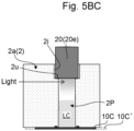
- the enzyme reactor 100 of the first example further includes an anodic electrode 10A arranged in the anode chamber 2A to be immersed in the anodic electrolytic solution LA and a cathodic electrode 10C arranged in the photocatalytic reaction chamber 2P to be immersed in the cathodic electrolytic solution LC.
- the cathodic electrode 10C includes a cathode substrate 10Ca and a photocatalyst layer 10Cp including a photocatalyst formed on a surface of the cathode substrate 10Ca.
- the enzyme reactor 100 of the first example further includes an external circuit 30 including a wiring 12. The wiring 12 electrically connects the anodic electrode 10A to the cathodic electrode 10C.
- the enzyme reactor 100 of the first example further includes a light source 20 and a power supply for light source (not illustrated).
- the light source 20 is disposed in the photocatalytic reaction chamber 2P such that the light source 20 is immersed in the cathodic electrolytic solution LC and faces the cathodic electrode 10C along a depth direction of the reaction vessel 2.
- the power supply for light source is disposed outside the reaction vessel 2 and connected to the light source 20.
- a halogen lamp or a LED light having an electronically excited characteristic wavelength of the photocatalyst layer 10Cp is employed.
- electric power supplied from the power supply for light source to the light source 20 allows the light source 20 to irradiate the photocatalyst layer 10Cp on the cathodic electrode 10C with, for example, a light in a wavelength band from 350 nm to 3500 nm through the cathodic electrolytic solution LC.
- the excited electrons (e - ) are generated on the photocatalyst layer 10Cp of the cathodic electrode 10C, and a reduction reaction represented in Reaction formula (1-1) below is performed in a vicinity of the cathodic electrode 10C in the cathodic electrolytic solution LC.
- this reduction reaction first, the protons (H + ) contained in the cathodic electrolytic solution LC are reduced by the excited electrons (e - ), hydride ions (H - ) are generated, and then, an oxidation type electron mediator (NADP + ) is reduced by the hydride ions (H - ) to produce the reduction type electron mediator (NADPH).
- an oxidizing reaction represented in Reaction formula (1-2) below is performed in a vicinity of the anodic electrode 10A in the anodic electrolytic solution LA.
- the hydroxide ions (OH - ) lose the electrons, and water (H 2 O) and oxygen (O 2 ) are produced.
- the reduction type electron mediator (NADPH) generated in the above-described reduction reaction and the protons (H + ) remaining in the reduction reaction are transferred to the enzyme reaction solution LE of the enzymatic reaction chamber 2E by permeating through the semipermeable membrane 6.
- the biochemical reaction illustrated in Reaction formula (1-3) below occurs in the enzyme reaction solution LE as illustrated in Fig. 1 .
- the enzyme (HMGR) functions as a reductase
- the reduction type electron mediator (NADPH) functions as a coenzyme that imparts energy, thereby reducing the raw material substrate [a] (HMG-CoA).
- NADPH reduction type electron mediator
- the cover portion 5C of the dialysis cup 5 is opened and the substance [b] (mevalonate) and the substance [c] (coenzyme A) are recovered from the enzyme reaction solution LE inside the dialysis cup 5.
- the oxidation type electron mediator (NADP + ) in the enzyme reaction solution LE inside the dialysis cup 5 is transferred to the cathodic electrolytic solution LC of the photocatalytic reaction chamber 2P by permeating through the semipermeable membrane 6, and is reduced again by the above-describe reduction reaction.
- the cathode chamber 2C is partitioned into the photocatalytic reaction chamber 2P and the enzymatic reaction chamber 2E by the semipermeable membrane 6 that allows the oxidation type electron mediator (NADP + ), the reduction type electron mediator (NADPH), and the protons (H + ) to permeate through the membrane 6 and does not allow the enzyme (HMGR) to permeate through the membrane 6.
- NADP + oxidation type electron mediator
- NADPH reduction type electron mediator
- H + protons
- the photocatalytic reaction chamber 2P houses the cathodic electrolytic solution LC in which the oxidation type electron mediator (NADP + ) is dissolved in the common electrolytic solution, and the enzymatic reaction chamber 2E houses the enzyme reaction solution LE in which the enzyme (HMGR) and the raw material substrate [a] (HMG-CoA) are added to the common electrolytic solution. For this reason, irradiation of the photocatalyst layer 10Cp of the cathodic electrode 10C with light allows the reduction reaction and a biochemical reaction (enzymatic reaction) to be linked and performed.
- HMGR oxidation type electron mediator
- the oxidation type electron mediator (NADP + ) is reduced by a reducing action with a photocatalyst in the cathodic electrolytic solution LC to form the reduction type electron mediator (NADPH).
- NADP + oxidation type electron mediator
- NADPH reduction type electron mediator
- the substance [b] (mevalonate) is generated from the raw material substrate [a] (HMG-CoA) using the reduction type electron mediator (NADPH) as a coenzyme in the enzyme reaction solution LE.
- the use of the energy generated by irradiating the photocatalyst with light allows performing the process in which the reduction reaction for reducing the oxidation type electron mediator and the biochemical reaction (enzymatic reaction) for generating a substance using the reduction type electron mediator are linked, thus allowing the substance [b] having a high added value to be produced.
- the cathode chamber 2C were not partitioned by the semipermeable membrane 6 into the photocatalytic reaction chamber 2P and the enzymatic reaction chamber 2E and the entire cathode chamber 2C housed the cathodic electrolytic solution LC, in which the oxidation type electron mediator (NADP + ) were dissolved in the electrolytic solution while the enzyme (HMGR) and the raw material substrate [a] (HMG-CoA) were added to the electrolytic solution, the enzyme would be attracted to a surface of the photocatalyst layer 10Cp and the enzyme would deteriorate due to a potential difference generated on the surface of the photocatalyst layer 10Cp when the photocatalyst layer 10Cp of the cathodic electrode 10C are irradiated with light, thereby losing its function.
- NADP + oxidation type electron mediator
- HMGR enzyme
- HMG-CoA raw material substrate
- the substance is recovered from the enzyme reaction solution LE inside the dialysis cup 5. Confirming whether or not the substance is the substance [b] (mevalonate) allows confirming whether or not a process in which the reduction reaction and the biochemical reaction are linked has been able to be performed. For this reason, it is possible to search for the optimum condition for performing the process in which the reduction reaction and the biochemical reaction are linked by determining whether or not the process in which the reduction reaction and the biochemical reaction are linked have been able to be performed while adjusting the conditions including the pH, temperature, etc.
- the enzymes having the same name but different origins are also classified as different types.
- the dialysis cup 5 can be mounted on and removed from the reaction vessel 2. Therefore, in a single reaction vessel 2, the plurality of dialysis cups 5 having different types, concentrations, and/or the like of the enzymes in the enzyme reaction solutions LE can be used by placing one another, and an optimum type, concentration, etc. of the enzymes for performing the one-step process can be searched. Therefore, when searching for the optimum type, concentration, etc. of the enzymes, the amount of use of each type of enzyme can be made minute, thus allowing the screening cost to be saved.
- FIG. 2 is a schematic cross-sectional view illustrating the enzyme reactor of the second example according to the first embodiment.
- a configuration of the enzyme reactor of the second example will be described.
- a photocatalyst layer 10Cp' including a photocatalyst is formed on the surface of the cathode substrate 10Ca of the cathodic electrode 10C, which is different from the photocatalyst layer 10Cp in the first example.
- the enzyme reactor 200 of the second example includes a reference electrode 50 and an external circuit 40 including a wiring 12, an external power supply 34, an ammeter 36, and a voltmeter 38, instead of the external circuit 30 included in the enzyme reactor 100 of the first example.
- the wiring 12 electrically connects the anodic electrode 10A to the cathodic electrode 10C.
- the external power supply 34 applies a positive voltage and a negative voltage to the anodic electrode 10A and the cathodic electrode 10C via the wiring 12, respectively.
- the ammeter 36 is connected to the wiring 12 and measures a current flowing between the anodic electrode 10A and the cathodic electrode 10C.
- the reference electrode 50 is arranged so as to be immersed in the cathodic electrolytic solution LC in the vicinity of the cathodic electrode 10C in the photocatalytic reaction chamber 2P, and is connected to a negative electrode of the external power supply 34 by the wiring 12.
- the voltmeter 38 is connected to the reference electrode 50 and the negative electrode of the external power supply 34 by the wiring 12, and measures a potential of the cathodic electrode 10C with respect to a potential of the reference electrode 50.
- the configuration of the enzyme reactor 200 of the second example is similar to the enzyme reactor 100 of the first example except as described above.
- the light source 20 irradiates the photocatalyst layer 10Cp' of the cathodic electrode 10C with light through the cathodic electrolytic solution LC.
- the positive voltage and the negative voltage are respectively applied to the anodic electrode 10A and the cathodic electrode 10C by the external power supply 34.
- the potential of the cathodic electrode 10C with respect to the potential of the reference electrode 50 is set to a predetermined value such that the total voltage of the voltage generated by irradiating the photocatalyst layer 10Cp' with light and the voltage applied by the external power supply 34 is equal to or higher than the voltage required for causing the reduction reaction represented in the above Reaction formula (1-1) to occur.
- the excited electrons (e - ) are generated in the photocatalyst layer 10Cp' of the cathodic electrode 10C, and the reduction reaction represented in the above Reaction formula (1-1) is performed in the vicinity of cathodic electrode 10C in the cathodic electrolytic solution LC, and simultaneously with this reduction reaction, the oxidation reaction represented in the above Reaction formula (1-2) is performed in a vicinity of the anodic electrode 10A in the anodic electrolytic solution LA.
- the reduction type electron mediator (NADPH) and the protons (H + ) are transferred to the enzyme reaction solution LE of the enzymatic reaction chamber 2E by permeating through the semipermeable membrane 6.
- the biochemical reaction (enzymatic reaction) represented in the above Reaction formula (1-3) occurs. This produces the mevalonate ((R)-mevalonate) and the coenzyme A (CoA) as the substance [b] and the substance [c], respectively, while simultaneously producing the oxidation type electron mediator (NADP + ).
- the dialysis cup 5 is removed from the mounting port 2h of the reaction vessel 2, subsequently the cover portion 5C of the dialysis cup 5 is opened, and the substance [b] (mevalonate) and the substance [c] (coenzyme A) are recovered from the enzyme reaction solution LE inside the dialysis cup 5.
- the enzyme reactor 200 of the second example includes the reference electrode 50 and the external circuit 40 including the wiring 12, the external power supply 34, the ammeter 36, and the voltmeter 38, unlike the enzyme reactor 100 of the first example. Therefore, when only the voltage generated by irradiating the photocatalyst layer 10Cp' with light is insufficient as the voltage required for causing the reduction reaction represented in the above-described Reaction formula (1-1) to occur, compensating for the insufficiency by applying a voltage by the external power supply 34 allows producing the high value-added substance [b] from the raw material substrate [a] with the process in which the reduction reaction and the biochemical reaction are linked.
- the total voltage of the voltage generated by irradiating the photocatalyst layer 10Cp' with light and the voltage applied by the external power supply 34 can be set to be equal to or higher than the voltage required for causing the reduction reaction to occur.
- the enzyme reactor 200 of the second example when the light source 20 irradiates the photocatalyst layer 10Cp' of the cathodic electrode 10C with light through the cathodic electrolytic solution LC without applying the voltage by the external power supply 34, measuring the potential of the cathodic electrode 10C with respect to the potential of the reference electrode 50 with the voltmeter 38 allows determining whether the voltage generated by irradiating the photocatalyst layer 10Cp' with light is sufficient as the voltage required for causing the reduction reaction to occur or not from the measured value of the potential.
- FIG. 3 is a schematic cross-sectional view illustrating the enzyme reactor of the third example according to the first embodiment.
- a reaction vessel 2 and a dialysis cup 5 are laterally larger than those of the enzyme reactor 100 of the first example, and a main body portion 5B of the dialysis cup 5 has a quadrangular prism shape.
- the enzyme reactor 300 of the third example further includes a first semipermeable membrane 6a and a second semipermeable membrane 6b that partition the enzymatic reaction chamber 2E inside the dialysis cup 5 into a first enzymatic reaction chamber 2Ea, a second enzymatic reaction chamber 2Eb, and a third enzymatic reaction chamber 2Ec in a direction parallel to a bottom surface of the main body portion 5B.
- the first enzymatic reaction chamber 2Ea and the second enzymatic reaction chamber 2Eb are partitioned by the first semipermeable membrane 6a.
- the second enzymatic reaction chamber 2Eb and the third enzymatic reaction chamber 2Ec are partitioned by the second semipermeable membrane 6b.
- a portion corresponding to the bottom portion of the third enzymatic reaction chamber 2Ec is formed of a third semipermeable membrane 6c, and the other portion is formed of the non-permeable membrane 8.
- a side portion 5s of the main body portion 5B is made of the non-permeable membrane 8.
- a photocatalytic reaction chamber 2P and the first enzymatic reaction chamber 2Ea are partitioned by the bottom portion 5u and the non-permeable membrane 8 of the side portion 5s of the main body portion 5B of the dialysis cup 5.
- a photocatalytic reaction chamber 2P and the second enzymatic reaction chamber 2Eb are partitioned by the non-permeable membrane 8 of the bottom portion 5u of the main body portion 5B of the dialysis cup 5.
- the photocatalytic reaction chamber 2P and the third enzymatic reaction chamber 2Ec are partitioned by the third semipermeable membrane 6c of the bottom portion 5u and the non-permeable membrane 8 of the side portion 5s of the main body portion 5B of the dialysis cup 5.
- the enzyme reactor 300 of the third example includes a first enzyme reaction solution LEa housed in the first enzymatic reaction chamber 2Ea, a second enzyme reaction solution LEb housed in the second enzymatic reaction chamber 2Eb, and a third enzyme reaction solution LEc housed in the third enzymatic reaction chamber 2Ec, instead of the enzyme reaction solution LE housed in the enzymatic reaction chamber 2E.
- the anodic electrolytic solution LA is a predetermined electrolytic solution in which a predetermined electrolyte is dissolved in water.
- the cathodic electrolytic solution LC is obtained by dissolving the oxidation type electron mediator (NADP + ) in the common (same) electrolytic solution with the anodic electrolytic solution LA.
- the first enzyme reaction solution LEa is obtained by adding Acetyl-CoA acetyltransferase (ACAT) as a first enzyme and Acetyl-CoA as a raw material substrate [d] to the common electrolytic solution with the anodic electrolytic solution LA.
- ACAT Acetyl-CoA acetyltransferase
- the second enzyme reaction solution LEb is obtained by adding Hydroxymethylglutaryl-CoA synthase (HMGS) as a second enzyme to the common electrolytic solution with the anodic electrolytic solution LA.
- the third enzyme reaction solution LEc is obtained by adding 3-hydroxy-3-methylglutaryl coenzyme A reductase (HMGR) as a third enzyme to the common electrolytic solution with the anodic electrolytic solution LA.
- HMGS Hydroxymethylglutaryl-CoA synthase
- HMGR 3-hydroxy-3-methylglutaryl coenzyme A reductase
- the common electrolytic solution specifically, for example, a mixed aqueous solution (buffer solution) of a weak acid or a weak base and a salt thereof, pH of which is adjusted within a range near the optimum pH of the first to third enzymes, and the temperature of which is adjusted within the range near the optimum temperature of the first to third enzymes is employed.
- Examples of the optimum electrolytic solution as the above-described mixed aqueous solution (buffer solution) in which the pH is adjusted within the range near the optimum pH and the temperature is adjusted within the range near the optimum temperature include a mixed aqueous solution of, for example, 1 mM of MgCl 2 , 2 mM of KCl, and 50 mM of TrisHCl (pH 7.2).
- the first enzyme reaction solution LEa and the second enzyme reaction solution LEb are in contact with one another via the first semipermeable membrane 6a.
- the second enzyme reaction solution LEb and the third enzyme reaction solution LEc are in contact with one another via the second semipermeable membrane 6b.
- the third enzyme reaction solution LEc and the cathodic electrolytic solution LC are in contact with one another via the third semipermeable membrane 6c.
- the first semipermeable membrane 6a is a membrane that allows the raw material substrate [d] and a substance [f] to be described later to permeate through the membrane, and does not allow the first to third enzymes to permeate through the membrane.
- the second semipermeable membrane 6b is a membrane that allows a substance [g] to be described later to permeate through the membrane and does not allow the first to third enzymes to permeate through the membrane.
- the third semipermeable membrane is a membrane that allows the oxidation type electron mediator (NADP + ), the reduction type electron mediator (NADPH) that is the oxidation type electron mediator (NADP + ) having undergone the reduction, and the protons (H + ) to permeate through the membrane and does not allow the first to third enzymes to permeate through the membrane.
- the non-permeable membrane 8 is a membrane that does not allow any component of the cathodic electrolytic solution LC and the first to third enzyme reaction solutions to permeate through the membrane.
- the enzyme reactor 300 of the third example includes the reference electrode 50 and the external circuit 40 including the wiring 12, the external power supply 34, the ammeter 36, and the voltmeter 38, instead of the external circuit 30 included in the enzyme reactor 100 of the first example.
- the configurations of the wiring 12, the external power supply 34, the ammeter 36, and the voltmeter 38 of the external circuit 40, and the reference electrode 50 are similar to those of the enzyme reactor 200 of the second example.
- the configuration of the enzyme reactor 300 of the third example is similar to the enzyme reactor 100 of the first example except as described above.
- the light source 20 irradiates the photocatalyst layer 10Cp of the cathodic electrode 10C with light through the cathodic electrolytic solution LC.
- the positive voltage and the negative voltage are respectively applied to the anodic electrode 10A and the cathodic electrode 10C by the external power supply 34.
- the potential of the cathodic electrode 10C with respect to the potential of the reference electrode 50 is set to a predetermined value such that the total voltage of the voltage generated by irradiating the photocatalyst layer 10Cp with light and the voltage applied by the external power supply 34 is equal to or higher than the voltage required for causing the reduction reaction represented in the above Reaction formula (1-1) to occur.
- the excited electrons (e - ) are generated in the photocatalyst layer 10Cp of the cathodic electrode 10C, and the reduction reaction represented in the above Reaction formula (1-1) is performed in the vicinity of the cathodic electrode 10C in the cathodic electrolytic solution LC, and simultaneously with this reduction reaction, the oxidation reaction represented in the above Reaction formula (1-2) is performed in the vicinity of the anodic electrode 10A in the anodic electrolytic solution LA.
- the biochemical reaction represented in Reaction formula (1-4) below occurs in the first enzyme reaction solution LEa, as illustrated in Fig. 3 , prior to and in parallel with the reduction reaction and the oxidation reaction described above.
- the first enzyme ACAT
- the first enzyme ACAT
- the raw material substrate [d] (Acetyl-CoA) and the substance [f] (Acetoacetyl-CoA) in the first enzyme reaction solution LEa are transferred to the second enzyme reaction solution LEb by permeating through the first semipermeable membrane 6a. Consequently, in the second enzyme reaction solution LEb, the biochemical reaction (enzymatic reaction) represented in Reaction formula (1-5) below occurs.
- the second enzyme (HMGS) functions as a reductase to reduce the raw material substrate [d] (Acetyl-CoA) and the substance [f] (Acetoacetyl-CoA).
- HMG-CoA 3-hydroxy-3-methylglutaryl-CoA
- CoA coenzyme A
- the substance [g] (HMG-CoA) in the second enzyme reaction solution LEb is transferred to the third enzyme reaction solution LEc by permeating through the second semipermeable membrane 6b.
- the reduction type electron mediator (NADPH) generated by the reduction reaction represented in the above Reaction formula (1-1) and the protons (H + ) remaining in the reduction reaction are transferred to the third enzyme reaction solution LEc by permeating through the third semipermeable membrane 6c. Consequently, in the third enzyme reaction solution LEc, the biochemical reaction (enzymatic reaction) represented in Reaction formula (1-6) below occurs.
- the third enzyme functions as a reductase and the reduction type electron mediator (NADPH) functions as an energy-imparting coenzyme to reduce the substance [g] (HMG-CoA).
- the reduction type electron mediator (NADPH) is oxidized to produce the oxidation type electron mediator (NADP + ).
- the cover portion 5C of the dialysis cup 5 is opened, and the substance [i] (mevalonate ((R)-mevalonate)) and the substance [j] (coenzyme A (CoA)) are recovered from the third enzyme reaction solution LEc inside the dialysis cup 5.
- the enzymatic reaction chamber 2E is partitioned into the first enzymatic reaction chamber 2Ea, the second enzymatic reaction chamber 2Eb, and the third enzymatic reaction chamber 2Ec in the reaction vessel 2 as a single reaction cell.
- the first enzymatic reaction chamber 2Ea and the second enzymatic reaction chamber 2Eb are partitioned by the first semipermeable membrane 6a that allows the raw material substrate [d] and the substance [f] to permeate through the membrane, and does not allow the first to third enzymes to permeate through the membrane.
- the second enzymatic reaction chamber 2Eb and the third enzymatic reaction chamber 2Ec are partitioned by the second semipermeable membrane 6b that allows the substance [g] to permeate through the membrane and does not allow the first to third enzymes to permeate through the membrane.
- the third enzymatic reaction chamber 2Ec and the photocatalytic reaction chamber 2P are partitioned by the third semipermeable membrane 6c that allows the oxidation type electron mediator (NADP + ), the reduction type electron mediator (NADPH), and the protons (H + ) to permeate through the membrane and does not allow the first to third enzymes to permeate through the membrane.
- the photocatalytic reaction chamber 2P houses the cathodic electrolytic solution LC in which the oxidation type electron mediator (NADP + ) is dissolved in the common electrolytic solution
- the first enzymatic reaction chamber 2Ea houses the first enzyme reaction solution LEa in which the first enzyme (ACAT) and the raw material substrate [d] (Acetyl-CoA) are added to the common electrolytic solution
- the second enzymatic reaction chamber 2Eb houses the second enzyme reaction solution LEb in which the second enzyme (HMGS) is added to the common electrolytic solution
- the third enzymatic reaction chamber 2Ec houses the third enzyme reaction solution LEc in which the third enzyme (HMGR) is added to the common electrolytic solution.
- the biochemical reaction by the first enzyme, the biochemical reaction by the second enzyme, and the biochemical reaction by the third enzyme can be individually performed in the first to third enzymatic reaction chambers. This makes it easy to monitor the individual progress of these biochemical reactions. Therefore, the replacement and addition of the old and new enzymes of the first to third enzymes in the first to third enzymatic reaction chambers can be easily performed based on the monitoring.
- the semipermeable membrane is a membrane that partitions the cathode chamber into the photocatalytic reaction chamber and the enzymatic reaction chamber, allows the reduced electron mediator (the substance which is obtained by reducing the electron mediator) to permeate through the membrane, and does not allow the enzyme to permeate through the membrane.
- the molecular weight cutoff (MWCO) of the semipermeable membrane is not particularly limited as long as the semipermeable membrane has an amount that allows the reduced electron mediator (the substance which is obtained by reducing the electron mediator) to permeate through the membrane and does not allow the enzymes to permeate through the membrane.
- MWCO molecular weight cutoff
- it is preferably within a range of 1000 Da or more and 10000 Da or less. This is because the semipermeable membrane can preferably be a membrane that allows the electron mediator to permeate through the membrane and does not allow the enzymes to permeate through the membrane.
- the material of the semipermeable membrane is not particularly limited, and for example, a porous polymer membrane can be employed.
- a porous polymer membrane can be employed.
- polytetrafluoroethylene is particularly preferable because of its high biocompatibility.
- the anodic electrolytic solution is an electrolytic solution in which an electrolyte is dissolved in a solvent.
- the cathodic electrolytic solution is not particularly limited as long as the cathodic electrolytic solution is obtained by dissolving the electron mediator in the electrolytic solution, but is usually a solution in which the electron mediator is dissolved in the common (same) electrolytic solution with the anodic electrolytic solution.
- the enzyme reaction solution is not particularly limited as long as the enzyme reaction solution is obtained by adding the enzymes and the raw material substrate to a liquid such as water. For example, the enzyme reaction solution is obtained by adding the enzymes and the raw material substrate to the common electrolytic solution with the anodic electrolytic solution.
- the common electrolytic solution employed for the anodic electrolytic solution, the cathodic electrolytic solution, and the enzyme reaction solution is not particularly limited as long as the common electrolytic solution is an electrolytic solution that can link and perform the target reduction reaction in the cathodic electrolytic solution and the target enzyme reaction in the enzyme reaction solution.
- the common electrolytic solution is preferably, for example, an electrolytic solution in which an electrolyte is dissolved in a solvent such as water, and among them, a mixed aqueous solution (buffer solution) of a weak acid or a weak base and a salt thereof, pH of which is adjusted within a range near the optimum pH of the enzyme, and the temperature is adjusted within a range near the optimum temperature of the enzyme.
- the electron mediator contained in the cathodic electrolytic solution is not particularly limited as long as the electron mediator can be reduced by a voltage applied to the cathodic electrode and the reduced electron mediator can be used as a coenzyme in the target enzymatic reaction in the enzyme reaction solution, and examples thereof include nicotinamide adenine dinucleotide phosphate (NADP + ), nicotinamide adenine dinucleotide (NAD + ), and flavin adenine dinucleotide (FAD).
- NADP + nicotinamide adenine dinucleotide phosphate
- NAD + nicotinamide adenine dinucleotide
- FAD flavin adenine dinucleotide
- the concentration [ppm] of the electron mediator in the cathodic electrolytic solution is not particularly limited as long as the target reduction reaction in the cathodic electrolytic solution and the target enzymatic reaction in the enzyme reaction solution can be linked and performed.
- the concentration may be appropriately selected depending on the conditions including the type, etc. of the electrolytic solution, the type, etc. of the reduction reaction, the type, etc. of the electron mediator, the type, etc. of the enzymatic reaction, the type, concentration, etc. of the enzymes, the type, concentration, etc. of the substrate, and the like.
- the enzyme contained in the enzyme reaction solution is not particularly limited as long as the enzyme is a molecule which functions as a catalyst for the target enzyme reaction in the enzyme reaction solution, and the enzyme may be appropriately selected according to the target enzyme reaction in the enzyme reaction solution.
- the enzyme include an oxidoreductase, a transferase, a hydrolase, a lyase, an isomerase, and a ligase (synthase), and among them, for example, an enzyme using the electron mediator as the coenzyme contained in the cathodic electrolytic solution is preferred.
- the concentration [U/mL] of the enzyme in the enzyme reaction solution is not particularly limited as long as the target reduction reaction in the cathodic electrolytic solution and the target enzyme reaction in the enzyme reaction solution are allowed to be linked and performed.
- the concentration may be appropriately selected according to the condition including the type, etc. of the electrolytic solution, the type, etc. of the reduction reaction, the type, concentration, etc. of the electron mediator, the type, etc. of the enzyme reaction, the type, etc. of the enzyme, and the type, concentration, etc. of the substrate, and the like.
- the raw material substrate contained in the enzyme reaction solution is not particularly limited as long as the raw material substrate is a chemical species that serves as a raw material for the substance generated by the target enzyme reaction in the enzyme reaction solution and the raw material substrate is a substance that causes the enzyme reaction of the substance to be catalyzed by the enzyme, and the raw material substrate may be appropriately selected according to the target enzyme reaction in the enzyme reaction solution.
- the concentration [mol/mL] of the raw material substrate in the enzyme reaction solution is not particularly limited as long as the target reduction reaction in the cathodic electrolytic solution and the target enzyme reaction in the enzyme reaction solution are allowed to be linked and performed.
- the concentration may be appropriately selected according to the conditions including the type, etc. of the electrolytic solution, the type, etc. of the reduction reaction, the type, concentration, etc. of the electron mediator, the type, etc. of the enzyme reactions, the type, concentration, etc. of the enzymes, the type, etc. of the substrate.
- the anodic electrode is arranged in the anode chamber so as to be immersed in the anodic electrolytic solution.
- the material of the anodic electrode is not particularly limited as long as the material has a conductivity and does not deteriorate in the oxidation reaction occurring in the vicinity of the anodic electrode. Examples thereof include a metal substrate, a glass substrate, and the like, and among them, a metal substrate and the like made of platinum, gold, silver, copper, titanium, and the like are preferred.
- the cathodic electrode is arranged in the photocatalytic reaction chamber so as to be immersed in the cathodic electrolytic solution, and has a photocatalyst layer containing a photocatalyst on a surface thereof.
- the cathodic electrode preferably includes, for example, a cathode substrate and a photocatalyst layer formed on a surface of the cathode substrate.
- the material of the cathode substrate is not particularly limited as long as the material has a conductivity and does not deteriorate in the reduction reaction occurring in the vicinity of the cathodic electrode. Examples thereof include a metal substrate, a glass substrate, and the like, and among them, a metal substrate and the like made of platinum, gold, silver, copper, titanium, and the like are preferred.
- the photocatalyst layer includes a photocatalyst, thus generates the excited electrons (e - ) by being irradiated with light, and exhibits the reducing action.
- the photocatalyst layer is not particularly limited as long as the photocatalyst layer contains a photocatalyst.
- the photocatalyst layer containing a co-catalyst supported on the photocatalyst in addition to the photocatalyst is preferred.
- the material of the photocatalyst include metal oxides, such as transition-metal oxides, and among them, BiVO 4 , SrTiO 3 , NaTaO 3 , WO 3 , Cu oxides, and the like are preferred.
- Preferable examples of the material of the co-catalyst includes CoO, NiO, FeO, Y 2 O 3 , Rh, Ru, Ir, and CoP x .
- the ion exchange membrane partitions the inside of the reaction vessel into the anode chamber and the cathode chamber, and allows only predetermined ions contained in the electrolytic solution to permeate through the membrane.
- the ion exchange membrane is not particularly limited, and for example, the proton exchange membrane and the like that allows only the protons (H + ) to permeate through the membrane and does not allow other substances to permeate through the membrane is preferred.
- the material of the proton exchange membrane is not particularly limited and may be appropriately selected according to the various conditions. Examples of the material include Nafion (registered trademark) and the like.
- the enzyme reactor according to the first embodiment includes: the reaction vessel; the ion exchange membrane; the semipermeable membrane; the anodic electrolytic solution; the cathodic electrolytic solution; the enzyme reaction solution; the anodic electrode; and the cathodic electrode.
- the cathodic electrolytic solution and the enzyme reaction solution are in contact via the semipermeable membrane.
- the enzyme reactor according to the first embodiment is not particularly limited as long as the enzyme reactor is as described above, but usually further includes a light source capable of irradiating the photocatalyst layers of the cathodic electrode with light, similarly to the first example to the third example.
- the light source is not particularly limited as long as the light source generates a voltage by irradiating the photocatalyst layer with light, and examples thereof include halogen lamps, LED lamps, and natural lights.
- the enzyme reactor preferably further includes the reference electrode arranged so as to be immersed in the cathodic electrolytic solution in the vicinity of the cathodic electrode in the photocatalytic reaction chamber and is capable of measuring the potential of the cathodic electrode with respect to the potential of the reference electrode. This is because it is possible to determine whether or not the voltage generated by irradiating the photocatalyst layer with light is sufficient as the voltage required for causing the reduction reaction to occur.
- the enzyme reactor preferably further includes the external power supply that applies the positive voltage and the negative voltage to the anodic electrode and the cathodic electrode, respectively. This is because, when the voltage generated by irradiating the photocatalyst layer with light alone is insufficient as the voltage required for causing the reduction reaction to occur, compensating for the insufficiency by applying the voltages by the external power supply allows the process in which the reduction reaction and the enzyme reaction are linked to be performed.
- the enzyme reactor includes the dialysis cup and the mounting port that allows mounting and removing of the dialysis cup at a portion of the cathode chamber side in the upper portion of the reaction vessel.
- a part of the dialysis cup is preferred to be the semipermeable membrane that partitions the cathode chamber into the photocatalytic reaction chamber and the enzymatic reaction chamber. This is because, in the single reaction vessel, the plurality of dialysis cups having different types, concentrations, and/or the like of the enzymes in the enzyme reaction solutions can be used by replacing one another, and the optimum type, concentration, and the like of the enzymes for performing the process in which the reduction reaction and the enzyme reaction are linked can be searched.
- the enzymatic reaction chamber is partitioned and multi-layered into the plurality of enzymatic reaction chambers by the one or more semipermeable membranes, the plurality of types of enzyme reaction solutions housed in the respective plurality of enzymatic reaction chambers contain the enzymes, and at least one of the plurality of types of enzyme reaction solutions further contains the raw material substrate. This is because, the multi-stage enzymatic reaction is allowed.
- the enzyme reactor is preferred to be a device in which the cathode solution housed in the photocatalytic reaction chamber and the plurality of types of the enzyme reaction solutions housed in the respective plurality of the enzymatic reaction chambers are in contact with one another via the semipermeable membranes according to the designs of the reaction pathway.
- the electron mediator intercommunicates through the plurality of transfer paths between the cathode solution and the plurality of types of enzyme reaction solutions, which allows the multi-stage enzymatic reaction with the electron mediator functioning as a coenzyme and allows producing the higher value-added substance.
- the enzyme reactor is preferred to be a device in which the reaction pathway is configured to be a desired pathway by especially configuring the permeabilities of the raw material substrate and the respective plurality of substances produced by the enzymatic reactions at the plurality of enzymatic reaction chambers for the semipermeable membrane between the photocatalytic reaction chamber and the enzymatic reaction chambers and the one or more semipermeable membrane between the plurality of enzymatic reaction chambers. This is because the complicated reaction pathway is allowed.
- the enzyme reactor is preferred to be a device in which the semipermeable membrane between the photocatalytic reaction chamber and the enzymatic reaction chamber and the one or more semipermeable membrane between the plurality of the enzymatic reaction chamber have different amounts (for example, different amounts within the range of 1000 Da or more and 10000 Da or less) of molecular weight cutoff (MWCO).
- MWCO molecular weight cutoff
- the enzyme reactor according to the first embodiment is used in the method for producing the substance from the raw material substrate by irradiating the photocatalyst layer of the cathodic electrode with light to allow the reduction reaction (sometimes referred to as “target reduction reaction in the cathodic electrolytic solution” in the first embodiment) in which the electron mediator is reduced in the cathodic electrolytic solution and the enzyme reaction (sometimes referred to as “target enzyme reaction in the enzyme reaction solution” in the first embodiment) in which the enzyme is caused to function in the enzyme reaction solution and the electron mediator reduced by the reduction reaction is used as the coenzyme to produce the substance from the raw material substrate, to be linked and performed.
- the reduction reaction sometimes referred to as "target reduction reaction in the cathodic electrolytic solution” in the first embodiment
- the enzyme reaction sometimes referred to as “target enzyme reaction in the enzyme reaction solution” in the first embodiment
- the enzyme is caused to function in the enzyme reaction solution and the electron mediator reduced by the reduction reaction is used as the coenzyme to produce the substance from the raw material substrate,
- the use of the enzyme reactor is not particularly limited as long as the use is the method for producing the substance, but it may be a method for producing a substance from a raw material substrate by, for example, performing a reduction reaction and a biochemical reaction (enzymatic reaction) in a linked manner.
- An enzyme reactor includes a reaction vessel; an ion exchange membrane that partitions an inside of the reaction vessel into an anode chamber and a cathode chamber; a semipermeable membrane that partitions the cathode chamber into a photocatalytic reaction chamber and an enzymatic reaction chamber; an anodic electrolytic solution housed in the anode chamber; a cathodic electrolytic solution housed in the photocatalytic reaction chamber; an enzyme reaction solution housed in the enzymatic reaction chamber; an anodic electrode disposed in the anode chamber so as to be immersed in the anodic electrolytic solution; and a cathodic electrode disposed in the photocatalytic reaction chamber so as to be immersed in the cathodic electrolytic solution.
- the cathodic electrode has a surface on which a photocatalyst layer containing a photocatalyst is disposed.
- the cathodic electrolytic solution contains carbon dioxide.
- the enzyme reaction solution contains an enzyme.
- the cathodic electrolytic solution and the enzyme reaction solution are in contact with one another via the semipermeable membrane.
- the semipermeable membrane allows the reduced carbon dioxide to permeate through the semipermeable membrane and does not allow the enzyme to permeate through the semipermeable membrane.
- Fig. 4 is a schematic cross-sectional view illustrating the enzyme reactor of the fourth example according to the second embodiment.
- an anodic electrolytic solution LA is the predetermined electrolytic solution in which the predetermined electrolyte is dissolved in water.
- a cathodic electrolytic solution LC is the solution in which the carbon dioxide (CO 2 ) is dissolved in the common (same) electrolytic solution with the anodic electrolytic solution LA.
- An enzyme reaction solution LE is obtained by adding formate-tetrahydrofolate ligase (FTL) as an enzyme, adding Tetrahydrofolic acid (THF) as a raw material substrate [k], and adding adenosine triphosphate (ATP) to the common electrolytic solution with the anodic electrolytic solution LA.
- FTL formate-tetrahydrofolate ligase
- THF Tetrahydrofolic acid
- ATP adenosine triphosphate
- the common electrolytic solution for example, a mixed aqueous solution (buffer solution) of a weak acid or a weak base and a salt thereof, pH of which is adjusted within a range near the optimum pH of the enzyme (FTL), and the temperature is adjusted within a range near the optimum temperature of the enzyme (FTL) is used.
- the anodic electrolytic solution LA and the cathodic electrolytic solution LC are in contact with one another via the proton exchange membrane 4.
- the cathodic electrolytic solution LC and the enzyme reaction solution LE are in contact with one another via the semipermeable membrane 6.
- the semipermeable membrane 6 is a membrane that allows formic acid (HCOOH) which is obtained by reducing carbon dioxide (CO 2 ) to permeate through the membrane and does not allow enzyme (FTL) to permeate through the membrane.
- the semipermeable membrane 6 be a membrane that allows formic acid (HCOOH) to permeate through the membrane and does not allow enzyme (FTL), the raw material substrate [k], ATP, a substance [m] and a substance [n] to be described later, and ADP to be described later to permeate through the membrane. This is because formation of the substance [m] and the substance [n] is likely to occur, and a recovery of the substance [m] and the substance [n] is facilitated.
- HCOOH formic acid
- FTL enzyme
- the raw material substrate [k], ATP, the substance [m] and the substance [n] to be described later, and ADP to be described later are not significantly higher than that of formic acid (HCOOH) and an appropriate semipermeable membrane cannot be selected, the raw material substrate [k], the ATP, the substance [m] and the substance [n] to be described later, and the ADP to be described later become diffused into both the cathodic electrolytic solution LC and the enzyme reaction solution LE.
- the reduction reaction and the biochemical reaction enzyme reaction
- the enzyme reactor 400 of the fourth example includes the reference electrode 50 and the external circuit 40 including the wiring 12, the external power supply 34, the ammeter 36, and the voltmeter 38, instead of the external circuit 30 included in the enzyme reactor 100 of the first example according to the first embodiment.
- the configurations of the wiring 12, the external power supply 34, the ammeter 36, and the voltmeter 38 of the external circuit 40 and the reference electrode 50 are similar to those of the enzyme reactor 200 of the second example according to the first embodiment.
- the enzyme reactor 400 of the fourth example includes a carbon dioxide feeder 51 and a gas introduction pipe 52.
- One end of the gas introduction pipe 52 is connected to the carbon dioxide feeder 51, and the other end of the gas introduction pipe 52 is immersed in the cathodic electrolytic solution LC.
- the carbon dioxide feeder 51 feeds carbon dioxide (CO 2 ) gas to the cathodic electrolytic solution LC through the gas introduction pipe 52.
- CO 2 carbon dioxide
- a configuration of the enzyme reactor 400 of the fourth example is similar to that of the enzyme reactor 100 of the first example according to the first embodiment, except as described above.
- the positive voltage and the negative voltage are respectively applied to the anodic electrode 10A and the cathodic electrode 10C by the external power supply 34.
- the potential of the cathodic electrode 10C with respect to the potential of the reference electrode 50 is set to a predetermined value such that the total voltage of the voltage generated by irradiating the photocatalyst layer 10Cp with light and the voltage applied by the external power supply 34 is equal to or higher than the voltage required for causing the reduction reaction represented in Reaction formula (2-1) below to occur.
- the excited electrons (e - ) are generated on the photocatalyst layer 10Cp of the cathodic electrode 10C, and the reduction reaction represented in Reaction formula (2-1) below is performed in the vicinity of the cathodic electrode 10C in the cathodic electrolytic solution LC.
- the reduction reaction first, the protons (H + ) contained in the cathodic electrolytic solution LC are reduced by the excited electrons (e - ), hydride ions (H - ) are generated, and then, carbon dioxide (CO 2 ) is reduced by the hydride ions (H - ) to produce formic acid (HCOOH).
- an oxidizing reaction represented in Reaction formula (2-2) below occurs in the vicinity of the anodic electrode 10A in the anodic electrolytic solution LA.
- hydroxide ions (OH - ) lose the electrons, and water (H 2 O) and oxygen (O 2 ) are formed.
- formic acid (HCOOH) produced by the above-described reduction is transferred to the enzyme reaction solution LE of the enzymatic reaction chamber 2E by permeating through the semipermeable membrane 6.
- the cover portion 5C of the dialysis cup 5 is opened, and the substance [m] (10-Formyl-THF), the substance [n] (orthophosphate), and adenosine diphosphate (ADP) are recovered from the enzyme reaction solution LE inside the dialysis cup 5.
- the cathode chamber 2C is partitioned into the photocatalytic reaction chamber 2P and the enzymatic reaction chamber 2E by the semipermeable membrane 6, which allows formic acid (HCOOH) to permeate through the membrane and does not allow enzyme (FTL) to permeate through the membrane.
- the photocatalytic reaction chamber 2P houses the cathodic electrolytic solution LC in which carbon dioxide (CO 2 ) is dissolved in the common electrolytic solution
- the enzymatic reaction chamber 2E houses the enzyme reaction solution LE in which enzyme (FTL), the raw material substrate [k] (THF), and adenosine triphosphate (ATP) are added to the common electrolytic solution.
- irradiating the photocatalyst layer 10Cp of the cathodic electrode 10C with light and applying a voltage with the external power supply 34 at the same time allows a reduction reaction in which carbon dioxide (CO 2 ) is reduced to produce formic acid (HCOOH) by the reduction action of the photocatalyst and the like in the cathodic electrolytic solution LC and a biochemical reaction (enzymatic reaction) in which the substance [m] (10-Formyl-tetrahydrofolate) is generated using the raw material substrate [k] (THF) and formic acid (HCOOH) in the enzyme reaction solution LE to be linked and performed.
- CO 2 carbon dioxide
- HCOOH formic acid
- the use of the energy of the voltage applied by the external power supply together with the energy generated by irradiating the photocatalyst with light allows performing the process in which the reduction reaction for reducing the carbon dioxide and the biochemical reaction (enzymatic reaction) for generating a substance using the formic acid which is obtained by reducing carbon dioxide (CO 2 ) are linked, which allows producing the high value-added substance [m].
- the semipermeable membrane is a membrane that partitions the above-described cathode chamber into the photocatalytic reaction chamber and the enzymatic reaction chamber, and allows the reduced carbon dioxide (the substance which is obtained by reducing carbon dioxide) to permeate through the membrane and does not allow the enzyme to permeate through the membrane.
- the molecular weight cutoff (MWCO) of the semipermeable membrane is not particularly limited as long as the semipermeable membrane allows the reduced carbon dioxide to permeate through the membrane and does not allow the enzyme to permeate through the membrane.
- MWCO molecular weight cutoff
- the material of the semipermeable membrane is the same as the material of the semipermeable membrane according to the first embodiment, and therefore, the explanation thereof will be omitted.
- the anodic electrolytic solution is an electrolytic solution in which an electrolyte is dissolved in a solvent.
- the cathodic electrolytic solution is not particularly limited as long as the cathodic electrolytic solution is an electrolytic solution in which a carbon dioxide is dissolved in the electrolytic solution. However, the cathodic electrolytic solution is usually an electrolytic solution in which a carbon dioxide is dissolved in the common (same) electrolytic solution with the anodic electrolytic solution.
- the enzyme reaction solution is not particularly limited as long as the enzyme reaction solution is a solution in which an enzyme is added to a liquid such as water.
- the enzyme reaction solution is, for example, a solution in which an enzyme is added to the common electrolytic solution with the anodic electrolytic solution.
- the common electrolytic solution used for the anodic electrolytic solution, the cathodic electrolytic solution, and the enzyme reaction solution is not particularly limited as long as the common electrolytic solution is an electrolytic solution that allows a target reduction reaction in the cathodic electrolytic solution and a target enzyme reaction in the enzyme reaction solution to be linked and performed.
- the common electrolytic solution is, for example, an electrolytic solution in which an electrolyte is dissolved in water (solvent), and among them, a mixed aqueous solution (buffer solution) of a weak acid or a weak base and a salt thereof, pH of which is adjusted within a range near the optimum pH of the enzyme, and a temperature is adjusted within a range near the optimum temperature of the enzyme.
- the concentration [ppm] of carbon dioxide in the cathodic electrolytic solution is not particularly limited as long as the concentration allows the target reduction reaction in the cathodic electrolytic solution and the target enzyme reaction in the enzyme reaction solution to be linked and performed.
- the concentration may be appropriately selected according to the type, etc. of the electrolytic solution, the type, etc. of the enzyme reaction, and the type, concentration, etc. of the enzyme.
- the enzyme contained in the enzyme reaction solution is not particularly limited as long as the enzyme is a molecule which functions as a catalyst for the target enzyme reaction in the enzyme reaction solution, and the enzyme may be appropriately selected according to the target enzyme reaction in the enzyme reaction solution.
- the enzyme include an oxidoreductase, a transferase, a hydrolase, a lyase, an isomerase, and a ligase (synthase), and among them, for example, an enzyme using the electron mediator as the coenzyme contained in the cathodic electrolytic solution is preferred.
- the concentration [U/mL] of the enzyme in the enzyme reaction solution is not particularly limited as long as the concentration allows the target reduction reaction in the cathodic electrolytic solution and the target enzyme reaction in the enzyme reaction solution to be linked and performed.
- the concentration may be appropriately selected according to the conditions including the type, etc. of the electrolytic solution, the concentration, etc. of carbon dioxide, the type, etc. of the enzyme reaction, and the type, concentration, etc. of the enzyme.
- the anodic electrode and the cathodic electrode are the same as those of the anodic electrode and the cathodic electrode according to the first embodiment, and therefore will not be described here.
- the ion exchange membrane is the same as the ion exchange membrane according to the first embodiment, and therefore will not be described here.
- the enzyme reactor according to the second embodiment includes: the reaction vessel; the ion exchange membrane; the semipermeable membrane; the anodic electrolytic solution; the cathodic electrolytic solution; the enzyme reaction solution; the anodic electrode; and the cathodic electrode.
- the cathodic electrolytic solution and the enzyme reaction solution are in contact via the semipermeable membrane.
- the enzyme reactor according to the second embodiment is not particularly limited as long as the enzyme reactor is as described above.
- the enzyme reactor usually further includes a light source similarly to the enzyme reactor according to the first embodiment.
- the light source is the same as the enzyme reactor according to the first embodiment.
- the enzyme reactor further includes a reference electrode, and is preferably a device capable of measuring the potential of the cathodic electrode with respect to the potential of the reference electrode.
- the enzyme reactor preferably further includes an external power supply.
- the enzyme reactor includes the dialysis cup and the mounting port that allows mounting and removing of the dialysis cup at a portion of the cathode chamber side in the upper portion of the reaction vessel.
- a part of the dialysis cup is preferred to be the semipermeable membrane that partitions the cathode chamber into the photocatalytic reaction chamber and the enzymatic reaction chamber.
- the enzymatic reaction chamber is partitioned and multi-layered into the plurality of enzymatic reaction chambers by the one or more semipermeable membranes, the plurality of types of enzyme reaction solutions housed in the respective plurality of enzymatic reaction chambers contain the enzymes. This is because the multi-stage enzymatic reaction is allowed.
- the enzyme reactor is preferred to be a device in which the reaction pathway is configured to be a desired pathway by configuring the permeabilities of the respective plurality of substances produced by the enzymatic reactions at the plurality of enzymatic reaction chambers for the semipermeable membrane between the photocatalytic reaction chamber and the enzymatic reaction chambers and the one or more semipermeable membrane between the enzymatic reaction chambers. This is because the complicated reaction pathway is allowed.
- the enzyme reactor is preferred to be a device in which the semipermeable membrane between the photocatalytic reaction chamber and the enzymatic reaction chamber and the one or more semipermeable membrane between the plurality of the enzymatic reaction chamber have different amounts (for example, different amounts within the range of 1000 Da or more and 10000 Da or less) of molecular weight cutoff (MWCO).
- MWCO molecular weight cutoff
- the enzyme reactor according to the second embodiment is used in the method for producing the substance from the carbon dioxide by irradiating the photocatalyst layer of the cathodic electrode with light to allows the reduction reaction (sometimes referred to as “target reduction reaction in the cathodic electrolytic solution” in the second embodiment) in which the carbon dioxide is reduced in the cathodic electrolytic solution and the enzyme reaction (sometimes referred to as “target enzyme reaction in the enzyme reaction solution” in the second embodiment) in which the enzyme is caused to function in the enzyme reaction solution to produce the substance from the reduced carbon dioxide (the substance which is obtained by reducing carbon dioxide), to be linked and performed.
- the reduction reaction sometimes referred to as "target reduction reaction in the cathodic electrolytic solution” in the second embodiment
- the enzyme reaction sometimes referred to as “target enzyme reaction in the enzyme reaction solution” in the second embodiment
- the enzyme is caused to function in the enzyme reaction solution to produce the substance from the reduced carbon dioxide (the substance which is obtained by reducing carbon dioxide), to be linked and performed.
- Fig. 5A is a photograph illustrating an overall outline of the enzyme reactor of Example 1.
- Fig. 5BA is a top view schematically illustrating a main part of the enzyme reactor of Example 1.
- Fig. 5BB is a cross-sectional view schematically illustrating a main part of the enzyme reactor of Example 1 and is a diagram illustrating a cross-section along the A-A' line of Fig. 5BA .
- Fig. 5BC is a cross-sectional view schematically illustrating a main part of the enzyme reactor of Example 1 and is a diagram illustrating a cross-section along the B-B' line of Fig. 5BA .
- an enzyme reactor 500 of Example 1 includes the reaction vessel 2 including a first member 2a, a second member 2b, and a third member 2c; a proton exchange membrane (ion exchange membrane) 4; and a dialysis cup 5.
- the first member 2a and the second member 2b of the reaction vessel 2 are fastened by bolts 2v inserted into bolt insertion holes 2ah of the first member 2a and bolt insertion holes 2bh of the second member 2b.
- the first member 2a and the third member 2c of the reaction vessel 2 are fastened by bolts 2v inserted into bolt insertion holes 2ah of the first member 2a and bolt insertion holes 2ch of the third member 2c.
- the proton exchange membrane 4 is fixed to the first member 2a side of the second member 2b, and partitions an inside 2N of the reaction vessel 2 into an anode chamber 2A and a cathode chamber 2C.
- the mounting port (opening) 2h having the same shape and size in plan view as those of the bottom portion 5u of the main body portion 5B of the dialysis cup 5 is provided on an upper portion 2at of the first member 2a.
- the dialysis cup 5 includes the cylindrical main body portion 5B, which includes a bottom portion 5u and a side portion 5s and is provided with an opening portion 5h on an upper portion thereof facing the bottom portion 5u, and a cover portion 5C (which is closed in the figure) provided to allow opening and closing the opening portion 5h of the main body portion 5B.
- the cover portion 5C includes a protruding portion 5p protruding laterally with respect to the side portion 5s of the main body portion 5B.
- the dialysis cup 5 is mounted on the mounting port 2h of the first member 2a by inserting the main body portion 5B into the cathode chamber 2C through mounting port 2h of the first member 2a and supporting the protruding portion 5p of the cover portion 5C at a periphery portion of the mounting port 2h on the upper portion 2at of the first member 2a.
- the dialysis cup 5 is allowed to be mounted on and removed from the mounting port 2h of the first member 2a.
- the bottom portion 5u of the main body portion 5B of the dialysis cup 5 is made of a semipermeable membrane 6, and the side portion 5s of the main body portion 5B is made of a non-permeable membrane 8.
- the cathode chamber 2C is partitioned into a photocatalytic reaction chamber 2P outside the dialysis cup 5 and an enzymatic reaction chamber 2E inside the dialysis cup 5 by the semipermeable membrane 6 of the bottom portion 5u and the non-permeable membrane 8 of the side portion 5s of the main body portion 5B of the dialysis cup 5.
- the enzyme reactor 500 further includes an anodic electrolytic solution LA housed in the anode chamber 2A, a cathodic electrolytic solution LC housed in the photocatalytic reaction chamber 2P of the cathode chamber 2C, and an enzyme reaction solution LE housed in the enzymatic reaction chamber 2E of the cathode chamber 2C.
- the anodic electrolytic solution LA is a predetermined electrolytic solution in which a predetermined electrolyte is dissolved in water.
- the cathodic electrolytic solution LC is a solution of the electron mediator dissolved in the common (same) electrolytic solution with the anodic electrolytic solution LA.
- the enzyme reaction solution LE is obtained by adding an enzyme and a raw material substrate to a common electrolytic solution with the anodic electrolytic solution LA.
- the common electrolytic solution specifically, for example, a mixed aqueous solution (buffer solution) of a weak acid or a weak base and a salt thereof, pH of which is adjusted within a range near the optimum pH of the enzyme, and the temperature is adjusted within a range near the optimum temperature of the enzyme, is employed.
- the anodic electrolytic solution LA and the cathodic electrolytic solution LC are in contact with one another via the proton exchange membrane 4.
- the cathodic electrolytic solution LC and the enzyme reaction solution LE are in contact with one another via the semipermeable membrane 6.
- the semipermeable membrane 6 is a membrane that allows the reduced electron mediator (the substance which is obtained by reducing the electron mediator) to permeate through the membrane and does not allow the enzyme to permeate through the membrane.
- the non-permeable membrane 8 is a membrane that does not allow any component of the cathodic electrolytic solution LC or the enzyme reaction solution LE to permeate through the membrane.
- the enzyme reactor 500 further includes an anodic electrode 10A arranged in the anode chamber 2A to be immersed in the anodic electrolytic solution LA and a cathodic electrode 10C.
- the cathodic electrode 10C includes a cathode substrate made of a copper substrate and a photocatalyst layer formed on an upper surface of the cathode substrate.
- the cathodic electrode 10C is fixed between the first member 2a and the third member 2c, and is disposed on the photocatalytic reaction chamber 2P such that the upper surface of the photocatalyst layer is immersed in the cathodic electrolytic solution LC.
- the enzyme reactor 500 further includes an external circuit (illustrated in Fig. 5D and Fig. 5E below) including a wiring.
- the enzyme reactor 500 further includes a light source 20 disposed on the photocatalytic reaction chamber 2P so as to face the cathodic electrode 10C, and a power supply for light source (not illustrated) disposed outside the reaction vessel 2 and connected to the light source 20.
- the light source 20 is disposed on the photocatalytic reaction chamber 2P by inserting a cylindrical tip portion 20e, which irradiates light, into the photocatalytic reaction chamber 2P through a light source insertion hole 2i of the reaction vessel 2 and supporting the cylindrical tip portion 20e at a stepped portion 2u of the light source insertion hole 2i.
- a halogen lamp is used as the light source 20.
- Fig. 5C is a photograph illustrating an aspect of the method for using the enzyme reactor of Example 1. Furthermore, Fig. 5D is a photograph illustrating another aspect of the method for using the enzyme reactor of Example 1, and Fig. 5E is a photograph obtained by enlarging a part of the device photographed in the photograph of Fig. 5D .
- supplying power to the light source 20 from the power supply for light source allows the light source 20 to irradiate the photocatalyst layer of the cathodic electrode with light through the cathodic electrolytic solution LC with a light in, for example, the wavelength band from 350 nm to 3500 nm.
- the positive voltage and the negative voltage may be applied to the anodic electrode 10A and the cathodic electrode 10C by the external power supply (not illustrated) via the wiring 12, respectively.
- a temperature controller TC may be used, and the light source 20 may irradiate the photocatalyst layer of the cathodic electrode 10C with light while the reaction vessel 2 is heated or cooled.
- the target reaction can be caused in the enzyme reaction solution LE while a temperature of the enzyme reaction solution LE of the enzymatic reaction chamber 2E inside the dialysis cup 5 is adjusted to be within a desired range.
- a stirrer ST may be used, and the light source 20 may irradiate the photocatalyst layer of the cathodic electrode 10C with light while a stirrer (not illustrated) in the enzyme reaction solution LE of the enzymatic reaction chamber 2E inside the dialysis cup 5 is rotated. This allows the enzyme reaction solution LE to be agitated to improve the efficiency of the target response in the enzyme reaction solution LE.
- another cathodic electrode 10C' is allowed to be arranged in the photocatalytic reaction chamber 2P such that an upper surface of the photocatalyst layer thereof is immersed in the cathodic electrolytic solution LC by loosening the bolts 2v inserted into the bolt insertion holes 2ah of the first member 2a and the bolt insertion holes 2ch of the third member 2c, removing the cathodic electrode 10C, arranging the other cathodic electrode 10C' between the first member 2a and the third member 2c, and then fastening the bolts 2v again.
- an optimum photocatalyst layer for performing a process in which a reduction reaction and a biochemical reaction (enzymatic reaction) are linked can be searched by replacing and using a plurality of cathodic electrodes having mutually different photocatalyst layers.
- an amount of the enzyme reaction solution LE housed in the enzymatic reaction chamber 2E inside the dialysis cup 5 is very small, a process in which a reduction reaction and a biochemical reaction (enzymatic reaction) are linked is allowed to be performed, thus saving the screening cost.
- Fig. 6A is a top view schematically illustrating a main part of the enzyme reactor of Example 2.
- Fig. 6B is a cross-sectional view schematically illustrating a main part of the enzyme reactor of Example 2, and is a diagram illustrating a cross section taken along the A-A' line in Fig. 6A .
- Fig. 6C is a cross-sectional view schematically illustrating a main part of the enzyme reactor of Example 2, and is a diagram illustrating a cross section taken along the B-B' line in Fig. 6A .
- An enzyme reactor 600 of Example 2 includes the reference electrode 50 and the external circuit (not illustrated) including the wiring, the external power supply, the ammeter, and the voltmeter, instead of the external circuit included in the enzyme reactor 500 of Example 1.
- the wiring electrically connects the anodic electrode 10A to the cathodic electrode 10C.
- the external power supply applies the positive voltage and the negative voltage to the anodic electrode and the cathodic electrode via the wiring, respectively.
- the ammeter is connected to the wiring and measures the current flowing between the anodic electrode and the cathodic electrode.
- the reference electrode 50 is arranged so as to be immersed in the cathodic electrolytic solution LC in the vicinity of the cathodic electrode 10C in the photocatalytic reaction chamber 2P, and is connected to the negative electrode of the external power supply by the wiring.
- the voltmeter is connected to the reference electrode 50 and the negative electrode of the external power supply by the wiring, and measures the potential of the cathodic electrode 10C with respect to the potential of the reference electrode 50.
- the configuration of the enzyme reactor 600 of Example 2 is the same as that of the enzyme reactor 500 of Example 1 except for the above-described points.
- the light source 20 irradiates the photocatalyst layers 10Cp of the cathodic electrode 10C with light through the cathodic electrolytic solution LC.
- the external power supply applies the positive voltage and the negative voltage to the anodic electrode 10A and the cathodic electrode 10C, respectively.
- the potential of the cathodic electrode 10C with respect to the potential of the reference electrode 50 is set to a predetermined value such that the total voltage of the voltage generated by irradiating the photocatalyst layer 10Cp with light and the voltage applied by the external power supply 34 is equal to or higher than the voltage required for causing the target reduction reaction in the cathodic electrolytic solution LC to occur.
- the present invention is not limited to the above-described embodiment, and includes various modifications.
- the above-described embodiments have been described in detail to describe the present invention in an easy-to-understand manner, and are not necessarily limited to all the above-described configurations.
Landscapes
- Life Sciences & Earth Sciences (AREA)
- Health & Medical Sciences (AREA)
- Engineering & Computer Science (AREA)
- Organic Chemistry (AREA)
- Wood Science & Technology (AREA)
- Chemical & Material Sciences (AREA)
- Genetics & Genomics (AREA)
- Bioinformatics & Cheminformatics (AREA)
- Zoology (AREA)
- Biotechnology (AREA)
- Biomedical Technology (AREA)
- General Health & Medical Sciences (AREA)
- Microbiology (AREA)
- Sustainable Development (AREA)
- Biochemistry (AREA)
- General Engineering & Computer Science (AREA)
- Molecular Biology (AREA)
- Cell Biology (AREA)
- Physics & Mathematics (AREA)
- Electromagnetism (AREA)
- Apparatus Associated With Microorganisms And Enzymes (AREA)
- Preparation Of Compounds By Using Micro-Organisms (AREA)
- Organic Low-Molecular-Weight Compounds And Preparation Thereof (AREA)
- Electrodes For Compound Or Non-Metal Manufacture (AREA)
- Electrolytic Production Of Non-Metals, Compounds, Apparatuses Therefor (AREA)
- Immobilizing And Processing Of Enzymes And Microorganisms (AREA)
Abstract
Description
- The present invention relates to an enzyme reactor and, more particularly, to the enzyme reactor for performing an enzymatic reaction by using energy generated by irradiating a photocatalyst with light.
- The elevated levels of greenhouse gases in the atmosphere are thought to be a major cause of global warming. In particular, carbon dioxide (CO2), whose emissions have increased exponentially in the last two centuries, is a major emission control target. The global warming and the associated disasters caused by the climate change have already become a problem, and fixation (absorption) of carbon dioxide released into the air in parallel with the emission control is also an urgent problem. Various methods of fixing carbon dioxide have been proposed so far, but few of them can be operated at low cost and low energy. As a method of fixing carbon dioxide, it is desirable to convert the value of carbon dioxide into other chemical products and return the value to society. In recent years, advances in a synthetic biotechnology have made it possible to use various compounds including carbon dioxide as raw materials to produce substances with high biochemical added value. However, at present, reaction systems that enable the fixation of carbon dioxide and the production of high value-added substances are under development.
- The photocatalyst, such as a transition metal oxide, absorbs light energy when irradiated with light, and generates the holes on its surface to emit the electrons. As the photocatalyst, for example, titanium oxide which is widely used as an antibacterial substance by performing sterilization or decomposition of an organic substance by these actions is known. For example, the transition metal oxide such as titanium oxide, which is a material of the photocatalyst, has a large number of combinations due to differences in the type, number, oxidation number, etc. of the transition metals. In addition, even when the transition metal oxides have the same chemical composition, the crystal and quasi-crystal structure of the transition metal oxides have thousands of variations, and the search for a transition metal oxide that receives light like titanium oxide and thereby causes a reaction having high utilization value on its surface has just started. As for the photocatalyst made of a material such as a transition metal oxide, it is expected that a photocatalyst that contributes to a reduction reaction that leads to the production of various useful substances will be developed in the future. Specifically, among the photocatalysts, the photocatalysts that can directly reduce the carbon dioxide and the photocatalysts that can reduce the electron mediator and the like, which are energy sources in the synthetic bioprocesses that produce high value-added substances, are expected to play very significant roles as energy sources in the decarbonization processes in the future, its development is especially desired.
- It is believed that carbon dioxide, which currently is contained only a small percentage by about 0.04 v/v% in the atmosphere, was present in the primitive atmosphere 4.6 billion years ago at the same level as nitrogen when the Earth was considered to have emerged. Approximately 2.7 billion years ago, it is thought that appearance of cyanobacteria that perform a photosynthesis began to reduce carbon dioxide in the atmosphere, and oxygen began to increase. The standard enthalpy of formation of carbon dioxide (hereinafter sometimes abbreviated as "ΔfH°") is -394 kJ/mol, which is as stable as metallic oxides, whereas ΔfH° of oxygens is 0 kJ/mol. Although 2.7 billion years of the plant photosynthetic energy production activities have led to large potential chemical bond energies in the atmosphere, the human production activities have resulted in compositional changes in the atmosphere that have led to the climate change, particularly during the last two centuries.
- On the other hand, the reduction of carbon dioxide can restore the chemical bond energy which has been consumed since the industrial revolution, thus the progress of global warming can be suppressed. Furthermore, since the electron mediator is reduced to become an energy source in a process such as a synthetic bioprocess, the reduction of the electron mediator may allow the creation of a process for producing a substance such as an organic substance independently of energy derived from the fossil fuels. Therefore, generalization, functional improvement, and multipurpose of the photocatalyst have the possibility of greatly changing the standard which is demanded at present of the production process of the substance.
- From the above, it is desired to effectively combine the generalization, functional improvement, and multipurpose of the photocatalyst; and the production process for the substance having high added value. Specifically, there is a demand for a device capable of linking a photocatalytic reaction having an effective reducing ability for an intended substance and an enzymatic reaction such as a biochemical reaction in which a substance reduced by a photocatalytic reaction is used to produce a substance having a high added value.
- In contrast, studies have been conducted on the reduction of substances such as carbon dioxide and the electron mediator by photocatalysts, but the number of examples is small. In addition, there has not been established a method in which a reduction of a substance such as carbon dioxide or the electron mediator by photocatalysts and a substance generation (substance conversion) by an enzymatic reaction such as a biochemical reaction are linked in a single reaction vessel to be performed.
- The present invention has been made in view of the above problems, and an object of the present invention is to provide an enzyme reactor capable of producing a high value-added substance by performing a process in which a reduction reaction for reducing a substance and an enzymatic reaction for producing a substance using the substance reduced by the reduction reaction are linked by using energy generated by irradiating a photocatalyst with light.
- In order to solve the above problem, an enzyme reactor according to the present invention includes: a reaction vessel; an ion exchange membrane that partitions an inside of the reaction vessel into an anode chamber and a cathode chamber; a semipermeable membrane that partitions the cathode chamber into a photocatalytic reaction chamber and an enzymatic reaction chamber; an anodic electrolytic solution housed in the anode chamber; a cathodic electrolytic solution housed in the photocatalytic reaction chamber; an enzyme reaction solution housed in the enzymatic reaction chamber; an anodic electrode disposed in the anode chamber so as to be immersed in the anodic electrolytic solution; and a cathodic electrode disposed in the photocatalytic reaction chamber so as to be immersed in the cathodic electrolytic solution. The cathodic electrode has a surface on which a photocatalyst layer containing a photocatalyst is disposed. The cathodic electrolytic solution contains an electron mediator. The enzyme reaction solution contains an enzyme and a raw material substrate. The cathodic electrolytic solution and the enzyme reaction solution are in contact with one another via the semipermeable membrane. The semipermeable membrane allows the reduced electron mediator to permeate through the semipermeable membrane and does not allow the enzyme to permeate through the semipermeable membrane.
- With the enzyme reactor of the present invention, the use of the energy generated by irradiating the photocatalyst with light allows performing a process in which a reduction reaction for reducing the electron mediator and an enzymatic reaction for producing a substance using the electron mediator reduced by the reduction reaction are linked, which produces a high value-added substance.
- An enzyme reactor according to the present invention includes a reaction vessel; an ion exchange membrane that partitions an inside of the reaction vessel into an anode chamber and a cathode chamber; a semipermeable membrane that partitions the cathode chamber into a photocatalytic reaction chamber and an enzymatic reaction chamber; an anodic electrolytic solution housed in the anode chamber; a cathodic electrolytic solution housed in the photocatalytic reaction chamber; an enzyme reaction solution housed in the enzymatic reaction chamber; an anodic electrode disposed in the anode chamber so as to be immersed in the anodic electrolytic solution; and a cathodic electrode disposed in the photocatalytic reaction chamber so as to be immersed in the cathodic electrolytic solution. The cathodic electrode has a surface on which a photocatalyst layer containing a photocatalyst is disposed. The cathodic electrolytic solution contains carbon dioxide. The enzyme reaction solution contains an enzyme. The cathodic electrolytic solution and the enzyme reaction solution are in contact with one another via the semipermeable membrane. The semipermeable membrane allows the reduced carbon dioxide to permeate through the semipermeable membrane and does not allow the enzyme to permeate through the semipermeable membrane.
- With the enzyme reactor of the present invention, the use of the energy generated by irradiating the photocatalyst with light allows performing a process in which a reduction reaction for reducing the carbon dioxide and an enzymatic reaction for producing a substance using the carbon dioxide reduced by the reduction reaction are linked, which produces a high value-added substance.
- With the enzyme reactor of the present invention, the use of the energy generated by irradiating the photocatalyst with light allows performing a process in which a reduction reaction for reducing a substance and an enzymatic reaction for generating a substance using the substance reduced by the reduction reaction are linked, which produces a high value-added substance.
- Further, with the enzyme reactor of the present invention, a process can be constructed by sequentially combining methods for producing a substance from a raw material substrate by linking and performing a reduction reaction and an enzymatic reaction using the enzyme reactor for a process for synthesizing a high value-added molecule in all the conventional methods for producing petrochemical products and a process for biochemical synthesis of a high value-added molecule in the fermentation industry. Further, since it is possible to accelerate the determination process for determining whether or not a process in which a reduction reaction and an enzymatic reaction are linked has been performed, the synthesis process of the molecule can be searched at a lower cost and rationally.
- In addition, among the enzyme reactors of the present invention, in the enzyme reactor in which the cathodic electrolytic solution contains carbon dioxide, since the cathodic electrolytic solution contains another greenhouse gas instead of carbon dioxide, a reduction reaction for reducing the other greenhouse gas in the cathodic electrolytic solution and an enzymatic reaction for producing another substance from substances (the reduced substances) which is obtained by reducing the other greenhouse gas in the enzyme reaction solution are allowed to be linked and performed. Therefore, it is possible to search for an optimum condition for performing a process in which a reduction reaction and an enzymatic reaction are linked in order to produce a high value-added substance from the other greenhouse gas. In addition, it is possible to accelerate the determination process for determining whether or not a process in which a reduction reaction and an enzymatic reaction are linked has been able to be performed in order to generate the high value-added substance from the other greenhouse gas.
- The problems, configurations, and effects of the present invention other than those described above will become apparent from the following description of embodiments of the present invention.
-
-
Fig. 1 is a schematic cross-sectional view illustrating an enzyme reactor of a first example according to a first embodiment. -
Fig. 2 is a schematic cross-sectional view illustrating an enzyme reactor of a second example according to the first embodiment. -
Fig. 3 is a schematic cross-sectional view illustrating an enzyme reactor of a third example according to the first embodiment. -
Fig. 4 is a schematic cross-sectional view illustrating an enzyme reactor of a fourth example according to a first embodiment. -
Fig. 5A is a photograph illustrating an overall outline of the enzyme reactor of Example 1. -
Fig. 5BA is a top view schematically illustrating a main part of the enzyme reactor of Example 1. -
Fig. 5BB is a cross-sectional view schematically illustrating a main part of the enzyme reactor of Example 1 and is a diagram illustrating a cross-section taken along the A-A' line inFig. 5BA . -
Fig. 5BC is a cross-sectional view schematically illustrating a main part of the enzyme reactor of Example 1 and is a diagram illustrating a cross-section taken along the B-B' line inFig. 5BA . -
Fig. 5C is a photograph illustrating an aspect of a method for using the enzyme reactor of Example 1. -
Fig. 5D is a photograph illustrating another aspect of the method for using the enzyme reactor of Example 1. -
Fig. 5E is a photograph obtained by enlarging a part of the device photographed in the photograph ofFig. 5D . -
Fig. 6A is a top view schematically illustrating a main part of the enzyme reactor of Example 2. -
Fig. 6B is a cross-sectional view schematically illustrating a main part of the enzyme reactor of Example 2 and is a diagram illustrating a cross section taken along the A-A' line inFig. 6A . -
Fig. 6C is a cross-sectional view schematically illustrating a main part of the enzyme reactor of Example 2 and is a diagram illustrating a cross section taken along the B-B' line inFig. 6A . - Hereinafter, the enzyme reactor according to the embodiments of the present invention will be described. The following description illustrates specific examples according to the present invention, and the present invention is not limited to the specific examples illustrated in these descriptions, and various modifications can be made by those skilled in the art within the scope of the technical idea disclosed in the present specification.
- An enzyme reactor according to a first embodiment includes: a reaction vessel; an ion exchange membrane that partitions an inside of the reaction vessel into an anode chamber and a cathode chamber; a semipermeable membrane that partitions the cathode chamber into a photocatalytic reaction chamber and an enzymatic reaction chamber; an anodic electrolytic solution housed in the anode chamber; a cathodic electrolytic solution housed in the photocatalytic reaction chamber; an enzyme reaction solution housed in the enzymatic reaction chamber; an anodic electrode disposed in the anode chamber so as to be immersed in the anodic electrolytic solution; and a cathodic electrode disposed in the photocatalytic reaction chamber so as to be immersed in the cathodic electrolytic solution. The cathodic electrode has a surface on which a photocatalyst layer containing a photocatalyst is disposed. The cathodic electrolytic solution contains an electron mediator. The enzyme reaction solution contains an enzyme and a raw material substrate. The cathodic electrolytic solution and the enzyme reaction solution are in contact with one another via the semipermeable membrane. The semipermeable membrane allows the reduced electron mediator to permeate through the semipermeable membrane and does not allow the enzyme to permeate through the semipermeable membrane.
- The enzyme reactor of a first example according to the first embodiment will be described.
Fig. 1 is a schematic cross-sectional view illustrating the enzyme reactor of the first example according to the first embodiment. - First, a configuration of the enzyme reactor of the first example will be described.
- As illustrated in
Fig. 1 , anenzyme reactor 100 of the first example includes areaction vessel 2, a proton exchange membrane (ion exchange membrane) 4 that partitions an inside 2N of thereaction vessel 2 into ananode chamber 2A and acathode chamber 2C, and adialysis cup 5. Thereaction vessel 2 includes a mountingport 2h having the same shape and size in plan view as those of abottom portion 5u of amain body portion 5B of thedialysis cup 5 in shape and size in a plan view, and the mountingport 2h is provided at anupper portion 2t in a portion at a side of thecathode chamber 2C. Thedialysis cup 5 includes the cylindricalmain body portion 5B, which includes thebottom portion 5u and aside portion 5s and is provided with anopening portion 5h on an upper portion thereof facing thebottom portion 5u, and acover portion 5C (which is closed in the figure) provided to allow opening and closing theopening portion 5h of themain body portion 5B. Thecover portion 5C includes a protrudingportion 5p protruding laterally with respect to theside portion 5s of themain body portion 5B. Thedialysis cup 5 is mounted on the mountingport 2h of thereaction vessel 2 by inserting themain body portion 5B into thecathode chamber 2C through the mountingport 2h of thereaction vessel 2 and supporting the protrudingportion 5p of thecover portion 5C at a periphery of the mountingport 2h in theupper portion 2t of thereaction vessel 2. Thedialysis cup 5 can be mounted to and removed from the mountingport 2h of thereaction vessel 2. Thebottom portion 5u of themain body portion 5B of thedialysis cup 5 is made of asemipermeable membrane 6, and theside portion 5s of themain body portion 5B is made of anon-permeable membrane 8. Thecathode chamber 2C is partitioned into aphotocatalytic reaction chamber 2P outside thedialysis cup 5 and anenzymatic reaction chamber 2E inside thedialysis cup 5 by thesemipermeable membrane 6 of thebottom portion 5u and thenon-permeable membrane 8 of theside portion 5s of themain body portion 5B of thedialysis cup 5. - The
enzyme reactor 100 of the first example further includes an anodic electrolytic solution LA housed in theanode chamber 2A, a cathodic electrolytic solution LC housed in thephotocatalytic reaction chamber 2P of thecathode chamber 2C, and an enzyme reaction solution LE housed in theenzymatic reaction chamber 2E of thecathode chamber 2C. - The anodic electrolytic solution LA is a predetermined electrolytic solution in which a predetermined electrolyte is dissolved in water. The cathodic electrolytic solution LC is obtained by dissolving NADP+, which is nicotinamide adenine dinucleotide phosphate (NADP) as an oxidation type electron mediator (oxidized electron mediator), in the common (same) electrolytic solution with the anodic electrolytic solution LA. The enzyme reaction solution LE is obtained by adding HMGR, which is 3-hydroxy-3-methylglutaryl coenzyme A reductase, as an enzyme, and HMG-CoA, which is 3-hydroxy-3-methylglutaryl-CoA, as a raw material substrate [a] to a common electrolytic solution with the anodic electrolytic solution LA. As the common electrolytic solution, specifically, for example, a mixed aqueous solution (buffer solution) of a weak acid or a weak base and a salt thereof, pH of which is adjusted within a range near an optimum pH of the enzyme (HMGR), and a temperature thereof is adjusted within a range near an optimum temperature of the enzyme (HMGR) is used.
- The anodic electrolytic solution LA and the cathodic electrolytic solution LC are in contact with one another via the
proton exchange membrane 4. The cathodic electrolytic solution LC and the enzyme reaction solution LE are in contact with one another via thesemipermeable membrane 6. Thesemipermeable membrane 6 is a membrane that allows an oxidation type electron mediator (NADP+), a reduction type electron mediator (reduced electron mediator, NADPH) that is the oxidation type electron mediator (NADP+) having undergone the reduction, and protons (H+) to permeate through the membrane, and does not allow the enzyme (HMGR) to permeate through the membrane. It is preferred that thesemipermeable membrane 6 be a membrane that allows an oxidation type electron mediator (NADP+), a reduction type electron mediator (NADPH), and the protons (H+) to permeate through the membrane and does not allow the enzyme (HMGR), the raw material substrate [a], a substance [b], and a substance [c] described later to permeate through the membrane. This is because formation of the substance [b] and the substance [c] is likely to occur, and a recovery of the substance [b] and the substance [c] is facilitated. However, it is difficult to make thesemipermeable membrane 6 impermeable to the raw material substrate [a] when, for example, a molecular weight of the raw material substrate [a] is not higher than that of the electron mediator. When thesemipermeable membrane 6 is not a membrane that does not allow the raw material substrate [a] to permeate through the membrane, the raw material substrate [a] becomes diffused into both the cathodic electrolytic solution LC and the enzyme reaction solution LE, but even in this state, a reduction reaction and a biochemical reaction (enzymatic reaction) can be linked and performed as described later. Thenon-permeable membrane 8 is a membrane that does not allow any component of the cathodic electrolytic solution LC or the enzyme reaction solution LE to permeate through the membrane. - The
enzyme reactor 100 of the first example further includes ananodic electrode 10A arranged in theanode chamber 2A to be immersed in the anodic electrolytic solution LA and acathodic electrode 10C arranged in thephotocatalytic reaction chamber 2P to be immersed in the cathodic electrolytic solution LC. Thecathodic electrode 10C includes a cathode substrate 10Ca and a photocatalyst layer 10Cp including a photocatalyst formed on a surface of the cathode substrate 10Ca. Theenzyme reactor 100 of the first example further includes anexternal circuit 30 including awiring 12. Thewiring 12 electrically connects theanodic electrode 10A to thecathodic electrode 10C. Theenzyme reactor 100 of the first example further includes alight source 20 and a power supply for light source (not illustrated). Thelight source 20 is disposed in thephotocatalytic reaction chamber 2P such that thelight source 20 is immersed in the cathodic electrolytic solution LC and faces thecathodic electrode 10C along a depth direction of thereaction vessel 2. The power supply for light source is disposed outside thereaction vessel 2 and connected to thelight source 20. As thelight source 20, specifically, a halogen lamp or a LED light having an electronically excited characteristic wavelength of the photocatalyst layer 10Cp is employed. - Next, an example of a method for producing a substance using the
enzyme reactor 100 of the first example will be described. - In the example of the method for producing a substance using the
enzyme reactor 100 of the first example, as illustrated inFig. 1 , first, electric power supplied from the power supply for light source to thelight source 20 allows thelight source 20 to irradiate the photocatalyst layer 10Cp on thecathodic electrode 10C with, for example, a light in a wavelength band from 350 nm to 3500 nm through the cathodic electrolytic solution LC. As a result, the excited electrons (e-) are generated on the photocatalyst layer 10Cp of thecathodic electrode 10C, and a reduction reaction represented in Reaction formula (1-1) below is performed in a vicinity of thecathodic electrode 10C in the cathodic electrolytic solution LC. In this reduction reaction, first, the protons (H+) contained in the cathodic electrolytic solution LC are reduced by the excited electrons (e-), hydride ions (H-) are generated, and then, an oxidation type electron mediator (NADP+) is reduced by the hydride ions (H-) to produce the reduction type electron mediator (NADPH). At the same time as the reduction reaction, an oxidizing reaction represented in Reaction formula (1-2) below is performed in a vicinity of theanodic electrode 10A in the anodic electrolytic solution LA. In this oxidation reaction, the hydroxide ions (OH-) lose the electrons, and water (H2O) and oxygen (O2) are produced.
NADP+ + 2H+ + 2e- → NADP+ + H- + H+ → NADPH + H+ (1-1)
2OH- → H2O + 1/2O2 + 2e (1-2)
- Next, as illustrated in
Fig. 1 , the reduction type electron mediator (NADPH) generated in the above-described reduction reaction and the protons (H+) remaining in the reduction reaction are transferred to the enzyme reaction solution LE of theenzymatic reaction chamber 2E by permeating through thesemipermeable membrane 6. - Next, as described above, as a result of the transfer of the reduction type electron mediator (NADPH) and the protons (H+) to the enzyme reaction solution LE, the biochemical reaction (enzymatic reaction) illustrated in Reaction formula (1-3) below occurs in the enzyme reaction solution LE as illustrated in
Fig. 1 . In this biochemical reaction, the enzyme (HMGR) functions as a reductase, and the reduction type electron mediator (NADPH) functions as a coenzyme that imparts energy, thereby reducing the raw material substrate [a] (HMG-CoA). This produces mevalonate ((R)-mevalonate) and coenzyme A (CoA) as the substance [b] and the substance [c], respectively. At the same time, the reduction type electron mediator (NADPH) is oxidized to produce the oxidation type electron mediator (NADP+).
HMG-CoA + 2NADPH + 2H+ → (R)-mevalonate + CoA + 2NADP+ (1-3)
- Next, although not illustrated, after the
dialysis cup 5 is removed from the mountingport 2h of thereaction vessel 2, thecover portion 5C of thedialysis cup 5 is opened and the substance [b] (mevalonate) and the substance [c] (coenzyme A) are recovered from the enzyme reaction solution LE inside thedialysis cup 5. While thedialysis cup 5 is mounted on the mountingport 2h of thereaction vessel 2, the oxidation type electron mediator (NADP+) in the enzyme reaction solution LE inside thedialysis cup 5 is transferred to the cathodic electrolytic solution LC of thephotocatalytic reaction chamber 2P by permeating through thesemipermeable membrane 6, and is reduced again by the above-describe reduction reaction. - As described above, in the
enzyme reactor 100 of the first example, thecathode chamber 2C is partitioned into thephotocatalytic reaction chamber 2P and theenzymatic reaction chamber 2E by thesemipermeable membrane 6 that allows the oxidation type electron mediator (NADP+), the reduction type electron mediator (NADPH), and the protons (H+) to permeate through themembrane 6 and does not allow the enzyme (HMGR) to permeate through themembrane 6. Thephotocatalytic reaction chamber 2P houses the cathodic electrolytic solution LC in which the oxidation type electron mediator (NADP+) is dissolved in the common electrolytic solution, and theenzymatic reaction chamber 2E houses the enzyme reaction solution LE in which the enzyme (HMGR) and the raw material substrate [a] (HMG-CoA) are added to the common electrolytic solution. For this reason, irradiation of the photocatalyst layer 10Cp of thecathodic electrode 10C with light allows the reduction reaction and a biochemical reaction (enzymatic reaction) to be linked and performed. In the reduction reaction, the oxidation type electron mediator (NADP+) is reduced by a reducing action with a photocatalyst in the cathodic electrolytic solution LC to form the reduction type electron mediator (NADPH). In the biochemical reaction (enzymatic reaction), the substance [b] (mevalonate) is generated from the raw material substrate [a] (HMG-CoA) using the reduction type electron mediator (NADPH) as a coenzyme in the enzyme reaction solution LE. Therefore, the use of the energy generated by irradiating the photocatalyst with light allows performing the process in which the reduction reaction for reducing the oxidation type electron mediator and the biochemical reaction (enzymatic reaction) for generating a substance using the reduction type electron mediator are linked, thus allowing the substance [b] having a high added value to be produced. - If the
cathode chamber 2C were not partitioned by thesemipermeable membrane 6 into thephotocatalytic reaction chamber 2P and theenzymatic reaction chamber 2E and theentire cathode chamber 2C housed the cathodic electrolytic solution LC, in which the oxidation type electron mediator (NADP+) were dissolved in the electrolytic solution while the enzyme (HMGR) and the raw material substrate [a] (HMG-CoA) were added to the electrolytic solution, the enzyme would be attracted to a surface of the photocatalyst layer 10Cp and the enzyme would deteriorate due to a potential difference generated on the surface of the photocatalyst layer 10Cp when the photocatalyst layer 10Cp of thecathodic electrode 10C are irradiated with light, thereby losing its function. - In the
enzyme reactor 100 of the first example, after the photocatalyst layer 10Cp of thecathodic electrode 10C is irradiated with light, the substance is recovered from the enzyme reaction solution LE inside thedialysis cup 5. Confirming whether or not the substance is the substance [b] (mevalonate) allows confirming whether or not a process in which the reduction reaction and the biochemical reaction are linked has been able to be performed. For this reason, it is possible to search for the optimum condition for performing the process in which the reduction reaction and the biochemical reaction are linked by determining whether or not the process in which the reduction reaction and the biochemical reaction are linked have been able to be performed while adjusting the conditions including the pH, temperature, etc. of the common electrolytic solution, the type of a solvent and the type, concentration, etc. of an electrolyte and another solute in the common electrolytic solution, the type, etc. of the photocatalyst layer, the type, concentration, etc. of the electron mediator in the cathodic electrolytic solution LC, and the type, concentration, etc. of the enzymes in the enzyme reaction solutions LE. Here, the enzymes having the same name but different origins are also classified as different types. - Further, in the
enzyme reactor 100 of the first example, thedialysis cup 5 can be mounted on and removed from thereaction vessel 2. Therefore, in asingle reaction vessel 2, the plurality ofdialysis cups 5 having different types, concentrations, and/or the like of the enzymes in the enzyme reaction solutions LE can be used by placing one another, and an optimum type, concentration, etc. of the enzymes for performing the one-step process can be searched. Therefore, when searching for the optimum type, concentration, etc. of the enzymes, the amount of use of each type of enzyme can be made minute, thus allowing the screening cost to be saved. - An enzyme reactor of a second example according to the first embodiment will be described mainly in terms of differences from the enzyme reactor of the first example according to the first embodiment.
Fig. 2 is a schematic cross-sectional view illustrating the enzyme reactor of the second example according to the first embodiment. - First, a configuration of the enzyme reactor of the second example will be described. As illustrated in
Fig. 2 , in anenzyme reactor 200 of the second example, a photocatalyst layer 10Cp' including a photocatalyst is formed on the surface of the cathode substrate 10Ca of thecathodic electrode 10C, which is different from the photocatalyst layer 10Cp in the first example. - The
enzyme reactor 200 of the second example includes areference electrode 50 and anexternal circuit 40 including awiring 12, anexternal power supply 34, anammeter 36, and avoltmeter 38, instead of theexternal circuit 30 included in theenzyme reactor 100 of the first example. Thewiring 12 electrically connects theanodic electrode 10A to thecathodic electrode 10C. Theexternal power supply 34 applies a positive voltage and a negative voltage to theanodic electrode 10A and thecathodic electrode 10C via thewiring 12, respectively. Theammeter 36 is connected to thewiring 12 and measures a current flowing between theanodic electrode 10A and thecathodic electrode 10C. Thereference electrode 50 is arranged so as to be immersed in the cathodic electrolytic solution LC in the vicinity of thecathodic electrode 10C in thephotocatalytic reaction chamber 2P, and is connected to a negative electrode of theexternal power supply 34 by thewiring 12. Thevoltmeter 38 is connected to thereference electrode 50 and the negative electrode of theexternal power supply 34 by thewiring 12, and measures a potential of thecathodic electrode 10C with respect to a potential of thereference electrode 50. - The configuration of the
enzyme reactor 200 of the second example is similar to theenzyme reactor 100 of the first example except as described above. - Next, an example of a method for producing a substance using the enzyme reactor of the second example will be described.
- In the example of the method for producing a substance using the
enzyme reactor 200 of the second example, as illustrated inFig. 2 , similarly to the example of the method for producing the substance using the enzyme reactor of the first example, first, thelight source 20 irradiates the photocatalyst layer 10Cp' of thecathodic electrode 10C with light through the cathodic electrolytic solution LC. At the same time, the positive voltage and the negative voltage are respectively applied to theanodic electrode 10A and thecathodic electrode 10C by theexternal power supply 34. At this time, the potential of thecathodic electrode 10C with respect to the potential of thereference electrode 50 is set to a predetermined value such that the total voltage of the voltage generated by irradiating the photocatalyst layer 10Cp' with light and the voltage applied by theexternal power supply 34 is equal to or higher than the voltage required for causing the reduction reaction represented in the above Reaction formula (1-1) to occur. As a result, the excited electrons (e-) are generated in the photocatalyst layer 10Cp' of thecathodic electrode 10C, and the reduction reaction represented in the above Reaction formula (1-1) is performed in the vicinity ofcathodic electrode 10C in the cathodic electrolytic solution LC, and simultaneously with this reduction reaction, the oxidation reaction represented in the above Reaction formula (1-2) is performed in a vicinity of theanodic electrode 10A in the anodic electrolytic solution LA. - Next, as illustrated in
Fig. 2 , similarly to the first example, the reduction type electron mediator (NADPH) and the protons (H+) are transferred to the enzyme reaction solution LE of theenzymatic reaction chamber 2E by permeating through thesemipermeable membrane 6. Next, as illustrated inFig. 2 , similarly to the first example, in the enzyme reaction solution LE, the biochemical reaction (enzymatic reaction) represented in the above Reaction formula (1-3) occurs. This produces the mevalonate ((R)-mevalonate) and the coenzyme A (CoA) as the substance [b] and the substance [c], respectively, while simultaneously producing the oxidation type electron mediator (NADP+). - Next, although not illustrated, similarly to the first example, the
dialysis cup 5 is removed from the mountingport 2h of thereaction vessel 2, subsequently thecover portion 5C of thedialysis cup 5 is opened, and the substance [b] (mevalonate) and the substance [c] (coenzyme A) are recovered from the enzyme reaction solution LE inside thedialysis cup 5. - As described above, the
enzyme reactor 200 of the second example includes thereference electrode 50 and theexternal circuit 40 including thewiring 12, theexternal power supply 34, theammeter 36, and thevoltmeter 38, unlike theenzyme reactor 100 of the first example. Therefore, when only the voltage generated by irradiating the photocatalyst layer 10Cp' with light is insufficient as the voltage required for causing the reduction reaction represented in the above-described Reaction formula (1-1) to occur, compensating for the insufficiency by applying a voltage by theexternal power supply 34 allows producing the high value-added substance [b] from the raw material substrate [a] with the process in which the reduction reaction and the biochemical reaction are linked. At this time, by setting the potential of thecathodic electrode 10C with respect to the potential of thereference electrode 50 to a predetermined value, the total voltage of the voltage generated by irradiating the photocatalyst layer 10Cp' with light and the voltage applied by theexternal power supply 34 can be set to be equal to or higher than the voltage required for causing the reduction reaction to occur. - In the
enzyme reactor 200 of the second example, when thelight source 20 irradiates the photocatalyst layer 10Cp' of thecathodic electrode 10C with light through the cathodic electrolytic solution LC without applying the voltage by theexternal power supply 34, measuring the potential of thecathodic electrode 10C with respect to the potential of thereference electrode 50 with thevoltmeter 38 allows determining whether the voltage generated by irradiating the photocatalyst layer 10Cp' with light is sufficient as the voltage required for causing the reduction reaction to occur or not from the measured value of the potential. - An enzyme reactor of a third example according to the first embodiment will be described mainly in terms of differences from the enzyme reactor of the first example according to the first embodiment.
Fig. 3 is a schematic cross-sectional view illustrating the enzyme reactor of the third example according to the first embodiment. - First, a configuration of the enzyme reactor of the third example will be described.
- As illustrated in
Fig. 3 , in anenzyme reactor 300 of the third example, areaction vessel 2 and adialysis cup 5 are laterally larger than those of theenzyme reactor 100 of the first example, and amain body portion 5B of thedialysis cup 5 has a quadrangular prism shape. Unlike theenzyme reactor 100 of the first example, theenzyme reactor 300 of the third example further includes a firstsemipermeable membrane 6a and a secondsemipermeable membrane 6b that partition theenzymatic reaction chamber 2E inside thedialysis cup 5 into a first enzymatic reaction chamber 2Ea, a second enzymatic reaction chamber 2Eb, and a third enzymatic reaction chamber 2Ec in a direction parallel to a bottom surface of themain body portion 5B. The first enzymatic reaction chamber 2Ea and the second enzymatic reaction chamber 2Eb are partitioned by the firstsemipermeable membrane 6a. The second enzymatic reaction chamber 2Eb and the third enzymatic reaction chamber 2Ec are partitioned by the secondsemipermeable membrane 6b. In thebottom portion 5u of themain body portion 5B of thedialysis cup 5, a portion corresponding to the bottom portion of the third enzymatic reaction chamber 2Ec is formed of a thirdsemipermeable membrane 6c, and the other portion is formed of thenon-permeable membrane 8. Aside portion 5s of themain body portion 5B is made of thenon-permeable membrane 8. In acathode chamber 2C, aphotocatalytic reaction chamber 2P and the first enzymatic reaction chamber 2Ea are partitioned by thebottom portion 5u and thenon-permeable membrane 8 of theside portion 5s of themain body portion 5B of thedialysis cup 5. Aphotocatalytic reaction chamber 2P and the second enzymatic reaction chamber 2Eb are partitioned by thenon-permeable membrane 8 of thebottom portion 5u of themain body portion 5B of thedialysis cup 5. Also, thephotocatalytic reaction chamber 2P and the third enzymatic reaction chamber 2Ec are partitioned by the thirdsemipermeable membrane 6c of thebottom portion 5u and thenon-permeable membrane 8 of theside portion 5s of themain body portion 5B of thedialysis cup 5. - Unlike the
enzyme reactor 100 of the first example, theenzyme reactor 300 of the third example includes a first enzyme reaction solution LEa housed in the first enzymatic reaction chamber 2Ea, a second enzyme reaction solution LEb housed in the second enzymatic reaction chamber 2Eb, and a third enzyme reaction solution LEc housed in the third enzymatic reaction chamber 2Ec, instead of the enzyme reaction solution LE housed in theenzymatic reaction chamber 2E. - The anodic electrolytic solution LA is a predetermined electrolytic solution in which a predetermined electrolyte is dissolved in water. The cathodic electrolytic solution LC is obtained by dissolving the oxidation type electron mediator (NADP+) in the common (same) electrolytic solution with the anodic electrolytic solution LA. The first enzyme reaction solution LEa is obtained by adding Acetyl-CoA acetyltransferase (ACAT) as a first enzyme and Acetyl-CoA as a raw material substrate [d] to the common electrolytic solution with the anodic electrolytic solution LA. The second enzyme reaction solution LEb is obtained by adding Hydroxymethylglutaryl-CoA synthase (HMGS) as a second enzyme to the common electrolytic solution with the anodic electrolytic solution LA. The third enzyme reaction solution LEc is obtained by adding 3-hydroxy-3-methylglutaryl coenzyme A reductase (HMGR) as a third enzyme to the common electrolytic solution with the anodic electrolytic solution LA. As the common electrolytic solution, specifically, for example, a mixed aqueous solution (buffer solution) of a weak acid or a weak base and a salt thereof, pH of which is adjusted within a range near the optimum pH of the first to third enzymes, and the temperature of which is adjusted within the range near the optimum temperature of the first to third enzymes is employed. Examples of the optimum electrolytic solution as the above-described mixed aqueous solution (buffer solution) in which the pH is adjusted within the range near the optimum pH and the temperature is adjusted within the range near the optimum temperature include a mixed aqueous solution of, for example, 1 mM of MgCl2, 2 mM of KCl, and 50 mM of TrisHCl (pH 7.2).
- The first enzyme reaction solution LEa and the second enzyme reaction solution LEb are in contact with one another via the first
semipermeable membrane 6a. The second enzyme reaction solution LEb and the third enzyme reaction solution LEc are in contact with one another via the secondsemipermeable membrane 6b. The third enzyme reaction solution LEc and the cathodic electrolytic solution LC are in contact with one another via the thirdsemipermeable membrane 6c. The firstsemipermeable membrane 6a is a membrane that allows the raw material substrate [d] and a substance [f] to be described later to permeate through the membrane, and does not allow the first to third enzymes to permeate through the membrane. The secondsemipermeable membrane 6b is a membrane that allows a substance [g] to be described later to permeate through the membrane and does not allow the first to third enzymes to permeate through the membrane. The third semipermeable membrane is a membrane that allows the oxidation type electron mediator (NADP+), the reduction type electron mediator (NADPH) that is the oxidation type electron mediator (NADP+) having undergone the reduction, and the protons (H+) to permeate through the membrane and does not allow the first to third enzymes to permeate through the membrane. Thenon-permeable membrane 8 is a membrane that does not allow any component of the cathodic electrolytic solution LC and the first to third enzyme reaction solutions to permeate through the membrane. - The
enzyme reactor 300 of the third example includes thereference electrode 50 and theexternal circuit 40 including thewiring 12, theexternal power supply 34, theammeter 36, and thevoltmeter 38, instead of theexternal circuit 30 included in theenzyme reactor 100 of the first example. The configurations of thewiring 12, theexternal power supply 34, theammeter 36, and thevoltmeter 38 of theexternal circuit 40, and thereference electrode 50 are similar to those of theenzyme reactor 200 of the second example. - The configuration of the
enzyme reactor 300 of the third example is similar to theenzyme reactor 100 of the first example except as described above. - Next, an example of a method for producing a substance using the enzyme reactor of the third example will be described.
- In the example of the method for producing the substance using the
enzyme reactor 300 of the third example, as illustrated inFig. 3 , first, similarly to the example of the method for producing the substance using the enzyme reactor of the first example, thelight source 20 irradiates the photocatalyst layer 10Cp of thecathodic electrode 10C with light through the cathodic electrolytic solution LC. At the same time, the positive voltage and the negative voltage are respectively applied to theanodic electrode 10A and thecathodic electrode 10C by theexternal power supply 34. At this time, the potential of thecathodic electrode 10C with respect to the potential of thereference electrode 50 is set to a predetermined value such that the total voltage of the voltage generated by irradiating the photocatalyst layer 10Cp with light and the voltage applied by theexternal power supply 34 is equal to or higher than the voltage required for causing the reduction reaction represented in the above Reaction formula (1-1) to occur. As a result, the excited electrons (e-) are generated in the photocatalyst layer 10Cp of thecathodic electrode 10C, and the reduction reaction represented in the above Reaction formula (1-1) is performed in the vicinity of thecathodic electrode 10C in the cathodic electrolytic solution LC, and simultaneously with this reduction reaction, the oxidation reaction represented in the above Reaction formula (1-2) is performed in the vicinity of theanodic electrode 10A in the anodic electrolytic solution LA. - On the other hand, in the
enzyme reactor 300 of the third example, the biochemical reaction (enzymatic reaction) represented in Reaction formula (1-4) below occurs in the first enzyme reaction solution LEa, as illustrated inFig. 3 , prior to and in parallel with the reduction reaction and the oxidation reaction described above. In this biochemical reaction, the first enzyme (ACAT) functions as a reductase to reduce the raw material substrate [d] (Acetyl-CoA). This produces coenzyme A (CoA) and Acetoacetyl-CoA as substance [e] and substance [f], respectively.
2Acetyl-CoA → CoA + Acetoacetyl-CoA (1-4)
- Then, as illustrated in
Fig. 3 , the raw material substrate [d] (Acetyl-CoA) and the substance [f] (Acetoacetyl-CoA) in the first enzyme reaction solution LEa are transferred to the second enzyme reaction solution LEb by permeating through the firstsemipermeable membrane 6a. Consequently, in the second enzyme reaction solution LEb, the biochemical reaction (enzymatic reaction) represented in Reaction formula (1-5) below occurs. In this biochemical reaction, the second enzyme (HMGS) functions as a reductase to reduce the raw material substrate [d] (Acetyl-CoA) and the substance [f] (Acetoacetyl-CoA). This produces 3-hydroxy-3-methylglutaryl-CoA (HMG-CoA) and coenzyme A (CoA) as a substance [g] and a substance [h], respectively.
Acetyl-CoA + H2O + Acetoacetyl-CoA → HMG-CoA + CoA (1-5)
- Subsequently, as illustrated in
Fig. 3 , the substance [g] (HMG-CoA) in the second enzyme reaction solution LEb is transferred to the third enzyme reaction solution LEc by permeating through the secondsemipermeable membrane 6b. Further, the reduction type electron mediator (NADPH) generated by the reduction reaction represented in the above Reaction formula (1-1) and the protons (H+) remaining in the reduction reaction are transferred to the third enzyme reaction solution LEc by permeating through the thirdsemipermeable membrane 6c. Consequently, in the third enzyme reaction solution LEc, the biochemical reaction (enzymatic reaction) represented in Reaction formula (1-6) below occurs. In this biochemical reaction, the third enzyme (HMGR) functions as a reductase and the reduction type electron mediator (NADPH) functions as an energy-imparting coenzyme to reduce the substance [g] (HMG-CoA). This produces mevalonate ((R)-mevalonate) and coenzyme A (CoA) as the substance [i] and the substance [j], respectively. At the same time, the reduction type electron mediator (NADPH) is oxidized to produce the oxidation type electron mediator (NADP+).
HMG-CoA + 2NADPH + 2H+ → (R)-mevalonate + CoA + 2NADP+ (1-6)
- Next, although not illustrated, after the
dialysis cup 5 is removed from the mountingport 2h of thereaction vessel 2, thecover portion 5C of thedialysis cup 5 is opened, and the substance [i] (mevalonate ((R)-mevalonate)) and the substance [j] (coenzyme A (CoA)) are recovered from the third enzyme reaction solution LEc inside thedialysis cup 5. - As described above, in the
enzyme reactor 300 of the third example, theenzymatic reaction chamber 2E is partitioned into the first enzymatic reaction chamber 2Ea, the second enzymatic reaction chamber 2Eb, and the third enzymatic reaction chamber 2Ec in thereaction vessel 2 as a single reaction cell. The first enzymatic reaction chamber 2Ea and the second enzymatic reaction chamber 2Eb are partitioned by the firstsemipermeable membrane 6a that allows the raw material substrate [d] and the substance [f] to permeate through the membrane, and does not allow the first to third enzymes to permeate through the membrane. The second enzymatic reaction chamber 2Eb and the third enzymatic reaction chamber 2Ec are partitioned by the secondsemipermeable membrane 6b that allows the substance [g] to permeate through the membrane and does not allow the first to third enzymes to permeate through the membrane. The third enzymatic reaction chamber 2Ec and thephotocatalytic reaction chamber 2P are partitioned by the thirdsemipermeable membrane 6c that allows the oxidation type electron mediator (NADP+), the reduction type electron mediator (NADPH), and the protons (H+) to permeate through the membrane and does not allow the first to third enzymes to permeate through the membrane. Thephotocatalytic reaction chamber 2P houses the cathodic electrolytic solution LC in which the oxidation type electron mediator (NADP+) is dissolved in the common electrolytic solution, the first enzymatic reaction chamber 2Ea houses the first enzyme reaction solution LEa in which the first enzyme (ACAT) and the raw material substrate [d] (Acetyl-CoA) are added to the common electrolytic solution, the second enzymatic reaction chamber 2Eb houses the second enzyme reaction solution LEb in which the second enzyme (HMGS) is added to the common electrolytic solution, and the third enzymatic reaction chamber 2Ec houses the third enzyme reaction solution LEc in which the third enzyme (HMGR) is added to the common electrolytic solution. For this reason, the reduction reaction in which the oxidation type electron mediator (NADP+) is reduced by the reduction action of the photocatalyst in the cathodic electrolytic solution LC to produce the reduction type electron mediator (NADPH); and a three-step biochemical reaction (enzymatic reaction) for producing the substance [i] and the substance [j] from the raw material substrate [d] by causing the first to third enzymes to function in the first to third enzyme reaction solutions and using the reduction type electron mediator as the coenzyme are allowed to be linked and performed. That is, the enzymatic reaction chamber is partitioned and multi-layered into the plurality of enzymatic reaction chambers by the plurality of semipermeable membranes, thus allowing a multi-stage enzymatic reaction. - Furthermore, in the
enzyme reactor 300 of the third example, the biochemical reaction by the first enzyme, the biochemical reaction by the second enzyme, and the biochemical reaction by the third enzyme can be individually performed in the first to third enzymatic reaction chambers. This makes it easy to monitor the individual progress of these biochemical reactions. Therefore, the replacement and addition of the old and new enzymes of the first to third enzymes in the first to third enzymatic reaction chambers can be easily performed based on the monitoring. - Hereinafter, the configuration of the enzyme reactor according to the first embodiment will be described in detail.
- The semipermeable membrane is a membrane that partitions the cathode chamber into the photocatalytic reaction chamber and the enzymatic reaction chamber, allows the reduced electron mediator (the substance which is obtained by reducing the electron mediator) to permeate through the membrane, and does not allow the enzyme to permeate through the membrane.
- The molecular weight cutoff (MWCO) of the semipermeable membrane is not particularly limited as long as the semipermeable membrane has an amount that allows the reduced electron mediator (the substance which is obtained by reducing the electron mediator) to permeate through the membrane and does not allow the enzymes to permeate through the membrane. For example, it is preferably within a range of 1000 Da or more and 10000 Da or less. This is because the semipermeable membrane can preferably be a membrane that allows the electron mediator to permeate through the membrane and does not allow the enzymes to permeate through the membrane.
- The material of the semipermeable membrane is not particularly limited, and for example, a porous polymer membrane can be employed. As a polymer material used for the porous polymer membrane, polytetrafluoroethylene is particularly preferable because of its high biocompatibility.
- The anodic electrolytic solution is an electrolytic solution in which an electrolyte is dissolved in a solvent. The cathodic electrolytic solution is not particularly limited as long as the cathodic electrolytic solution is obtained by dissolving the electron mediator in the electrolytic solution, but is usually a solution in which the electron mediator is dissolved in the common (same) electrolytic solution with the anodic electrolytic solution. The enzyme reaction solution is not particularly limited as long as the enzyme reaction solution is obtained by adding the enzymes and the raw material substrate to a liquid such as water. For example, the enzyme reaction solution is obtained by adding the enzymes and the raw material substrate to the common electrolytic solution with the anodic electrolytic solution.
- The common electrolytic solution employed for the anodic electrolytic solution, the cathodic electrolytic solution, and the enzyme reaction solution is not particularly limited as long as the common electrolytic solution is an electrolytic solution that can link and perform the target reduction reaction in the cathodic electrolytic solution and the target enzyme reaction in the enzyme reaction solution. However, the common electrolytic solution is preferably, for example, an electrolytic solution in which an electrolyte is dissolved in a solvent such as water, and among them, a mixed aqueous solution (buffer solution) of a weak acid or a weak base and a salt thereof, pH of which is adjusted within a range near the optimum pH of the enzyme, and the temperature is adjusted within a range near the optimum temperature of the enzyme.
- The electron mediator contained in the cathodic electrolytic solution is not particularly limited as long as the electron mediator can be reduced by a voltage applied to the cathodic electrode and the reduced electron mediator can be used as a coenzyme in the target enzymatic reaction in the enzyme reaction solution, and examples thereof include nicotinamide adenine dinucleotide phosphate (NADP+), nicotinamide adenine dinucleotide (NAD+), and flavin adenine dinucleotide (FAD).
- The concentration [ppm] of the electron mediator in the cathodic electrolytic solution is not particularly limited as long as the target reduction reaction in the cathodic electrolytic solution and the target enzymatic reaction in the enzyme reaction solution can be linked and performed. The concentration may be appropriately selected depending on the conditions including the type, etc. of the electrolytic solution, the type, etc. of the reduction reaction, the type, etc. of the electron mediator, the type, etc. of the enzymatic reaction, the type, concentration, etc. of the enzymes, the type, concentration, etc. of the substrate, and the like.
- The enzyme contained in the enzyme reaction solution is not particularly limited as long as the enzyme is a molecule which functions as a catalyst for the target enzyme reaction in the enzyme reaction solution, and the enzyme may be appropriately selected according to the target enzyme reaction in the enzyme reaction solution. Examples of the enzyme include an oxidoreductase, a transferase, a hydrolase, a lyase, an isomerase, and a ligase (synthase), and among them, for example, an enzyme using the electron mediator as the coenzyme contained in the cathodic electrolytic solution is preferred.
- The concentration [U/mL] of the enzyme in the enzyme reaction solution is not particularly limited as long as the target reduction reaction in the cathodic electrolytic solution and the target enzyme reaction in the enzyme reaction solution are allowed to be linked and performed. The concentration may be appropriately selected according to the condition including the type, etc. of the electrolytic solution, the type, etc. of the reduction reaction, the type, concentration, etc. of the electron mediator, the type, etc. of the enzyme reaction, the type, etc. of the enzyme, and the type, concentration, etc. of the substrate, and the like.
- The raw material substrate contained in the enzyme reaction solution is not particularly limited as long as the raw material substrate is a chemical species that serves as a raw material for the substance generated by the target enzyme reaction in the enzyme reaction solution and the raw material substrate is a substance that causes the enzyme reaction of the substance to be catalyzed by the enzyme, and the raw material substrate may be appropriately selected according to the target enzyme reaction in the enzyme reaction solution.
- The concentration [mol/mL] of the raw material substrate in the enzyme reaction solution is not particularly limited as long as the target reduction reaction in the cathodic electrolytic solution and the target enzyme reaction in the enzyme reaction solution are allowed to be linked and performed. The concentration may be appropriately selected according to the conditions including the type, etc. of the electrolytic solution, the type, etc. of the reduction reaction, the type, concentration, etc. of the electron mediator, the type, etc. of the enzyme reactions, the type, concentration, etc. of the enzymes, the type, etc. of the substrate.
- The anodic electrode is arranged in the anode chamber so as to be immersed in the anodic electrolytic solution. The material of the anodic electrode is not particularly limited as long as the material has a conductivity and does not deteriorate in the oxidation reaction occurring in the vicinity of the anodic electrode. Examples thereof include a metal substrate, a glass substrate, and the like, and among them, a metal substrate and the like made of platinum, gold, silver, copper, titanium, and the like are preferred.
- The cathodic electrode is arranged in the photocatalytic reaction chamber so as to be immersed in the cathodic electrolytic solution, and has a photocatalyst layer containing a photocatalyst on a surface thereof. The cathodic electrode preferably includes, for example, a cathode substrate and a photocatalyst layer formed on a surface of the cathode substrate. The material of the cathode substrate is not particularly limited as long as the material has a conductivity and does not deteriorate in the reduction reaction occurring in the vicinity of the cathodic electrode. Examples thereof include a metal substrate, a glass substrate, and the like, and among them, a metal substrate and the like made of platinum, gold, silver, copper, titanium, and the like are preferred.
- The photocatalyst layer includes a photocatalyst, thus generates the excited electrons (e-) by being irradiated with light, and exhibits the reducing action. The photocatalyst layer is not particularly limited as long as the photocatalyst layer contains a photocatalyst. However, the photocatalyst layer containing a co-catalyst supported on the photocatalyst in addition to the photocatalyst is preferred. Examples of the material of the photocatalyst include metal oxides, such as transition-metal oxides, and among them, BiVO4, SrTiO3, NaTaO3, WO3, Cu oxides, and the like are preferred. Preferable examples of the material of the co-catalyst includes CoO, NiO, FeO, Y2O3, Rh, Ru, Ir, and CoPx.
- The ion exchange membrane partitions the inside of the reaction vessel into the anode chamber and the cathode chamber, and allows only predetermined ions contained in the electrolytic solution to permeate through the membrane. The ion exchange membrane is not particularly limited, and for example, the proton exchange membrane and the like that allows only the protons (H+) to permeate through the membrane and does not allow other substances to permeate through the membrane is preferred. The material of the proton exchange membrane is not particularly limited and may be appropriately selected according to the various conditions. Examples of the material include Nafion (registered trademark) and the like.
- The enzyme reactor according to the first embodiment includes: the reaction vessel; the ion exchange membrane; the semipermeable membrane; the anodic electrolytic solution; the cathodic electrolytic solution; the enzyme reaction solution; the anodic electrode; and the cathodic electrode. The cathodic electrolytic solution and the enzyme reaction solution are in contact via the semipermeable membrane.
- The enzyme reactor according to the first embodiment is not particularly limited as long as the enzyme reactor is as described above, but usually further includes a light source capable of irradiating the photocatalyst layers of the cathodic electrode with light, similarly to the first example to the third example. The light source is not particularly limited as long as the light source generates a voltage by irradiating the photocatalyst layer with light, and examples thereof include halogen lamps, LED lamps, and natural lights.
- Preferably, similarly to the enzyme reactors of the second example and the third example, the enzyme reactor preferably further includes the reference electrode arranged so as to be immersed in the cathodic electrolytic solution in the vicinity of the cathodic electrode in the photocatalytic reaction chamber and is capable of measuring the potential of the cathodic electrode with respect to the potential of the reference electrode. This is because it is possible to determine whether or not the voltage generated by irradiating the photocatalyst layer with light is sufficient as the voltage required for causing the reduction reaction to occur.
- Similarly to the enzyme reactors of the second example and the third example, the enzyme reactor preferably further includes the external power supply that applies the positive voltage and the negative voltage to the anodic electrode and the cathodic electrode, respectively. This is because, when the voltage generated by irradiating the photocatalyst layer with light alone is insufficient as the voltage required for causing the reduction reaction to occur, compensating for the insufficiency by applying the voltages by the external power supply allows the process in which the reduction reaction and the enzyme reaction are linked to be performed.
- Preferably, similarly to the enzyme reactor of the first example to the third example, the enzyme reactor includes the dialysis cup and the mounting port that allows mounting and removing of the dialysis cup at a portion of the cathode chamber side in the upper portion of the reaction vessel. A part of the dialysis cup is preferred to be the semipermeable membrane that partitions the cathode chamber into the photocatalytic reaction chamber and the enzymatic reaction chamber. This is because, in the single reaction vessel, the plurality of dialysis cups having different types, concentrations, and/or the like of the enzymes in the enzyme reaction solutions can be used by replacing one another, and the optimum type, concentration, and the like of the enzymes for performing the process in which the reduction reaction and the enzyme reaction are linked can be searched.
- Preferably, similarly to the enzyme reactor of the third example, in the enzyme reactor, the enzymatic reaction chamber is partitioned and multi-layered into the plurality of enzymatic reaction chambers by the one or more semipermeable membranes, the plurality of types of enzyme reaction solutions housed in the respective plurality of enzymatic reaction chambers contain the enzymes, and at least one of the plurality of types of enzyme reaction solutions further contains the raw material substrate. This is because, the multi-stage enzymatic reaction is allowed.
- Among the above-described devices, the enzyme reactor is preferred to be a device in which the cathode solution housed in the photocatalytic reaction chamber and the plurality of types of the enzyme reaction solutions housed in the respective plurality of the enzymatic reaction chambers are in contact with one another via the semipermeable membranes according to the designs of the reaction pathway. This is because the electron mediator intercommunicates through the plurality of transfer paths between the cathode solution and the plurality of types of enzyme reaction solutions, which allows the multi-stage enzymatic reaction with the electron mediator functioning as a coenzyme and allows producing the higher value-added substance.
- Among the above-described devices in which the enzymatic reaction chambers are partitioned and multi-layered into the plurality of enzymatic reaction chambers, the enzyme reactor is preferred to be a device in which the reaction pathway is configured to be a desired pathway by especially configuring the permeabilities of the raw material substrate and the respective plurality of substances produced by the enzymatic reactions at the plurality of enzymatic reaction chambers for the semipermeable membrane between the photocatalytic reaction chamber and the enzymatic reaction chambers and the one or more semipermeable membrane between the plurality of enzymatic reaction chambers. This is because the complicated reaction pathway is allowed.
- Among the above-described devices in which the enzymatic reaction chambers are partitioned and multi-layered into the plurality of enzymatic reaction chambers, the enzyme reactor is preferred to be a device in which the semipermeable membrane between the photocatalytic reaction chamber and the enzymatic reaction chamber and the one or more semipermeable membrane between the plurality of the enzymatic reaction chamber have different amounts (for example, different amounts within the range of 1000 Da or more and 10000 Da or less) of molecular weight cutoff (MWCO).
- The enzyme reactor according to the first embodiment is used in the method for producing the substance from the raw material substrate by irradiating the photocatalyst layer of the cathodic electrode with light to allow the reduction reaction (sometimes referred to as "target reduction reaction in the cathodic electrolytic solution" in the first embodiment) in which the electron mediator is reduced in the cathodic electrolytic solution and the enzyme reaction (sometimes referred to as "target enzyme reaction in the enzyme reaction solution" in the first embodiment) in which the enzyme is caused to function in the enzyme reaction solution and the electron mediator reduced by the reduction reaction is used as the coenzyme to produce the substance from the raw material substrate, to be linked and performed. The use of the enzyme reactor is not particularly limited as long as the use is the method for producing the substance, but it may be a method for producing a substance from a raw material substrate by, for example, performing a reduction reaction and a biochemical reaction (enzymatic reaction) in a linked manner.
- An enzyme reactor according to the second embodiment includes a reaction vessel; an ion exchange membrane that partitions an inside of the reaction vessel into an anode chamber and a cathode chamber; a semipermeable membrane that partitions the cathode chamber into a photocatalytic reaction chamber and an enzymatic reaction chamber; an anodic electrolytic solution housed in the anode chamber; a cathodic electrolytic solution housed in the photocatalytic reaction chamber; an enzyme reaction solution housed in the enzymatic reaction chamber; an anodic electrode disposed in the anode chamber so as to be immersed in the anodic electrolytic solution; and a cathodic electrode disposed in the photocatalytic reaction chamber so as to be immersed in the cathodic electrolytic solution. The cathodic electrode has a surface on which a photocatalyst layer containing a photocatalyst is disposed. The cathodic electrolytic solution contains carbon dioxide. The enzyme reaction solution contains an enzyme. The cathodic electrolytic solution and the enzyme reaction solution are in contact with one another via the semipermeable membrane. The semipermeable membrane allows the reduced carbon dioxide to permeate through the semipermeable membrane and does not allow the enzyme to permeate through the semipermeable membrane.
- The enzyme reactor of the fourth example according to the second embodiment will be mainly described in terms of differences from the enzyme reactor of the first example of the first embodiment.
Fig. 4 is a schematic cross-sectional view illustrating the enzyme reactor of the fourth example according to the second embodiment. - First, a configuration of the enzyme reactor of the fourth example will be described. As illustrated in
Fig. 4 , in anenzyme reactor 400 of the fourth example, an anodic electrolytic solution LA is the predetermined electrolytic solution in which the predetermined electrolyte is dissolved in water. A cathodic electrolytic solution LC is the solution in which the carbon dioxide (CO2) is dissolved in the common (same) electrolytic solution with the anodic electrolytic solution LA. An enzyme reaction solution LE is obtained by adding formate-tetrahydrofolate ligase (FTL) as an enzyme, adding Tetrahydrofolic acid (THF) as a raw material substrate [k], and adding adenosine triphosphate (ATP) to the common electrolytic solution with the anodic electrolytic solution LA. As the common electrolytic solution, for example, a mixed aqueous solution (buffer solution) of a weak acid or a weak base and a salt thereof, pH of which is adjusted within a range near the optimum pH of the enzyme (FTL), and the temperature is adjusted within a range near the optimum temperature of the enzyme (FTL) is used. - The anodic electrolytic solution LA and the cathodic electrolytic solution LC are in contact with one another via the
proton exchange membrane 4. The cathodic electrolytic solution LC and the enzyme reaction solution LE are in contact with one another via thesemipermeable membrane 6. Thesemipermeable membrane 6 is a membrane that allows formic acid (HCOOH) which is obtained by reducing carbon dioxide (CO2) to permeate through the membrane and does not allow enzyme (FTL) to permeate through the membrane. It is preferred that thesemipermeable membrane 6 be a membrane that allows formic acid (HCOOH) to permeate through the membrane and does not allow enzyme (FTL), the raw material substrate [k], ATP, a substance [m] and a substance [n] to be described later, and ADP to be described later to permeate through the membrane. This is because formation of the substance [m] and the substance [n] is likely to occur, and a recovery of the substance [m] and the substance [n] is facilitated. However, when the molecular weights of the raw material substrate [k], ATP, the substance [m] and the substance [n] to be described later, and ADP to be described later are not significantly higher than that of formic acid (HCOOH) and an appropriate semipermeable membrane cannot be selected, the raw material substrate [k], the ATP, the substance [m] and the substance [n] to be described later, and the ADP to be described later become diffused into both the cathodic electrolytic solution LC and the enzyme reaction solution LE. However, even in this state, the reduction reaction and the biochemical reaction (enzymatic reaction) can be linked and performed as described later. - The
enzyme reactor 400 of the fourth example includes thereference electrode 50 and theexternal circuit 40 including thewiring 12, theexternal power supply 34, theammeter 36, and thevoltmeter 38, instead of theexternal circuit 30 included in theenzyme reactor 100 of the first example according to the first embodiment. The configurations of thewiring 12, theexternal power supply 34, theammeter 36, and thevoltmeter 38 of theexternal circuit 40 and thereference electrode 50 are similar to those of theenzyme reactor 200 of the second example according to the first embodiment. - Unlike the
enzyme reactor 100 of the first example according to the first embodiment, theenzyme reactor 400 of the fourth example includes acarbon dioxide feeder 51 and agas introduction pipe 52. One end of thegas introduction pipe 52 is connected to thecarbon dioxide feeder 51, and the other end of thegas introduction pipe 52 is immersed in the cathodic electrolytic solution LC. Thecarbon dioxide feeder 51 feeds carbon dioxide (CO2) gas to the cathodic electrolytic solution LC through thegas introduction pipe 52. As a result, bubbles of the carbon dioxide gas are generated in the cathodic electrolytic solution LC, and the carbon dioxide is dissolved in the cathodic electrolytic solution LC. - A configuration of the
enzyme reactor 400 of the fourth example is similar to that of theenzyme reactor 100 of the first example according to the first embodiment, except as described above. - Next, an example of a method for producing a substance using the
enzyme reactor 400 of the fourth example will be described. In the example of the method for producing a substance using theenzyme reactor 400 of the fourth example, as illustrated inFig. 4 , first, carbon dioxide (CO2) gas is fed into the cathodic electrolytic solution LC through thegas introduction pipe 52 by thecarbon dioxide feeder 51. While the carbon dioxide is thus dissolved in the cathodic electrolytic solution LC, thelight source 20 irradiates the photocatalyst layer 10Cp of thecathodic electrode 10C with light through the cathodic electrolytic solution LC similarly to the example of the method for producing the substance using the enzyme reactor of the first example. At the same time, the positive voltage and the negative voltage are respectively applied to theanodic electrode 10A and thecathodic electrode 10C by theexternal power supply 34. At this time, the potential of thecathodic electrode 10C with respect to the potential of thereference electrode 50 is set to a predetermined value such that the total voltage of the voltage generated by irradiating the photocatalyst layer 10Cp with light and the voltage applied by theexternal power supply 34 is equal to or higher than the voltage required for causing the reduction reaction represented in Reaction formula (2-1) below to occur. As a result, the excited electrons (e-) are generated on the photocatalyst layer 10Cp of thecathodic electrode 10C, and the reduction reaction represented in Reaction formula (2-1) below is performed in the vicinity of thecathodic electrode 10C in the cathodic electrolytic solution LC. In this reduction reaction, first, the protons (H+) contained in the cathodic electrolytic solution LC are reduced by the excited electrons (e-), hydride ions (H-) are generated, and then, carbon dioxide (CO2) is reduced by the hydride ions (H-) to produce formic acid (HCOOH). At the same time as the reduction reaction, an oxidizing reaction represented in Reaction formula (2-2) below occurs in the vicinity of theanodic electrode 10A in the anodic electrolytic solution LA. In this oxidation reaction, hydroxide ions (OH-) lose the electrons, and water (H2O) and oxygen (O2) are formed.
CO2 + 2H+ + 2e- → CO2 + H- + H+ → HCOOH (2-1)
2OH- → H2O + 1/2O2 + 2e (2-2)
- Next, as illustrated in
Fig. 4 , formic acid (HCOOH) produced by the above-described reduction is transferred to the enzyme reaction solution LE of theenzymatic reaction chamber 2E by permeating through thesemipermeable membrane 6. - Next, as described above, formic acid (HCOOH) is transferred to the enzyme reaction solution LE, and as illustrated in
Fig. 4 , the biochemical reaction (enzymatic reaction) represented in Reaction formula (2-3) below occurs in the enzyme reaction solution LE. In this biochemical reaction, the enzyme (FTL) functions as a synthase, and the adenosine triphosphate (ATP) gives energy to synthesize 10-Formyl-THF (10-Formyl-tetrahydrofolate) as the substance [m] from the raw material substrate [k] (THF) and formic acid (HCOOH). At the same time, orthophosphate (H3PO4) is formed as the substance [n], and adenosine diphosphate (ADP) is produced.
THF + HCOOH + ATP → 10-Formyl-THF + H3PO4 + ADP (2-3)
- Next, although not illustrated, after the
dialysis cup 5 is removed from the mountingport 2h of thereaction vessel 2, thecover portion 5C of thedialysis cup 5 is opened, and the substance [m] (10-Formyl-THF), the substance [n] (orthophosphate), and adenosine diphosphate (ADP) are recovered from the enzyme reaction solution LE inside thedialysis cup 5. - As described above, in the
enzyme reactor 400 of the fourth example, thecathode chamber 2C is partitioned into thephotocatalytic reaction chamber 2P and theenzymatic reaction chamber 2E by thesemipermeable membrane 6, which allows formic acid (HCOOH) to permeate through the membrane and does not allow enzyme (FTL) to permeate through the membrane. Thephotocatalytic reaction chamber 2P houses the cathodic electrolytic solution LC in which carbon dioxide (CO2) is dissolved in the common electrolytic solution, and theenzymatic reaction chamber 2E houses the enzyme reaction solution LE in which enzyme (FTL), the raw material substrate [k] (THF), and adenosine triphosphate (ATP) are added to the common electrolytic solution. Therefore, irradiating the photocatalyst layer 10Cp of thecathodic electrode 10C with light and applying a voltage with theexternal power supply 34 at the same time allows a reduction reaction in which carbon dioxide (CO2) is reduced to produce formic acid (HCOOH) by the reduction action of the photocatalyst and the like in the cathodic electrolytic solution LC and a biochemical reaction (enzymatic reaction) in which the substance [m] (10-Formyl-tetrahydrofolate) is generated using the raw material substrate [k] (THF) and formic acid (HCOOH) in the enzyme reaction solution LE to be linked and performed. Therefore, the use of the energy of the voltage applied by the external power supply together with the energy generated by irradiating the photocatalyst with light allows performing the process in which the reduction reaction for reducing the carbon dioxide and the biochemical reaction (enzymatic reaction) for generating a substance using the formic acid which is obtained by reducing carbon dioxide (CO2) are linked, which allows producing the high value-added substance [m]. - Hereinafter, the configuration of the enzyme reactor according to the second embodiment will be described in detail.
- The semipermeable membrane is a membrane that partitions the above-described cathode chamber into the photocatalytic reaction chamber and the enzymatic reaction chamber, and allows the reduced carbon dioxide (the substance which is obtained by reducing carbon dioxide) to permeate through the membrane and does not allow the enzyme to permeate through the membrane.
- The molecular weight cutoff (MWCO) of the semipermeable membrane is not particularly limited as long as the semipermeable membrane allows the reduced carbon dioxide to permeate through the membrane and does not allow the enzyme to permeate through the membrane. For example, it is preferably within a range of 1000 Da or more and 10000 Da or less. This is because the semipermeable membrane is preferably made into a membrane that allows the reduced carbon dioxide to permeate through the membrane and does not allow the enzyme to permeate through the membrane. The material of the semipermeable membrane is the same as the material of the semipermeable membrane according to the first embodiment, and therefore, the explanation thereof will be omitted.
- The anodic electrolytic solution is an electrolytic solution in which an electrolyte is dissolved in a solvent. The cathodic electrolytic solution is not particularly limited as long as the cathodic electrolytic solution is an electrolytic solution in which a carbon dioxide is dissolved in the electrolytic solution. However, the cathodic electrolytic solution is usually an electrolytic solution in which a carbon dioxide is dissolved in the common (same) electrolytic solution with the anodic electrolytic solution. The enzyme reaction solution is not particularly limited as long as the enzyme reaction solution is a solution in which an enzyme is added to a liquid such as water. The enzyme reaction solution is, for example, a solution in which an enzyme is added to the common electrolytic solution with the anodic electrolytic solution.
- The common electrolytic solution used for the anodic electrolytic solution, the cathodic electrolytic solution, and the enzyme reaction solution is not particularly limited as long as the common electrolytic solution is an electrolytic solution that allows a target reduction reaction in the cathodic electrolytic solution and a target enzyme reaction in the enzyme reaction solution to be linked and performed. However, the common electrolytic solution is, for example, an electrolytic solution in which an electrolyte is dissolved in water (solvent), and among them, a mixed aqueous solution (buffer solution) of a weak acid or a weak base and a salt thereof, pH of which is adjusted within a range near the optimum pH of the enzyme, and a temperature is adjusted within a range near the optimum temperature of the enzyme.
- The concentration [ppm] of carbon dioxide in the cathodic electrolytic solution is not particularly limited as long as the concentration allows the target reduction reaction in the cathodic electrolytic solution and the target enzyme reaction in the enzyme reaction solution to be linked and performed. The concentration may be appropriately selected according to the type, etc. of the electrolytic solution, the type, etc. of the enzyme reaction, and the type, concentration, etc. of the enzyme.
- The enzyme contained in the enzyme reaction solution is not particularly limited as long as the enzyme is a molecule which functions as a catalyst for the target enzyme reaction in the enzyme reaction solution, and the enzyme may be appropriately selected according to the target enzyme reaction in the enzyme reaction solution. Examples of the enzyme include an oxidoreductase, a transferase, a hydrolase, a lyase, an isomerase, and a ligase (synthase), and among them, for example, an enzyme using the electron mediator as the coenzyme contained in the cathodic electrolytic solution is preferred.
- The concentration [U/mL] of the enzyme in the enzyme reaction solution is not particularly limited as long as the concentration allows the target reduction reaction in the cathodic electrolytic solution and the target enzyme reaction in the enzyme reaction solution to be linked and performed. The concentration may be appropriately selected according to the conditions including the type, etc. of the electrolytic solution, the concentration, etc. of carbon dioxide, the type, etc. of the enzyme reaction, and the type, concentration, etc. of the enzyme.
- The anodic electrode and the cathodic electrode are the same as those of the anodic electrode and the cathodic electrode according to the first embodiment, and therefore will not be described here. The ion exchange membrane is the same as the ion exchange membrane according to the first embodiment, and therefore will not be described here.
- The enzyme reactor according to the second embodiment includes: the reaction vessel; the ion exchange membrane; the semipermeable membrane; the anodic electrolytic solution; the cathodic electrolytic solution; the enzyme reaction solution; the anodic electrode; and the cathodic electrode. The cathodic electrolytic solution and the enzyme reaction solution are in contact via the semipermeable membrane.
- The enzyme reactor according to the second embodiment is not particularly limited as long as the enzyme reactor is as described above. However, the enzyme reactor usually further includes a light source similarly to the enzyme reactor according to the first embodiment. The light source is the same as the enzyme reactor according to the first embodiment.
- Similarly to the enzyme reactor according to the first embodiment, the enzyme reactor further includes a reference electrode, and is preferably a device capable of measuring the potential of the cathodic electrode with respect to the potential of the reference electrode.
- Similarly to the enzyme reactor according to the first embodiment, the enzyme reactor preferably further includes an external power supply.
- Preferably, similarly to the enzyme reactor according to the first embodiment, the enzyme reactor includes the dialysis cup and the mounting port that allows mounting and removing of the dialysis cup at a portion of the cathode chamber side in the upper portion of the reaction vessel. A part of the dialysis cup is preferred to be the semipermeable membrane that partitions the cathode chamber into the photocatalytic reaction chamber and the enzymatic reaction chamber.
- Preferably, similarly to the enzyme reactor the first embodiment, in the enzyme reactor, the enzymatic reaction chamber is partitioned and multi-layered into the plurality of enzymatic reaction chambers by the one or more semipermeable membranes, the plurality of types of enzyme reaction solutions housed in the respective plurality of enzymatic reaction chambers contain the enzymes. This is because the multi-stage enzymatic reaction is allowed.
- Among the above-described devices, the enzyme reactor is preferred to be a device in which the reaction pathway is configured to be a desired pathway by configuring the permeabilities of the respective plurality of substances produced by the enzymatic reactions at the plurality of enzymatic reaction chambers for the semipermeable membrane between the photocatalytic reaction chamber and the enzymatic reaction chambers and the one or more semipermeable membrane between the enzymatic reaction chambers. This is because the complicated reaction pathway is allowed.
- Among the above-described devices in which the enzymatic reaction chambers are partitioned and multi-layered into the plurality of enzymatic reaction chambers, the enzyme reactor is preferred to be a device in which the semipermeable membrane between the photocatalytic reaction chamber and the enzymatic reaction chamber and the one or more semipermeable membrane between the plurality of the enzymatic reaction chamber have different amounts (for example, different amounts within the range of 1000 Da or more and 10000 Da or less) of molecular weight cutoff (MWCO).
- The enzyme reactor according to the second embodiment is used in the method for producing the substance from the carbon dioxide by irradiating the photocatalyst layer of the cathodic electrode with light to allows the reduction reaction (sometimes referred to as "target reduction reaction in the cathodic electrolytic solution" in the second embodiment) in which the carbon dioxide is reduced in the cathodic electrolytic solution and the enzyme reaction (sometimes referred to as "target enzyme reaction in the enzyme reaction solution" in the second embodiment) in which the enzyme is caused to function in the enzyme reaction solution to produce the substance from the reduced carbon dioxide (the substance which is obtained by reducing carbon dioxide), to be linked and performed.
- Hereinafter, the present invention will be described in detail with reference to Examples. The present invention is not limited to the examples.
- First, the configuration of the enzyme reactor of Example 1 will be described.
-
Fig. 5A is a photograph illustrating an overall outline of the enzyme reactor of Example 1.Fig. 5BA is a top view schematically illustrating a main part of the enzyme reactor of Example 1.Fig. 5BB is a cross-sectional view schematically illustrating a main part of the enzyme reactor of Example 1 and is a diagram illustrating a cross-section along the A-A' line ofFig. 5BA .Fig. 5BC is a cross-sectional view schematically illustrating a main part of the enzyme reactor of Example 1 and is a diagram illustrating a cross-section along the B-B' line ofFig. 5BA . - As illustrated in
Figs. 5A and5BA to5BC , anenzyme reactor 500 of Example 1 includes thereaction vessel 2 including afirst member 2a, asecond member 2b, and athird member 2c; a proton exchange membrane (ion exchange membrane) 4; and adialysis cup 5. Thefirst member 2a and thesecond member 2b of thereaction vessel 2 are fastened bybolts 2v inserted into bolt insertion holes 2ah of thefirst member 2a and bolt insertion holes 2bh of thesecond member 2b. Thefirst member 2a and thethird member 2c of thereaction vessel 2 are fastened bybolts 2v inserted into bolt insertion holes 2ah of thefirst member 2a and bolt insertion holes 2ch of thethird member 2c. Theproton exchange membrane 4 is fixed to thefirst member 2a side of thesecond member 2b, and partitions an inside 2N of thereaction vessel 2 into ananode chamber 2A and acathode chamber 2C. In thereaction vessel 2, the mounting port (opening) 2h having the same shape and size in plan view as those of thebottom portion 5u of themain body portion 5B of thedialysis cup 5 is provided on an upper portion 2at of thefirst member 2a. Thedialysis cup 5 includes the cylindricalmain body portion 5B, which includes abottom portion 5u and aside portion 5s and is provided with anopening portion 5h on an upper portion thereof facing thebottom portion 5u, and acover portion 5C (which is closed in the figure) provided to allow opening and closing theopening portion 5h of themain body portion 5B. Thecover portion 5C includes a protrudingportion 5p protruding laterally with respect to theside portion 5s of themain body portion 5B. Thedialysis cup 5 is mounted on the mountingport 2h of thefirst member 2a by inserting themain body portion 5B into thecathode chamber 2C through mountingport 2h of thefirst member 2a and supporting the protrudingportion 5p of thecover portion 5C at a periphery portion of the mountingport 2h on the upper portion 2at of thefirst member 2a. Thedialysis cup 5 is allowed to be mounted on and removed from the mountingport 2h of thefirst member 2a. Thebottom portion 5u of themain body portion 5B of thedialysis cup 5 is made of asemipermeable membrane 6, and theside portion 5s of themain body portion 5B is made of anon-permeable membrane 8. Thecathode chamber 2C is partitioned into aphotocatalytic reaction chamber 2P outside thedialysis cup 5 and anenzymatic reaction chamber 2E inside thedialysis cup 5 by thesemipermeable membrane 6 of thebottom portion 5u and thenon-permeable membrane 8 of theside portion 5s of themain body portion 5B of thedialysis cup 5. - The
enzyme reactor 500 further includes an anodic electrolytic solution LA housed in theanode chamber 2A, a cathodic electrolytic solution LC housed in thephotocatalytic reaction chamber 2P of thecathode chamber 2C, and an enzyme reaction solution LE housed in theenzymatic reaction chamber 2E of thecathode chamber 2C. - The anodic electrolytic solution LA is a predetermined electrolytic solution in which a predetermined electrolyte is dissolved in water. The cathodic electrolytic solution LC is a solution of the electron mediator dissolved in the common (same) electrolytic solution with the anodic electrolytic solution LA. The enzyme reaction solution LE is obtained by adding an enzyme and a raw material substrate to a common electrolytic solution with the anodic electrolytic solution LA. As the common electrolytic solution, specifically, for example, a mixed aqueous solution (buffer solution) of a weak acid or a weak base and a salt thereof, pH of which is adjusted within a range near the optimum pH of the enzyme, and the temperature is adjusted within a range near the optimum temperature of the enzyme, is employed.
- The anodic electrolytic solution LA and the cathodic electrolytic solution LC are in contact with one another via the
proton exchange membrane 4. The cathodic electrolytic solution LC and the enzyme reaction solution LE are in contact with one another via thesemipermeable membrane 6. Thesemipermeable membrane 6 is a membrane that allows the reduced electron mediator (the substance which is obtained by reducing the electron mediator) to permeate through the membrane and does not allow the enzyme to permeate through the membrane. Thenon-permeable membrane 8 is a membrane that does not allow any component of the cathodic electrolytic solution LC or the enzyme reaction solution LE to permeate through the membrane. - The
enzyme reactor 500 further includes ananodic electrode 10A arranged in theanode chamber 2A to be immersed in the anodic electrolytic solution LA and acathodic electrode 10C. Thecathodic electrode 10C includes a cathode substrate made of a copper substrate and a photocatalyst layer formed on an upper surface of the cathode substrate. Thecathodic electrode 10C is fixed between thefirst member 2a and thethird member 2c, and is disposed on thephotocatalytic reaction chamber 2P such that the upper surface of the photocatalyst layer is immersed in the cathodic electrolytic solution LC. Theenzyme reactor 500 further includes an external circuit (illustrated inFig. 5D andFig. 5E below) including a wiring. The wiring electrically connects theanodic electrode 10A to thecathodic electrode 10C. Theenzyme reactor 500 further includes alight source 20 disposed on thephotocatalytic reaction chamber 2P so as to face thecathodic electrode 10C, and a power supply for light source (not illustrated) disposed outside thereaction vessel 2 and connected to thelight source 20. Specifically, thelight source 20 is disposed on thephotocatalytic reaction chamber 2P by inserting acylindrical tip portion 20e, which irradiates light, into thephotocatalytic reaction chamber 2P through a lightsource insertion hole 2i of thereaction vessel 2 and supporting thecylindrical tip portion 20e at a steppedportion 2u of the lightsource insertion hole 2i. Specifically, a halogen lamp is used as thelight source 20. - Next, a method for using the enzyme reactor of Example 1 will be described.
-
Fig. 5C is a photograph illustrating an aspect of the method for using the enzyme reactor of Example 1. Furthermore,Fig. 5D is a photograph illustrating another aspect of the method for using the enzyme reactor of Example 1, andFig. 5E is a photograph obtained by enlarging a part of the device photographed in the photograph ofFig. 5D . - In the method for using the
enzyme reactor 500 of Example 1, as illustrated inFig. 5C , supplying power to thelight source 20 from the power supply for light source (not illustrated) allows thelight source 20 to irradiate the photocatalyst layer of the cathodic electrode with light through the cathodic electrolytic solution LC with a light in, for example, the wavelength band from 350 nm to 3500 nm. Furthermore, in the method for using theenzyme reactor 500, as illustrated in 5D and 5E, while thelight source 20 irradiates the photocatalyst layer of thecathodic electrode 10C with light, the positive voltage and the negative voltage may be applied to theanodic electrode 10A and thecathodic electrode 10C by the external power supply (not illustrated) via thewiring 12, respectively. - Further, in the method for using the
enzyme reactor 500, as illustrated inFig. 5C , a temperature controller TC may be used, and thelight source 20 may irradiate the photocatalyst layer of thecathodic electrode 10C with light while thereaction vessel 2 is heated or cooled. As a result, the target reaction can be caused in the enzyme reaction solution LE while a temperature of the enzyme reaction solution LE of theenzymatic reaction chamber 2E inside thedialysis cup 5 is adjusted to be within a desired range. In the method for using theenzyme reactor 500, as illustrated inFig. 5C , a stirrer ST may be used, and thelight source 20 may irradiate the photocatalyst layer of thecathodic electrode 10C with light while a stirrer (not illustrated) in the enzyme reaction solution LE of theenzymatic reaction chamber 2E inside thedialysis cup 5 is rotated. This allows the enzyme reaction solution LE to be agitated to improve the efficiency of the target response in the enzyme reaction solution LE. - In the
enzyme reactor 500 of Example 1, anothercathodic electrode 10C' is allowed to be arranged in thephotocatalytic reaction chamber 2P such that an upper surface of the photocatalyst layer thereof is immersed in the cathodic electrolytic solution LC by loosening thebolts 2v inserted into the bolt insertion holes 2ah of thefirst member 2a and the bolt insertion holes 2ch of thethird member 2c, removing thecathodic electrode 10C, arranging the othercathodic electrode 10C' between thefirst member 2a and thethird member 2c, and then fastening thebolts 2v again. Therefore, in the single thereaction vessel 2, an optimum photocatalyst layer for performing a process in which a reduction reaction and a biochemical reaction (enzymatic reaction) are linked can be searched by replacing and using a plurality of cathodic electrodes having mutually different photocatalyst layers. In addition, even when an amount of the enzyme reaction solution LE housed in theenzymatic reaction chamber 2E inside thedialysis cup 5 is very small, a process in which a reduction reaction and a biochemical reaction (enzymatic reaction) are linked is allowed to be performed, thus saving the screening cost. - The enzyme reactor of Example 2 will be described mainly in terms of differences from the enzyme reactor of Example 1.
Fig. 6A is a top view schematically illustrating a main part of the enzyme reactor of Example 2.Fig. 6B is a cross-sectional view schematically illustrating a main part of the enzyme reactor of Example 2, and is a diagram illustrating a cross section taken along the A-A' line inFig. 6A .Fig. 6C is a cross-sectional view schematically illustrating a main part of the enzyme reactor of Example 2, and is a diagram illustrating a cross section taken along the B-B' line inFig. 6A . - An
enzyme reactor 600 of Example 2 includes thereference electrode 50 and the external circuit (not illustrated) including the wiring, the external power supply, the ammeter, and the voltmeter, instead of the external circuit included in theenzyme reactor 500 of Example 1. The wiring electrically connects theanodic electrode 10A to thecathodic electrode 10C. The external power supply applies the positive voltage and the negative voltage to the anodic electrode and the cathodic electrode via the wiring, respectively. The ammeter is connected to the wiring and measures the current flowing between the anodic electrode and the cathodic electrode. Thereference electrode 50 is arranged so as to be immersed in the cathodic electrolytic solution LC in the vicinity of thecathodic electrode 10C in thephotocatalytic reaction chamber 2P, and is connected to the negative electrode of the external power supply by the wiring. The voltmeter is connected to thereference electrode 50 and the negative electrode of the external power supply by the wiring, and measures the potential of thecathodic electrode 10C with respect to the potential of thereference electrode 50. The configuration of theenzyme reactor 600 of Example 2 is the same as that of theenzyme reactor 500 of Example 1 except for the above-described points. - In the method for using the
enzyme reactor 600 of Example 2, similarly to the method for using theenzyme reactor 500 of Example 1, thelight source 20 irradiates the photocatalyst layers 10Cp of thecathodic electrode 10C with light through the cathodic electrolytic solution LC. At the same time, the external power supply applies the positive voltage and the negative voltage to theanodic electrode 10A and thecathodic electrode 10C, respectively. At this time, the potential of thecathodic electrode 10C with respect to the potential of thereference electrode 50 is set to a predetermined value such that the total voltage of the voltage generated by irradiating the photocatalyst layer 10Cp with light and the voltage applied by theexternal power supply 34 is equal to or higher than the voltage required for causing the target reduction reaction in the cathodic electrolytic solution LC to occur. - The present invention is not limited to the above-described embodiment, and includes various modifications. For example, the above-described embodiments have been described in detail to describe the present invention in an easy-to-understand manner, and are not necessarily limited to all the above-described configurations. Further, it is possible to replace a part of the configuration of one example with the configuration of another example, and it is also possible to add the configuration of another example to the configuration of one example. Further, it is possible to add, delete, or replace a part of the configuration of each example with other configuration.
-
- 2
- Reaction vessel
- 2A
- Anode chamber
- 2C
- Cathode chamber
- 2P
- Photocatalytic reaction chamber
- 2E
- Enzymatic reaction chamber
- 4
- Proton exchange membrane (ion exchange membrane)
- 5
- Dialysis cup
- 6
- Semipermeable membrane
- 8
- Non-permeable membrane
- 10A
- Anodic electrode
- 10C
- Cathodic electrode
- 10Ca
- Cathode substrate
- 10Cp
- Photocatalyst layer
- LA
- Anodic electrolytic solution
- LC
- Cathodic electrolytic solution
- LE
- Enzyme reaction solution
- 100
- Enzyme reactor
- 200
- Enzyme reactor
- 300
- Enzyme reactor
- 400
- Enzyme reactor
- 500
- Enzyme reactor
- 600
- Enzyme reactor
Claims (4)
- An enzyme reactor (100) comprising:a reaction vessel (2);an ion exchange membrane (4) that partitions an inside of the reaction vessel (2) into an anode chamber (2A) and a cathode chamber (2C);a semipermeable membrane (6) that partitions the cathode chamber (2C) into a photocatalytic reaction chamber (2P) and an enzymatic reaction chamber (2E);an anodic electrolytic solution (LA) housed in the anode chamber (2A);a cathodic electrolytic solution (LC) housed in the photocatalytic reaction chamber (2P);an enzyme reaction solution (LE) housed in the enzymatic reaction chamber (2E);an anodic electrode (10A) disposed in the anode chamber (2A) so as to be immersed in the anodic electrolytic solution (LA); anda cathodic electrode (10C) disposed in the photocatalytic reaction chamber (2P) so as to be immersed in the cathodic electrolytic solution (LC),wherein the cathodic electrode (10C) has a surface on which a photocatalyst layer (10Cp) containing a photocatalyst is disposed,wherein the cathodic electrolytic solution (LC) contains an electron mediator,wherein the enzyme reaction solution (LE) contains an enzyme and a raw material substrate,wherein the cathodic electrolytic solution (LC) and the enzyme reaction solution (LE) are in contact with one another via the semipermeable membrane (6), andwherein the semipermeable membrane (6) allows the reduced electron mediator to permeate through the semipermeable membrane (6) and does not allow the enzyme to permeate through the semipermeable membrane (6).
- An enzyme reactor (100) comprising:a reaction vessel (2);an ion exchange membrane (4) that partitions an inside of the reaction vessel (2) into an anode chamber (2A) and a cathode chamber (2C);a semipermeable membrane (6) that partitions the cathode chamber (2C) into a photocatalytic reaction chamber (2P) and an enzymatic reaction chamber (2E);an anodic electrolytic solution (LA) housed in the anode chamber (2A);a cathodic electrolytic solution (LC) housed in the photocatalytic reaction chamber (2P);an enzyme reaction solution (LE) housed in the enzymatic reaction chamber (2E);an anodic electrode (10A) disposed in the anode chamber (2A) so as to be immersed in the anodic electrolytic solution (LA); anda cathodic electrode (10C) disposed in the photocatalytic reaction chamber (2P) so as to be immersed in the cathodic electrolytic solution (LC),wherein the cathodic electrode (10C) has a surface on which a photocatalyst layer (10Cp) containing a photocatalyst is disposed,wherein the cathodic electrolytic solution (LC) contains carbon dioxide,wherein the enzyme reaction solution (LE) contains an enzyme,wherein the cathodic electrolytic solution (LC) and the enzyme reaction solution (LE) are in contact with one another via the semipermeable membrane (6), andwherein the semipermeable membrane (6) allows the reduced carbon dioxide to permeate through the semipermeable membrane (6) and does not allow the enzyme to permeate through the semipermeable membrane (6).
- The enzyme reactor (100) according to claim 1 or 2, wherein
the semipermeable membrane (6) has a molecular weight cutoff (MWCO) within a range of 1000 Da or more and 10000 Da or less. - The enzyme reactor (100) according to claim 1 or 2, further comprising
an external power supply that applies a positive voltage and a negative voltage to the anodic electrode (10A) and the cathodic electrode (10C), respectively.
Applications Claiming Priority (1)
| Application Number | Priority Date | Filing Date | Title |
|---|---|---|---|
| JP2022163140A JP2024056338A (en) | 2022-10-11 | 2022-10-11 | Enzyme Reaction Apparatus |
Publications (2)
| Publication Number | Publication Date |
|---|---|
| EP4353811A2 true EP4353811A2 (en) | 2024-04-17 |
| EP4353811A3 EP4353811A3 (en) | 2024-11-13 |
Family
ID=88295853
Family Applications (1)
| Application Number | Title | Priority Date | Filing Date |
|---|---|---|---|
| EP23202087.5A Pending EP4353811A3 (en) | 2022-10-11 | 2023-10-06 | Enzyme reactor |
Country Status (2)
| Country | Link |
|---|---|
| EP (1) | EP4353811A3 (en) |
| JP (1) | JP2024056338A (en) |
Families Citing this family (2)
| Publication number | Priority date | Publication date | Assignee | Title |
|---|---|---|---|---|
| WO2025154487A1 (en) * | 2024-01-17 | 2025-07-24 | パナソニックIpマネジメント株式会社 | Reaction device and method for producing product |
| WO2025154490A1 (en) * | 2024-01-17 | 2025-07-24 | パナソニックIpマネジメント株式会社 | Reaction apparatus and method for producing product |
Family Cites Families (4)
| Publication number | Priority date | Publication date | Assignee | Title |
|---|---|---|---|---|
| WO2005003369A2 (en) * | 2003-05-23 | 2005-01-13 | The Arizona Board Of Regents | Methods for detection and quantification of analytes |
| WO2017025097A1 (en) * | 2015-08-07 | 2017-02-16 | Aarhus Universitet | A photoelectrochemical device suitable for production of electricity and seawater desalinization |
| CN108118358B (en) * | 2016-11-29 | 2020-01-24 | 中国科学院大连化学物理研究所 | Photosynthesis and (photo)electrocatalysis combined system separation method for hydrogen production by splitting water |
| US20240102177A1 (en) * | 2021-02-04 | 2024-03-28 | King Adbullah University Of Science And Technology | Electrochemical cofactor regeneration using earth abundant electrodes for biocatalytic applications |
-
2022
- 2022-10-11 JP JP2022163140A patent/JP2024056338A/en active Pending
-
2023
- 2023-10-06 EP EP23202087.5A patent/EP4353811A3/en active Pending
Also Published As
| Publication number | Publication date |
|---|---|
| JP2024056338A (en) | 2024-04-23 |
| EP4353811A3 (en) | 2024-11-13 |
Similar Documents
| Publication | Publication Date | Title |
|---|---|---|
| Kracke et al. | In situ electrochemical H 2 production for efficient and stable power-to-gas electromethanogenesis | |
| EP4353811A2 (en) | Enzyme reactor | |
| Wan et al. | Heterogeneous electrocatalysts design for nitrogen reduction reaction under ambient conditions | |
| Alqahtani et al. | Porous hollow fiber nickel electrodes for effective supply and reduction of carbon dioxide to methane through microbial electrosynthesis | |
| Jafary et al. | Clean hydrogen production in a full biological microbial electrolysis cell | |
| van Eerten‐Jansen et al. | Analysis of the mechanisms of bioelectrochemical methane production by mixed cultures | |
| Shi et al. | Stability improvement and the mechanism of a microbial electrolysis cell biocathode for treating wastewater containing sulfate by quorum sensing | |
| RU2479558C2 (en) | Electrochemical method of producing nitrogen fertilisers | |
| Kim et al. | Electrode-attached cell-driven biogas upgrading of anaerobic digestion effluent CO2 to CH4 using a microbial electrosynthesis cell | |
| Zhang et al. | Enzymatic electrosynthesis of formate from CO2 reduction in a hybrid biofuel cell system | |
| Cui et al. | Converting CO2 to single-cell protein via an integrated electrocatalytic-biosynthetic system | |
| US20230287462A1 (en) | A process to treat a carbon dioxide comprising gas | |
| Hu et al. | Carbon dots internalization enhances electroactive biofilm formation and microbial acetate synthesis | |
| Wang et al. | Deciphering mixotrophic microbial electrosynthesis with shifting product spectrum by genome-centric metagenomics | |
| Zhen et al. | Semi-continuous anolyte circulation to strengthen CO2 bioelectromethanosynthesis with complex organic matters as the e-/H+ donor for simultaneous biowaste refinery | |
| Li et al. | Biological self-assembled transmembrane electron conduits for high-efficiency ammonia production in microbial electrosynthesis | |
| Ghiara et al. | Biochar based cathode enriched with hydroxyapatite and Cu nanoparticles boosting electromethanogenesis | |
| Gande et al. | Advancements in dinitrogen activation for catalytic breakthroughs | |
| CN109790041A (en) | Ammonia synthesis method and system | |
| KR102029103B1 (en) | Mediated electrochemical reduction of nitrous oxide, and its system | |
| Ul et al. | Electrochemical and bioelectrochemical ammonium recovery from N-loaded streams using a hydrophobic membrane | |
| NL2029926B1 (en) | A process to treat a carbon dioxide comprising gas | |
| Aryal et al. | Bioelectrochemical systems for biogas upgrading and biomethane production | |
| Al-Rikabey | The utilization of the economical membranes in the dual-chambered microbial fuel cells (MFCs) can efficiently treat wastewater and produce electricity | |
| Schwarz et al. | PEM Electrolysis in a Stirred‐Tank Bioreactor Enables Autotrophic Growth of Clostridium ragsdalei with CO2 and Electrons |
Legal Events
| Date | Code | Title | Description |
|---|---|---|---|
| PUAI | Public reference made under article 153(3) epc to a published international application that has entered the european phase |
Free format text: ORIGINAL CODE: 0009012 |
|
| STAA | Information on the status of an ep patent application or granted ep patent |
Free format text: STATUS: REQUEST FOR EXAMINATION WAS MADE |
|
| 17P | Request for examination filed |
Effective date: 20231229 |
|
| AK | Designated contracting states |
Kind code of ref document: A2 Designated state(s): AL AT BE BG CH CY CZ DE DK EE ES FI FR GB GR HR HU IE IS IT LI LT LU LV MC ME MK MT NL NO PL PT RO RS SE SI SK SM TR |
|
| PUAL | Search report despatched |
Free format text: ORIGINAL CODE: 0009013 |
|
| AK | Designated contracting states |
Kind code of ref document: A3 Designated state(s): AL AT BE BG CH CY CZ DE DK EE ES FI FR GB GR HR HU IE IS IT LI LT LU LV MC ME MK MT NL NO PL PT RO RS SE SI SK SM TR |
|
| RIC1 | Information provided on ipc code assigned before grant |
Ipc: C12M 1/00 20060101AFI20241007BHEP |