EP4353673A1 - Apparatus for filling and capping liquid containers and related method without format change - Google Patents
Apparatus for filling and capping liquid containers and related method without format change Download PDFInfo
- Publication number
- EP4353673A1 EP4353673A1 EP23020415.8A EP23020415A EP4353673A1 EP 4353673 A1 EP4353673 A1 EP 4353673A1 EP 23020415 A EP23020415 A EP 23020415A EP 4353673 A1 EP4353673 A1 EP 4353673A1
- Authority
- EP
- European Patent Office
- Prior art keywords
- section
- filling
- cochlea
- containers
- capping
- Prior art date
- Legal status (The legal status is an assumption and is not a legal conclusion. Google has not performed a legal analysis and makes no representation as to the accuracy of the status listed.)
- Pending
Links
- 239000007788 liquid Substances 0.000 title claims abstract description 14
- 238000000034 method Methods 0.000 title claims description 12
- 230000008859 change Effects 0.000 title abstract description 22
- 210000003477 cochlea Anatomy 0.000 claims abstract description 149
- 210000003128 head Anatomy 0.000 claims description 40
- 230000003213 activating effect Effects 0.000 claims description 9
- XLYOFNOQVPJJNP-UHFFFAOYSA-N water Substances O XLYOFNOQVPJJNP-UHFFFAOYSA-N 0.000 claims description 8
- 239000007787 solid Substances 0.000 claims description 6
- 238000004806 packaging method and process Methods 0.000 claims description 4
- 235000013399 edible fruits Nutrition 0.000 claims description 2
- 238000011144 upstream manufacturing Methods 0.000 claims description 2
- 230000008901 benefit Effects 0.000 abstract description 5
- 238000010276 construction Methods 0.000 abstract description 2
- 230000009467 reduction Effects 0.000 abstract description 2
- 238000004519 manufacturing process Methods 0.000 description 9
- 210000003739 neck Anatomy 0.000 description 8
- 238000002372 labelling Methods 0.000 description 4
- 238000012546 transfer Methods 0.000 description 3
- 230000008569 process Effects 0.000 description 2
- 238000009825 accumulation Methods 0.000 description 1
- 230000000712 assembly Effects 0.000 description 1
- 238000000429 assembly Methods 0.000 description 1
- 239000003638 chemical reducing agent Substances 0.000 description 1
- 230000000694 effects Effects 0.000 description 1
- 230000006872 improvement Effects 0.000 description 1
- 238000003780 insertion Methods 0.000 description 1
- 230000037431 insertion Effects 0.000 description 1
- 230000016507 interphase Effects 0.000 description 1
- 238000012423 maintenance Methods 0.000 description 1
- 238000012986 modification Methods 0.000 description 1
- 230000004048 modification Effects 0.000 description 1
- 238000011017 operating method Methods 0.000 description 1
- 238000012545 processing Methods 0.000 description 1
- 125000006850 spacer group Chemical group 0.000 description 1
- 238000013519 translation Methods 0.000 description 1
Images




Classifications
-
- B—PERFORMING OPERATIONS; TRANSPORTING
- B67—OPENING, CLOSING OR CLEANING BOTTLES, JARS OR SIMILAR CONTAINERS; LIQUID HANDLING
- B67C—CLEANING, FILLING WITH LIQUIDS OR SEMILIQUIDS, OR EMPTYING, OF BOTTLES, JARS, CANS, CASKS, BARRELS, OR SIMILAR CONTAINERS, NOT OTHERWISE PROVIDED FOR; FUNNELS
- B67C7/00—Concurrent cleaning, filling, and closing of bottles; Processes or devices for at least two of these operations
- B67C7/0006—Conveying; Synchronising
- B67C7/0026—Conveying; Synchronising the containers travelling along a linear path
- B67C7/0033—Conveying; Synchronising the containers travelling along a linear path the operation being performed batch-wise
-
- B—PERFORMING OPERATIONS; TRANSPORTING
- B67—OPENING, CLOSING OR CLEANING BOTTLES, JARS OR SIMILAR CONTAINERS; LIQUID HANDLING
- B67C—CLEANING, FILLING WITH LIQUIDS OR SEMILIQUIDS, OR EMPTYING, OF BOTTLES, JARS, CANS, CASKS, BARRELS, OR SIMILAR CONTAINERS, NOT OTHERWISE PROVIDED FOR; FUNNELS
- B67C7/00—Concurrent cleaning, filling, and closing of bottles; Processes or devices for at least two of these operations
- B67C7/0006—Conveying; Synchronising
- B67C7/0013—Synchronising
Definitions
- the present invention refers to an apparatus for filling and capping containers for liquids and/or solids.
- the present invention refers to such an apparatus provided with a rinsing section (optional), a filling section and a capping section for the containers, and with at least one conveyor belt for moving the containers from one section to another, wherein the containers do not come into contact with each other and wherein a change of format is not required.
- this movement in the known in the art machines can be achieved via a belt 16 provided with a plurality of profiled supports 17 (also called “facchini”, see Fig. 1 ), i.e., elements applied to the belt and protruding from it, positioned at machine pitch which can act laterally or on the bottom of the bottles 2 spaced from each other on the belt 16. They have the purpose of moving the bottles 2 at machine pitch and positioning them in the respective working sections (rinsing section 3, filling section 4, capping section 5), after they have been prepared at machine pitch by a cochlea 19 positioned at the machine inlet (see Fig. 1 ).
- this movement can be achieved by simply managing groups of bottles 2 in contact with each other, moved in a "package" assembly without being spaced apart (see Fig. 2 ).
- the bottles 2 are equal in number to the number of clamps (not shown in the figures) present in the rinsing section and/or equal in number to the number of valves (not shown in the figures) present in the filling section, and sometimes even in a number equal to the number of capping heads of the capping device.
- the capping device also called “corker”
- the capping device is in line with the other two previous rinsing and filling sections; consequently, the bottles are moved on the same conveyor belt, or on two or more conveyor belts aligned with each other (see the two belts 16 and 18 in Fig. 1 and the two belts 22 and 23 in Fig. 2 ), without providing therefore lateral movements of the bottles, but only movements along the axis of the inlet conveyor belt.
- Another variant of the known in the art machines allows the bottles to be moved on the same axis, and/or on the same conveyor belt, in the two rinsing and filling sections, and then to be laterally moved onto a second conveyor belt, placed alongside the first conveyor belt and with independent motorization compared to the first conveyor belt.
- the bottles are moved using pneumatic pushers, mechanical chain systems or similar devices, and positioned in the capping section, which is parallel to the other two sections but not coaxial. Consequently, the bottles are moved by a different conveyor belt and capped with multiple capping heads, one for each bottle forming the group of bottles that are moved as a "package" assembly.
- the disadvantage of the known in the art system which moves the bottles in a pack and transfers them into a capping section parallel to the other two consists in having to provide a container moving system and a capping head for each bottle, therefore, for example having from 2 to 5 capping heads for productions up to 1000-1100 bottle per hour, or with up to 10 or more capping heads, for higher bottle productions.
- the machine could also have a greater number (beyond the 10 indicated above) of filling and capping heads, but in the latter case the machine would become too long and difficult to manage, as well as expensive.
- a variant of this machine type can include a star device at the capping device inlet, instead of a cochlea, to individually select the bottles and position them in axis with the capping head/s by rotating the star.
- a star device at the capping device inlet, instead of a cochlea, to individually select the bottles and position them in axis with the capping head/s by rotating the star.
- the bottles which compact each other when entering the star device and also during their rotation can collide one against the other, causing their deformations.
- This phenomenon also occurs in machines that move bottles in "package" assemblies, i.e. with sequences of bottles equal to the number of filling valves; when the bottle package reaches the cochlea 20, or the star device, of the capping device in Fig. 1 , to be spaced and positioned in axis with the capping head (or with the capping heads), an impact against the cochlea 20 or against the star device occurs (and also the bottle deformation) due to the bottle pushing one against the other, generated by the conveyor belt 18 which moves them.
- a pneumatic bottle stopping device 21 of Fig. 2 can be provided, for example one or more pads moved by pneumatic cylinders, or a similar and equivalent system, which allows to select one or more bottles at a time and position it/them in axis with the capping head/s.
- Machines with at least one cochlea, a feeding line and a single assembly (or banks) of filling nozzles are known in the art.
- a bottling machine comprising a feeding unit operating along a feeding line, at least one workstation crossed by said feeding line and at least one bottling unit.
- the feeding unit described therein includes at least one cochlea.
- the bottling unit includes at least two lateral banks of filling nozzles positioned, respectively, above at least two advancement channels for bottles to be processed organized in two rows parallel to each other and with said filling nozzles mutually spaced from each other in such a way as to be positioned at the vertical projection of said bottles to be processed.
- the Applicant of the present patent application has found the need to create such an apparatus preventing the contact between the bottles and avoiding the bottles to hit stationary parts, thus avoiding the phenomenon of water leaking from the bottle necks.
- the present invention refers to an apparatus (also indicated below by the term “machine”) such as that one indicated in claim 1.
- the present invention in fact arises from the general consideration according to which the above indicated technical problem can be effectively and reliably solved by means of an apparatus for the continuous filling and capping cycle of a plurality of containers, wherein said apparatus comprises at least one filling section for filling each of said containers with a liquid or solid, at least a capping section for capping each of said containers once filled, and at least a first conveyor belt section suitable for transporting a first still empty group of said plurality of containers in correspondence with at least one filling section and a second conveyor belt section suitable for transporting to said at least one capping section a second group of said plurality of containers filled in said at least one filling section, wherein said filling section is provided with at least one filling element, and wherein said capping section is provided with a capping device with at least one capping head.
- the apparatus of the present invention further comprises a cochlea, which includes a first cochlea section extending in correspondence with said first conveyor belt section in said at least one filling section and a second cochlea section extending in correspondence with said second conveyor belt section between the end of said filling section and said capping section, first motorization elements suitable for activating said first cochlea section and second motorization elements suitable for activating said second cochlea section, wherein said first elements of motorization are independent of said second motorization elements.
- a cochlea which includes a first cochlea section extending in correspondence with said first conveyor belt section in said at least one filling section and a second cochlea section extending in correspondence with said second conveyor belt section between the end of said filling section and said capping section, first motorization elements suitable for activating said first cochlea section and second motorization elements suitable for activating said second cochlea section, wherein said first elements of motorization are independent of said second motorization elements.
- Said first and second cochlea sections are operated in synchronism with each other, maintaining the containers at a machine pitch, during the simultaneous phases wherein each empty container of said first group of containers is transported in correspondence with said at least one filling section and wherein each filled container of said second group of containers is transported from said filling section to said capping section.
- said first cochlea section is able to remain stationary while waiting for the filling of said first group of empty containers in said filling section to be completed, and said second cochlea section is able to alternate a) rotating phases, during the which each of said filled containers is advanced in the capping section until it is positioned individually in correspondence with said capping head, and b) stopping phases, for the time necessary to align the single filled container in axis with said capping head and to cap the filled container itself.
- the containers are moved by two cochlea sections along the entire path: the empty containers are driven from the first cochlea section up to the filling section and the containers filled with liquid or solid are driven from the second cochlea section up to the capping section. Furthermore, the containers are spaced at the machine pitch in the first cochlea section, and then maintain the machine pitch until the capping section.
- the apparatus of the present invention allows to avoid any direct contact between the containers, one against the other and also against initially stationary elements (such as, for example, any bottle stop elements in the capping device), eliminating the phenomenon of liquid leaking from the container neck, especially in the case of containers of low weight and therefore easily deformable.
- the apparatus of the present invention also includes further particular features referring to said first and/or second motorization elements hereinbelow reported, thanks to which the relevant problem of avoiding the cochlea format size change every time the containers sizes and/or shapes change in a wide size range is also solved.
- first and/or second motorization elements are suitable for anticipating (or delaying) the phase of said cochlea first section and/or second section by means of an adequate angular rotation of the involved cochlea section.
- the propeller of that cochlea section is axially moved in the direction opposite to the containers travel direction (in case there is an anticipating phase) or in the containers travel direction (in case there is a delaying phase) to recover the diameter difference between the different container sizes.
- the containers are always positioned at the machine pitch and in axis with the filling elements in the filling section and in axis with the at least one capping head in the capping section.
- the apparatus of the present invention is suitable to also transport with the same cochlea the containers having different diameters and also having shapes that are not only cylindrical but also containers having, for example, a square or rectangular shape, such as to include almost all the container formats usually used on the market.
- the cochlea phase is such that the bottles axis coincides with the clamp/nozzle axis of the rinsing section (if a rinsing section is present), with the filling valves in the filling section and with the capping head/s in the capping section.
- bottles having a reduced diameter for example 160 mm
- the bottles despite being in contact with the cochlea, would be out of phase by 20 mm (i.e., half the difference of the two diameters) with respect to the axes of the above indicated elements of the rinsing section (if provided), filling section and capping section. It would therefore not be possible to carry out the rinsing (if foreseen), filling and capping phases of the machine and to complete the cycle, as the machine would not be able to function, since the bottles would not be aligned with the grippers/nozzles and with the valves of the filling section.
- first and/or second motorization elements of the apparatus of the present invention are suitable for anticipating or delaying the phase of said first and/or second cochlea section by means of an adequate rotation of the cochlea section itself, the helix of the cochlea section is moved axially by 20 mm to recover the difference in diameter between the two different bottle formats.
- the axis of the smaller diameter bottles is also brought back to the centre, in line with the axes of the elements of the rinsing section (if provided), filling section and capping section.
- said containers are bottles.
- said liquid is water, or another drinkable liquid or for industrial use, or a solid, such as for example pieces of fruit.
- said first and second conveyor belt section are aligned with each other.
- said filling section is provided with a plurality of filling valves arranged in line along the travel direction of the first conveyor belt section.
- said capping section is equipped with a capping device with at least one capping head, the number of heads being a function of the hourly machine production.
- said capping device is provided with a single capping head.
- the total cycle time of the capping phase of all the bottles of said second group of bottles is not greater than the cycle time of filling all the bottles of said first group of bottles.
- the bottles of the second group have already been capped in the capping section and sent to a labelling/packaging area, leaving empty the second cochlea section. Consequently, since the second cochlea section is empty, it is ready to receive other newly filled bottles, which can thus be sent towards the capping section to be capped in turn.
- the apparatus of the present invention further comprises at least one rinsing section for rinsing each of said containers placed before said at least one filling section along the travel direction of said first conveyor belt section.
- said first cochlea section extends both in said at least one rinsing section and in said at least one filling section, and said first cochlea section is operated in synchronism with said second cochlea section, with the containers kept at machine pitch, even during the transporting phase of each of said containers from said at least one rinsing section to said at least one filling section.
- said first conveyor belt section is placed in correspondence with said rinsing section and said filling section.
- the first conveyor belt section is designed to transfer the bottles from the beginning of the rinsing section to the end of the filling section.
- said rinsing section is equipped with tongs/nozzles designed to facilitate the bottle rinsing.
- said first and/or said second motorization elements are chosen from the group that includes reducers, brushless motors, stepper motors, asynchronous motors with current inverter, or other types of motorizations with different motion laws suitable for moving said first and second cochlea sections in synchronism in the phase for transporting the empty bottles to the filling section and the filled bottles from the filling section to the capping section.
- the external part (the one having the largest diameter) of said first and second cochlea section has the function of stopping the bottles at a machine pitch, in case the speed of the first and/or second conveyor belt section that moves the bottles was greater than the transporting speed of the involved cochlea section.
- the apparatus of the present invention further comprises a plurality of guides placed on one or both sides of said first and/or second cochlea section, along the advancement axis of said first and/or second conveyor belt section, for the entire length of the two cochlea sections.
- the lateral guides allow the bottles to always be kept in axis with the first and/or second conveyor belt section, and therefore also in axis with the indicated above elements of the rinsing section (if a rinsing section is provided), of the filling section and of the capping section.
- said guides are arranged according to the bottle size and shape.
- said guides are suitable for being manually adjusted, through rapid intervention by the operator, without having to change any component.
- the apparatus of the present invention further comprises pneumatic or electric or similar systems suitable for adjusting said guides and completely automating the format change relating to the bottle shape and dimensions.
- the present invention relates to a method for filling and capping containers using the apparatus indicated above according to the first aspect of the present invention.
- the present invention refers to a method for filling and capping containers using the apparatus indicated above, wherein the method includes the steps of:
- the above described method for filling and capping the containers using the apparatus of the present invention also includes further particular characteristics relating to said first and/or said second motorization elements hereinbelow reported, thanks to which the problem referred to the non-need to change the cochlea size every time the container dimensions and/or shapes change in a wide size range is also solved.
- the method of the present invention also allows to transport containers having different diameters each other and also having shapes that are not only cylindrical but also, for example square or rectangular, such as to include almost all of the container formats usually used on the market.
- an embodiment of an apparatus 1 of the present invention for the continuous filling and capping cycle of a plurality of containers 2, in particular of bottles to be filled with water, is shown.
- the apparatus 1 of the present invention includes a rinsing section 3 (optional), a filling section 4 and a capping section 5 of the bottles 2, arranged in this order along the travel direction of the first section 6a and of the second section 6b of the conveyor belt 6, aligned with each other, so that a first group of still empty bottles 2a is brought via the first section 6a of the conveyor belt 6 to the section filling section 4 and, at the same time, a second group of filled bottles 2b is carried via the second section 6b of the conveyor belt 6 from the filling section 4 to the capping section 5.
- the first section 6a of the conveyor belt 6 also leads a third group of bottles 2c to the rinsing section 3, and then in turn allowing them to pass in subsequent phases first to the filling section 4 and then to the capping section 5.
- the rinsing section 3 is provided with a plurality of grippers/nozzles 12 (four grippers/nozzles 12 are shown in figure 3 , but the number of grippers/nozzles 12 could be greater or lesser depending on the production request), arranged in line along the travel direction of the first section 6a of the conveyor belt 6, and designed to facilitate the bottle rinsing.
- the filling section 4 is provided with a plurality of filling valves 10 (four filling valves 10 are shown in figure 3 , but the number of filling valves 10 could be greater or less depending on the hourly production request of the filling line), arranged in line along the travel direction of the first section 6a of the conveyor belt 6.
- the number of filling valves 10 in the filling section 4 is equal to the number of grippers/nozzles 12 in the rinsing section 3 so that, operationally, while a certain number of bottles 2c positioned in the rinsing section 3 are washed, at the same time the same number of another group of rinsed and empty bottles 2a is subjected to filling in the filling section 4.
- the number of filling valves 10 in the filling section 4 can be greater or less than the number of clamps/nozzles 12 in the rinsing section 3.
- the capping section 5 consists of a capping device equipped with a capping head 11, particularly suitable for hourly productions of up to approximately 1000-1100 bottles 2 per hour. In alternative embodiments it is possible to envisage the use of two capping heads 11 for productions of up to 2000-2200 bottles 2 per hour, or even three or more capping heads 11 for higher productions.
- the apparatus 1 also includes a cochlea 7, which includes a first cochlea section 7a, extending in correspondence with the first conveyor belt 6a, from the rinsing section 3 to the filling section 4 (or, in the absence of the rinsing section 3, directly from the inlet section of the machine to the filling section 4), and a second cochlea section 7b, extending in correspondence with the second conveyor belt 6b, from the end of the filling section 4 to the capping section 5.
- the apparatus 1 also includes first motorization elements 8 suitable for activating the first cochlea section 7a and second motorization elements 9 suitable for activating the second cochlea section 7b.
- the first motorization elements 8 are independent of the second motorization elements 9.
- first cochlea section 7a and the second cochlea section 7b are operated in synchronism with each other, maintaining the containers at a machine pitch, during the simultaneous phases wherein each bottle 2a of the first group of still empty bottles is transported in correspondence with the filling section 4 and wherein each bottle 2b of the second group of filled bottles is transported from the filling section 4 to the capping section 5, maintaining the machine pitch up to the capping section 5 itself.
- first cochlea section 7a is able to remain stationary while waiting for the filling of the first group of empty bottles 2a in the filling section 4 to be completed.
- the second cochlea section 7b is designed to alternate a) rotating phases, during which each filled bottle 2b is advanced in the capping section 5 until a bottle 2b arrives individually at the capping head 11, and b) stopping phases, to give the capping head 11 time to cap the filled bottle 2b.
- the total cycle time of the capping phase of all the bottles 2b is preferably not greater than the cycle time necessary for filling all the empty bottles 2a of the new group of bottles brought to the series of filling valves 10 in the filling section 4.
- the bottles 2b of the second group have already been capped in the capping section 5 and sent to an area where other machines are positioned, typically for labelling and/or packaging. Consequently, the second cochlea section 7b is left empty and ready to receive the new filled bottles 2a of the first group.
- the second cochlea section 7b realigns and brings itself back in phase with the first cochlea section 7a, waiting for the filling cycle to be completed, upon its completion the two cochlea sections 7a and 7b move in synchronism again.
- new empty bottles 2c enter the rinsing section (if present) to be rinsed
- the already rinsed bottles 2a are transferred to the filling section 4 to be filled
- the filled bottles 2b are transferred to the second cochlea section 7b, always at the machine pitch, waiting for the capping phase to begin.
- the rinsing (if present) and filling cycles are repeated, with the first cochlea section 7a stopped, and the capping cycle is repeated too, with the second cochlea section 7b alternating rotating phases and stopping phases to allow the bottles 2b to be individually capped.
- the first motorization elements 8 and/or the second motorization elements 9 are chosen from the group that includes gearboxes, brushless motors, stepper motors, asynchronous motors with current inverter, or other types of motorizations suitable for moving the first cochlea section 7a and the second cochlea section 7b with different motion laws.
- All the bottles 2 shown in figure 4 have a cylindrical shape and all of them have the same diameter.
- the apparatus 1 of the present invention is also suitable for processing bottles 2 having different diameters and also having shapes that are not only cylindrical but also, for example, square or rectangular, such as to include almost all of the bottle formats usually used on the market.
- figure 9 shows the presence of square-shaped bottles 2d.
- the first motorization elements 8 and/or the second motorization elements 9 of the apparatus 1 of the present invention are suitable for anticipating the phase of the first cochlea section 7a and/or of the second cochlea section 7b by means of an adequate rotation of the involved cochlea section 7a,7b, in such a way that the propeller of that cochlea section 7a,7b is axially moved in the direction opposite to the travel direction to recover the difference in diameter between the two different formats of bottles 2 (see the arrangement of the contact area 25 between each cochlea section 7 and each single bottle 2 in slowing down movement in figure 5 ; this anticipating phase by rotating the cochlea 7 is also shown by the arrow 26 in an anti-clockwise direction in figures 6 and 7 ).
- first motorization elements 8 and/or the second motorization elements 9 of the apparatus 1 of the present invention are suitable for delaying the phase of the first cochlea section 7a and/or of the second cochlea section 7b by means of an adequate rotation in the opposite direction compared to the case seen above, therefore with an axial movement of the two cochlea in the travel direction of the involved cochlea section 7a,7b (see the arrangement of the contact area 24 between each cochlea section 7 and each single bottle 2 being pushed in figure 4 ; this timing delay by rotating the cochlea 7 is also shown by the clockwise arrow 27 in figures 6 and 7 ).
- the apparatus 1 of the present invention is provided with one or more guides 13 placed on one or both sides of the bottles 2' and 2", depending on their size and shape, for the entire cochlea 7 length.
- the two bottles 2' and 2" of different diameters are both moved on the same longitudinal axis 28, which preferably coincides with the axis of the first section 6a and/or the second section 6b of the conveyor belt 6.
- the internal diameter 14 of the cochlea 7, called “core”, is located at a different distance from the two bottles 2' and 2" which, however, by means of the lateral guides 13, are kept on the same axis 28, which preferably coincides with that of the first section 6a and/or the second section 6b of the conveyor belt 6, and therefore also in axis with the elements (grippers/nozzles 12, filling valves 10, capping head 11) present respectively in the rinsing 3 section (if provided), filling 4 section and capping 5 sections.
- the guides 13 are manually adjusted with quick intervention by the operator, without having to change any components; the adjustment of the guides 13 can also be automatic, via pneumatic or electric systems 15 or similar (schematized in figure 8 ), to completely automate the format change relating to the shape and dimensions of the bottles 2.
- An alternative embodiment can provide a variant with cochlea 7 in three distinct sections, rinsing section 3, filling section 4 and capping section 5, to separate the three distinct phases of the machine and/or with three independent motors or can provide an accumulation of bottles 2 before the capping device, if necessary, while maintaining the same advantages described above of having one or more parts of the cochlea 7 which can be managed with different motion laws, which involve movement phases alternated with resting phases not necessarily in phase with each other.
- a further variant could consist of a machine which has the capping section 5 not in axis with the first two rinsing sections 3 and filling sections 4, wherein the movement of the filled bottles 2b occurs via pushing devices on a second section of conveyor belt parallel to the first section of conveyor belt or in any case with the capping section 5 separate from the rinsing section 3 and filling section 4.
Landscapes
- Filling Of Jars Or Cans And Processes For Cleaning And Sealing Jars (AREA)
Abstract
Description
- The present invention refers to an apparatus for filling and capping containers for liquids and/or solids. In particular, the present invention refers to such an apparatus provided with a rinsing section (optional), a filling section and a capping section for the containers, and with at least one conveyor belt for moving the containers from one section to another, wherein the containers do not come into contact with each other and wherein a change of format is not required.
- Current machines for rinsing, filling and capping bottles typically of large dimensions, from 4 to 20 litres, but also of lower or higher capacity, involve the bottle movement and their positioning in the various machine sections (rinsing, filling and capping) via systems using conveyor belts.
- Alternatively, this movement in the known in the art machines can be achieved via a
belt 16 provided with a plurality of profiled supports 17 (also called "facchini", seeFig. 1 ), i.e., elements applied to the belt and protruding from it, positioned at machine pitch which can act laterally or on the bottom of thebottles 2 spaced from each other on thebelt 16. They have the purpose of moving thebottles 2 at machine pitch and positioning them in the respective working sections (rinsing section 3,filling section 4, capping section 5), after they have been prepared at machine pitch by acochlea 19 positioned at the machine inlet (seeFig. 1 ). - In a further alternative, in the known in the art machines, this movement can be achieved by simply managing groups of
bottles 2 in contact with each other, moved in a "package" assembly without being spaced apart (seeFig. 2 ). In this further movement alternative, thebottles 2 are equal in number to the number of clamps (not shown in the figures) present in the rinsing section and/or equal in number to the number of valves (not shown in the figures) present in the filling section, and sometimes even in a number equal to the number of capping heads of the capping device. - In these known in the art machine type, the capping device (also called "corker") is in line with the other two previous rinsing and filling sections; consequently, the bottles are moved on the same conveyor belt, or on two or more conveyor belts aligned with each other (see the two
belts Fig. 1 and the twobelts Fig. 2 ), without providing therefore lateral movements of the bottles, but only movements along the axis of the inlet conveyor belt. - Another variant of the known in the art machines allows the bottles to be moved on the same axis, and/or on the same conveyor belt, in the two rinsing and filling sections, and then to be laterally moved onto a second conveyor belt, placed alongside the first conveyor belt and with independent motorization compared to the first conveyor belt. In this way, the bottles are moved using pneumatic pushers, mechanical chain systems or similar devices, and positioned in the capping section, which is parallel to the other two sections but not coaxial. Consequently, the bottles are moved by a different conveyor belt and capped with multiple capping heads, one for each bottle forming the group of bottles that are moved as a "package" assembly.
- The disadvantage of the known in the art system which moves the bottles in a pack and transfers them into a capping section parallel to the other two consists in having to provide a container moving system and a capping head for each bottle, therefore, for example having from 2 to 5 capping heads for productions up to 1000-1100 bottle per hour, or with up to 10 or more capping heads, for higher bottle productions. The machine could also have a greater number (beyond the 10 indicated above) of filling and capping heads, but in the latter case the machine would become too long and difficult to manage, as well as expensive.
- In the known in the art machines that have movement systems that cause collisions between the bottles, the phenomenon of water leaking from the neck of the bottle (also called "splash") often occurs. For example, if the bottles are moved step by step by
profiled supports 17, or similar systems, in the rinsing section 3 (if present) and in thefilling 4 section, they are recompacted in thecapping section 5, where acochlea 20 can be provided (seeFig. 1 ) to individually space the bottles and position them in the capping head/s. However, the impact of thebottles 2 against each other when they compact each other before the cochlea and/or against thiscochlea 20 inFig. 1 causes the deformations of the water filled bottles with consequent leakage of the same from the neck, especially in the case when the bottles are filled to a level close to the mouth level (also called "fill-point"). - A variant of this machine type can include a star device at the capping device inlet, instead of a cochlea, to individually select the bottles and position them in axis with the capping head/s by rotating the star. However, even in this case, the bottles which compact each other when entering the star device and also during their rotation can collide one against the other, causing their deformations.
- This phenomenon also occurs in machines that move bottles in "package" assemblies, i.e. with sequences of bottles equal to the number of filling valves; when the bottle package reaches the
cochlea 20, or the star device, of the capping device inFig. 1 , to be spaced and positioned in axis with the capping head (or with the capping heads), an impact against thecochlea 20 or against the star device occurs (and also the bottle deformation) due to the bottle pushing one against the other, generated by theconveyor belt 18 which moves them. - In some known in the art machines, instead of the cochlea, a pneumatic
bottle stopping device 21 ofFig. 2 can be provided, for example one or more pads moved by pneumatic cylinders, or a similar and equivalent system, which allows to select one or more bottles at a time and position it/them in axis with the capping head/s. - Any known in the art system wherein a collision, or crushing, of one or more bottles against a
fixed element 20 ofFig. 1 or 21 ofFig. 2 occur (or even when the bottles crush against each other) can cause the water leaking from the neck phenomenon, causing different levels in the bottles, and sometimes a volume lower than expected. Furthermore, this water leakage from the bottle neck can also create bottle labelling problems since, to ensure correct labelling, the external bottle surface must be dry. - The known in the art systems provided with profiled supports have also the drawback that they can deform in the case the filled bottles are strongly pushed; these known in the art systems involve format changes as the bottles change and are, however, decidedly complex and expensive.
- An obvious limitation of the known in the art system involving the movement of bottles in a "package" consists in having to adjust the clamps or similar neck gripping elements of the rinsing section, the filling valves of the filling section and the plurality of capping heads in the capping section as the bottle sizes and shape vary, wherein said adjustments are almost always manual and need time. Furthermore, in these known in the art machines it is necessary to change the format of the feeding cochlea at the machine input and the format of the capping device, or of the star device or of the pneumatic bottle stopping devices, or similar systems, in the capping device, or to carry out their position adjustments. All of them are manual adjustments requiring time and also requiring some components replacement depending on the bottle size and shape.
- Machines with at least one cochlea, a feeding line and a single assembly (or banks) of filling nozzles are known in the art.
- Furthermore, the international patent application published with n.
WO 2020/254111 A1 addresses the problem of increasing the bottle machine productivity. This problem is solved by means of a bottling machine comprising a feeding unit operating along a feeding line, at least one workstation crossed by said feeding line and at least one bottling unit. The feeding unit described therein includes at least one cochlea. The bottling unit includes at least two lateral banks of filling nozzles positioned, respectively, above at least two advancement channels for bottles to be processed organized in two rows parallel to each other and with said filling nozzles mutually spaced from each other in such a way as to be positioned at the vertical projection of said bottles to be processed. - Therefore, thanks to the characteristic of having the bottles to be filled arranged along two parallel feed lines, the machine described in
WO 2020/254111 A1 allows to obtain an increased productivity. - However, the fact of having two distinct feeding lines creates a constructive and mechanical problem compared to having a single feeding line.
- Furthermore, in the machine described in
WO 2020/254111 it is necessary to change the cochlea every time the bottle dimensions and shapes change, thus creating an obvious significant disadvantage in terms of time and costs. Therefore, the Applicant of the present patent application has found the need to create an apparatus for the containers transport (typically bottles) from a rinsing section to a filling section and to a capping section able to solve the above described problems found in similar known in the art apparatus. - In particular, the Applicant of the present patent application has found the need to create such an apparatus preventing the contact between the bottles and avoiding the bottles to hit stationary parts, thus avoiding the phenomenon of water leaking from the bottle necks.
- Furthermore, the Applicant of the present patent application has found the need to create such an apparatus which is inexpensive, with a structure less complex than those known in the art, and easily manageable during maintenance or replacement of some apparatus elements.
- Finally, the Applicant of the present patent application has found the need to create such an apparatus wherein it is not necessary to carry out the format change every time the bottle dimensions and shapes change, which is instead necessary in the known in the art apparatus.
- In a first aspect, the present invention refers to an apparatus (also indicated below by the term "machine") such as that one indicated in claim 1.
- The present invention in fact arises from the general consideration according to which the above indicated technical problem can be effectively and reliably solved by means of an apparatus for the continuous filling and capping cycle of a plurality of containers, wherein said apparatus comprises at least one filling section for filling each of said containers with a liquid or solid, at least a capping section for capping each of said containers once filled, and at least a first conveyor belt section suitable for transporting a first still empty group of said plurality of containers in correspondence with at least one filling section and a second conveyor belt section suitable for transporting to said at least one capping section a second group of said plurality of containers filled in said at least one filling section, wherein said filling section is provided with at least one filling element, and wherein said capping section is provided with a capping device with at least one capping head.
- The apparatus of the present invention further comprises a cochlea, which includes a first cochlea section extending in correspondence with said first conveyor belt section in said at least one filling section and a second cochlea section extending in correspondence with said second conveyor belt section between the end of said filling section and said capping section, first motorization elements suitable for activating said first cochlea section and second motorization elements suitable for activating said second cochlea section, wherein said first elements of motorization are independent of said second motorization elements.
- Said first and second cochlea sections are operated in synchronism with each other, maintaining the containers at a machine pitch, during the simultaneous phases wherein each empty container of said first group of containers is transported in correspondence with said at least one filling section and wherein each filled container of said second group of containers is transported from said filling section to said capping section.
- Furthermore, said first cochlea section is able to remain stationary while waiting for the filling of said first group of empty containers in said filling section to be completed, and said second cochlea section is able to alternate a) rotating phases, during the which each of said filled containers is advanced in the capping section until it is positioned individually in correspondence with said capping head, and b) stopping phases, for the time necessary to align the single filled container in axis with said capping head and to cap the filled container itself.
- In this way, the containers are moved by two cochlea sections along the entire path: the empty containers are driven from the first cochlea section up to the filling section and the containers filled with liquid or solid are driven from the second cochlea section up to the capping section. Furthermore, the containers are spaced at the machine pitch in the first cochlea section, and then maintain the machine pitch until the capping section.
- The specific characteristic seen above whereby the second cochlea section of the apparatus of the present invention presents the alternation of rotating and stopping phases described above is new compared to
WO 2020/25411 A1 page 7, lines 10-14), without giving any details on the specific actions, movements and timing relating to the two cochlea sections. - Nor in
WO 2020/25411 A1 - Thanks to these characteristics mentioned above, the apparatus of the present invention allows to avoid any direct contact between the containers, one against the other and also against initially stationary elements (such as, for example, any bottle stop elements in the capping device), eliminating the phenomenon of liquid leaking from the container neck, especially in the case of containers of low weight and therefore easily deformable.
- This also allows to reduce the length of the apparatus as it does not need to have an intermediate section for accumulating containers before the capping device, which is necessary for example in the known in the art machines equipped with profiled supports, and simplifies its construction, with obvious advantages. in terms of cost reduction.
- Furthermore, the apparatus of the present invention also includes further particular features referring to said first and/or second motorization elements hereinbelow reported, thanks to which the relevant problem of avoiding the cochlea format size change every time the containers sizes and/or shapes change in a wide size range is also solved.
- In fact, in the apparatus of the present invention said first and/or second motorization elements are suitable for anticipating (or delaying) the phase of said cochlea first section and/or second section by means of an adequate angular rotation of the involved cochlea section.
- In this way, the propeller of that cochlea section is axially moved in the direction opposite to the containers travel direction (in case there is an anticipating phase) or in the containers travel direction (in case there is a delaying phase) to recover the diameter difference between the different container sizes.
- In this way, the containers are always positioned at the machine pitch and in axis with the filling elements in the filling section and in axis with the at least one capping head in the capping section.
- Consequently, thanks to the fact that said motorization elements are capable of anticipating or delaying the phase of said cochlea first and/or second section, the apparatus of the present invention is suitable to also transport with the same cochlea the containers having different diameters and also having shapes that are not only cylindrical but also containers having, for example, a square or rectangular shape, such as to include almost all the container formats usually used on the market.
- Therefore, thanks to the cochlea rotation, by acting on the containers in the pushing direction or in the opposite slowing direction, a notable difference in diameter can be recovered.
- For example, if the cochlea is sized for a certain bottle, for example 200 mm in diameter, the cochlea phase is such that the bottles axis coincides with the clamp/nozzle axis of the rinsing section (if a rinsing section is present), with the filling valves in the filling section and with the capping head/s in the capping section. However, if bottles having a reduced diameter, for example 160 mm, are to be processed without modifying the cochlea phase, the bottles, despite being in contact with the cochlea, would be out of phase by 20 mm (i.e., half the difference of the two diameters) with respect to the axes of the above indicated elements of the rinsing section (if provided), filling section and capping section. It would therefore not be possible to carry out the rinsing (if foreseen), filling and capping phases of the machine and to complete the cycle, as the machine would not be able to function, since the bottles would not be aligned with the grippers/nozzles and with the valves of the filling section.
- Conversely, thanks to the fact that said first and/or second motorization elements of the apparatus of the present invention are suitable for anticipating or delaying the phase of said first and/or second cochlea section by means of an adequate rotation of the cochlea section itself, the helix of the cochlea section is moved axially by 20 mm to recover the difference in diameter between the two different bottle formats. In this way, the axis of the smaller diameter bottles is also brought back to the centre, in line with the axes of the elements of the rinsing section (if provided), filling section and capping section.
- Therefore, in the apparatus of the present invention it is not necessary to have to change the cochlea format every time the bottle dimensions and/or shapes change in a wide size range, which instead occurs using the bottling machine described in
WO 2020/254111 A1 , which however does not face the cochlea change problem, but only aims to obtain a production activity improvement thanks to the insertion of a double row of containers to be filled. - According to a preferred embodiment, said containers are bottles.
- According to a preferred embodiment, said liquid is water, or another drinkable liquid or for industrial use, or a solid, such as for example pieces of fruit.
- According to a preferred embodiment, said first and second conveyor belt section are aligned with each other.
- In this way it is not necessary to create curves or loops along the bottle transportation from one section to another, nor to have to move the bottles with complex translation systems.
- According to a preferred embodiment, said filling section is provided with a plurality of filling valves arranged in line along the travel direction of the first conveyor belt section.
- In this way in the filling section it is possible to simultaneously fill a plurality of bottles arranged in line along the first conveyor belt section, each bottle being stopped step by step under a corresponding filling valve to be subjected to filling with the liquid that comes out from that filling valve.
- In this way, the correct bottle filling with the required liquid quantity based on the individual bottle size is promoted.
- According to a preferred embodiment, said capping section is equipped with a capping device with at least one capping head, the number of heads being a function of the hourly machine production.
- According to a preferred embodiment, said capping device is provided with a single capping head.
- In this way, a saving on the costs and on the machine size is achieved compared to the version having a plurality of capping heads, also considering the fact that the capping phase of each individual bottle is a very rapid phase taking few seconds, which can be repeated several times in a short time for more bottles to be capped.
- According to a preferred embodiment, the total cycle time of the capping phase of all the bottles of said second group of bottles is not greater than the cycle time of filling all the bottles of said first group of bottles.
- In this way, as soon as all the bottles of the first group have been filled in the filling section, the bottles of the second group have already been capped in the capping section and sent to a labelling/packaging area, leaving empty the second cochlea section. Consequently, since the second cochlea section is empty, it is ready to receive other newly filled bottles, which can thus be sent towards the capping section to be capped in turn.
- According to a preferred embodiment, the apparatus of the present invention further comprises at least one rinsing section for rinsing each of said containers placed before said at least one filling section along the travel direction of said first conveyor belt section. In this preferred embodiment wherein at least one rinsing section is also present, said first cochlea section extends both in said at least one rinsing section and in said at least one filling section, and said first cochlea section is operated in synchronism with said second cochlea section, with the containers kept at machine pitch, even during the transporting phase of each of said containers from said at least one rinsing section to said at least one filling section. Furthermore, in this preferred embodiment wherein at least one rinsing section is also present, said first conveyor belt section is placed in correspondence with said rinsing section and said filling section. In this way, the first conveyor belt section is designed to transfer the bottles from the beginning of the rinsing section to the end of the filling section.
- According to a preferred embodiment, said rinsing section is equipped with tongs/nozzles designed to facilitate the bottle rinsing.
- According to a preferred embodiment, said first and/or said second motorization elements are chosen from the group that includes reducers, brushless motors, stepper motors, asynchronous motors with current inverter, or other types of motorizations with different motion laws suitable for moving said first and second cochlea sections in synchronism in the phase for transporting the empty bottles to the filling section and the filled bottles from the filling section to the capping section.
- According to a preferred embodiment, the external part (the one having the largest diameter) of said first and second cochlea section has the function of stopping the bottles at a machine pitch, in case the speed of the first and/or second conveyor belt section that moves the bottles was greater than the transporting speed of the involved cochlea section.
- According to a preferred embodiment, the apparatus of the present invention further comprises a plurality of guides placed on one or both sides of said first and/or second cochlea section, along the advancement axis of said first and/or second conveyor belt section, for the entire length of the two cochlea sections.
- In this way, the sliding of said containers from one of said sections to the next one is facilitated.
- Furthermore, the lateral guides allow the bottles to always be kept in axis with the first and/or second conveyor belt section, and therefore also in axis with the indicated above elements of the rinsing section (if a rinsing section is provided), of the filling section and of the capping section.
- Therefore, thanks to the adjustable lateral guides and by exploiting said anticipating or delaying the cochlea phase, it is also possible to process non-cylindrical bottles without changing the format relating to their dimensions.
- According to a preferred embodiment, said guides are arranged according to the bottle size and shape.
- According to a preferred embodiment, said guides are suitable for being manually adjusted, through rapid intervention by the operator, without having to change any component.
- According to a preferred embodiment, the apparatus of the present invention further comprises pneumatic or electric or similar systems suitable for adjusting said guides and completely automating the format change relating to the bottle shape and dimensions.
- In a second aspect, the present invention relates to a method for filling and capping containers using the apparatus indicated above according to the first aspect of the present invention.
- In particular, the present invention refers to a method for filling and capping containers using the apparatus indicated above, wherein the method includes the steps of:
- a) operating the first cochlea section, extending along the first conveyor belt section in the rinsing section (if present) and in the filling section, so that a first group of empty containers coming from transport or supply means, upstream of the apparatus, reaches the rinsing section (if present), and a second group of rinsed containers reaches the filling section; at the same time activating the second cochlea section, extending along the second conveyor belt section between the end of the filling section and the capping section, and positioning in this section the filled containers coming from the filling section;
- b) stopping the first cochlea section so that each empty container of the first group of containers is in correspondence with the axis of the clamps/nozzles of the rinsing section (if present) and each rinsed container coming from the rinsing section is in correspondence with the filling elements in the filling section;
- c) starting the rinsing phase (if present) and the container filling phase;
- d) activate the second cochlea section, so that the filled containers are first individually transferred with an alternating movement to the capping device and, subsequently, once capped, they are transferred from the capping section onto special transport means to be, if necessary, transferred to packaging machines present in the bottling lines;
- e) repeating the previous steps for the number of times necessary to fill and cap the required quantities of containers,
wherein:- the first and second cochlea sections are operated in synchronism with each other, keeping the containers at machine pitch, respectively, by first and second motorization elements, independent of each other,
- the second cochlea section is designed to alternate a) rotating phases, during which each of the filled containers is advanced in the capping section until it is individually positioned in correspondence with the capping head, and b) stopping phases, for the time necessary to align the single filled container in line with the capping head and to cap the filled container itself.
- In this way, thanks to the above mentioned characteristic whereby the containers are moved by two cochlea sections for the entire journey, spaced at the machine pitch in the initial part of the first cochlea section, and then maintaining the machine pitch up to the capping section, wherein the above described method for filling and capping the containers using the apparatus of the present invention allows to avoid any direct contact between the containers, one against the other, eliminating the phenomenon of the liquid leaking from the container neck. This also allows to reduce the apparatus length.
- Furthermore, the above described method for filling and capping the containers using the apparatus of the present invention also includes further particular characteristics relating to said first and/or said second motorization elements hereinbelow reported, thanks to which the problem referred to the non-need to change the cochlea size every time the container dimensions and/or shapes change in a wide size range is also solved.
- In fact, in the method of the present invention:
- said first motorization elements and/or said second motorization elements are suitable for anticipating/delaying the phase of the first cochlea section and/or of the second cochlea section by rotating the interested cochlea section, so that the propeller of that cochlea section is axially moved, in the opposite travel direction to that one of the containers, in the case of phase anticipating or, respectively, in the containers travel direction, in the case of phase delaying, so that the containers are always be positioned at the machine pitch and in axis with the filling elements in the filling section and in axis with the at least one capping head in the capping section.
- Consequently, the method of the present invention also allows to transport containers having different diameters each other and also having shapes that are not only cylindrical but also, for example square or rectangular, such as to include almost all of the container formats usually used on the market.
- Further characteristics and advantages of the present invention will be better highlighted by examining the following detailed description of various preferred, but not exclusive, embodiments, illustrated for indicative and non-limiting purposes, with the support of the attached drawings, wherein:
-
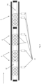
figure 1 shows a first embodiment of a prior art apparatus for filling and capping bottles; -
figure 2 shows a second embodiment of a prior art apparatus for filling and capping bottles; -
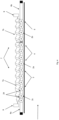
figure 3 shows a side view of a first embodiment of an apparatus of the present invention; -
figure 4 shows a detail offigure 3 , wherein the bottles shown have a cylindrical shape and wherein the contact area between the cochlea and each single bottle being pushed is shown; -
figure 5 shows a detail similar tofigure 4 , wherein the contact area between the cochlea and each individual bottle in slowing movement is shown; -
figure 6 shows a sectional detail of a bottle offigure 4 , wherein the anticipating and delaying cochlea phase and the bottles lateral guides are schematically shown; -
figure 7 shows a bottle of smaller dimensions than the one shown infigure 6 ; -
figure 8 shows a sectional detail of the automatic control of the bottle lateral guides; -
figure 9 shows a detail similar tofigure 4 , wherein the bottles shown have a square rather than cylindrical shape. - With reference to
figures 3 to 9 , an embodiment of an apparatus 1 of the present invention for the continuous filling and capping cycle of a plurality ofcontainers 2, in particular of bottles to be filled with water, is shown. - As shown in
figure 3 and in detail infigure 4 , the apparatus 1 of the present invention includes a rinsing section 3 (optional), afilling section 4 and acapping section 5 of thebottles 2, arranged in this order along the travel direction of thefirst section 6a and of thesecond section 6b of the conveyor belt 6, aligned with each other, so that a first group of stillempty bottles 2a is brought via thefirst section 6a of the conveyor belt 6 to thesection filling section 4 and, at the same time, a second group of filledbottles 2b is carried via thesecond section 6b of the conveyor belt 6 from the fillingsection 4 to thecapping section 5. In the optional case wherein therinsing section 3 is also present (as shown in the figures), thefirst section 6a of the conveyor belt 6 also leads a third group ofbottles 2c to therinsing section 3, and then in turn allowing them to pass in subsequent phases first to thefilling section 4 and then to thecapping section 5. - The
rinsing section 3 is provided with a plurality of grippers/nozzles 12 (four grippers/nozzles 12 are shown infigure 3 , but the number of grippers/nozzles 12 could be greater or lesser depending on the production request), arranged in line along the travel direction of thefirst section 6a of the conveyor belt 6, and designed to facilitate the bottle rinsing. - The filling
section 4 is provided with a plurality of filling valves 10 (four fillingvalves 10 are shown infigure 3 , but the number of fillingvalves 10 could be greater or less depending on the hourly production request of the filling line), arranged in line along the travel direction of thefirst section 6a of the conveyor belt 6. The number of fillingvalves 10 in thefilling section 4 is equal to the number of grippers/nozzles 12 in therinsing section 3 so that, operationally, while a certain number ofbottles 2c positioned in therinsing section 3 are washed, at the same time the same number of another group of rinsed andempty bottles 2a is subjected to filling in thefilling section 4. In another embodiment the number of fillingvalves 10 in thefilling section 4 can be greater or less than the number of clamps/nozzles 12 in therinsing section 3. - The
capping section 5 consists of a capping device equipped with a cappinghead 11, particularly suitable for hourly productions of up to approximately 1000-1100bottles 2 per hour. In alternative embodiments it is possible to envisage the use of two cappingheads 11 for productions of up to 2000-2200bottles 2 per hour, or even three or more capping heads 11 for higher productions. - The apparatus 1 also includes a
cochlea 7, which includes afirst cochlea section 7a, extending in correspondence with thefirst conveyor belt 6a, from therinsing section 3 to the filling section 4 (or, in the absence of therinsing section 3, directly from the inlet section of the machine to the filling section 4), and asecond cochlea section 7b, extending in correspondence with thesecond conveyor belt 6b, from the end of thefilling section 4 to thecapping section 5. - The apparatus 1 also includes
first motorization elements 8 suitable for activating thefirst cochlea section 7a andsecond motorization elements 9 suitable for activating thesecond cochlea section 7b. Thefirst motorization elements 8 are independent of thesecond motorization elements 9. - It is important that the
first cochlea section 7a and thesecond cochlea section 7b are operated in synchronism with each other, maintaining the containers at a machine pitch, during the simultaneous phases wherein eachbottle 2a of the first group of still empty bottles is transported in correspondence with the fillingsection 4 and wherein eachbottle 2b of the second group of filled bottles is transported from the fillingsection 4 to thecapping section 5, maintaining the machine pitch up to thecapping section 5 itself. - It is also relevant that the
first cochlea section 7a is able to remain stationary while waiting for the filling of the first group ofempty bottles 2a in thefilling section 4 to be completed. - The
second cochlea section 7b is designed to alternate a) rotating phases, during which each filledbottle 2b is advanced in thecapping section 5 until abottle 2b arrives individually at the cappinghead 11, and b) stopping phases, to give thecapping head 11 time to cap the filledbottle 2b. - The total cycle time of the capping phase of all the
bottles 2b (previously filled in thefilling section 4 and brought in succession to thesingle capping head 11 in the capping section 5) is preferably not greater than the cycle time necessary for filling all theempty bottles 2a of the new group of bottles brought to the series of fillingvalves 10 in thefilling section 4. - In this way, while all the
bottles 2a of the first group have been filled in thefilling section 4, thebottles 2b of the second group have already been capped in thecapping section 5 and sent to an area where other machines are positioned, typically for labelling and/or packaging. Consequently, thesecond cochlea section 7b is left empty and ready to receive the new filledbottles 2a of the first group. - Once the capping phase is completed, the
second cochlea section 7b realigns and brings itself back in phase with thefirst cochlea section 7a, waiting for the filling cycle to be completed, upon its completion the twocochlea sections empty bottles 2c enter the rinsing section (if present) to be rinsed, the already rinsedbottles 2a are transferred to thefilling section 4 to be filled, and the filledbottles 2b are transferred to thesecond cochlea section 7b, always at the machine pitch, waiting for the capping phase to begin. - Once the transfer phase between the various sections of the machine is completed, the rinsing (if present) and filling cycles are repeated, with the
first cochlea section 7a stopped, and the capping cycle is repeated too, with thesecond cochlea section 7b alternating rotating phases and stopping phases to allow thebottles 2b to be individually capped. - The
first motorization elements 8 and/or thesecond motorization elements 9 are chosen from the group that includes gearboxes, brushless motors, stepper motors, asynchronous motors with current inverter, or other types of motorizations suitable for moving thefirst cochlea section 7a and thesecond cochlea section 7b with different motion laws. - All the
bottles 2 shown infigure 4 have a cylindrical shape and all of them have the same diameter. - However, the apparatus 1 of the present invention is also suitable for
processing bottles 2 having different diameters and also having shapes that are not only cylindrical but also, for example, square or rectangular, such as to include almost all of the bottle formats usually used on the market. For example,figure 9 shows the presence of square-shapedbottles 2d. - In fact, in order not to be affected by the difference in diameters and shapes of the
bottles 2 used, in one embodiment thefirst motorization elements 8 and/or thesecond motorization elements 9 of the apparatus 1 of the present invention are suitable for anticipating the phase of thefirst cochlea section 7a and/or of thesecond cochlea section 7b by means of an adequate rotation of theinvolved cochlea section cochlea section contact area 25 between eachcochlea section 7 and eachsingle bottle 2 in slowing down movement infigure 5 ; this anticipating phase by rotating thecochlea 7 is also shown by thearrow 26 in an anti-clockwise direction infigures 6 and 7 ). - Similarly, in another embodiment the
first motorization elements 8 and/or thesecond motorization elements 9 of the apparatus 1 of the present invention are suitable for delaying the phase of thefirst cochlea section 7a and/or of thesecond cochlea section 7b by means of an adequate rotation in the opposite direction compared to the case seen above, therefore with an axial movement of the two cochlea in the travel direction of theinvolved cochlea section contact area 24 between eachcochlea section 7 and eachsingle bottle 2 being pushed infigure 4 ; this timing delay by rotating thecochlea 7 is also shown by theclockwise arrow 27 infigures 6 and 7 ). - Thanks to this rotation of the
cochlea 7, by acting on thebottles 2 in the pushing direction or in the slowing down opposite direction, a notable difference in diameter can be recovered, without changing thecochlea 7. In this way thebottles 2 are allowed to position themselves at a machine pitch and always be aligned with the fillingvalves 10 in thefilling section 4, aligned with the cappinghead 11 in thecapping section 5 and aligned with the clamps/nozzles 12 of the rinsing section 3 (if the latter is present). - Furthermore, to laterally compensate for any difference in diameter of the
bottles 2 shown infigures 6 and 7 (where the bottle 2' has a diameter dl and thebottle 2" has a diameter d2, smaller than d1), the apparatus 1 of the present invention is provided with one ormore guides 13 placed on one or both sides of thebottles 2' and 2", depending on their size and shape, for theentire cochlea 7 length. The twobottles 2' and 2" of different diameters are both moved on the samelongitudinal axis 28, which preferably coincides with the axis of thefirst section 6a and/or thesecond section 6b of the conveyor belt 6. Theinternal diameter 14 of thecochlea 7, called "core", is located at a different distance from the twobottles 2' and 2" which, however, by means of the lateral guides 13, are kept on thesame axis 28, which preferably coincides with that of thefirst section 6a and/or thesecond section 6b of the conveyor belt 6, and therefore also in axis with the elements (grippers/nozzles 12, fillingvalves 10, capping head 11) present respectively in the rinsing 3 section (if provided), filling 4 section and capping 5 sections. - Thanks to the lateral guides 13 and also taking advantage of the seen above phase adjustment (anticipating/delaying) of the
cochlea 7, it is also possible to process non-cylindrical bottles 2 (such as, for example, the square-shapedbottles 2d shown infigure 9 ), without any format change related to the bottle dimensions. - The
guides 13 are manually adjusted with quick intervention by the operator, without having to change any components; the adjustment of theguides 13 can also be automatic, via pneumatic orelectric systems 15 or similar (schematized infigure 8 ), to completely automate the format change relating to the shape and dimensions of thebottles 2. - Of course, many modifications and variations of the preferred embodiments described will be apparent to those skilled in the art, while still remaining within the scope of the invention.
- For example, in the previous description and in the figures of the present invention an embodiment is shown wherein a
rinsing section 3 is always present. However, other embodiments of the present invention could be devoid of this rinsing section, although falling within the scope of protection of the invention itself. - An alternative embodiment (not shown in the figures) can provide a variant with
cochlea 7 in three distinct sections, rinsingsection 3, fillingsection 4 andcapping section 5, to separate the three distinct phases of the machine and/or with three independent motors or can provide an accumulation ofbottles 2 before the capping device, if necessary, while maintaining the same advantages described above of having one or more parts of thecochlea 7 which can be managed with different motion laws, which involve movement phases alternated with resting phases not necessarily in phase with each other. - Yet a further variant (not shown in the figures) could consist of a machine which has the
capping section 5 not in axis with the first two rinsingsections 3 and fillingsections 4, wherein the movement of the filledbottles 2b occurs via pushing devices on a second section of conveyor belt parallel to the first section of conveyor belt or in any case with thecapping section 5 separate from therinsing section 3 and fillingsection 4. - Yet a further variant (not shown in the figures) could provide a further cochlea opposite the
cochlea 7, at least in the filling and capping section, to move the bottles with two opposing cochleae, i.e., positioned on opposite sides of the bottles; this further cochlea will be made up of two or more sections, exactly as thecochlea 7. - Yet a further variant (not shown in the figures) could involve replacing the
cochlea 7 with similar systems such as, for example, chains and/or belts with spacer elements fixed at machine pitch which perform the same function as thecochlea 7, or of the two parts ofcochlea - Therefore, the present invention is not limited to the preferred embodiments described, illustrated for illustrative and non-limiting purposes only, but is defined by the following claims.
Claims (9)
- Apparatus (1) for the continuous filling and capping cycles of a plurality of containers (2), wherein said apparatus (1) comprises at least one filling section (4) for filling of each of said containers (2) with a liquid or solid, at least one capping section (5) for capping each of said containers (2) once they are filled, wherein said filling section (4) is provided with at least one filling element (10) and wherein said filling section capping (5) is equipped with a capping device with at least one capping head (11),
characterized in that said apparatus (1) also comprises:- at least a first conveyor belt section (6a) adapted to transport a first still empty group (2a) of said plurality of containers (2) in correspondence with said at least one filling section (4) and a second conveyor belt section (6b) adapted to transport to said at least one capping section (5) a second group (2b) of said plurality of containers (2) filled in said at least one filling section (4),- a cochlea device (7), comprising a first cochlea section (7a) extending in correspondence with said first conveyor belt section (6a) in said at least one filling section (4) and a second cochlea section (7b) extending in correspondence with said second conveyor belt section (6b) between the end of said filling section (4) and said capping section (5),- first motorization elements (8) suitable for activating said first cochlea section (7a) and second motorization elements (9) suitable for activating said second cochlea section (7b), wherein said first motorization elements (8) are independent from said second motorization elements (9),and wherein:- said first cochlea section (7a) and said second cochlea section (7b) are operated in synchronism with each other, maintaining the containers at a machine pitch, during the simultaneous phases wherein each still empty container (2a) of said first group of containers (2) is transported in correspondence with said at least one filling section (4) and wherein each filled container (2b) of said second group of containers (2) is transported from said filling section (4) to said filling section capping (5),- said first cochlea section (7a) is adapted to remain stationary while waiting the filling of said first group of empty containers (2a) in said filling section (4) is completed, and- said second cochlea section (7b) is adapted to alternate a) rotating phases, during which each of said filled containers (2b) is advanced to the capping section (5) until it is individually positioned in correspondence with said capping head (11), and b) stopping phases, for the time necessary to align the single filled container (2b) in axis with said capping head (11) and to cap the filled container (2b),- wherein said first motorization elements (8) and/or said second motorization elements (9) are suitable for anticipating/delaying the first cochlea section (7a) phase and/or the second cochlea section (7b) phase by angular rotating the involved cochlea section (7a,7b), so that the propeller of that cochlea section (7a,7b) is axially moved in the opposite direction to that one of the containers (2), in the case of phase anticipating or, respectively, in the travel direction of the containers (2), in the case of delaying phase, to allow said containers (2) to remain at the machine pitch and in axis with said filling elements (10) in the filling section (4) and in axis with said at least one capping head (11) in the capping section (5) even if said containers (2) have different diameters and/or shapes from each other. - Apparatus (1) according to claim 1, wherein said first conveyor belt section (6a) and said second conveyor belt section (6b) are aligned with each other.
- Apparatus (1) according to any of the previous claims wherein said filling section (4) is provided with a plurality of filling valves (10) arranged in line along the travel direction of the first conveyor belt section (6a).
- Apparatus (1) according to any of the previous claims which further comprises at least one rinsing section (3) for rinsing of each of said containers (2a) placed before said at least one filling section (4) along the travel direction of said first conveyor belt section (6a).
- Apparatus (1) according to claim 4, wherein said first cochlea section (7a) extends both in said at least one rinsing section (3) and in said at least one filling section (4), and wherein said first cochlea section (7a) is operated in synchronism with said second cochlea section (7b), maintaining the containers at machine pitch, even during each of said containers (2a) moving from said rinsing section (3) to said filling section (4).
- Apparatus (1) according to any of the previous claims, wherein said containers (2) are bottles and wherein said liquid is water, or other drinkable liquid or for industrial use, or wherein said solid is constituted for example by pieces of fruit.
- Apparatus (1) according to any one of the previous claims, wherein said first motorization elements (8) and/or said second motorization elements (9) are selected from the group including gearboxes, Brushless motors, stepper motors, asynchronous motors with current inverter, or other types of motors suitable for moving said first cochlea section (7a) and said second cochlea section (7b) with different motion laws.
- Apparatus (1) according to any of the previous claims 3-7, wherein said first motorization elements (8) and/or said second motorization elements (9) are suitable to allow the bottles (2) to be positioned at the machine pitch and to always be in axis with said filling valves (10) in the filling section (4) and in axis with said capping head (11) in the capping section (5).
- Method for filling and capping a plurality of containers (2) using the apparatus (1) according to any of the preceding claims 1-8, wherein the method comprises the steps of:a) operating the first cochlea section (7a), extending along the first conveyor belt section (6a) in the rinsing section (3) and in the filling section (4), so that a first group of empty containers (2c) coming from transport or supply means upstream of the apparatus (1), reaches the rinsing section (3) and a second group of rinsed containers (2a) reaches the filling section (4); at the same time activating the second cochlea section (7b), extending along the second conveyor belt section (6b) between the end of the filling section (4) and the capping section (5), and positioning in this section the filled containers (2b) coming from the filling section (4);b) stopping the first cochlea section (7a), so that each empty container (2a) of the first group of containers is in correspondence with the axis of the clamps/nozzles (12) of the rinsing section (3) and each rinsed container from the rinsing section (3) is located in correspondence with the filling elements (10) in the filling section (4),c) starting the container rinsing phase and the container filling phase;d) activating the second cochlea section (7b), so that the filled containers (2b) are first individually transferred with an alternating motion to the capping device (11) and, subsequently, once capped, they are transferred from the capping section (5) onto special transport means to be, if necessary, transferred to packaging machines present in the bottling lines;e) repeating the previous steps for the number of times necessary to fill and cap the required quantities of containers (2),
wherein:- the first and second cochlea sections (7a,7b) are operated in synchronism with each other, keeping the containers at machine pitch, respectively, by first and second motorization elements (8,9), independent of each other,- the second cochlea section (7b) is designed to alternate a) rotating phases, during which each of the filled containers (2b) is advanced in the capping section (5) until it is individually positioned in correspondence with the capping head (11), and b) stopping phases, for the time necessary to align the single filled container (2b) in axis with the capping head (11) and to cap the filled container (2b),- wherein said first motorization elements (8) and/or said second motorization elements (9) are suitable for anticipating/delaying the first cochlea section (7a) phase and/or of the second cochlea section (7b) phase by rotating the affected cochlea section (7a,7b), so that the propeller of that cochlea section (7a,7b) is axially moved, in the opposite direction to that one of the containers (2), in the case of anticipating phase, or, respectively, in the travel direction of the containers (2), in the case of delaying phase, to allow said containers (2) to remain at the machine pitch and in axis with said filling elements (10) in the filling section (4) and in axis with said at least one capping head (11) in the capping section (5) even if said containers (2) have different diameters and/or shapes from each other.
Applications Claiming Priority (1)
| Application Number | Priority Date | Filing Date | Title |
|---|---|---|---|
| IT102022000018285A IT202200018285A1 (en) | 2022-09-08 | 2022-09-08 | Apparatus for filling and capping containers for liquids and related method |
Publications (1)
| Publication Number | Publication Date |
|---|---|
| EP4353673A1 true EP4353673A1 (en) | 2024-04-17 |
Family
ID=84360097
Family Applications (1)
| Application Number | Title | Priority Date | Filing Date |
|---|---|---|---|
| EP23020415.8A Pending EP4353673A1 (en) | 2022-09-08 | 2023-09-01 | Apparatus for filling and capping liquid containers and related method without format change |
Country Status (2)
| Country | Link |
|---|---|
| EP (1) | EP4353673A1 (en) |
| IT (1) | IT202200018285A1 (en) |
Citations (2)
| Publication number | Priority date | Publication date | Assignee | Title |
|---|---|---|---|---|
| WO2020025411A1 (en) | 2018-08-01 | 2020-02-06 | Lindauer Dornier Gesellschaft Mit Beschränkter Haftung | Device for adjusting the warp tension of warp threads |
| WO2020254111A1 (en) | 2019-06-17 | 2020-12-24 | Quinti S.R.L. | Machine, particularly of the type with increased productivity |
-
2022
- 2022-09-08 IT IT102022000018285A patent/IT202200018285A1/en unknown
-
2023
- 2023-09-01 EP EP23020415.8A patent/EP4353673A1/en active Pending
Patent Citations (2)
| Publication number | Priority date | Publication date | Assignee | Title |
|---|---|---|---|---|
| WO2020025411A1 (en) | 2018-08-01 | 2020-02-06 | Lindauer Dornier Gesellschaft Mit Beschränkter Haftung | Device for adjusting the warp tension of warp threads |
| WO2020254111A1 (en) | 2019-06-17 | 2020-12-24 | Quinti S.R.L. | Machine, particularly of the type with increased productivity |
Also Published As
| Publication number | Publication date |
|---|---|
| IT202200018285A1 (en) | 2024-03-08 |
Similar Documents
| Publication | Publication Date | Title |
|---|---|---|
| US8474603B2 (en) | Transport system for moving a plurality of containers through a plurality of work stations | |
| US4901504A (en) | Filling and casing system | |
| US7481309B2 (en) | Method of separating, synchronizing and compacting packed groups of articles | |
| US10766650B2 (en) | Controlled feed for batch packaging | |
| EP3094590B1 (en) | Container-processing machine for processing containers | |
| US7543424B2 (en) | Beverage bottling plant for filling and closing beverage bottles with a packaging device for packaging beverage bottles | |
| US8935903B2 (en) | Centering unit for aligning at least two grouped vessels and method for aligning two grouped vessels | |
| US5425402A (en) | Bottling system with mass filling and capping arrays | |
| US2829757A (en) | Container feeding mechanisms | |
| US7779874B2 (en) | Method of filling kegs with a liquid beverage in a keg filling plant | |
| US20180141688A1 (en) | Batch packaging architecture with controlled feed | |
| EP1864942A1 (en) | Container transportation line for bottling plants | |
| US5158168A (en) | Container transfer device | |
| EP4353673A1 (en) | Apparatus for filling and capping liquid containers and related method without format change | |
| US20180170590A1 (en) | Product packaging apparatus | |
| US8701375B2 (en) | Container treatment plant and method of treating containers | |
| JP7582975B2 (en) | Conveying method and system, in particular for a machine for filling bottles in the pharmaceutical industry | |
| EP0798263A1 (en) | Container capping and filling apparatus | |
| CA2539241A1 (en) | A bottling plant for filling bottles with a liquid filling material having a container cleaning machine with a conveyor for conveying bottles with driven conveyor elements | |
| JP7758922B2 (en) | Container Processing System | |
| EP3983330B1 (en) | Machine with a bottle assembly | |
| US3212227A (en) | Case loader and method of loading cases | |
| CN1308582A (en) | Pipe Processing Line | |
| EP3476796A1 (en) | A method and cap feeding device for applying caps to a neck of a container | |
| US20250026062A1 (en) | Coupling of production machine and stretch blow molding machine via air transport |
Legal Events
| Date | Code | Title | Description |
|---|---|---|---|
| PUAI | Public reference made under article 153(3) epc to a published international application that has entered the european phase |
Free format text: ORIGINAL CODE: 0009012 |
|
| STAA | Information on the status of an ep patent application or granted ep patent |
Free format text: STATUS: THE APPLICATION HAS BEEN PUBLISHED |
|
| AK | Designated contracting states |
Kind code of ref document: A1 Designated state(s): AL AT BE BG CH CY CZ DE DK EE ES FI FR GB GR HR HU IE IS IT LI LT LU LV MC ME MK MT NL NO PL PT RO RS SE SI SK SM TR |
|
| STAA | Information on the status of an ep patent application or granted ep patent |
Free format text: STATUS: REQUEST FOR EXAMINATION WAS MADE |
|
| 17P | Request for examination filed |
Effective date: 20241015 |
|
| RBV | Designated contracting states (corrected) |
Designated state(s): AL AT BE BG CH CY CZ DE DK EE ES FI FR GB GR HR HU IE IS IT LI LT LU LV MC ME MK MT NL NO PL PT RO RS SE SI SK SM TR |