EP4353531A1 - Vehicular seat assembly having expandable seat back section - Google Patents
Vehicular seat assembly having expandable seat back section Download PDFInfo
- Publication number
- EP4353531A1 EP4353531A1 EP23202823.3A EP23202823A EP4353531A1 EP 4353531 A1 EP4353531 A1 EP 4353531A1 EP 23202823 A EP23202823 A EP 23202823A EP 4353531 A1 EP4353531 A1 EP 4353531A1
- Authority
- EP
- European Patent Office
- Prior art keywords
- seat
- attachment means
- detachable attachment
- support beam
- seat back
- Prior art date
- Legal status (The legal status is an assumption and is not a legal conclusion. Google has not performed a legal analysis and makes no representation as to the accuracy of the status listed.)
- Granted
Links
Images






Classifications
-
- B—PERFORMING OPERATIONS; TRANSPORTING
- B64—AIRCRAFT; AVIATION; COSMONAUTICS
- B64D—EQUIPMENT FOR FITTING IN OR TO AIRCRAFT; FLIGHT SUITS; PARACHUTES; ARRANGEMENT OR MOUNTING OF POWER PLANTS OR PROPULSION TRANSMISSIONS IN AIRCRAFT
- B64D11/00—Passenger or crew accommodation; Flight-deck installations not otherwise provided for
- B64D11/06—Arrangements of seats, or adaptations or details specially adapted for aircraft seats
- B64D11/0647—Seats characterised by special upholstery or cushioning features
-
- B—PERFORMING OPERATIONS; TRANSPORTING
- B60—VEHICLES IN GENERAL
- B60N—SEATS SPECIALLY ADAPTED FOR VEHICLES; VEHICLE PASSENGER ACCOMMODATION NOT OTHERWISE PROVIDED FOR
- B60N2/00—Seats specially adapted for vehicles; Arrangement or mounting of seats in vehicles
- B60N2/24—Seats specially adapted for vehicles; Arrangement or mounting of seats in vehicles for particular purposes or particular vehicles
- B60N2/30—Non-dismountable or dismountable seats storable in a non-use position, e.g. foldable spare seats
- B60N2/3038—Cushion movements
- B60N2/304—Cushion movements by rotation only
- B60N2/3045—Cushion movements by rotation only about transversal axis
- B60N2/3047—Cushion movements by rotation only about transversal axis the cushion being hinged at the back-rest
-
- B—PERFORMING OPERATIONS; TRANSPORTING
- B64—AIRCRAFT; AVIATION; COSMONAUTICS
- B64D—EQUIPMENT FOR FITTING IN OR TO AIRCRAFT; FLIGHT SUITS; PARACHUTES; ARRANGEMENT OR MOUNTING OF POWER PLANTS OR PROPULSION TRANSMISSIONS IN AIRCRAFT
- B64D11/00—Passenger or crew accommodation; Flight-deck installations not otherwise provided for
- B64D11/06—Arrangements of seats, or adaptations or details specially adapted for aircraft seats
- B64D11/0639—Arrangements of seats, or adaptations or details specially adapted for aircraft seats with features for adjustment or converting of seats
- B64D11/064—Adjustable inclination or position of seats
-
- B—PERFORMING OPERATIONS; TRANSPORTING
- B64—AIRCRAFT; AVIATION; COSMONAUTICS
- B64D—EQUIPMENT FOR FITTING IN OR TO AIRCRAFT; FLIGHT SUITS; PARACHUTES; ARRANGEMENT OR MOUNTING OF POWER PLANTS OR PROPULSION TRANSMISSIONS IN AIRCRAFT
- B64D11/00—Passenger or crew accommodation; Flight-deck installations not otherwise provided for
- B64D11/06—Arrangements of seats, or adaptations or details specially adapted for aircraft seats
- B64D11/0698—Seats suspended from aircraft walls
Definitions
- Conventional troop seating covers include a one-piece fabric cover with a straight back positioned at an angle to the seat bottom, which can cause an occupant to be pushed forward away from full contact with the seat back when the occupant is wearing an equipment pack. This reduction in body support can degrade comfort and safety for the occupant.
- inventions of the inventive concepts disclosed herein are directed to a system.
- the system may include a vehicular seat assembly.
- the vehicular seat assembly may include a first seat support beam, a second seat support beam, a fold-out seat pan, a bar, a fabric seat back, and at least one detachable attachment means.
- the fold-out seat pan may be configured to fold out to a seat pan deployed state.
- the fold-out seat pan may be rotatably coupled to first seat support beam and the second seat support beam.
- the bar may be positioned between the first seat support beam and the second seat support beam.
- the fabric seat back may have a first end and a second end. The fabric seat back may be secured at the first end to the bar.
- the fabric seat back may extend from the first end toward the second end.
- the fabric seat back may have an expandable seat back section.
- the expandable seat back section may be secured at the second end to the fold-out seat pan.
- Each of the at least one detachable attachment means may be secured at a first detachable attachment means end to the fold-out seat pan.
- Each of the at least one detachable attachment means may be secured at a second detachable attachment means end to a portion of the fabric seat back located between the first end and the second detachable attachment means end.
- the expandable seat back section may extend from the second end at least to the second releasable attachment means end.
- Each of the at least one detachable attachment means may be configured to be in an attached state or a detached state. When all of the detachable attachment means are in the detached state an effective length of the fabric seat back may extend to include the expandable seat back section.
- inventive concepts are not limited in their application to the details of construction and the arrangement of the components or steps or methodologies set forth in the following description or illustrated in the drawings.
- inventive concepts disclosed herein may be practiced without these specific details.
- well-known features may not be described in detail to avoid unnecessarily complicating the instant disclosure.
- inventive concepts disclosed herein are capable of other embodiments or of being practiced or carried out in various ways. Also, it is to be understood that the phraseology and terminology employed herein is for the purpose of description and should not be regarded as limiting.
- a letter following a reference numeral is intended to reference an embodiment of the feature or element that may be similar, but not necessarily identical, to a previously described element or feature bearing the same reference numeral (e.g., 1, 1a, 1b).
- reference numeral e.g. 1, 1a, 1b
- Such shorthand notations are used for purposes of convenience only, and should not be construed to limit the inventive concepts disclosed herein in any way unless expressly stated to the contrary.
- any reference to "one embodiment,” or “some embodiments” means that a particular element, feature, structure, or characteristic described in connection with the embodiment is included in at least one embodiment of the inventive concepts disclosed herein.
- the appearances of the phrase “in some embodiments” in various places in the specification are not necessarily all referring to the same embodiment, and embodiments of the inventive concepts disclosed may include one or more of the features expressly described or inherently present herein, or any combination of sub-combination of two or more such features, along with any other features which may not necessarily be expressly described or inherently present in the instant disclosure.
- the seat assembly may include: a fabric seat back having an expandable seat back section; and at least one detachable attachment means configured to be in an attached state or a detached state, wherein when all of the at least one detachable attachment means are in the detached state, an effective length of the fabric seat back extends to include the expandable seat back section.
- Some embodiments may include a fabric seat back having a two-state configuration that can be quickly and easily switched to an attached state (e.g., a no-pack state) and a detached state (e.g., a pack-equipped state), which may carry occupant loading during flight and crash situations.
- Some embodiments may improve occupant comfort and safety by allowing both an unequipped or a pack-equipped occupant to nest fully back into the fabric seat back for comfort and effective load transfer.
- FIGS. 1-2 an exemplary embodiment of a system 100 including a vehicle (e.g., aircraft (e.g., rotorcraft 102), watercraft, automobile, train, etc.) including at least one seat assembly (e.g., a vehicular seat assembly (e.g., an aircraft seat assembly (e.g., a rotorcraft seat assembly 104))) is depicted according to the inventive concepts.
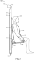
- FIGS. 1-2 show an occupant 200 seated without a pack (e.g., 202, such as shown in FIGS. 3-5 ).
- a pack e.g., 202, such as shown in FIGS. 3-5
- one, some, or all of the at least one detachable attachment means e.g., 126, such as shown in FIGS. 3-8 ) may be in an attached state.
- each seat assembly may have at least one seat support beam 106 (e.g., two seat support beams 106 as shown), at least one fold-out seat pan 108, a bar 110, a fabric seat back 112, an expandable seat back section 114, at least one top attachment structure 116 (e.g., at least one top attachment bracket), at least one bottom attachment structure 118 (e.g., at least one bottom attachment pin), a harness 120, at least one hinge 122, at least one hinge bracket 124, and/or at least one fabric seat side 132, some or all of which may be coupled to another at any given time.
- a seat support beam 106 e.g., two seat support beams 106 as shown
- at least one fold-out seat pan 108 e.g., a bar 110
- a fabric seat back 112 an expandable seat back section 114
- at least one top attachment structure 116 e.g., at least one top attachment bracket
- at least one bottom attachment structure 118 e.g., at least one
- the seat assembly (e.g., a vehicular seat assembly (e.g., an aircraft seat assembly (e.g., a rotorcraft seat assembly 104)) may be installed within the vehicle (e.g., aircraft (e.g., rotorcraft 102), watercraft, automobile, train, etc.), such as via the at least one top attachment structure 116 (e.g., the at least one top attachment bracket) and the at least one bottom attachment structure 118 (e.g., the at least one bottom attachment pin) being attached to interior attachment points of the vehicle.
- the vehicle e.g., aircraft (e.g., rotorcraft 102), watercraft, automobile, train, etc.
- the at least one top attachment structure 116 e.g., the at least one top attachment bracket
- the at least one bottom attachment structure 118 e.g., the at least one bottom attachment pin
- FIGS. 3-5 an exemplary embodiment of the system 100 of FIGS. 1-2 is depicted according to the inventive concepts.
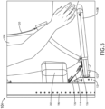
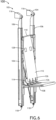
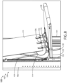
- FIGS. 3-5 show an occupant 200 seated with a pack 202.
- all of the at least one detachable attachment means 126 may be in a detached state.
- the second seat support beam 106 may be parallel to the first seat support beam.
- the first seat support beam 106 may be a first vertical seat support beam
- the second seat support beam 106 may be a second vertical seat support beam.
- each of the first and second seat support beam 106 may be telescoping beams.
- the fold-out seat pan 108 may be configured to fold out to a seat pan deployed state (as shown).
- the fold-out seat pan may be rotatably coupled to first seat support beam 106 and the second seat support beam 106 via the hinges 122 and corresponding hinge brackets 124 such that the fold-out seat can move from the deployed state to a folded up stowed state (not shown).
- the fold-out seat pan 108 may be composed at least of nylon (e.g., military grade nylon).
- the bar 110 may be positioned between the first seat support beam 106 and the second seat support beam 106. In some embodiments, the bar 110 may be a horizontal bar. In some embodiments, the bar 110 may be coupled to the first seat support beam 106 and to the second seat support beam 106.
- the fabric seat back 112 may have a first end and a second end, the fabric seat back 112 secured (e.g., wrapped around and sewn, or attached via rings) at the first end to the bar 110.
- the fabric seat back 112 may extend from the first end toward the second end.
- the fabric seat back 112 may have an expandable seat back section 114.
- the expandable seat back section may be secured at the second end to the fold-out seat pan 108.
- the fabric seat back 112 may be composed at least of nylon (e.g., military grade nylon).
- Each of the at least one detachable attachment means 126 may be secured at a first detachable attachment means end 126 to the fold-out seat pan 108.
- the expandable seat back section 114 may extend from the second end at least to the second detachable attachment means end (e.g., of the strap 126C, as shown in FIGS. 15-16 ). In some embodiments, the expandable seat back section 114 may have a length of five to ten inches. In some embodiments, the expandable seat back section 114 may extend from the second end past the second detachable attachment means end (e.g., of the strap 126C, as shown in FIGS. 15-16 ).
- Each of the at least one detachable attachment means 126 may be configured to be in an attached state or a detached state.
- an effective length e.g., a usable length (e.g., by the occupant 200) of the fabric seat back 112) of the fabric seat back 112 may extend to include the expandable seat back section 114.
- an occupant 200 wearing a pack 202 may sit in the seat assembly such that the pack 202 may be positioned against the fabric seat back 112 while the fold-out seat pan 108 and the fabric seat back 112 support (e.g., fully, safely, and/or comfortably support) the occupant 200 wearing the pack 202.
- FIGS. 6-8 an exemplary embodiment of the system 100 of FIGS. 1-5 is depicted according to the inventive concepts. As shown in FIGS. 6-8 , all of the at least one detachable attachment means 126 may be in an attached state.
- the fabric seat back 112 may include one or more harness apertures 128 configured to accommodate the harness 120 passing through the fabric seat back 112.
- the seat assembly may include angled support rods 130.
- Each of the angled support rods 130 may be coupled to the first seat support beam 106 and the second seat support beam 106.
- the angled support rods 130 may act as truss supports between the first seat support beam 106 and the second seat support beam 106.
- FIGS. 9-12 an exemplary embodiment of the system 100 of FIGS. 1-8 is depicted according to the inventive concepts.
- FIGS. 9-12 show a pack 202 positioned against the fabric seat back 112. As shown in FIGS. 9-12 , all of the at least one detachable attachment means 126 may be in a detached state.
- each of the at least one detachable attachment means 126 may comprise a first detachable attachment means portion 126A and a second detachable attachment means portion 126B.
- each detachable attachment means 126 e.g., three detachable means 126, as shown
- each detachable attachment means 126 may comprise a buckle having a female buckle portion (e.g., 126A) and a male buckle portion (e.g., 126B).
- each of the detachable attachment means 126 may comprise any suitable detachable attachment means, such as a clip and ring, hook and ring, button, a snap, or the like.
- each of the at least one detachable attachment means 126 may be composed at least of a metal material (e.g., aluminum, steel, or the like). In some embodiments, each of the at least one detachable attachment means 126 may be configured to support a tensile force of at least 5,000 Newtons (e.g., such as 9,000 Newtons or more).
- FIGS. 13-15 an exemplary embodiment of the system 100 of FIGS. 1-12 is depicted according to the inventive concepts.
- FIGS. 13-15 show a portion of a seat assembly. As shown in FIGS. 13-15 , all of the at least one detachable attachment means 126 may be in a detached state.
- each of the at least one detachable attachment means 126 may comprise a first detachable attachment means portion 126A, a second detachable attachment means portion 126B, a first strap 126C, and a second strap 126D.
- each detachable attachment means 126 may comprise a buckle having a female buckle portion (e.g., 126A), a male buckle portion (e.g., 126B), a first strap 126C coupled to the fabric seat back 112 and the first buckle portion (e.g., 126A), and a second strap 126D coupled to the fold-out seat pan 108 and/or the fabric seat back 112 and to the male buckle portion (e.g., 126B).
- each of the detachable attachment means 126 may comprise any suitable detachable attachment means, such as a clip and ring, hook and ring, button, a snap, or the like.
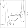
- FIG. 16 an exemplary embodiment of the system 100 of FIGS. 1-15 is depicted according to the inventive concepts.
- FIGS. 16 show a portion of the seat assembly.
- FIG. 16 shows a transition from all of the at least one detachable attachment means 126 being in an attached state to being in a detached state.
- the fabric seat back 112 when all of the detachable attachment means 126 are in the detached state, the fabric seat back 112 may be configured to move toward a position denoted by positions 112A (e.g., indicative of a position of the fabric seat back 112) and 114A (e.g., indicative of a position of the expandable seat back section 114 of the fabric seat back 112).
- the fabric seat back 112 may move at least in part toward the first seat support beam 106 and toward the second seat support beam 106 when all of the detachable attachment means 126 are in the detached state.
- an occupant 200 and their pack 202 may push back against the fabric seat back 112 to allow the expandable seat back section 114 to fully extend along the occupant 200 and the pack 202 interface to fully support and carry loading.
- embodiments of the inventive concepts disclosed herein may be directed to a system including a seat assembly.
- At least one means one or a plurality of; for example, “at least one” may comprise one, two, three, ..., one hundred, or more.
- one or more means one or a plurality of; for example, “one or more” may comprise one, two, three, ..., one hundred, or more.
- zero or more means zero, one, or a plurality of; for example, “zero or more” may comprise zero, one, two, three, ..., one hundred, or more.
- the methods, operations, and/or functionality disclosed may be implemented as sets of instructions or software readable by a device. Further, it is understood that the specific order or hierarchy of steps in the methods, operations, and/or functionality disclosed are examples of exemplary approaches. Based upon design preferences, it is understood that the specific order or hierarchy of steps in the methods, operations, and/or functionality can be rearranged while remaining within the scope of the inventive concepts disclosed herein.
- the accompanying claims may present elements of the various steps in a sample order, and are not necessarily meant to be limited to the specific order or hierarchy presented.
- embodiments of the methods according to the inventive concepts disclosed herein may include one or more of the steps described herein. Further, such steps may be carried out in any desired order and two or more of the steps may be carried out simultaneously with one another. Two or more of the steps disclosed herein may be combined in a single step, and in some embodiments, one or more of the steps may be carried out as two or more sub-steps. Further, other steps or sub-steps may be carried in addition to, or as substitutes to one or more of the steps disclosed herein.
- inventive concepts disclosed herein are well adapted to carry out the objects and to attain the advantages mentioned herein as well as those inherent in the inventive concepts disclosed herein. While presently preferred embodiments of the inventive concepts disclosed herein have been described for purposes of this disclosure, it will be understood that numerous changes may be made which will readily suggest themselves to those skilled in the art and which are accomplished within the broad scope and coverage of the inventive concepts disclosed and claimed herein.
Landscapes
- Engineering & Computer Science (AREA)
- Aviation & Aerospace Engineering (AREA)
- Transportation (AREA)
- Mechanical Engineering (AREA)
- Seats For Vehicles (AREA)
Abstract
Description
- Currently, rotorcraft troops are often required to wear an equipment pack while seated. Conventional troop seating covers include a one-piece fabric cover with a straight back positioned at an angle to the seat bottom, which can cause an occupant to be pushed forward away from full contact with the seat back when the occupant is wearing an equipment pack. This reduction in body support can degrade comfort and safety for the occupant.
- In one aspect, embodiments of the inventive concepts disclosed herein are directed to a system. The system may include a vehicular seat assembly. The vehicular seat assembly may include a first seat support beam, a second seat support beam, a fold-out seat pan, a bar, a fabric seat back, and at least one detachable attachment means. The fold-out seat pan may be configured to fold out to a seat pan deployed state. The fold-out seat pan may be rotatably coupled to first seat support beam and the second seat support beam. The bar may be positioned between the first seat support beam and the second seat support beam. The fabric seat back may have a first end and a second end. The fabric seat back may be secured at the first end to the bar. The fabric seat back may extend from the first end toward the second end. The fabric seat back may have an expandable seat back section. The expandable seat back section may be secured at the second end to the fold-out seat pan. Each of the at least one detachable attachment means may be secured at a first detachable attachment means end to the fold-out seat pan. Each of the at least one detachable attachment means may be secured at a second detachable attachment means end to a portion of the fabric seat back located between the first end and the second detachable attachment means end. The expandable seat back section may extend from the second end at least to the second releasable attachment means end. Each of the at least one detachable attachment means may be configured to be in an attached state or a detached state. When all of the detachable attachment means are in the detached state an effective length of the fabric seat back may extend to include the expandable seat back section.
- Implementations of the inventive concepts disclosed herein may be better understood when consideration is given to the following detailed description thereof. Such description makes reference to the included drawings, which are not necessarily to scale, and in which some features may be exaggerated and some features may be omitted or may be represented schematically in the interest of clarity. Like reference numerals in the drawings may represent and refer to the same or similar element, feature, or function. In the drawings:
-
FIG. 1 is a view of an exemplary embodiment of a system including a vehicle including at least one seat assembly according to the inventive concepts disclosed herein. -
FIG. 2 is a view of the seat assembly ofFIG. 1 according to the inventive concepts disclosed herein. -
FIG. 3 is a view of the seat assembly ofFIG. 1 according to the inventive concepts disclosed herein. -
FIG. 4 is a view of a portion of the seat assembly ofFIG. 1 according to the inventive concepts disclosed herein. -
FIG. 5 is a view of a portion of the seat assembly ofFIG. 1 according to the inventive concepts disclosed herein. -
FIG. 6 is a view of the seat assembly ofFIG. 1 according to the inventive concepts disclosed herein. -
FIG. 7 is a view of the seat assembly ofFIG. 1 according to the inventive concepts disclosed herein. -
FIG. 8 is a view of a portion of the seat assembly ofFIG. 1 according to the inventive concepts disclosed herein. -
FIG. 9 is a view of a portion of the seat assembly ofFIG. 1 according to the inventive concepts disclosed herein. -
FIG. 10 is a view of the seat assembly ofFIG. 1 according to the inventive concepts disclosed herein. -
FIG. 11 is a view of the seat assembly ofFIG. 1 according to the inventive concepts disclosed herein. -
FIG. 12 is a view of the seat assembly ofFIG. 1 according to the inventive concepts disclosed herein. -
FIG. 13 is a view of the seat assembly ofFIG. 1 according to the inventive concepts disclosed herein. -
FIG. 14 is a view of the seat assembly ofFIG. 1 according to the inventive concepts disclosed herein. -
FIG. 15 is a view of a portion of the seat assembly ofFIG. 1 according to the inventive concepts disclosed herein. -
FIG. 16 is a view of a portion of the seat assembly ofFIG. 1 according to the inventive concepts disclosed herein. - Before explaining at least one embodiment of the inventive concepts disclosed herein in detail, it is to be understood that the inventive concepts are not limited in their application to the details of construction and the arrangement of the components or steps or methodologies set forth in the following description or illustrated in the drawings. In the following detailed description of embodiments of the instant inventive concepts, numerous specific details are set forth in order to provide a more thorough understanding of the inventive concepts. However, it will be apparent to one of ordinary skill in the art having the benefit of the instant disclosure that the inventive concepts disclosed herein may be practiced without these specific details. In other instances, well-known features may not be described in detail to avoid unnecessarily complicating the instant disclosure. The inventive concepts disclosed herein are capable of other embodiments or of being practiced or carried out in various ways. Also, it is to be understood that the phraseology and terminology employed herein is for the purpose of description and should not be regarded as limiting.
- As used herein a letter following a reference numeral is intended to reference an embodiment of the feature or element that may be similar, but not necessarily identical, to a previously described element or feature bearing the same reference numeral (e.g., 1, 1a, 1b). Such shorthand notations are used for purposes of convenience only, and should not be construed to limit the inventive concepts disclosed herein in any way unless expressly stated to the contrary.
- Further, unless expressly stated to the contrary, "or" refers to an inclusive or and not to an exclusive or. For example, a condition A or B is satisfied by anyone of the following: A is true (or present) and B is false (or not present), A is false (or not present) and B is true (or present), and both A and B are true (or present).
- In addition, use of the "a" or "an" are employed to describe elements and components of embodiments of the instant inventive concepts. This is done merely for convenience and to give a general sense of the inventive concepts, and "a" and "an" are intended to include one or at least one and the singular also includes the plural unless it is obvious that it is meant otherwise.
- Finally, as used herein any reference to "one embodiment," or "some embodiments" means that a particular element, feature, structure, or characteristic described in connection with the embodiment is included in at least one embodiment of the inventive concepts disclosed herein. The appearances of the phrase "in some embodiments" in various places in the specification are not necessarily all referring to the same embodiment, and embodiments of the inventive concepts disclosed may include one or more of the features expressly described or inherently present herein, or any combination of sub-combination of two or more such features, along with any other features which may not necessarily be expressly described or inherently present in the instant disclosure.
- Broadly, embodiments of the inventive concepts disclosed herein are directed to a system including a seat assembly. In some embodiments, the seat assembly may include: a fabric seat back having an expandable seat back section; and at least one detachable attachment means configured to be in an attached state or a detached state, wherein when all of the at least one detachable attachment means are in the detached state, an effective length of the fabric seat back extends to include the expandable seat back section.
- Some embodiments may include a fabric seat back having a two-state configuration that can be quickly and easily switched to an attached state (e.g., a no-pack state) and a detached state (e.g., a pack-equipped state), which may carry occupant loading during flight and crash situations. Some embodiments may improve occupant comfort and safety by allowing both an unequipped or a pack-equipped occupant to nest fully back into the fabric seat back for comfort and effective load transfer.
- Referring now to
FIGS. 1-2 , an exemplary embodiment of asystem 100 including a vehicle (e.g., aircraft (e.g., rotorcraft 102), watercraft, automobile, train, etc.) including at least one seat assembly (e.g., a vehicular seat assembly (e.g., an aircraft seat assembly (e.g., a rotorcraft seat assembly 104))) is depicted according to the inventive concepts.FIGS. 1-2 show anoccupant 200 seated without a pack (e.g., 202, such as shown inFIGS. 3-5 ). As shown inFIGS. 1-2 , one, some, or all of the at least one detachable attachment means (e.g., 126, such as shown inFIGS. 3-8 ) may be in an attached state. - For example, each seat assembly may have at least one seat support beam 106 (e.g., two
seat support beams 106 as shown), at least one fold-outseat pan 108, abar 110, a fabric seat back 112, an expandableseat back section 114, at least one top attachment structure 116 (e.g., at least one top attachment bracket), at least one bottom attachment structure 118 (e.g., at least one bottom attachment pin), aharness 120, at least onehinge 122, at least onehinge bracket 124, and/or at least onefabric seat side 132, some or all of which may be coupled to another at any given time. - In some embodiments, the seat assembly (e.g., a vehicular seat assembly (e.g., an aircraft seat assembly (e.g., a rotorcraft seat assembly 104))) may be installed within the vehicle (e.g., aircraft (e.g., rotorcraft 102), watercraft, automobile, train, etc.), such as via the at least one top attachment structure 116 (e.g., the at least one top attachment bracket) and the at least one bottom attachment structure 118 (e.g., the at least one bottom attachment pin) being attached to interior attachment points of the vehicle.
- Referring now to
FIGS. 3-5 , an exemplary embodiment of thesystem 100 ofFIGS. 1-2 is depicted according to the inventive concepts.FIGS. 3-5 show anoccupant 200 seated with apack 202. As shown inFIGS. 3-5 , all of the at least one detachable attachment means 126 may be in a detached state. - In some embodiments, the second
seat support beam 106 may be parallel to the first seat support beam. For example, the the firstseat support beam 106 may be a first vertical seat support beam, and the secondseat support beam 106 may be a second vertical seat support beam. In some embodiments, each of the first and secondseat support beam 106 may be telescoping beams. - The fold-out
seat pan 108 may be configured to fold out to a seat pan deployed state (as shown). The fold-out seat pan may be rotatably coupled to firstseat support beam 106 and the secondseat support beam 106 via thehinges 122 andcorresponding hinge brackets 124 such that the fold-out seat can move from the deployed state to a folded up stowed state (not shown). In some embodiments, the fold-outseat pan 108 may be composed at least of nylon (e.g., military grade nylon). - The
bar 110 may be positioned between the firstseat support beam 106 and the secondseat support beam 106. In some embodiments, thebar 110 may be a horizontal bar. In some embodiments, thebar 110 may be coupled to the firstseat support beam 106 and to the secondseat support beam 106. - The fabric seat back 112 may have a first end and a second end, the fabric seat back 112 secured (e.g., wrapped around and sewn, or attached via rings) at the first end to the
bar 110. The fabric seat back 112 may extend from the first end toward the second end. The fabric seat back 112 may have an expandable seat backsection 114. The expandable seat back section may be secured at the second end to the fold-outseat pan 108. In some embodiments, the fabric seat back 112 may be composed at least of nylon (e.g., military grade nylon). - Each of the at least one detachable attachment means 126 may be secured at a first detachable attachment means
end 126 to the fold-outseat pan 108. Each of the at least one detachable attachment means 126 secured at a second detachable attachment means end to a portion of the fabric seat back 112 located between the first end and the second detachable attachment means end. - The expandable seat back
section 114 may extend from the second end at least to the second detachable attachment means end (e.g., of thestrap 126C, as shown inFIGS. 15-16 ). In some embodiments, the expandable seat backsection 114 may have a length of five to ten inches. In some embodiments, the expandable seat backsection 114 may extend from the second end past the second detachable attachment means end (e.g., of thestrap 126C, as shown inFIGS. 15-16 ). - Each of the at least one detachable attachment means 126 may be configured to be in an attached state or a detached state. When all of the detachable attachment means 126 are in the detached state, an effective length (e.g., a usable length (e.g., by the occupant 200) of the fabric seat back 112) of the fabric seat back 112 may extend to include the expandable seat back
section 114. For example, anoccupant 200 wearing apack 202 may sit in the seat assembly such that thepack 202 may be positioned against the fabric seat back 112 while the fold-outseat pan 108 and the fabric seat back 112 support (e.g., fully, safely, and/or comfortably support) theoccupant 200 wearing thepack 202. - Referring now to
FIGS. 6-8 , an exemplary embodiment of thesystem 100 ofFIGS. 1-5 is depicted according to the inventive concepts. As shown inFIGS. 6-8 , all of the at least one detachable attachment means 126 may be in an attached state. - For example, as shown in
FIG. 6 , the fabric seat back 112 may include one ormore harness apertures 128 configured to accommodate theharness 120 passing through the fabric seat back 112. - For example, as shown in
FIG. 6 , the seat assembly may includeangled support rods 130. Each of theangled support rods 130 may be coupled to the firstseat support beam 106 and the secondseat support beam 106. Theangled support rods 130 may act as truss supports between the firstseat support beam 106 and the secondseat support beam 106. - Referring now to
FIGS. 9-12 , an exemplary embodiment of thesystem 100 ofFIGS. 1-8 is depicted according to the inventive concepts.FIGS. 9-12 show apack 202 positioned against the fabric seat back 112. As shown inFIGS. 9-12 , all of the at least one detachable attachment means 126 may be in a detached state. - In some embodiments, such as shown in
FIGS. 9 and11 , each of the at least one detachable attachment means 126 may comprise a first detachable attachment meansportion 126A and a second detachable attachment meansportion 126B. For example, each detachable attachment means 126 (e.g., threedetachable means 126, as shown) may comprise a buckle having a female buckle portion (e.g., 126A) and a male buckle portion (e.g., 126B). In some embodiments, each of the detachable attachment means 126 may comprise any suitable detachable attachment means, such as a clip and ring, hook and ring, button, a snap, or the like. In some embodiments, each of the at least one detachable attachment means 126 may be composed at least of a metal material (e.g., aluminum, steel, or the like). In some embodiments, each of the at least one detachable attachment means 126 may be configured to support a tensile force of at least 5,000 Newtons (e.g., such as 9,000 Newtons or more). - Referring now to
FIGS. 13-15 , an exemplary embodiment of thesystem 100 ofFIGS. 1-12 is depicted according to the inventive concepts.FIGS. 13-15 show a portion of a seat assembly. As shown inFIGS. 13-15 , all of the at least one detachable attachment means 126 may be in a detached state. - In some embodiments, such as shown in
FIGS. 13 and15 , each of the at least one detachable attachment means 126 may comprise a first detachable attachment meansportion 126A, a second detachable attachment meansportion 126B, afirst strap 126C, and asecond strap 126D. For example, each detachable attachment means 126 may comprise a buckle having a female buckle portion (e.g., 126A), a male buckle portion (e.g., 126B), afirst strap 126C coupled to the fabric seat back 112 and the first buckle portion (e.g., 126A), and asecond strap 126D coupled to the fold-outseat pan 108 and/or the fabric seat back 112 and to the male buckle portion (e.g., 126B). In some embodiments, each of the detachable attachment means 126 may comprise any suitable detachable attachment means, such as a clip and ring, hook and ring, button, a snap, or the like. - Referring now to
FIG. 16 , an exemplary embodiment of thesystem 100 ofFIGS. 1-15 is depicted according to the inventive concepts.FIGS. 16 show a portion of the seat assembly.FIG. 16 shows a transition from all of the at least one detachable attachment means 126 being in an attached state to being in a detached state. - As shown in
FIG. 16 , when all of the detachable attachment means 126 are in the detached state, the fabric seat back 112 may be configured to move toward a position denoted bypositions 112A (e.g., indicative of a position of the fabric seat back 112) and 114A (e.g., indicative of a position of the expandable seat backsection 114 of the fabric seat back 112). For example, the fabric seat back 112 may move at least in part toward the firstseat support beam 106 and toward the secondseat support beam 106 when all of the detachable attachment means 126 are in the detached state. For example, when all of the detachable attachment means 126 are released, anoccupant 200 and theirpack 202 may push back against the fabric seat back 112 to allow the expandable seat backsection 114 to fully extend along theoccupant 200 and thepack 202 interface to fully support and carry loading. - As will be appreciated from the above, embodiments of the inventive concepts disclosed herein may be directed to a system including a seat assembly.
- As used throughout, "at least one" means one or a plurality of; for example, "at least one" may comprise one, two, three, ..., one hundred, or more. Similarly, as used throughout, "one or more" means one or a plurality of; for example, "one or more" may comprise one, two, three, ..., one hundred, or more. Further, as used throughout, "zero or more" means zero, one, or a plurality of; for example, "zero or more" may comprise zero, one, two, three, ..., one hundred, or more.
- In the present disclosure, the methods, operations, and/or functionality disclosed may be implemented as sets of instructions or software readable by a device. Further, it is understood that the specific order or hierarchy of steps in the methods, operations, and/or functionality disclosed are examples of exemplary approaches. Based upon design preferences, it is understood that the specific order or hierarchy of steps in the methods, operations, and/or functionality can be rearranged while remaining within the scope of the inventive concepts disclosed herein. The accompanying claims may present elements of the various steps in a sample order, and are not necessarily meant to be limited to the specific order or hierarchy presented.
- It is to be understood that embodiments of the methods according to the inventive concepts disclosed herein may include one or more of the steps described herein. Further, such steps may be carried out in any desired order and two or more of the steps may be carried out simultaneously with one another. Two or more of the steps disclosed herein may be combined in a single step, and in some embodiments, one or more of the steps may be carried out as two or more sub-steps. Further, other steps or sub-steps may be carried in addition to, or as substitutes to one or more of the steps disclosed herein.
- From the above description, it is clear that the inventive concepts disclosed herein are well adapted to carry out the objects and to attain the advantages mentioned herein as well as those inherent in the inventive concepts disclosed herein. While presently preferred embodiments of the inventive concepts disclosed herein have been described for purposes of this disclosure, it will be understood that numerous changes may be made which will readily suggest themselves to those skilled in the art and which are accomplished within the broad scope and coverage of the inventive concepts disclosed and claimed herein.
Claims (15)
- A system, comprising: a vehicular seat assembly, comprising:a first seat support beam (106);a second seat support beam (106);a fold-out seat pan (108) configured to fold out to a seat pan deployed state, the fold-out seat pan (108) rotatably coupled to first seat support beam and the second seat support beam;a bar (110) positioned between the first seat support beam and the second seat support beam;a fabric seat back (112) having a first end and a second end, the fabric seat back secured at the first end to the bar (110), the fabric seat back extending from the first end toward the second end, the fabric seat back having an expandable seat back section (114), the expandable seat back section secured at the second end to the fold-out seat pan; andat least one detachable attachment means (126), each of the at least one detachable attachment means secured at a first detachable attachment means end to the fold-out seat pan (108), each of the at least one detachable attachment means secured at a second detachable attachment means end to a portion of the fabric seat back (112) located between the first end and the second detachable attachment means end;wherein the expandable seat back section (114) extends from the second end at least to the second releasable attachment means end;wherein each of the at least one detachable attachment means (126) is configured to be in an attached state or a detached state, wherein when all of the detachable attachment means are in the detached state an effective length of the fabric seat back extends to include the expandable seat back section (114).
- The system of claim 1, wherein the expandable seat back section (114) has a length of five to ten inches.
- The system of claim 1 or 2, wherein when all of the detachable attachment means (126) are in the detached state, the fabric seat back is configured to move at least in part toward the first seat support beam and toward the second seat support beam.
- The system of claim 3, further comprising a pack (202) positioned against the fabric seat back (112).
- The system of any preceding claim, wherein the expandable seat back section (114) extends from the second end past the second detachable attachment means end.
- The system of any preceding claim, wherein each of the at least one detachable attachment means (126) comprises a buckle.
- The system of claim 6, wherein each buckle is composed at least in part of a metal material.
- The system of claim 7, wherein the metal material comprises aluminum.
- The system of any preceding claim, wherein the at least one detachable attachment means (126) comprises three detachable attachment means, and preferably wherein each of the three detachable attachment means (126) is configured to support a tensile force of at least 5,000 Newtons.
- The system of any preceding claim, wherein the fabric seat back (112) is composed at least of nylon.
- The system of any preceding claim, wherein the fold-out seat pan (108) is composed at least of nylon.
- The system of any preceding claim, wherein the second seat support beam is parallel to the first seat support beam, wherein the first seat support beam is a first vertical seat support beam, wherein the second seat support beam is a second vertical seat support beam, and preferably wherein the bar (110) is coupled to the first vertical seat support beam and to the second vertical seat support beam, and more preferably wherein the bar (110) is a horizontal bar.
- The system of any preceding claim, wherein the vehicular seat assembly is an aircraft seat assembly.
- The system of claim 13, wherein the aircraft seat assembly is a rotorcraft seat assembly.
- The system of claim 13, further comprising an aircraft, wherein the aircraft seat assembly is installed within the aircraft, and preferably wherein the aircraft is a rotorcraft.
Applications Claiming Priority (1)
| Application Number | Priority Date | Filing Date | Title |
|---|---|---|---|
| US17/966,595 US12145730B2 (en) | 2022-10-14 | 2022-10-14 | Vehicular seat assembly having expandable seat back section |
Publications (2)
| Publication Number | Publication Date |
|---|---|
| EP4353531A1 true EP4353531A1 (en) | 2024-04-17 |
| EP4353531B1 EP4353531B1 (en) | 2024-12-25 |
Family
ID=88315561
Family Applications (1)
| Application Number | Title | Priority Date | Filing Date |
|---|---|---|---|
| EP23202823.3A Active EP4353531B1 (en) | 2022-10-14 | 2023-10-10 | Vehicular seat assembly having expandable seat back section |
Country Status (2)
| Country | Link |
|---|---|
| US (1) | US12145730B2 (en) |
| EP (1) | EP4353531B1 (en) |
Citations (3)
| Publication number | Priority date | Publication date | Assignee | Title |
|---|---|---|---|---|
| US1698036A (en) * | 1927-10-28 | 1929-01-08 | El Paso Sash & Door Company | Built-ing wall seat |
| US20060071510A1 (en) * | 2004-09-27 | 2006-04-06 | Jiang Jin S | Foldable chair for bathroom |
| WO2016030843A1 (en) * | 2014-08-26 | 2016-03-03 | Zodiac Seats France | Elastic fabric compact seat |
Family Cites Families (10)
| Publication number | Priority date | Publication date | Assignee | Title |
|---|---|---|---|---|
| US2556076A (en) | 1944-09-15 | 1951-06-05 | Robert B Evans | Troopship type airplane seat structure |
| US3314720A (en) | 1965-02-11 | 1967-04-18 | Millington Ralph | Safety troop seat |
| US3700278A (en) * | 1971-01-12 | 1972-10-24 | Francis S Gulba | Portable seating apparatus |
| US6446910B1 (en) | 2000-09-25 | 2002-09-10 | East/West Industries, Inc. | Seat with self-adjusting shoulder harness |
| US20070052272A1 (en) | 2005-09-06 | 2007-03-08 | Fabel John A | Back and lumbar support apparatus and system |
| US7874619B2 (en) | 2007-01-29 | 2011-01-25 | Allseating Corporation | Adjustable lumbar support for a chair back |
| WO2015155688A1 (en) | 2014-04-07 | 2015-10-15 | Zodiac Seats France | Lightweight seat |
| US10293944B2 (en) * | 2016-12-07 | 2019-05-21 | Rockwell Collins, Inc. | Components for enhancement of a low profile crew attendant seat |
| US10543923B2 (en) * | 2017-11-28 | 2020-01-28 | Ami Industries, Inc. | Seat backrest |
| US11472559B1 (en) * | 2019-03-29 | 2022-10-18 | B/E Aerospace, Inc. | Coil hinge for aircraft seat |
-
2022
- 2022-10-14 US US17/966,595 patent/US12145730B2/en active Active
-
2023
- 2023-10-10 EP EP23202823.3A patent/EP4353531B1/en active Active
Patent Citations (3)
| Publication number | Priority date | Publication date | Assignee | Title |
|---|---|---|---|---|
| US1698036A (en) * | 1927-10-28 | 1929-01-08 | El Paso Sash & Door Company | Built-ing wall seat |
| US20060071510A1 (en) * | 2004-09-27 | 2006-04-06 | Jiang Jin S | Foldable chair for bathroom |
| WO2016030843A1 (en) * | 2014-08-26 | 2016-03-03 | Zodiac Seats France | Elastic fabric compact seat |
Also Published As
| Publication number | Publication date |
|---|---|
| US20240124143A1 (en) | 2024-04-18 |
| EP4353531B1 (en) | 2024-12-25 |
| US12145730B2 (en) | 2024-11-19 |
Similar Documents
| Publication | Publication Date | Title |
|---|---|---|
| EP3718833B1 (en) | Passenger restraint device | |
| EP2365849B1 (en) | Soldier support system in a vehicle | |
| US10933784B2 (en) | Seat assembly with integrated belt restraint | |
| US9623836B2 (en) | Pretensioner with guide loop or anchor | |
| US6367882B1 (en) | Slip-retarding upper torso restraint harness and system | |
| US5671948A (en) | Seat and seat belt restraint assembly | |
| US11001218B2 (en) | Seat assembly with full seatback airbag | |
| US5265828A (en) | Child safety seat adaptable to aircraft seat attach points | |
| US10391898B1 (en) | Torso equipment support system (TESS) | |
| US10875495B2 (en) | Seat belt assembly | |
| PT966364E (en) | CONVERTING BANK CONVERTER FOR VEHICLE | |
| JP2002527281A (en) | Seat belt pretensioner | |
| US20040012242A1 (en) | Vehicle seat belt system | |
| US10974626B2 (en) | Seat assembly with integrated belt member | |
| EP4353531A1 (en) | Vehicular seat assembly having expandable seat back section | |
| US9376089B1 (en) | Hinged seatbelt connection | |
| US11273791B1 (en) | Seat belt structure for a vehicle | |
| US2812146A (en) | Combined seatback and headrest | |
| EP3663141B1 (en) | Vehicle seat belt assembly | |
| US9308889B1 (en) | Shoulder belt guide with stow feature | |
| US20230036452A1 (en) | Dual three-point restraint system | |
| EP1942036B1 (en) | Length compensating seat belt restraint system | |
| US6899353B2 (en) | Vehicle seat belt device | |
| EP2933191A1 (en) | Seat belt arrangement and seat assembly incorporating same | |
| CN110877556B (en) | Lateral head support for a vehicle passenger seat |
Legal Events
| Date | Code | Title | Description |
|---|---|---|---|
| PUAI | Public reference made under article 153(3) epc to a published international application that has entered the european phase |
Free format text: ORIGINAL CODE: 0009012 |
|
| STAA | Information on the status of an ep patent application or granted ep patent |
Free format text: STATUS: THE APPLICATION HAS BEEN PUBLISHED |
|
| STAA | Information on the status of an ep patent application or granted ep patent |
Free format text: STATUS: REQUEST FOR EXAMINATION WAS MADE |
|
| AK | Designated contracting states |
Kind code of ref document: A1 Designated state(s): AL AT BE BG CH CY CZ DE DK EE ES FI FR GB GR HR HU IE IS IT LI LT LU LV MC ME MK MT NL NO PL PT RO RS SE SI SK SM TR |
|
| 17P | Request for examination filed |
Effective date: 20240404 |
|
| RBV | Designated contracting states (corrected) |
Designated state(s): AL AT BE BG CH CY CZ DE DK EE ES FI FR GB GR HR HU IE IS IT LI LT LU LV MC ME MK MT NL NO PL PT RO RS SE SI SK SM TR |
|
| GRAP | Despatch of communication of intention to grant a patent |
Free format text: ORIGINAL CODE: EPIDOSNIGR1 |
|
| STAA | Information on the status of an ep patent application or granted ep patent |
Free format text: STATUS: GRANT OF PATENT IS INTENDED |
|
| INTG | Intention to grant announced |
Effective date: 20240910 |
|
| RIN1 | Information on inventor provided before grant (corrected) |
Inventor name: FOISIE, DOUGLAS ALEXANDER Inventor name: DAY, MARTIN SHAWN |
|
| GRAS | Grant fee paid |
Free format text: ORIGINAL CODE: EPIDOSNIGR3 |
|
| GRAA | (expected) grant |
Free format text: ORIGINAL CODE: 0009210 |
|
| STAA | Information on the status of an ep patent application or granted ep patent |
Free format text: STATUS: THE PATENT HAS BEEN GRANTED |
|
| AK | Designated contracting states |
Kind code of ref document: B1 Designated state(s): AL AT BE BG CH CY CZ DE DK EE ES FI FR GB GR HR HU IE IS IT LI LT LU LV MC ME MK MT NL NO PL PT RO RS SE SI SK SM TR |
|
| REG | Reference to a national code |
Ref country code: GB Ref legal event code: FG4D |
|
| REG | Reference to a national code |
Ref country code: CH Ref legal event code: EP |
|
| REG | Reference to a national code |
Ref country code: DE Ref legal event code: R096 Ref document number: 602023001503 Country of ref document: DE |
|
| REG | Reference to a national code |
Ref country code: IE Ref legal event code: FG4D |
|
| REG | Reference to a national code |
Ref country code: LT Ref legal event code: MG9D |
|
| PG25 | Lapsed in a contracting state [announced via postgrant information from national office to epo] |
Ref country code: HR Free format text: LAPSE BECAUSE OF FAILURE TO SUBMIT A TRANSLATION OF THE DESCRIPTION OR TO PAY THE FEE WITHIN THE PRESCRIBED TIME-LIMIT Effective date: 20241225 |
|
| PG25 | Lapsed in a contracting state [announced via postgrant information from national office to epo] |
Ref country code: FI Free format text: LAPSE BECAUSE OF FAILURE TO SUBMIT A TRANSLATION OF THE DESCRIPTION OR TO PAY THE FEE WITHIN THE PRESCRIBED TIME-LIMIT Effective date: 20241225 |
|
| PG25 | Lapsed in a contracting state [announced via postgrant information from national office to epo] |
Ref country code: BG Free format text: LAPSE BECAUSE OF FAILURE TO SUBMIT A TRANSLATION OF THE DESCRIPTION OR TO PAY THE FEE WITHIN THE PRESCRIBED TIME-LIMIT Effective date: 20241225 |
|
| PG25 | Lapsed in a contracting state [announced via postgrant information from national office to epo] |
Ref country code: NO Free format text: LAPSE BECAUSE OF FAILURE TO SUBMIT A TRANSLATION OF THE DESCRIPTION OR TO PAY THE FEE WITHIN THE PRESCRIBED TIME-LIMIT Effective date: 20250325 |
|
| PG25 | Lapsed in a contracting state [announced via postgrant information from national office to epo] |
Ref country code: GR Free format text: LAPSE BECAUSE OF FAILURE TO SUBMIT A TRANSLATION OF THE DESCRIPTION OR TO PAY THE FEE WITHIN THE PRESCRIBED TIME-LIMIT Effective date: 20250326 Ref country code: LV Free format text: LAPSE BECAUSE OF FAILURE TO SUBMIT A TRANSLATION OF THE DESCRIPTION OR TO PAY THE FEE WITHIN THE PRESCRIBED TIME-LIMIT Effective date: 20241225 |
|
| PG25 | Lapsed in a contracting state [announced via postgrant information from national office to epo] |
Ref country code: RS Free format text: LAPSE BECAUSE OF FAILURE TO SUBMIT A TRANSLATION OF THE DESCRIPTION OR TO PAY THE FEE WITHIN THE PRESCRIBED TIME-LIMIT Effective date: 20250325 |
|
| REG | Reference to a national code |
Ref country code: NL Ref legal event code: MP Effective date: 20241225 |
|
| PG25 | Lapsed in a contracting state [announced via postgrant information from national office to epo] |
Ref country code: NL Free format text: LAPSE BECAUSE OF FAILURE TO SUBMIT A TRANSLATION OF THE DESCRIPTION OR TO PAY THE FEE WITHIN THE PRESCRIBED TIME-LIMIT Effective date: 20241225 |
|
| REG | Reference to a national code |
Ref country code: AT Ref legal event code: MK05 Ref document number: 1753907 Country of ref document: AT Kind code of ref document: T Effective date: 20241225 |
|
| PG25 | Lapsed in a contracting state [announced via postgrant information from national office to epo] |
Ref country code: SM Free format text: LAPSE BECAUSE OF FAILURE TO SUBMIT A TRANSLATION OF THE DESCRIPTION OR TO PAY THE FEE WITHIN THE PRESCRIBED TIME-LIMIT Effective date: 20241225 |
|
| PG25 | Lapsed in a contracting state [announced via postgrant information from national office to epo] |
Ref country code: PL Free format text: LAPSE BECAUSE OF FAILURE TO SUBMIT A TRANSLATION OF THE DESCRIPTION OR TO PAY THE FEE WITHIN THE PRESCRIBED TIME-LIMIT Effective date: 20241225 |
|
| PG25 | Lapsed in a contracting state [announced via postgrant information from national office to epo] |
Ref country code: ES Free format text: LAPSE BECAUSE OF FAILURE TO SUBMIT A TRANSLATION OF THE DESCRIPTION OR TO PAY THE FEE WITHIN THE PRESCRIBED TIME-LIMIT Effective date: 20241225 |
|
| PG25 | Lapsed in a contracting state [announced via postgrant information from national office to epo] |
Ref country code: IS Free format text: LAPSE BECAUSE OF FAILURE TO SUBMIT A TRANSLATION OF THE DESCRIPTION OR TO PAY THE FEE WITHIN THE PRESCRIBED TIME-LIMIT Effective date: 20250425 |
|
| PG25 | Lapsed in a contracting state [announced via postgrant information from national office to epo] |
Ref country code: PT Free format text: LAPSE BECAUSE OF FAILURE TO SUBMIT A TRANSLATION OF THE DESCRIPTION OR TO PAY THE FEE WITHIN THE PRESCRIBED TIME-LIMIT Effective date: 20250428 |
|
| PG25 | Lapsed in a contracting state [announced via postgrant information from national office to epo] |
Ref country code: EE Free format text: LAPSE BECAUSE OF FAILURE TO SUBMIT A TRANSLATION OF THE DESCRIPTION OR TO PAY THE FEE WITHIN THE PRESCRIBED TIME-LIMIT Effective date: 20241225 |
|
| PG25 | Lapsed in a contracting state [announced via postgrant information from national office to epo] |
Ref country code: AT Free format text: LAPSE BECAUSE OF FAILURE TO SUBMIT A TRANSLATION OF THE DESCRIPTION OR TO PAY THE FEE WITHIN THE PRESCRIBED TIME-LIMIT Effective date: 20241225 Ref country code: RO Free format text: LAPSE BECAUSE OF FAILURE TO SUBMIT A TRANSLATION OF THE DESCRIPTION OR TO PAY THE FEE WITHIN THE PRESCRIBED TIME-LIMIT Effective date: 20241225 |
|
| PG25 | Lapsed in a contracting state [announced via postgrant information from national office to epo] |
Ref country code: SK Free format text: LAPSE BECAUSE OF FAILURE TO SUBMIT A TRANSLATION OF THE DESCRIPTION OR TO PAY THE FEE WITHIN THE PRESCRIBED TIME-LIMIT Effective date: 20241225 |
|
| PG25 | Lapsed in a contracting state [announced via postgrant information from national office to epo] |
Ref country code: CZ Free format text: LAPSE BECAUSE OF FAILURE TO SUBMIT A TRANSLATION OF THE DESCRIPTION OR TO PAY THE FEE WITHIN THE PRESCRIBED TIME-LIMIT Effective date: 20241225 |
|
| PG25 | Lapsed in a contracting state [announced via postgrant information from national office to epo] |
Ref country code: IT Free format text: LAPSE BECAUSE OF FAILURE TO SUBMIT A TRANSLATION OF THE DESCRIPTION OR TO PAY THE FEE WITHIN THE PRESCRIBED TIME-LIMIT Effective date: 20241225 |
|
| PG25 | Lapsed in a contracting state [announced via postgrant information from national office to epo] |
Ref country code: SE Free format text: LAPSE BECAUSE OF FAILURE TO SUBMIT A TRANSLATION OF THE DESCRIPTION OR TO PAY THE FEE WITHIN THE PRESCRIBED TIME-LIMIT Effective date: 20241225 |
|
| REG | Reference to a national code |
Ref country code: DE Ref legal event code: R097 Ref document number: 602023001503 Country of ref document: DE |
|
| PG25 | Lapsed in a contracting state [announced via postgrant information from national office to epo] |
Ref country code: DK Free format text: LAPSE BECAUSE OF FAILURE TO SUBMIT A TRANSLATION OF THE DESCRIPTION OR TO PAY THE FEE WITHIN THE PRESCRIBED TIME-LIMIT Effective date: 20241225 |
|
| PGFP | Annual fee paid to national office [announced via postgrant information from national office to epo] |
Ref country code: FR Payment date: 20250924 Year of fee payment: 3 |
|
| PLBE | No opposition filed within time limit |
Free format text: ORIGINAL CODE: 0009261 |
|
| STAA | Information on the status of an ep patent application or granted ep patent |
Free format text: STATUS: NO OPPOSITION FILED WITHIN TIME LIMIT |
|
| 26N | No opposition filed |
Effective date: 20250926 |
|
| PGFP | Annual fee paid to national office [announced via postgrant information from national office to epo] |
Ref country code: DE Payment date: 20250923 Year of fee payment: 3 |