EP4353529A1 - Car seats, bases and systems - Google Patents
Car seats, bases and systems Download PDFInfo
- Publication number
- EP4353529A1 EP4353529A1 EP23203600.4A EP23203600A EP4353529A1 EP 4353529 A1 EP4353529 A1 EP 4353529A1 EP 23203600 A EP23203600 A EP 23203600A EP 4353529 A1 EP4353529 A1 EP 4353529A1
- Authority
- EP
- European Patent Office
- Prior art keywords
- car seat
- base
- annular member
- car
- void
- Prior art date
- Legal status (The legal status is an assumption and is not a legal conclusion. Google has not performed a legal analysis and makes no representation as to the accuracy of the status listed.)
- Granted
Links
Images




Classifications
-
- B—PERFORMING OPERATIONS; TRANSPORTING
- B60—VEHICLES IN GENERAL
- B60N—SEATS SPECIALLY ADAPTED FOR VEHICLES; VEHICLE PASSENGER ACCOMMODATION NOT OTHERWISE PROVIDED FOR
- B60N2/00—Seats specially adapted for vehicles; Arrangement or mounting of seats in vehicles
- B60N2/24—Seats specially adapted for vehicles; Arrangement or mounting of seats in vehicles for particular purposes or particular vehicles
- B60N2/26—Seats specially adapted for vehicles; Arrangement or mounting of seats in vehicles for particular purposes or particular vehicles for children
- B60N2/28—Seats readily mountable on, and dismountable from, existing seats or other parts of the vehicle
-
- B—PERFORMING OPERATIONS; TRANSPORTING
- B60—VEHICLES IN GENERAL
- B60N—SEATS SPECIALLY ADAPTED FOR VEHICLES; VEHICLE PASSENGER ACCOMMODATION NOT OTHERWISE PROVIDED FOR
- B60N2/00—Seats specially adapted for vehicles; Arrangement or mounting of seats in vehicles
- B60N2/24—Seats specially adapted for vehicles; Arrangement or mounting of seats in vehicles for particular purposes or particular vehicles
- B60N2/26—Seats specially adapted for vehicles; Arrangement or mounting of seats in vehicles for particular purposes or particular vehicles for children
- B60N2/28—Seats readily mountable on, and dismountable from, existing seats or other parts of the vehicle
- B60N2/2821—Seats readily mountable on, and dismountable from, existing seats or other parts of the vehicle having a seat and a base part
-
- B—PERFORMING OPERATIONS; TRANSPORTING
- B60—VEHICLES IN GENERAL
- B60N—SEATS SPECIALLY ADAPTED FOR VEHICLES; VEHICLE PASSENGER ACCOMMODATION NOT OTHERWISE PROVIDED FOR
- B60N2/00—Seats specially adapted for vehicles; Arrangement or mounting of seats in vehicles
- B60N2/24—Seats specially adapted for vehicles; Arrangement or mounting of seats in vehicles for particular purposes or particular vehicles
- B60N2/26—Seats specially adapted for vehicles; Arrangement or mounting of seats in vehicles for particular purposes or particular vehicles for children
- B60N2/28—Seats readily mountable on, and dismountable from, existing seats or other parts of the vehicle
- B60N2/2803—Adaptations for seat belts
- B60N2/2806—Adaptations for seat belts for securing the child seat to the vehicle
-
- B—PERFORMING OPERATIONS; TRANSPORTING
- B60—VEHICLES IN GENERAL
- B60N—SEATS SPECIALLY ADAPTED FOR VEHICLES; VEHICLE PASSENGER ACCOMMODATION NOT OTHERWISE PROVIDED FOR
- B60N2/00—Seats specially adapted for vehicles; Arrangement or mounting of seats in vehicles
- B60N2/24—Seats specially adapted for vehicles; Arrangement or mounting of seats in vehicles for particular purposes or particular vehicles
- B60N2/26—Seats specially adapted for vehicles; Arrangement or mounting of seats in vehicles for particular purposes or particular vehicles for children
- B60N2/28—Seats readily mountable on, and dismountable from, existing seats or other parts of the vehicle
- B60N2/2869—Seats readily mountable on, and dismountable from, existing seats or other parts of the vehicle rotatable about a vertical axis
-
- B—PERFORMING OPERATIONS; TRANSPORTING
- B60—VEHICLES IN GENERAL
- B60N—SEATS SPECIALLY ADAPTED FOR VEHICLES; VEHICLE PASSENGER ACCOMMODATION NOT OTHERWISE PROVIDED FOR
- B60N2/00—Seats specially adapted for vehicles; Arrangement or mounting of seats in vehicles
- B60N2/24—Seats specially adapted for vehicles; Arrangement or mounting of seats in vehicles for particular purposes or particular vehicles
- B60N2/26—Seats specially adapted for vehicles; Arrangement or mounting of seats in vehicles for particular purposes or particular vehicles for children
- B60N2/28—Seats readily mountable on, and dismountable from, existing seats or other parts of the vehicle
- B60N2/2884—Seats readily mountable on, and dismountable from, existing seats or other parts of the vehicle with protection systems against abnormal g-forces
-
- B—PERFORMING OPERATIONS; TRANSPORTING
- B60—VEHICLES IN GENERAL
- B60N—SEATS SPECIALLY ADAPTED FOR VEHICLES; VEHICLE PASSENGER ACCOMMODATION NOT OTHERWISE PROVIDED FOR
- B60N2/00—Seats specially adapted for vehicles; Arrangement or mounting of seats in vehicles
- B60N2/24—Seats specially adapted for vehicles; Arrangement or mounting of seats in vehicles for particular purposes or particular vehicles
- B60N2/26—Seats specially adapted for vehicles; Arrangement or mounting of seats in vehicles for particular purposes or particular vehicles for children
- B60N2/28—Seats readily mountable on, and dismountable from, existing seats or other parts of the vehicle
- B60N2/2887—Fixation to a transversal anchorage bar, e.g. isofix
Definitions
- This invention relates generally to car seats, and more particularly, a car seat system including a base on which a car seat may be detachably mounted.
- Car seat systems having a separate base and car seat have been designed to allow parents to secure their infant or toddler car seat in the car easily and safely, without the need to carry the entire apparatus once the car seat is removed from the car.
- a first aspect of the invention provides a base for a car seat comprising a lower part adapted to rest on a vehicle seat cushion; and an upper part rotatably mounted to the lower part, wherein the upper part is shaped to define a void in which a car seat can be received, the upper part comprising a support part, an annular member supported by the support part and surrounding the void and connection means on the support part adapted for engagement with a securing means of the car seat.
- the annular member can serve to absorb energy in the case of a crash, thus improving the crash resistance of the car seat system as a whole. It can also allow a reduction in the amount of material required to form the car seat, as the annular member can provide some of the crash protection that would otherwise be provided by the car seat itself. This means that the car seat can be lighter and so easier to carry, as well as potentially being cheaper to make.
- the annular member may surround the car seat when it is received within the void.
- the annular member may comprise a circumference with the annular member being supported on the support part only by a plurality of supports spaced around the circumference. There may be precisely two supports.
- connection means may define a forwards/backwards direction of the car seat; the annular member may have two extremes in the forwards/backwards direction, with a support being provided at each extreme. This provides extra strength in respect of collisions along the forwards/backwards direction (such as rear end shunts, a common form of crash).
- the annular member may be curved between the supports, and may be shaped as sections of an ellipse or circle. Doing so allows the annular member to absorb energy in a crash situation, as a curved member will resist any force perpendicular to it from the exterior of the curve.
- the lower part may lie in a first plane, and the annular member may lie in a second plane.
- the first plane may form a non-zero angle with the second plane; the angle may be at least 5, 10 or 15 degrees.
- connection means may comprise at least one protrusion arranged to align the car seat in the void.
- the connection means may be located on the at least one protrusion.
- the upper part may be rotatably mounted on the lower part; this allows the car seat to be rotated to a convenient position (e.g., facing a door of the vehicle in which it is mounted) before the car seat is removed from the base.
- the lower part of the base may comprise means for securing the base within the vehicle.
- the lower part of the base may comprise means for securing the base into the vehicle using the vehicle safety belt fixings.
- the lower part of the base may comprise ISOFIX arms.
- the lower part of the base may comprise a support leg.
- the lower part of the base may preferably comprise ISOFIX arms and a support leg.
- the base may be secured inside the vehicle by fixing into ISOFIX anchor points inside the car, with the infant or child car seat then attaching to the base.
- a second aspect of the invention provides a car seat system comprising a base in accordance with the first aspect of the invention and a car seat received in the void.
- the car seat may comprise securing means engaged with the connection means.
- the securing means may comprise a bar and the connection means may comprise a catch, with the bar being received within the catch.
- connection means of the upper part of the base may be configured so that upon engagement with the securing means of the car seat, the car seat is locked in a fixed position within the void of the upper part of the base. This position may be such that there is a gap between the annular member and the car seat; typically, this gap will be at least 5mm, 10mm, 20mm or 30mm.
- the upper part of the base may comprise positioning projections adapted for alignment with an installation channel of the car seat.
- the positioning projections may be configured such that alignment within the installation channel of the car seat enables the user to guide the car seat into the correct position within the upper part of the base to enable the car seat to be locked in the affixed position via engagement of the connection means of the base with the securing means of the car seat.
- the lower part of the base may comprise any suitable means for securing the base within the vehicle.
- the lower part of the base may comprise means for securing the base into the vehicle using the vehicle safety belt fixings.
- the lower part of the base may comprise ISOFIX arms.
- the lower part of the base may comprise a support leg.
- the lower part of the base may preferably comprise ISOFIX arms and a support leg.
- the base may be secured inside the vehicle by fixing into ISOFIX anchor points inside the car, with the infant or child car seat then attaching to the base.
- a third aspect of the invention provides a car seat kit, comprising at least two car seats each having securing means and a base in accordance with the first aspect of the invention, in which the securing means of each car seats can engage the connection means of the base, and in which the car seats are for different-sized children.
- one car seat could be for children of from birth up to 10 or 13 kg, and another car seat could be for children from 9 kg to 18 or 36 kg.
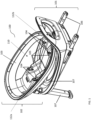
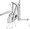
- the base 100 comprises a lower part 101 and an upper part 102 rotatably mounted to the lower part 101, wherein the upper part 102 is shaped to define a void 110 in which a car seat can be received.
- the upper part 102 comprises an annular member 103 surrounding the void and connection means 104 adapted for engagement with a securing means of the car seat.
- the annular member is generally elliptical in outline and is supported on supports 112a, 112b at the front and rear of the upper part 102 along the long (major) axis of the ellipse. It is otherwise unsupported.
- the annular member 103 is tilted with respect to the horizontal base by approximately 15 degrees.
- the base comprises two pairs of connection means 104 and two pairs of positioning projections 105 upon which the connection means 104 are located.
- the lower part 101 of the base 100 comprises ISOFIX arms 106 and a support leg 107.
- the lower part 101 further comprises a rotatable platform 108 upon which the upper part 102 is mounted.
- FIG 3 shows a car seat 200 for use with the base 100.
- the car seat 200 comprises a seat body 201 and a restraining bar 202.
- the seat body 201 comprises an installation channel 203 in which securing means 204 are located.
- This car seat is an infant child seat (Group 0 or 0+, for a child up to 10 or 13 kg).
- Figure 4 shows the car seat 200 installed in the base 100. It can be seen that the annular member 103 surrounds the car seat 200 although there is a gap 111 between the car seat 200 and the annular member 103 to allow the annular member 103 to flex.
- the kinetic energy of the car seat and its occupant will first be absorbed by the annular member 103 flexing. As the annular member is curved, it will resist any force perpendicular to it externally to the curve, such as being impacted from any side. Because those initial forces are absorbed by the annular member 103, there is less kinetic energy to dissipate and less force to resist for the car seat 200 itself. This means that the overall crash safety of the car seat in the base can be improved, and the required resistance to crashes of the car seat can be reduced, potentially meaning that it can be made lighter.
- FIG. 5 shows an alternative toddler car seat 400, and Figure 6 that car seat 400 installed in the base 100.
- the car seat comprises a seat body 401.
- the seat body 401 comprises an installation channel 402 in which securing means 403 are located.
- This car seat is larger - a "toddler" seat - for larger children (group 1, up to 18 kg).
- group 1, up to 18 kg children
- the base and the annular member work in the same way - the annular member 103 surrounds the seat 400 leaving a gap 111 to allow the annular member 103 to flex in the event of a crash.
Landscapes
- Engineering & Computer Science (AREA)
- Health & Medical Sciences (AREA)
- Child & Adolescent Psychology (AREA)
- General Health & Medical Sciences (AREA)
- Aviation & Aerospace Engineering (AREA)
- Transportation (AREA)
- Mechanical Engineering (AREA)
- Seats For Vehicles (AREA)
Abstract
Description
- This invention relates generally to car seats, and more particularly, a car seat system including a base on which a car seat may be detachably mounted.
- There are many known systems for mounting a car seat in a vehicle. Car seat systems having a separate base and car seat have been designed to allow parents to secure their infant or toddler car seat in the car easily and safely, without the need to carry the entire apparatus once the car seat is removed from the car.
- There is a continuing move towards improved safety in car seat systems for infants and young children. Several systems have been designed for improving crash resistance, however additional safety features often result in bulkier or heavier car seats, making removal of the car seat from the vehicle and subsequent carriage of the car seat more difficult for the user.
- It is an object of the invention to provide a system having improved crash resistance, whilst allowing for ergonomic use.
- A first aspect of the invention provides a base for a car seat comprising a lower part adapted to rest on a vehicle seat cushion; and an upper part rotatably mounted to the lower part, wherein the upper part is shaped to define a void in which a car seat can be received, the upper part comprising a support part, an annular member supported by the support part and surrounding the void and connection means on the support part adapted for engagement with a securing means of the car seat.
- As such, the annular member can serve to absorb energy in the case of a crash, thus improving the crash resistance of the car seat system as a whole. It can also allow a reduction in the amount of material required to form the car seat, as the annular member can provide some of the crash protection that would otherwise be provided by the car seat itself. This means that the car seat can be lighter and so easier to carry, as well as potentially being cheaper to make.
- The annular member may surround the car seat when it is received within the void. The annular member may comprise a circumference with the annular member being supported on the support part only by a plurality of supports spaced around the circumference. There may be precisely two supports.
- The connection means may define a forwards/backwards direction of the car seat; the annular member may have two extremes in the forwards/backwards direction, with a support being provided at each extreme. This provides extra strength in respect of collisions along the forwards/backwards direction (such as rear end shunts, a common form of crash).
- The annular member may be curved between the supports, and may be shaped as sections of an ellipse or circle. Doing so allows the annular member to absorb energy in a crash situation, as a curved member will resist any force perpendicular to it from the exterior of the curve.
- The lower part may lie in a first plane, and the annular member may lie in a second plane. The first plane may form a non-zero angle with the second plane; the angle may be at least 5, 10 or 15 degrees.
- The connection means may comprise at least one protrusion arranged to align the car seat in the void. The connection means may be located on the at least one protrusion.
- The upper part may be rotatably mounted on the lower part; this allows the car seat to be rotated to a convenient position (e.g., facing a door of the vehicle in which it is mounted) before the car seat is removed from the base.
- The lower part of the base may comprise means for securing the base within the vehicle. The lower part of the base may comprise means for securing the base into the vehicle using the vehicle safety belt fixings. Alternatively, the lower part of the base may comprise ISOFIX arms. The lower part of the base may comprise a support leg. The lower part of the base may preferably comprise ISOFIX arms and a support leg. In some preferred embodiments the base may be secured inside the vehicle by fixing into ISOFIX anchor points inside the car, with the infant or child car seat then attaching to the base.
- A second aspect of the invention provides a car seat system comprising a base in accordance with the first aspect of the invention and a car seat received in the void.
- The car seat may comprise securing means engaged with the connection means. For example, the securing means may comprise a bar and the connection means may comprise a catch, with the bar being received within the catch.
- The connection means of the upper part of the base may be configured so that upon engagement with the securing means of the car seat, the car seat is locked in a fixed position within the void of the upper part of the base. This position may be such that there is a gap between the annular member and the car seat; typically, this gap will be at least 5mm, 10mm, 20mm or 30mm.
- The upper part of the base may comprise positioning projections adapted for alignment with an installation channel of the car seat. The positioning projections may be configured such that alignment within the installation channel of the car seat enables the user to guide the car seat into the correct position within the upper part of the base to enable the car seat to be locked in the affixed position via engagement of the connection means of the base with the securing means of the car seat.
- The lower part of the base may comprise any suitable means for securing the base within the vehicle. The lower part of the base may comprise means for securing the base into the vehicle using the vehicle safety belt fixings. Alternatively, the lower part of the base may comprise ISOFIX arms. The lower part of the base may comprise a support leg. The lower part of the base may preferably comprise ISOFIX arms and a support leg. In some preferred embodiments the base may be secured inside the vehicle by fixing into ISOFIX anchor points inside the car, with the infant or child car seat then attaching to the base.
- A third aspect of the invention provides a car seat kit, comprising at least two car seats each having securing means and a base in accordance with the first aspect of the invention, in which the securing means of each car seats can engage the connection means of the base, and in which the car seats are for different-sized children.
- For example, one car seat could be for children of from birth up to 10 or 13 kg, and another car seat could be for children from 9 kg to 18 or 36 kg.
- As such, this allows the same base to be used with car seats for children of different sizes.
- There now follows, by way of example only, description of an embodiment of the invention described with reference to the accompanying drawings, in which:
- FIG. 1
- is a perspective view of a base for a car seat according to an embodiment of the invention;
- FIG. 2
- is a side view of the base of
Figure 1 ; - FIG. 3
- is a rear perspective view of an infant car seat installed in the base of
Figure 1 ; - FIG. 4
- is a side view of the base and car seat of
Figure 3 ; - FIG. 5
- is a perspective view of a toddler car seat for use with the embodiment of
Figure 1 ; and - FIG. 6
- is a perspective view of the toddler car seat of
Figure 5 installed in the base ofFigure 1 . - As shown in
figures 1 and2 of the accompanying drawings, thebase 100 comprises alower part 101 and anupper part 102 rotatably mounted to thelower part 101, wherein theupper part 102 is shaped to define avoid 110 in which a car seat can be received. Theupper part 102 comprises anannular member 103 surrounding the void and connection means 104 adapted for engagement with a securing means of the car seat. - The annular member is generally elliptical in outline and is supported on
supports upper part 102 along the long (major) axis of the ellipse. It is otherwise unsupported. - The
annular member 103 is tilted with respect to the horizontal base by approximately 15 degrees. - In this embodiment, the base comprises two pairs of connection means 104 and two pairs of
positioning projections 105 upon which the connection means 104 are located. Thelower part 101 of thebase 100 comprises ISOFIXarms 106 and asupport leg 107. Thelower part 101 further comprises a rotatable platform 108 upon which theupper part 102 is mounted. -
Figure 3 shows acar seat 200 for use with thebase 100. Thecar seat 200 comprises aseat body 201 and a restrainingbar 202. Theseat body 201 comprises aninstallation channel 203 in which securing means 204 are located. This car seat is an infant child seat (Group 0 or 0+, for a child up to 10 or 13 kg). -
Figure 4 shows thecar seat 200 installed in thebase 100. It can be seen that theannular member 103 surrounds thecar seat 200 although there is agap 111 between thecar seat 200 and theannular member 103 to allow theannular member 103 to flex. - Thus, should the vehicle carrying the car seat be in a crash, the kinetic energy of the car seat and its occupant will first be absorbed by the
annular member 103 flexing. As the annular member is curved, it will resist any force perpendicular to it externally to the curve, such as being impacted from any side. Because those initial forces are absorbed by theannular member 103, there is less kinetic energy to dissipate and less force to resist for thecar seat 200 itself. This means that the overall crash safety of the car seat in the base can be improved, and the required resistance to crashes of the car seat can be reduced, potentially meaning that it can be made lighter. -
Figure 5 shows an alternativetoddler car seat 400, andFigure 6 thatcar seat 400 installed in thebase 100. The car seat comprises aseat body 401. Theseat body 401 comprises aninstallation channel 402 in which securing means 403 are located. This car seat is larger - a "toddler" seat - for larger children (group 1, up to 18 kg). However, the base and the annular member work in the same way - theannular member 103 surrounds theseat 400 leaving agap 111 to allow theannular member 103 to flex in the event of a crash.
Claims (11)
- A base for a car seat comprising a lower part adapted to rest on a vehicle seat cushion; and an upper part rotatably mounted to the lower part, wherein the upper part is shaped to define a void in which a car seat can be received, the upper part comprising a support part, an annular member supported by the support part and surrounding the void and connection means on the support part adapted for engagement with a securing means of the car seat.
- The base of claim 1, in which the annular member surrounds the car seat when it is received within the void.
- The base of claim 1 or claim 2, in which the annular member comprises a circumference with the annular member being supported on the support part only by a plurality of supports spaced around the circumference.
- The base of claim 3, in which the connection means defines a forwards/backwards direction of the car seat; the annular member has two extremes in the forwards/backwards direction, and a support is provided at each extreme.
- The base of claim 3 or claim 4, in which the annular member is curved between the supports.
- The base of any preceding claim, in which the lower part lies in a first plane, and the annular member lies in a second plane, the first plane forming a non-zero angle with the second plane.
- The base of claim 6 in which the angle is at least 5, 10 or 15 degrees.
- A car seat system comprising a base in accordance with any preceding claim and a car seat received in the void.
- The system of claim 8, in which the car seat comprises securing means engaged with the connection means.
- The system of claim 8 or claim 9, in which the connection means of the upper part of the base is configured so that upon engagement with the securing means of the car seat, the car seat is locked in a fixed position within the void of the upper part of the base, with the fixed position being such that there is a gap between the annular member and the car seat.
- A car seat kit, comprising at least two car seats each having securing means and a base in accordance any of claims 1 to 7, in which the securing means of each car seats can engage the connection means of the base, and in which the car seats are for different-sized children.
Applications Claiming Priority (1)
| Application Number | Priority Date | Filing Date | Title |
|---|---|---|---|
| GB2215158.3A GB2623504A (en) | 2022-10-13 | 2022-10-13 | Car seats, bases and systems |
Publications (2)
| Publication Number | Publication Date |
|---|---|
| EP4353529A1 true EP4353529A1 (en) | 2024-04-17 |
| EP4353529B1 EP4353529B1 (en) | 2026-04-15 |
Family
ID=84818180
Family Applications (1)
| Application Number | Title | Priority Date | Filing Date |
|---|---|---|---|
| EP23203600.4A Active EP4353529B1 (en) | 2022-10-13 | 2023-10-13 | Car seat systems |
Country Status (3)
| Country | Link |
|---|---|
| EP (1) | EP4353529B1 (en) |
| CN (1) | CN117885618A (en) |
| GB (1) | GB2623504A (en) |
Citations (2)
| Publication number | Priority date | Publication date | Assignee | Title |
|---|---|---|---|---|
| EP2616271B1 (en) * | 2010-09-14 | 2015-04-15 | CYBEX Industrial Ltd. | Child seat |
| EP3798049A1 (en) * | 2019-09-27 | 2021-03-31 | Transtek Industries (HK) Limited | Manipulation assembly for safety seat base, and safety seat base, kit and manipulation method |
Family Cites Families (4)
| Publication number | Priority date | Publication date | Assignee | Title |
|---|---|---|---|---|
| US20080067845A1 (en) * | 2006-02-28 | 2008-03-20 | Britax Child Safety, Inc. | Carry handle seat latch for child safety seat |
| US11034266B2 (en) * | 2019-02-27 | 2021-06-15 | Dorel Juvenile Group, Inc. | Child restraint |
| NL2023469B1 (en) * | 2019-07-10 | 2021-02-02 | Maxi Miliaan Bv | Child seat transporting system and safety part suitable for such a child seat transporting system |
| NL2023470B1 (en) * | 2019-07-10 | 2021-02-02 | Maxi Miliaan Bv | Coupling mechanism as well as a child seat transporting system provided with at least one such a coupling mechanism |
-
2022
- 2022-10-13 GB GB2215158.3A patent/GB2623504A/en active Pending
-
2023
- 2023-10-13 CN CN202311323861.9A patent/CN117885618A/en active Pending
- 2023-10-13 EP EP23203600.4A patent/EP4353529B1/en active Active
Patent Citations (2)
| Publication number | Priority date | Publication date | Assignee | Title |
|---|---|---|---|---|
| EP2616271B1 (en) * | 2010-09-14 | 2015-04-15 | CYBEX Industrial Ltd. | Child seat |
| EP3798049A1 (en) * | 2019-09-27 | 2021-03-31 | Transtek Industries (HK) Limited | Manipulation assembly for safety seat base, and safety seat base, kit and manipulation method |
Also Published As
| Publication number | Publication date |
|---|---|
| CN117885618A (en) | 2024-04-16 |
| GB2623504A (en) | 2024-04-24 |
| GB202215158D0 (en) | 2022-11-30 |
| EP4353529B1 (en) | 2026-04-15 |
Similar Documents
| Publication | Publication Date | Title |
|---|---|---|
| AU2018278936C1 (en) | Child safety seat | |
| US7909400B1 (en) | Modular child safety seat for vehicles | |
| US10780800B2 (en) | Child safety seat with anti-rotation device | |
| EP2550178B1 (en) | Reclining ride down child seat | |
| US12415444B2 (en) | Rotatable car seat and base | |
| CN104602952B (en) | Child safety seats and side impact protection | |
| CA3073145C (en) | Child safety seat | |
| US9022463B2 (en) | Rear-seat armrest locking apparatus | |
| JP5547119B2 (en) | Safety child seat with structural support | |
| EP1893454B1 (en) | Restraining | |
| EP3554889B1 (en) | Child safety seat for a vehicle | |
| KR20160058169A (en) | Child safety seat | |
| EP3853066B1 (en) | Child safety seat with side impact energy absorption | |
| KR20140019287A (en) | Rotating child safety seat | |
| CN112829708B (en) | Wheelchair passenger restraint structure | |
| EP4353529A1 (en) | Car seats, bases and systems | |
| US10899252B2 (en) | Child safety seat with belted pivot link | |
| JP6495942B2 (en) | Restraint member | |
| GB2366194A (en) | A child safety seat with moveable leg support | |
| US20160304005A1 (en) | Vehicle seat assembly accommodating a rear facing child seat | |
| TW202606906A (en) | Rotatable child seat with removable booster | |
| KR20210115876A (en) | Foldable safety seat for easy installation and storage and improved safety. | |
| HK40105682A (en) | Juvenile vehicle seat system |
Legal Events
| Date | Code | Title | Description |
|---|---|---|---|
| PUAI | Public reference made under article 153(3) epc to a published international application that has entered the european phase |
Free format text: ORIGINAL CODE: 0009012 |
|
| STAA | Information on the status of an ep patent application or granted ep patent |
Free format text: STATUS: THE APPLICATION HAS BEEN PUBLISHED |
|
| AK | Designated contracting states |
Kind code of ref document: A1 Designated state(s): AL AT BE BG CH CY CZ DE DK EE ES FI FR GB GR HR HU IE IS IT LI LT LU LV MC ME MK MT NL NO PL PT RO RS SE SI SK SM TR |
|
| STAA | Information on the status of an ep patent application or granted ep patent |
Free format text: STATUS: REQUEST FOR EXAMINATION WAS MADE |
|
| 17P | Request for examination filed |
Effective date: 20241016 |
|
| RBV | Designated contracting states (corrected) |
Designated state(s): AL AT BE BG CH CY CZ DE DK EE ES FI FR GB GR HR HU IE IS IT LI LT LU LV MC ME MK MT NL NO PL PT RO RS SE SI SK SM TR |
|
| GRAP | Despatch of communication of intention to grant a patent |
Free format text: ORIGINAL CODE: EPIDOSNIGR1 |
|
| STAA | Information on the status of an ep patent application or granted ep patent |
Free format text: STATUS: GRANT OF PATENT IS INTENDED |
|
| INTG | Intention to grant announced |
Effective date: 20251125 |
|
| GRAS | Grant fee paid |
Free format text: ORIGINAL CODE: EPIDOSNIGR3 |
|
| GRAA | (expected) grant |
Free format text: ORIGINAL CODE: 0009210 |
|
| STAA | Information on the status of an ep patent application or granted ep patent |
Free format text: STATUS: THE PATENT HAS BEEN GRANTED |
|
| AK | Designated contracting states |
Kind code of ref document: B1 Designated state(s): AL AT BE BG CH CY CZ DE DK EE ES FI FR GB GR HR HU IE IS IT LI LT LU LV MC ME MK MT NL NO PL PT RO RS SE SI SK SM TR |
|
| REG | Reference to a national code |
Ref country code: CH Ref legal event code: F10 Free format text: ST27 STATUS EVENT CODE: U-0-0-F10-F00 (AS PROVIDED BY THE NATIONAL OFFICE) Effective date: 20260415 |