EP4353519A1 - Power adapter and method therefor, electric vehicle and method therefor - Google Patents
Power adapter and method therefor, electric vehicle and method therefor Download PDFInfo
- Publication number
- EP4353519A1 EP4353519A1 EP23200381.4A EP23200381A EP4353519A1 EP 4353519 A1 EP4353519 A1 EP 4353519A1 EP 23200381 A EP23200381 A EP 23200381A EP 4353519 A1 EP4353519 A1 EP 4353519A1
- Authority
- EP
- European Patent Office
- Prior art keywords
- adapter
- power
- electric vehicle
- charging interface
- battery pack
- Prior art date
- Legal status (The legal status is an assumption and is not a legal conclusion. Google has not performed a legal analysis and makes no representation as to the accuracy of the status listed.)
- Pending
Links
Images


Classifications
-
- B—PERFORMING OPERATIONS; TRANSPORTING
- B60—VEHICLES IN GENERAL
- B60L—PROPULSION OF ELECTRICALLY-PROPELLED VEHICLES; SUPPLYING ELECTRIC POWER FOR AUXILIARY EQUIPMENT OF ELECTRICALLY-PROPELLED VEHICLES; ELECTRODYNAMIC BRAKE SYSTEMS FOR VEHICLES IN GENERAL; MAGNETIC SUSPENSION OR LEVITATION FOR VEHICLES; MONITORING OPERATING VARIABLES OF ELECTRICALLY-PROPELLED VEHICLES; ELECTRIC SAFETY DEVICES FOR ELECTRICALLY-PROPELLED VEHICLES
- B60L53/00—Methods of charging batteries, specially adapted for electric vehicles; Charging stations or on-board charging equipment therefor; Exchange of energy storage elements in electric vehicles
- B60L53/10—Methods of charging batteries, specially adapted for electric vehicles; Charging stations or on-board charging equipment therefor; Exchange of energy storage elements in electric vehicles characterised by the energy transfer between the charging station and the vehicle
- B60L53/14—Conductive energy transfer
- B60L53/16—Connectors, e.g. plugs or sockets, specially adapted for charging electric vehicles
-
- H—ELECTRICITY
- H02—GENERATION; CONVERSION OR DISTRIBUTION OF ELECTRIC POWER
- H02J—ELECTRIC POWER NETWORKS; CIRCUIT ARRANGEMENTS OR SYSTEMS FOR SUPPLYING OR DISTRIBUTING ELECTRIC POWER; SYSTEMS FOR STORING ELECTRIC ENERGY
- H02J7/00—Circuit arrangements for charging or discharging batteries or for supplying loads from batteries
- H02J7/70—Circuit arrangements for charging or discharging batteries or for supplying loads from batteries characterised by the mechanical construction
-
- B—PERFORMING OPERATIONS; TRANSPORTING
- B60—VEHICLES IN GENERAL
- B60L—PROPULSION OF ELECTRICALLY-PROPELLED VEHICLES; SUPPLYING ELECTRIC POWER FOR AUXILIARY EQUIPMENT OF ELECTRICALLY-PROPELLED VEHICLES; ELECTRODYNAMIC BRAKE SYSTEMS FOR VEHICLES IN GENERAL; MAGNETIC SUSPENSION OR LEVITATION FOR VEHICLES; MONITORING OPERATING VARIABLES OF ELECTRICALLY-PROPELLED VEHICLES; ELECTRIC SAFETY DEVICES FOR ELECTRICALLY-PROPELLED VEHICLES
- B60L1/00—Supplying electric power to auxiliary equipment of vehicles
- B60L1/006—Supplying electric power to auxiliary equipment of vehicles to power outlets
-
- B—PERFORMING OPERATIONS; TRANSPORTING
- B60—VEHICLES IN GENERAL
- B60L—PROPULSION OF ELECTRICALLY-PROPELLED VEHICLES; SUPPLYING ELECTRIC POWER FOR AUXILIARY EQUIPMENT OF ELECTRICALLY-PROPELLED VEHICLES; ELECTRODYNAMIC BRAKE SYSTEMS FOR VEHICLES IN GENERAL; MAGNETIC SUSPENSION OR LEVITATION FOR VEHICLES; MONITORING OPERATING VARIABLES OF ELECTRICALLY-PROPELLED VEHICLES; ELECTRIC SAFETY DEVICES FOR ELECTRICALLY-PROPELLED VEHICLES
- B60L53/00—Methods of charging batteries, specially adapted for electric vehicles; Charging stations or on-board charging equipment therefor; Exchange of energy storage elements in electric vehicles
- B60L53/30—Constructional details of charging stations
-
- B—PERFORMING OPERATIONS; TRANSPORTING
- B60—VEHICLES IN GENERAL
- B60L—PROPULSION OF ELECTRICALLY-PROPELLED VEHICLES; SUPPLYING ELECTRIC POWER FOR AUXILIARY EQUIPMENT OF ELECTRICALLY-PROPELLED VEHICLES; ELECTRODYNAMIC BRAKE SYSTEMS FOR VEHICLES IN GENERAL; MAGNETIC SUSPENSION OR LEVITATION FOR VEHICLES; MONITORING OPERATING VARIABLES OF ELECTRICALLY-PROPELLED VEHICLES; ELECTRIC SAFETY DEVICES FOR ELECTRICALLY-PROPELLED VEHICLES
- B60L55/00—Arrangements for supplying energy stored within a vehicle to a power network, i.e. vehicle-to-grid [V2G] arrangements
-
- B—PERFORMING OPERATIONS; TRANSPORTING
- B60—VEHICLES IN GENERAL
- B60L—PROPULSION OF ELECTRICALLY-PROPELLED VEHICLES; SUPPLYING ELECTRIC POWER FOR AUXILIARY EQUIPMENT OF ELECTRICALLY-PROPELLED VEHICLES; ELECTRODYNAMIC BRAKE SYSTEMS FOR VEHICLES IN GENERAL; MAGNETIC SUSPENSION OR LEVITATION FOR VEHICLES; MONITORING OPERATING VARIABLES OF ELECTRICALLY-PROPELLED VEHICLES; ELECTRIC SAFETY DEVICES FOR ELECTRICALLY-PROPELLED VEHICLES
- B60L58/00—Methods or circuit arrangements for monitoring or controlling batteries or fuel cells, specially adapted for electric vehicles
- B60L58/10—Methods or circuit arrangements for monitoring or controlling batteries or fuel cells, specially adapted for electric vehicles for monitoring or controlling batteries
- B60L58/12—Methods or circuit arrangements for monitoring or controlling batteries or fuel cells, specially adapted for electric vehicles for monitoring or controlling batteries responding to state of charge [SoC]
- B60L58/14—Preventing excessive discharging
-
- H—ELECTRICITY
- H02—GENERATION; CONVERSION OR DISTRIBUTION OF ELECTRIC POWER
- H02J—ELECTRIC POWER NETWORKS; CIRCUIT ARRANGEMENTS OR SYSTEMS FOR SUPPLYING OR DISTRIBUTING ELECTRIC POWER; SYSTEMS FOR STORING ELECTRIC ENERGY
- H02J7/00—Circuit arrangements for charging or discharging batteries or for supplying loads from batteries
- H02J7/40—Circuit arrangements for charging or discharging batteries or for supplying loads from batteries characterised by the exchange of charge or discharge related data
-
- H—ELECTRICITY
- H02—GENERATION; CONVERSION OR DISTRIBUTION OF ELECTRIC POWER
- H02J—ELECTRIC POWER NETWORKS; CIRCUIT ARRANGEMENTS OR SYSTEMS FOR SUPPLYING OR DISTRIBUTING ELECTRIC POWER; SYSTEMS FOR STORING ELECTRIC ENERGY
- H02J7/00—Circuit arrangements for charging or discharging batteries or for supplying loads from batteries
- H02J7/90—Regulation of charging or discharging current or voltage
- H02J7/933—Regulation of charging or discharging current or voltage the cycle being controlled or terminated in response to electric parameters
-
- H—ELECTRICITY
- H02—GENERATION; CONVERSION OR DISTRIBUTION OF ELECTRIC POWER
- H02M—APPARATUS FOR CONVERSION BETWEEN AC AND AC, BETWEEN AC AND DC, OR BETWEEN DC AND DC, AND FOR USE WITH MAINS OR SIMILAR POWER SUPPLY SYSTEMS; CONVERSION OF DC OR AC INPUT POWER INTO SURGE OUTPUT POWER; CONTROL OR REGULATION THEREOF
- H02M3/00—Conversion of DC power input into DC power output
- H02M3/02—Conversion of DC power input into DC power output without intermediate conversion into AC
- H02M3/04—Conversion of DC power input into DC power output without intermediate conversion into AC by static converters
-
- H—ELECTRICITY
- H02—GENERATION; CONVERSION OR DISTRIBUTION OF ELECTRIC POWER
- H02M—APPARATUS FOR CONVERSION BETWEEN AC AND AC, BETWEEN AC AND DC, OR BETWEEN DC AND DC, AND FOR USE WITH MAINS OR SIMILAR POWER SUPPLY SYSTEMS; CONVERSION OF DC OR AC INPUT POWER INTO SURGE OUTPUT POWER; CONTROL OR REGULATION THEREOF
- H02M3/00—Conversion of DC power input into DC power output
- H02M3/22—Conversion of DC power input into DC power output with intermediate conversion into AC
- H02M3/24—Conversion of DC power input into DC power output with intermediate conversion into AC by static converters
-
- H—ELECTRICITY
- H02—GENERATION; CONVERSION OR DISTRIBUTION OF ELECTRIC POWER
- H02M—APPARATUS FOR CONVERSION BETWEEN AC AND AC, BETWEEN AC AND DC, OR BETWEEN DC AND DC, AND FOR USE WITH MAINS OR SIMILAR POWER SUPPLY SYSTEMS; CONVERSION OF DC OR AC INPUT POWER INTO SURGE OUTPUT POWER; CONTROL OR REGULATION THEREOF
- H02M7/00—Conversion of AC power input into DC power output; Conversion of DC power input into AC power output
- H02M7/02—Conversion of AC power input into DC power output without possibility of reversal
- H02M7/04—Conversion of AC power input into DC power output without possibility of reversal by static converters
-
- B—PERFORMING OPERATIONS; TRANSPORTING
- B60—VEHICLES IN GENERAL
- B60L—PROPULSION OF ELECTRICALLY-PROPELLED VEHICLES; SUPPLYING ELECTRIC POWER FOR AUXILIARY EQUIPMENT OF ELECTRICALLY-PROPELLED VEHICLES; ELECTRODYNAMIC BRAKE SYSTEMS FOR VEHICLES IN GENERAL; MAGNETIC SUSPENSION OR LEVITATION FOR VEHICLES; MONITORING OPERATING VARIABLES OF ELECTRICALLY-PROPELLED VEHICLES; ELECTRIC SAFETY DEVICES FOR ELECTRICALLY-PROPELLED VEHICLES
- B60L2210/00—Converter types
- B60L2210/30—AC to DC converters
-
- Y—GENERAL TAGGING OF NEW TECHNOLOGICAL DEVELOPMENTS; GENERAL TAGGING OF CROSS-SECTIONAL TECHNOLOGIES SPANNING OVER SEVERAL SECTIONS OF THE IPC; TECHNICAL SUBJECTS COVERED BY FORMER USPC CROSS-REFERENCE ART COLLECTIONS [XRACs] AND DIGESTS
- Y02—TECHNOLOGIES OR APPLICATIONS FOR MITIGATION OR ADAPTATION AGAINST CLIMATE CHANGE
- Y02T—CLIMATE CHANGE MITIGATION TECHNOLOGIES RELATED TO TRANSPORTATION
- Y02T10/00—Road transport of goods or passengers
- Y02T10/60—Other road transportation technologies with climate change mitigation effect
- Y02T10/70—Energy storage systems for electromobility, e.g. batteries
-
- Y—GENERAL TAGGING OF NEW TECHNOLOGICAL DEVELOPMENTS; GENERAL TAGGING OF CROSS-SECTIONAL TECHNOLOGIES SPANNING OVER SEVERAL SECTIONS OF THE IPC; TECHNICAL SUBJECTS COVERED BY FORMER USPC CROSS-REFERENCE ART COLLECTIONS [XRACs] AND DIGESTS
- Y02—TECHNOLOGIES OR APPLICATIONS FOR MITIGATION OR ADAPTATION AGAINST CLIMATE CHANGE
- Y02T—CLIMATE CHANGE MITIGATION TECHNOLOGIES RELATED TO TRANSPORTATION
- Y02T10/00—Road transport of goods or passengers
- Y02T10/60—Other road transportation technologies with climate change mitigation effect
- Y02T10/7072—Electromobility specific charging systems or methods for batteries, ultracapacitors, supercapacitors or double-layer capacitors
Definitions
- the present disclosure relates to the technical field of electric vehicles, and in particular to a power adapter, an electric vehicle, a method for the power adapter, and a method for the electric vehicle.
- An electric vehicle is a vehicle powered by a vehicle power supply. Electric energy may be stored in a battery pack of the electric vehicle, and the electric energy may be transferred from the battery pack to a motor and a power transmission system by means of an electric governor, thus driving the vehicle to run.
- the electric vehicle may be provided with one or more charging interfaces.
- the electric vehicle may include an AC charging interface and a DC charging interface, wherein the AC charging interface may be called as an AC slow charging interface, and the DC charging interface may be called as a DC fast charging interface.
- a power adapter for converting DC power from an electric vehicle to AC power to supply power to an electrical load.
- the power adapter includes: an adapter plug for coupling a DC charging interface of the electric vehicle to obtain the DC power from a battery pack of the electric vehicle; an adapter socket for coupling the electrical load to supply the AC power to the electrical load; a locking assembly including a snap-on structure for mechanically locking the adapter plug to the DC charging interface when the adapter plug is coupled to the DC charging interface; and an adapter circuitry electrically connected between the adapter plug and the adapter socket.
- the adapter circuitry includes: a DC-AC converter configured to convert the DC power to the AC power; a first resistor and a first switch connected in series between a connection confirmation terminal CC2 and an earthing terminal PE of the adapter circuitry; and an adapter controller configured to i) close the first switch when the adapter plug is mechanically locked to the DC charging interface to generate a first triggering signal at the connection confirmation terminal CC2, the first triggering signal to be detected by the electric vehicle to indicate a discharging mode to the electric vehicle, and to ii) open the first switch when the adapter plug is unlocked from the DC charging interface to generate a second triggering signal at the connection confirmation terminal CC2, the second triggering signal to be detected by the electric vehicle to cause the electric vehicle to stop supplying the DC power to the power adapter.
- a DC-AC converter configured to convert the DC power to the AC power
- a first resistor and a first switch connected in series between a connection confirmation terminal CC2 and an earthing terminal PE of the adapter circuitry
- an electric vehicle including: a battery pack; a DC charging interface for coupling the battery pack and the adapter plug of the power adapter described above, to supply DC power from the battery pack to the adapter plug; and a vehicle controller configured to cause the battery pack to stop supplying the DC power to the power adapter in response to detecting the second triggering signal.
- a method for the power adapter described above including: causing the first switch to close in response to that the adapter plug is mechanically locked to the DC charging interface, so as to generate a first triggering signal at the connection confirmation terminal CC2, the first triggering signal to be detected by the electric vehicle to indicate a discharging mode to the electric vehicle; and causing the first switch to open when the adapter plug is unlocked from the DC charging interface, to generate a second triggering signal at the connection confirmation terminal CC2, the second triggering signal to be detected by the electric vehicle to cause the electric vehicle to stop supplying the DC power to the power adapter.
- a method for the electric vehicle described above including: causing the battery pack to stop supplying the DC power to the power adapter in response to detecting the second triggering signal.
- first, second, etc. used to describe various elements are not intended to limit the positional, temporal or importance relationship of these elements, but rather only to distinguish one component from another.
- first element and the second element may refer to the same instance of the element, and in some cases, based on contextual descriptions, the first element and the second element may also refer to different instances.
- vehicle or other similar terms used herein generally include motor vehicles, such as passenger vehicles including sedan cars, sport utility vehicles (SUVs), buses, vans, and various commercial vehicles, include boats, ships, aircraft, or the like, and include hybrid vehicles, electric vehicles, plug-in hybrid electric vehicles, hydrogen powered vehicles, and other alternative fuel vehicles (e.g., fuels derived from sources other than petroleum).
- motor vehicles such as passenger vehicles including sedan cars, sport utility vehicles (SUVs), buses, vans, and various commercial vehicles, include boats, ships, aircraft, or the like, and include hybrid vehicles, electric vehicles, plug-in hybrid electric vehicles, hydrogen powered vehicles, and other alternative fuel vehicles (e.g., fuels derived from sources other than petroleum).
- a battery pack of an electric vehicle may supply power to a motor and a power transmission system of the electric vehicle, thereby driving the vehicle to run.
- the battery pack of the electric vehicle may be used to supply power to an electrical load, thus providing charging conditions for the electrical load anytime, anywhere.
- An AC charging interface and a DC charging interface on the electric vehicle provide channels for the electric vehicle to discharge to the outside.
- an AC charging pile may be connected to the AC charging interface of the vehicle by means of a charging cable, AC (for example, 220 V AC) is boosted and rectified into high voltage DC by using an on-board charger of the electric vehicle, and then the high voltage DC is stored in the battery pack. In the process of AC charging, the conversion from AC to DC is completed by the on-board charger.
- AC for example, 220 V AC
- the AC charging interface on the electric vehicle may be used to discharge to the outside for use by the electrical load.
- the power adapter is coupled to the AC charging interface of the electric vehicle after the electrical load is coupled to the power adapter, and by setting a discharging mode for the vehicle, power can be supplied to the electrical load by means of the AC charging interface.
- the on-board charger may convert the high voltage DC provided by the battery pack into AC required by the electrical load, and due to the relatively low voltage at the AC charging interface (for example, the voltage is 220 V), the design of the power adapter for the AC charging interface may be relatively simple.
- DC charging pile may be connected to the DC charging interface of the vehicle by means of a charging cable, so as to directly charge the battery pack. It can be seen that the on-board charger does not need to be involved in the DC charging process since the charging pile has converted AC into DC. It should be noted that DC charging usually has a high voltage (for example, 300 V), and its current is also heavier than that of AC charging.
- Embodiments of the present disclosure provide a power adapter, an electric vehicle, a method for the power adapter, and a method for the electric vehicle. According to the embodiments of the present disclosure, a safe and reliable power supply can be provided from the DC charging interface of the electric vehicle to the electrical load outside the vehicle.
- FIG. 1 is a schematic diagram of an application scenario 100 of a power adapter and an electric vehicle according to an example embodiment.
- the application scenario 100 includes a vehicle 110, a power adapter 120 and an electrical load 130.
- the vehicle 110 includes an AC charging interface 111 and a DC charging interface 112.
- the power adapter 120 may be coupled to the DC charging interface 112 and may also be coupled to the electrical load 130, so as to transfer DC power provided by the vehicle 110 to the electrical load 130.
- the electrical load 130 may be a computer, a cell phone, a lighting device, a music player, a coffee machine, or the like.
- FIG. 2A is a schematic structure diagram of a power adapter 200 according to an example embodiment
- FIG. 2B is another schematic structure diagram of the power adapter 200 in FIG. 2A according to an example embodiment
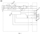
- FIG. 3 is a schematic diagram of an adapter circuitry 300 of the power adapter 200 according to an example embodiment.
- the power adapter 200 includes:
- the shape of the adapter plug 210 may be designed to match the DC charging interface of the vehicle, so that the adapter plug may be successfully coupled to the DC charging interface.
- the shape of the adapter socket 220 may be designed to match a plug of the electrical load, so that the adapter socket may be successfully coupled to the plug of the electrical load.
- the left side of the adapter circuitry 300 may be coupled to a terminal of the adapter socket; and the right side of the adapter circuitry 300 may be coupled to a terminal of the adapter plug.
- 9 terminals of the adapter circuitry 300 are shown, namely, a DC power supply terminal DC+/DC-; an earthing terminal PE; a message interactive communication terminal S+/S-; a connection confirmation terminal CC1/CC2; and a low voltage auxiliary terminal A+/A-. Accordingly, it can be seen from FIG. 2A that the adapter plug 210 is provided with corresponding positions for the 9 terminals described above.
- the adapter controller 340 may be coupled to the snap-on structure 231, and may trigger the first switch 330 to close when the snap-on structure 231 performs mechanical locking or finishes mechanical locking.
- the closing of the first switch 330 means that the first resistor 320 is connected between the earthing terminal PE and the connection confirmation terminal CC2, so as to generate the first triggering signal at the connection confirmation terminal CC2 (for example, causing a current change, a voltage change, or a resistance change in the connection confirmation circuit CC2).
- the adapter plug 210 When the adapter plug 210 is coupled to the DC charging interface of the vehicle, the electric vehicle may detect the first triggering signal by means of the corresponding connection confirmation terminal CC2 of the DC charging interface.
- a specific voltage value or voltage variation is detected, and the specific voltage value or voltage variation indicates a discharging mode of the vehicle, so that when a plug is plugged into the DC charging interface of the vehicle, the vehicle may "know" that discharging to the plug rather than charging from the plug may be performed, which is beneficial for the safety of the vehicle in supplying power to, or charging the vehicle from, the outside.
- the adapter controller 340 may be coupled to, for example, the snap-on structure 231, and trigger the first switch 330 to open when the snap-on structure 231 performs unlocking.
- the opening of the first switch 330 means that the first resistor 320 is disconnected between the earthing terminal PE and the connection confirmation terminal CC2, so as to generate the second triggering signal at the connection confirmation terminal CC2 (for example, causing a current change, a voltage change, or a resistance change in the connection confirmation circuit CC2).
- the electric vehicle may detect the second triggering signal by means of the corresponding connection confirmation terminal CC2 of the DC charging interface. For example, a specific voltage value or voltage variation is detected, and the specific voltage value or voltage variation instructs the vehicle to stop supplying the DC power to the power adapter 200.
- the locking assembly may realize locking or unlocking between the power adapter and the DC charging interface of the vehicle; and further, by means of the first switch and the first resistor, when the adapter plug 210 is locked to or unlocked from the DC charging interface of the vehicle, the first triggering signal and the second triggering signal may be provided to the electric vehicle, so that the electric vehicle may "know” in a timely manner that it should enter the discharging mode or power off the power adapter in a timely manner, thereby providing a safe and reliable power supply from the DC charging interface of the electric vehicle to the electrical load outside the vehicle.
- the vehicle may stop providing DC power in a timely manner to avoid "arc discharge" when the adapter plug is unlocked from the DC charging interface of the vehicle.
- the power adapter 200 may further include a housing 240, the housing 240 defining the adapter plug 210 and the adapter socket 220 such that the power adapter 200 forms an integrated structure.
- both of the adapter plug 210 and the adapter socket 220 are defined by the housing 240, and the whole adapter 200 forms an integrated compact structure, which can improve the convenience of use of the power adapter 200.
- the power adapter 200 may further include a cover body (not shown in the figures), and the cover body may be installed at the housing 240 on one side of the adapter socket 220 for protecting the adapter socket 220 against damage or contamination.
- the power adapter 200 may further include a plurality of adapter sockets 220.
- the adapter socket 220 may be arranged on the lower side of the rear end of the housing 240, thereby further preventing dust or sundries from falling into the adapter socket 220.
- the material of the housing 240 may be rubber.
- the snap-on structure 231 may include a lock pin for snapping into a lock hasp disposed at the DC charging interface of the electric vehicle, thereby realizing locking between the adapter plug 210 and the DC charging interface.
- the snap-on structure 231 may include a lock hasp for a lock pin arranged at the DC charging interface of the electric vehicle to be snapped therein, thereby realizing locking between the adapter plug 210 and the DC charging interface.
- the locking assembly may further include an unlocking button 232, the unlocking button 232 being coupled to the snap-on structure 231 such that the snap-on structure 231 unlocks the adapter plug 210 from the DC charging interface when the unlocking button 232 is pressed.
- the unlocking button 232 when pressed, causes a third triggering signal to be generated, and the third triggering signal is detected by the adapter controller 340 such that the adapter controller generates a signal for opening the first switch 330.
- a pressing operation by a user enables the electric vehicle to cut off the DC power supply to the power adapter 200 while the adapter plug 210 is unlocked, which brings convenience for the user.
- the adapter controller 340 may start timing upon detection of the third triggering signal, and generate a signal for opening the first switch 330 after a preset time period (for example, 5 seconds of pressing), thereby avoiding unexpected stop of power supply caused by opening of the first switch 330 at unexpected time due to a user's misoperation.
- a preset time period for example, 5 seconds of pressing
- the power adapter 200 may be configured to receive a low voltage DC power provided by a low voltage power supply device of the electric vehicle through a low voltage auxiliary terminal A+/A- of the adapter circuitry when the adapter plug 210 is coupled to the DC charging interface, thereby supplying energy to the power adapter 200.
- the low voltage power supply device of the electric vehicle may provide low voltage power supply with a voltage of 12 V, and by means of the low voltage auxiliary terminal A+/A-, the power adapter 200 may receive the low voltage power supply for internal power supply to such as the adapter controller 340 and the first switch 330.
- the power adapter 200 may receive the low voltage power supply for internal power supply to such as the adapter controller 340 and the first switch 330.
- the low voltage power supply device of the electric vehicle may directly supply the low voltage DC power to the power adapter 200 without closing the first switch 330 as long as the adapter plug 210 is coupled to the DC charging interface, thus further ensuring power supply to the power adapter 200, such as the adapter controller 340 and the first switch 330.
- the adapter controller 340 may be further configured to send a first message to the electric vehicle during supplying power to the electrical load such that the electric vehicle can determine whether to stop supplying the DC power to the power adapter according to the first message, wherein the first message indicates at least one of: a present output voltage, a present output current and a cumulative output power of the adapter, or a state of the locking assembly.
- the first message may indicate the state of the locking assembly.
- a particular byte or a particular bit of the first message indicates an unlocked state of the locking assembly with 0 or 00 and indicates a locked state of the locking assembly with 1 or 01.
- the first message received by the electric vehicle during power supply indicates 0 or 00, it means that the locking assembly has been unlocked, so that the supply of DC power to the power adapter may be stopped.
- the first message may indicate the accumulative output power, and when the first message received by the electric vehicle during power supply indicates that the accumulative output power exceeds a threshold, the supply of DC power to the power adapter 200 may be stopped.
- the electric vehicle may further confirm, according to the message communication, whether the current conditions are suitable for discharging to the outside, which further improves the safety of discharging.
- the first message may be acquired by modifying a charger's charging status (CCS) message.
- CCS charger's charging status
- the adapter controller 340 may be further configured to send a second message to the electric vehicle in response to that a failure of the power adapter 200 is detected or the adapter plug 210 is unlocked from the DC charging interface, the second message indicating that the power adapter 200 will stop supplying power to the electrical load.
- the second message may be acquired by modifying a charging stop (CST) message.
- CST charging stop
- the reason why the power adapter 200 will stop supplying power to the electrical load may be recorded in the second message for analysis by the electric vehicle or for the next action.
- the adapter controller 340 may be further configured to:
- the third message may be acquired by modifying an overall battery charging status (BCS) message.
- the third message may indicate the voltage or electric quantity of the battery pack of the electric vehicle.
- the adapter controller 340 may stop supplying power to the electrical load, thus avoiding insufficient power remaining in the battery pack of the electric vehicle.
- first message, the second message, and the third message may all be transmitted between the power adapter 200 and the electric vehicle through the message interactive communication terminal S+/S- shown in FIG. 3 .
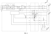
- FIG. 4 is a schematic circuitry diagram of coupling of an electric vehicle 400 to the power adapter according to an example embodiment.
- the electric vehicle 400 includes: a battery pack 410; a DC charging interface for coupling the battery pack and the adapter plug 210 of the power adapter 200 described above, to supply DC power from the battery pack 410 to the adapter plug 210; and a vehicle controller 420 configured to cause the battery pack 410 to stop supplying the DC power to the power adapter 200 in response to detecting the second triggering signal.
- FIG. 4 shows a schematic diagram of the adapter circuitry 300 of the power adapter 200 described above; and the right side of FIG. 4 shows a schematic circuitry diagram of the electric vehicle 400.
- the electric vehicle 400 includes a DC charging interface for coupling the adapter plug 210, the DC charging interface including 9 terminals, namely, a DC power supply terminal DC+/DC-; an earthing terminal PE; a message interactive communication terminal S+/S-; a connection confirmation terminal CC1/CC2; and a low voltage auxiliary terminal A+/A-.
- the vehicle controller 420 causes the battery pack 410 to stop supplying the DC power to the power adapter 200 in response to detecting the second triggering signal. For example, the vehicle controller 420 detects a specific voltage value or voltage variation, and the specific voltage value or voltage variation instructs the vehicle to stop supplying the DC power to the power adapter 200. In an example, the vehicle controller 420 may control a relay between the battery pack 410 and the DC power supply terminal DC+/DC- to switch off, so as to stop supplying the DC power to the power adapter 200. In an example, the vehicle controller 420 may detect the second triggering signal by detecting a voltage at a detection point U2 in FIG. 4 .
- a safe and reliable power supply can be provided from the DC charging interface of the electric vehicle to the electrical load outside the vehicle.
- the vehicle may stop providing DC power in a timely manner to avoid "arc discharge" when the adapter plug is unlocked from the DC charging interface of the vehicle.
- the electric vehicle 400 may further include a low voltage power supply device 430, and the low voltage power supply device 430 may provide low voltage DC power to the power adapter 200 through the low voltage auxiliary terminal A+/A- of the DC charging interface, thereby supplying energy to the power adapter 200.
- the vehicle controller 420 may be further configured to:
- the electric vehicle 400 may further confirm, based on the second triggering signal, the time to stop discharging to the outside, which further improves the safety of discharging.
- the vehicle controller 420 may be further configured to:
- the power adapter 200 may stop obtaining the DC power from the battery pack 410, thus avoiding insufficient power remaining in the battery pack of the electric vehicle.
- the vehicle controller 420 may be further configured to:
- the vehicle controller 420 may directly control the relay between the battery pack 410 and the DC power supply terminal DC+/DC- to switch off, thereby stopping supplying the DC power to the power adapter 200.
- the vehicle controller 420 may be further configured to send a fourth message to the power adapter 200 in response to detecting a failure of the electric vehicle 400, the fourth message indicating that the electric vehicle 400 will stop supplying power to the adapter.
- the fourth message may be acquired by modifying a charging stop message of a battery management system (BST).
- BST battery management system
- a method for the power adapter 200 described above includes the following steps:
- a method for the electric vehicle 400 described above includes: causing the battery pack 410 to stop supplying the DC power to the power adapter 200 in response to detecting the second triggering signal.
Landscapes
- Engineering & Computer Science (AREA)
- Power Engineering (AREA)
- Transportation (AREA)
- Mechanical Engineering (AREA)
- Life Sciences & Earth Sciences (AREA)
- Sustainable Development (AREA)
- Sustainable Energy (AREA)
- Charge And Discharge Circuits For Batteries Or The Like (AREA)
- Electric Propulsion And Braking For Vehicles (AREA)
Abstract
Description
- The present disclosure relates to the technical field of electric vehicles, and in particular to a power adapter, an electric vehicle, a method for the power adapter, and a method for the electric vehicle.
- An electric vehicle is a vehicle powered by a vehicle power supply. Electric energy may be stored in a battery pack of the electric vehicle, and the electric energy may be transferred from the battery pack to a motor and a power transmission system by means of an electric governor, thus driving the vehicle to run. The electric vehicle may be provided with one or more charging interfaces. For example, the electric vehicle may include an AC charging interface and a DC charging interface, wherein the AC charging interface may be called as an AC slow charging interface, and the DC charging interface may be called as a DC fast charging interface.
- Methods described in this section are not necessarily methods that have been previously conceived or employed. It should not be assumed that any of the methods described in this section is considered to be the prior art just because they are included in this section, unless otherwise indicated expressly. Similarly, the problem mentioned in this section should not be considered to be universally recognized in any prior art, unless otherwise indicated expressly.
- According to an aspect of the present disclosure, a power adapter is provided for converting DC power from an electric vehicle to AC power to supply power to an electrical load. The power adapter includes: an adapter plug for coupling a DC charging interface of the electric vehicle to obtain the DC power from a battery pack of the electric vehicle; an adapter socket for coupling the electrical load to supply the AC power to the electrical load; a locking assembly including a snap-on structure for mechanically locking the adapter plug to the DC charging interface when the adapter plug is coupled to the DC charging interface; and an adapter circuitry electrically connected between the adapter plug and the adapter socket. The adapter circuitry includes: a DC-AC converter configured to convert the DC power to the AC power; a first resistor and a first switch connected in series between a connection confirmation terminal CC2 and an earthing terminal PE of the adapter circuitry; and an adapter controller configured to i) close the first switch when the adapter plug is mechanically locked to the DC charging interface to generate a first triggering signal at the connection confirmation terminal CC2, the first triggering signal to be detected by the electric vehicle to indicate a discharging mode to the electric vehicle, and to ii) open the first switch when the adapter plug is unlocked from the DC charging interface to generate a second triggering signal at the connection confirmation terminal CC2, the second triggering signal to be detected by the electric vehicle to cause the electric vehicle to stop supplying the DC power to the power adapter.
- According to another aspect of the present disclosure, an electric vehicle is provided, including: a battery pack; a DC charging interface for coupling the battery pack and the adapter plug of the power adapter described above, to supply DC power from the battery pack to the adapter plug; and a vehicle controller configured to cause the battery pack to stop supplying the DC power to the power adapter in response to detecting the second triggering signal.
- According to yet another aspect of the present disclosure, a method for the power adapter described above is provided, including: causing the first switch to close in response to that the adapter plug is mechanically locked to the DC charging interface, so as to generate a first triggering signal at the connection confirmation terminal CC2, the first triggering signal to be detected by the electric vehicle to indicate a discharging mode to the electric vehicle; and causing the first switch to open when the adapter plug is unlocked from the DC charging interface, to generate a second triggering signal at the connection confirmation terminal CC2, the second triggering signal to be detected by the electric vehicle to cause the electric vehicle to stop supplying the DC power to the power adapter.
- According to still another aspect of the present disclosure, a method for the electric vehicle described above is provided, including: causing the battery pack to stop supplying the DC power to the power adapter in response to detecting the second triggering signal.
- These and other aspects of the present disclosure will be clear from the embodiments described below, and will be clarified with reference to the embodiments described below.
- The accompanying drawings exemplarily show embodiments and form a part of the specification, and are used to explain example implementations of the embodiments together with a written description of the specification. The embodiments shown are merely for illustrative purposes and do not limit the scope of the claims. Throughout the accompanying drawings, the similar reference numerals denote similar but not necessarily identical elements.
-
FIG. 1 is a schematic diagram of an application scenario of a power adapter and an electric vehicle according to an example embodiment; -
FIG. 2A is a schematic structure diagram of a power adapter according to an example embodiment; -
FIG. 2B is another schematic structure diagram of the power adapter inFIG. 2A according to an example embodiment; -
FIG. 3 is a schematic diagram of an adapter circuitry of a power adapter according to an example embodiment; and -
FIG. 4 is a schematic circuitry diagram of coupling of an electric vehicle to a power adapter according to an example embodiment. - In the present disclosure, unless otherwise stated, the terms "first", "second", etc., used to describe various elements are not intended to limit the positional, temporal or importance relationship of these elements, but rather only to distinguish one component from another. In some examples, the first element and the second element may refer to the same instance of the element, and in some cases, based on contextual descriptions, the first element and the second element may also refer to different instances.
- The terms used in the description of the various examples in the present disclosure are merely for the purpose of describing particular examples, and are not intended to be limiting. If the number of elements is not specifically defined, there may be one or more elements, unless otherwise expressly indicated in the context. As used herein, the term "plurality of" means two or more, and the term "based on" should be interpreted as "at least partially based on". Moreover, the terms "and/or" and "at least one of ..." encompass any one of and all possible combinations of the listed items.
- It should be understood that the term "vehicle" or other similar terms used herein generally include motor vehicles, such as passenger vehicles including sedan cars, sport utility vehicles (SUVs), buses, vans, and various commercial vehicles, include boats, ships, aircraft, or the like, and include hybrid vehicles, electric vehicles, plug-in hybrid electric vehicles, hydrogen powered vehicles, and other alternative fuel vehicles (e.g., fuels derived from sources other than petroleum).
- In the scenario of travel by car, drivers or passengers may carry a variety of power consuming devices, such as cell phones, computers, music players, coffee machines, and the like. Some of the devices have their own rechargeable batteries, which allow them to maintain their battery life; while some devices do not have batteries, so they can only be operated by an external power supply. Regardless of whether or not these electrical loads have their own batteries, there may be a demand for power in the scenario of travel by car. However, due to environmental factors (for example, there is no power supply in the suburbs), the scenario of travel may not be readily rechargeable at any time.
- As mentioned above, a battery pack of an electric vehicle may supply power to a motor and a power transmission system of the electric vehicle, thereby driving the vehicle to run. In the scenario of travel in an electric vehicle, the battery pack of the electric vehicle may be used to supply power to an electrical load, thus providing charging conditions for the electrical load anytime, anywhere. An AC charging interface and a DC charging interface on the electric vehicle provide channels for the electric vehicle to discharge to the outside.
- For AC charging of the vehicle, an AC charging pile may be connected to the AC charging interface of the vehicle by means of a charging cable, AC (for example, 220 V AC) is boosted and rectified into high voltage DC by using an on-board charger of the electric vehicle, and then the high voltage DC is stored in the battery pack. In the process of AC charging, the conversion from AC to DC is completed by the on-board charger.
- In the related art, the AC charging interface on the electric vehicle may be used to discharge to the outside for use by the electrical load. For example, by designing a power adapter for the AC charging interface, the power adapter is coupled to the AC charging interface of the electric vehicle after the electrical load is coupled to the power adapter, and by setting a discharging mode for the vehicle, power can be supplied to the electrical load by means of the AC charging interface. In the process of discharging, the on-board charger may convert the high voltage DC provided by the battery pack into AC required by the electrical load, and due to the relatively low voltage at the AC charging interface (for example, the voltage is 220 V), the design of the power adapter for the AC charging interface may be relatively simple.
- As the charging technology of the electric vehicle becomes more and more mature and the desire for a higher charging speed increases, high voltage DC charging has gained favor because of its higher charging speed. Accordingly, more and more charging devices or charging facilities are available for the DC charging interfaces of the electric vehicles. For DC charging of the vehicle, a DC charging pile may be connected to the DC charging interface of the vehicle by means of a charging cable, so as to directly charge the battery pack. It can be seen that the on-board charger does not need to be involved in the DC charging process since the charging pile has converted AC into DC. It should be noted that DC charging usually has a high voltage (for example, 300 V), and its current is also heavier than that of AC charging. Therefore, for the sake of safety, it is usually necessary to confirm whether the vehicle and the charging pile meet the charging conditions, and only when the charging conditions are met will the vehicle be charged by DC. This also makes the design of the DC charging interface more complicated than that of the AC charging interface, presenting a challenge in designing the power adapter that corresponds to the DC charging interface. In addition, if the vehicle is discharged via the DC charging port, the high voltage DC output from the DC charging interface will bring more safety risks without involvement of the on-board charger. Therefore, it will be beneficial to design a power adapter suitable for the DC charging interface of the electric vehicle.
- Embodiments of the present disclosure provide a power adapter, an electric vehicle, a method for the power adapter, and a method for the electric vehicle. According to the embodiments of the present disclosure, a safe and reliable power supply can be provided from the DC charging interface of the electric vehicle to the electrical load outside the vehicle.
- Example embodiments of the present disclosure will be described in detail below with reference to the accompanying drawings.
-
FIG. 1 is a schematic diagram of anapplication scenario 100 of a power adapter and an electric vehicle according to an example embodiment. Theapplication scenario 100 includes avehicle 110, apower adapter 120 and anelectrical load 130. Thevehicle 110 includes anAC charging interface 111 and aDC charging interface 112. Thepower adapter 120 may be coupled to theDC charging interface 112 and may also be coupled to theelectrical load 130, so as to transfer DC power provided by thevehicle 110 to theelectrical load 130. In an example, theelectrical load 130 may be a computer, a cell phone, a lighting device, a music player, a coffee machine, or the like. - The power adapter according to the example embodiment will be described below with reference to
FIGS. 2A, 2B and3 . The power adapter is configured to convert DC power from the electric vehicle to AC power to supply power to the electrical load.FIG. 2A is a schematic structure diagram of apower adapter 200 according to an example embodiment;FIG. 2B is another schematic structure diagram of thepower adapter 200 inFIG. 2A according to an example embodiment; andFIG. 3 is a schematic diagram of anadapter circuitry 300 of thepower adapter 200 according to an example embodiment. - Referring to
FIGS. 2A, 2B and3 , thepower adapter 200 includes: - an
adapter plug 210 for coupling a DC charging interface of the electric vehicle to obtain the DC power from a battery pack of the electric vehicle; - an
adapter socket 220 for coupling the electrical load to supply the AC power to the electrical load; - a locking assembly including a snap-on
structure 231, the snap-onstructure 231 being configured to mechanically lock theadapter plug 210 to the DC charging interface when theadapter plug 210 is coupled to the DC charging interface; and - an adapter circuitry 300 (shown in
FIG. 3 ), theadapter circuitry 300 being electrically connected between theadapter plug 210 and theadapter socket 220. Theadapter circuitry 300 includes:- a DC-
AC converter 310 configured to convert the DC power to the AC power; - a
first resistor 320 and afirst switch 330 connected in series between a connection confirmation terminal CC2 and an earthing terminal PE of theadapter circuitry 300; and - an
adapter controller 340 configured to close thefirst switch 330 when theadapter plug 210 is mechanically locked to the DC charging interface to generate a first triggering signal at the connection confirmation terminal CC2, the first triggering signal to be detected by the electric vehicle to indicate a discharging mode to the electric vehicle, and configured to open thefirst switch 330 when theadapter plug 210 is unlocked from the DC charging interface to generate a second triggering signal at the connection confirmation terminal CC2, the second triggering signal to be detected by the electric vehicle to cause the electric vehicle to stop supplying the DC power to thepower adapter 200.
- a DC-
- As shown in
FIGS. 2A and 2B , the shape of theadapter plug 210 may be designed to match the DC charging interface of the vehicle, so that the adapter plug may be successfully coupled to the DC charging interface. The shape of theadapter socket 220 may be designed to match a plug of the electrical load, so that the adapter socket may be successfully coupled to the plug of the electrical load. - As shown in
FIG. 3 , the left side of theadapter circuitry 300 may be coupled to a terminal of the adapter socket; and the right side of theadapter circuitry 300 may be coupled to a terminal of the adapter plug. On the right side ofFIG. 3 , 9 terminals of theadapter circuitry 300 are shown, namely, a DC power supply terminal DC+/DC-; an earthing terminal PE; a message interactive communication terminal S+/S-; a connection confirmation terminal CC1/CC2; and a low voltage auxiliary terminal A+/A-. Accordingly, it can be seen fromFIG. 2A that theadapter plug 210 is provided with corresponding positions for the 9 terminals described above. - In an example, the
adapter controller 340 may be coupled to the snap-onstructure 231, and may trigger thefirst switch 330 to close when the snap-onstructure 231 performs mechanical locking or finishes mechanical locking. The closing of thefirst switch 330 means that thefirst resistor 320 is connected between the earthing terminal PE and the connection confirmation terminal CC2, so as to generate the first triggering signal at the connection confirmation terminal CC2 (for example, causing a current change, a voltage change, or a resistance change in the connection confirmation circuit CC2). When theadapter plug 210 is coupled to the DC charging interface of the vehicle, the electric vehicle may detect the first triggering signal by means of the corresponding connection confirmation terminal CC2 of the DC charging interface. For example, a specific voltage value or voltage variation is detected, and the specific voltage value or voltage variation indicates a discharging mode of the vehicle, so that when a plug is plugged into the DC charging interface of the vehicle, the vehicle may "know" that discharging to the plug rather than charging from the plug may be performed, which is beneficial for the safety of the vehicle in supplying power to, or charging the vehicle from, the outside. - On the other hand, the
adapter controller 340 may be coupled to, for example, the snap-onstructure 231, and trigger thefirst switch 330 to open when the snap-onstructure 231 performs unlocking. - The opening of the
first switch 330 means that thefirst resistor 320 is disconnected between the earthing terminal PE and the connection confirmation terminal CC2, so as to generate the second triggering signal at the connection confirmation terminal CC2 (for example, causing a current change, a voltage change, or a resistance change in the connection confirmation circuit CC2). At this time, the electric vehicle may detect the second triggering signal by means of the corresponding connection confirmation terminal CC2 of the DC charging interface. For example, a specific voltage value or voltage variation is detected, and the specific voltage value or voltage variation instructs the vehicle to stop supplying the DC power to thepower adapter 200. - According to an embodiment of the present disclosure, the locking assembly may realize locking or unlocking between the power adapter and the DC charging interface of the vehicle; and further, by means of the first switch and the first resistor, when the
adapter plug 210 is locked to or unlocked from the DC charging interface of the vehicle, the first triggering signal and the second triggering signal may be provided to the electric vehicle, so that the electric vehicle may "know" in a timely manner that it should enter the discharging mode or power off the power adapter in a timely manner, thereby providing a safe and reliable power supply from the DC charging interface of the electric vehicle to the electrical load outside the vehicle. For example, the vehicle may stop providing DC power in a timely manner to avoid "arc discharge" when the adapter plug is unlocked from the DC charging interface of the vehicle. - According to some embodiments, with continued reference to
FIGS. 2A and 2B , thepower adapter 200 may further include ahousing 240, thehousing 240 defining theadapter plug 210 and theadapter socket 220 such that thepower adapter 200 forms an integrated structure. - Thus, both of the
adapter plug 210 and theadapter socket 220 are defined by thehousing 240, and thewhole adapter 200 forms an integrated compact structure, which can improve the convenience of use of thepower adapter 200. - According to some embodiments, the
power adapter 200 may further include a cover body (not shown in the figures), and the cover body may be installed at thehousing 240 on one side of theadapter socket 220 for protecting theadapter socket 220 against damage or contamination. - It will be appreciated that although the example of
FIG. 2B shows oneadapter socket 220 on the upper side of the rear end of thehousing 240, in other examples, thepower adapter 200 may further include a plurality ofadapter sockets 220. Besides, theadapter socket 220 may be arranged on the lower side of the rear end of thehousing 240, thereby further preventing dust or sundries from falling into theadapter socket 220. - According to some embodiments, the material of the
housing 240 may be rubber. - According to some embodiments, with continued reference to
FIG. 2A , the snap-onstructure 231 may include a lock pin for snapping into a lock hasp disposed at the DC charging interface of the electric vehicle, thereby realizing locking between theadapter plug 210 and the DC charging interface. - According to some embodiments, the snap-on
structure 231 may include a lock hasp for a lock pin arranged at the DC charging interface of the electric vehicle to be snapped therein, thereby realizing locking between theadapter plug 210 and the DC charging interface. - According to some embodiments, the locking assembly may further include an unlocking
button 232, the unlockingbutton 232 being coupled to the snap-onstructure 231 such that the snap-onstructure 231 unlocks theadapter plug 210 from the DC charging interface when the unlockingbutton 232 is pressed. The unlockingbutton 232, when pressed, causes a third triggering signal to be generated, and the third triggering signal is detected by theadapter controller 340 such that the adapter controller generates a signal for opening thefirst switch 330. - Therefore, a pressing operation by a user enables the electric vehicle to cut off the DC power supply to the
power adapter 200 while theadapter plug 210 is unlocked, which brings convenience for the user. - In an example, the
adapter controller 340 may start timing upon detection of the third triggering signal, and generate a signal for opening thefirst switch 330 after a preset time period (for example, 5 seconds of pressing), thereby avoiding unexpected stop of power supply caused by opening of thefirst switch 330 at unexpected time due to a user's misoperation. - According to some embodiments, the
power adapter 200 may be configured to receive a low voltage DC power provided by a low voltage power supply device of the electric vehicle through a low voltage auxiliary terminal A+/A- of the adapter circuitry when theadapter plug 210 is coupled to the DC charging interface, thereby supplying energy to thepower adapter 200. - In an example, the low voltage power supply device of the electric vehicle may provide low voltage power supply with a voltage of 12 V, and by means of the low voltage auxiliary terminal A+/A-, the
power adapter 200 may receive the low voltage power supply for internal power supply to such as theadapter controller 340 and thefirst switch 330. By acquiring low voltage auxiliary power supply from the vehicle, it is unnecessary to provide an additional power supply in thepower adapter 200, so that the internal structure of thepower adapter 200 is simplified, and the size and the weight of thepower adapter 200 are further reduced. - In an example, owing to the low voltage of the low voltage auxiliary power supply, the low voltage power supply device of the electric vehicle may directly supply the low voltage DC power to the
power adapter 200 without closing thefirst switch 330 as long as theadapter plug 210 is coupled to the DC charging interface, thus further ensuring power supply to thepower adapter 200, such as theadapter controller 340 and thefirst switch 330. - According to some embodiments, the
adapter controller 340 may be further configured to send a first message to the electric vehicle during supplying power to the electrical load such that the electric vehicle can determine whether to stop supplying the DC power to the power adapter according to the first message, wherein the first message indicates at least one of: a present output voltage, a present output current and a cumulative output power of the adapter, or a state of the locking assembly. - In an example, the first message may indicate the state of the locking assembly. For example, a particular byte or a particular bit of the first message indicates an unlocked state of the locking assembly with 0 or 00 and indicates a locked state of the locking assembly with 1 or 01. When the first message received by the electric vehicle during power supply indicates 0 or 00, it means that the locking assembly has been unlocked, so that the supply of DC power to the power adapter may be stopped.
- In an example, the first message may indicate the accumulative output power, and when the first message received by the electric vehicle during power supply indicates that the accumulative output power exceeds a threshold, the supply of DC power to the
power adapter 200 may be stopped. - Therefore, by means of message communication between the
power adapter 200 and the electric vehicle, on the basis of the first triggering signal or the second triggering signal, the electric vehicle may further confirm, according to the message communication, whether the current conditions are suitable for discharging to the outside, which further improves the safety of discharging. - In an example, the first message may be acquired by modifying a charger's charging status (CCS) message.
- According to some embodiments, the
adapter controller 340 may be further configured to send a second message to the electric vehicle in response to that a failure of thepower adapter 200 is detected or theadapter plug 210 is unlocked from the DC charging interface, the second message indicating that thepower adapter 200 will stop supplying power to the electrical load. - In an example, the second message may be acquired by modifying a charging stop (CST) message. Moreover, the reason why the
power adapter 200 will stop supplying power to the electrical load may be recorded in the second message for analysis by the electric vehicle or for the next action. - According to some embodiments, the
adapter controller 340 may be further configured to: - receive from the electric vehicle a third message indicating a state of the battery pack of the electric vehicle; and
- stop supplying power to the electrical load in response to determining that the state of the battery pack of the electric vehicle meets a preset condition.
- In an example, the third message may be acquired by modifying an overall battery charging status (BCS) message. The third message may indicate the voltage or electric quantity of the battery pack of the electric vehicle. When determining, according to the third message, that the remaining capacity of the battery pack is 20%, the
adapter controller 340 may stop supplying power to the electrical load, thus avoiding insufficient power remaining in the battery pack of the electric vehicle. - It will be appreciated that the first message, the second message, and the third message may all be transmitted between the
power adapter 200 and the electric vehicle through the message interactive communication terminal S+/S- shown inFIG. 3 . - According to another aspect of the present disclosure, an electric vehicle is provided.
FIG. 4 is a schematic circuitry diagram of coupling of anelectric vehicle 400 to the power adapter according to an example embodiment. - The
electric vehicle 400 includes: abattery pack 410; a DC charging interface for coupling the battery pack and theadapter plug 210 of thepower adapter 200 described above, to supply DC power from thebattery pack 410 to theadapter plug 210; and avehicle controller 420 configured to cause thebattery pack 410 to stop supplying the DC power to thepower adapter 200 in response to detecting the second triggering signal. - The left side of
FIG. 4 shows a schematic diagram of theadapter circuitry 300 of thepower adapter 200 described above; and the right side ofFIG. 4 shows a schematic circuitry diagram of theelectric vehicle 400. As shown inFIG. 4 , theelectric vehicle 400 includes a DC charging interface for coupling theadapter plug 210, the DC charging interface including 9 terminals, namely, a DC power supply terminal DC+/DC-; an earthing terminal PE; a message interactive communication terminal S+/S-; a connection confirmation terminal CC1/CC2; and a low voltage auxiliary terminal A+/A-. - The
vehicle controller 420 causes thebattery pack 410 to stop supplying the DC power to thepower adapter 200 in response to detecting the second triggering signal. For example, thevehicle controller 420 detects a specific voltage value or voltage variation, and the specific voltage value or voltage variation instructs the vehicle to stop supplying the DC power to thepower adapter 200. In an example, thevehicle controller 420 may control a relay between thebattery pack 410 and the DC power supply terminal DC+/DC- to switch off, so as to stop supplying the DC power to thepower adapter 200. In an example, thevehicle controller 420 may detect the second triggering signal by detecting a voltage at a detection point U2 inFIG. 4 . - Therefore, a safe and reliable power supply can be provided from the DC charging interface of the electric vehicle to the electrical load outside the vehicle. For example, the vehicle may stop providing DC power in a timely manner to avoid "arc discharge" when the adapter plug is unlocked from the DC charging interface of the vehicle.
- According to some embodiments, the
electric vehicle 400 may further include a low voltagepower supply device 430, and the low voltagepower supply device 430 may provide low voltage DC power to thepower adapter 200 through the low voltage auxiliary terminal A+/A- of the DC charging interface, thereby supplying energy to thepower adapter 200. - According to some embodiments, the
vehicle controller 420 may be further configured to: - receive a first message from the
power adapter 200 during supplying the DC power to thepower adapter 200, the first message indicating at least one of: a present output voltage, a present output current and a cumulative output power of thepower adapter 200, or a state of the locking assembly of thepower adapter 200; and - cause the
battery pack 410 to stop supplying the DC power to thepower adapter 200 in response to not receiving the first message within a preset time. - Therefore, by means of message communication of the first message, the
electric vehicle 400 may further confirm, based on the second triggering signal, the time to stop discharging to the outside, which further improves the safety of discharging. - According to some embodiments, the
vehicle controller 420 may be further configured to: - monitor the state of the
battery pack 410; and - send to the power adapter 200 a third message indicating the state of the
battery pack 410, such that thepower adapter 200 stops obtaining the DC power from thebattery pack 410. - In an example, when the
adapter controller 340 determines, according to the third message, that the remaining capacity of the battery pack is 20%, thepower adapter 200 may stop obtaining the DC power from thebattery pack 410, thus avoiding insufficient power remaining in the battery pack of the electric vehicle. - According to some embodiments, the
vehicle controller 420 may be further configured to: - monitor the state of the
battery pack 410; and - cause the
battery pack 410 to stop supplying the DC power to thepower adapter 200 in response to determining that the state of thebattery pack 410 meets a preset condition. - In an example, when detecting that the monitored remaining capacity of the
battery pack 410 is 20%, thevehicle controller 420 may directly control the relay between thebattery pack 410 and the DC power supply terminal DC+/DC- to switch off, thereby stopping supplying the DC power to thepower adapter 200. - According to some embodiments, the
vehicle controller 420 may be further configured to send a fourth message to thepower adapter 200 in response to detecting a failure of theelectric vehicle 400, the fourth message indicating that theelectric vehicle 400 will stop supplying power to the adapter. - In an example, the fourth message may be acquired by modifying a charging stop message of a battery management system (BST).
- According to yet another aspect of the present disclosure, a method for the
power adapter 200 described above is provided. The method includes the following steps: - causing the
first switch 330 to close in response to that theadapter plug 210 is mechanically locked to the DC charging interface, so as to generate a first triggering signal at the connection confirmation terminal CC2, the first triggering signal to be detected by the electric vehicle to indicate a discharging mode to the electric vehicle; and - causing the
first switch 330 to open when theadapter plug 210 is unlocked from the DC charging interface, so as to generate a second triggering signal at the connection confirmation terminal CC2, the second triggering signal to be detected by the electric vehicle such that the electric vehicle stops supplying the DC power to thepower adapter 200. - According to still another aspect of the present disclosure, a method for the
electric vehicle 400 described above is provided. The method includes: causing thebattery pack 410 to stop supplying the DC power to thepower adapter 200 in response to detecting the second triggering signal. - Although the embodiments or examples of the present disclosure have been described with reference to the drawings, it should be understood that the methods, systems and devices described above are merely example embodiments or examples, and the scope of the present disclosure is not limited by the embodiments or examples, and is only defined by the scope of the granted claims and the equivalents thereof. Various elements in the embodiments or examples may be omitted or substituted by equivalent elements thereof. Moreover, the steps may be performed in an order different from that described in the present disclosure. Further, various elements in the embodiments or examples may be combined in various ways. It is important that, as the technology evolves, many elements described herein may be replaced with equivalent elements that appear after the present disclosure.
Claims (15)
- A power adapter for converting DC power from an electric vehicle to AC power to supply power to an electrical load, the power adapter comprising:an adapter plug for coupling a DC charging interface of the electric vehicle to obtain the DC power from a battery pack of the electric vehicle;an adapter socket for coupling the electrical load to supply the AC power to the electrical load;a locking assembly comprising a snap-on structure for mechanically locking the adapter plug to the DC charging interface when the adapter plug is coupled to the DC charging interface;an adapter circuitry electrically connected between the adapter plug and the adapter socket, the adapter circuitry comprising:a DC-AC converter configured to convert the DC power to the AC power;a first resistor and a first switch connected in series between a connection confirmation terminal CC2 and a protective earthing terminal PE of the adapter circuitry; andan adapter controller configured to i) close the first switch when the adapter plug is mechanically locked to the DC charging interface to generate a first triggering signal at the connection confirmation terminal CC2, the first triggering signal to be detected by the electric vehicle to indicate a discharging mode to the electric vehicle, and to ii) open the first switch when the adapter plug is unlocked from the DC charging interface to generate a second triggering signal at the connection confirmation terminal CC2, the second triggering signal to be detected by the electric vehicle to cause the electric vehicle to stop supplying the DC power to the power adapter.
- The power adapter according to claim 1, further comprising a housing defining the adapter plug and the adapter socket such that the power adapter forms an integrated structure.
- The power adapter according to claim 1, wherein the snap-on structure comprises a lock pin for snapping into a lock hasp disposed at the DC charging interface of the electric vehicle, thereby realizing a locking between the adapter plug and the DC charging interface.
- The power adapter according to claim 1, wherein the locking assembly further comprises an unlocking button coupling with the snap-on structure such that the snap-on structure unlocks the adapter plug from the DC charging interface when the unlocking button is pressed, wherein the unlocking button, when pressed, causes a third triggering signal to be generated, the third triggering signal to be detected by the adapter controller to cause the adapter controller to generate a signal for opening the first switch.
- The power adapter according to any of claims 1 to 4, wherein the power adapter is configured to receive a low voltage DC power provided by a low voltage power supply device of the electric vehicle through a low voltage auxiliary terminal A+/A- of the adapter circuitry when the adapter plug is coupled to the DC charging interface, thereby supplying energy to the power adapter.
- The power adapter according to any of claims 1 to 4, wherein the adapter controller is further configured to send a first message to the electric vehicle during supplying power to the electrical load to enable the electric vehicle to determine whether to stop supplying the DC power to the power adapter according to the first message, wherein the first message indicates at least one of a present output voltage, a present output current, a cumulative output power of the power adapter, or a state of the locking assembly.
- The power adapter according to any of claims 1 to 4, wherein the adapter controller is further configured to send a second message to the electric vehicle in response to that a failure of the power adapter is detected or the adapter plug is unlocked from the DC charging interface, the second message indicating that the power adapter will stop supplying power to the electrical load.
- The power adapter according to any of claims 1 to 4, wherein the adapter controller is further configured to:receive from the electric vehicle a third message indicating a state of the battery pack of the electric vehicle; andstop supplying power to the electrical load in response to determining that the state of the battery pack of the electric vehicle meets a preset condition.
- An electric vehicle comprising:a battery pack;a DC charging interface for coupling the battery pack and the adapter plug of the power adapter according to any of claims 1 to 9, to supply DC power from the battery pack to the adapter plug; anda vehicle controller configured to cause the battery pack to stop supplying the DC power to the power adapter in response to that the second triggering signal is detected.
- The electric vehicle according to claim 9, wherein the vehicle controller is further configured to:receive a first message from the power adapter during supplying the DC power to the power adapter, the first message indicating at least one of a present output voltage, a present output current, a cumulative output power of the power adapter, or a state of the locking assembly; andcause the battery pack to stop supplying the DC power to the power adapter in response to that the first message is not received within a preset time.
- The electric vehicle according to claim 9, wherein the vehicle controller is further configured to:monitor a state of the battery pack; andsend a third message indicating the state of the battery pack to the power adapter, such that the power adapter stops obtaining the DC power from the battery pack.
- The electric vehicle according to claim 9, wherein the vehicle controller is further configured to:monitor a state of the battery pack; andcause the battery pack to stop supplying the DC power to the power adapter in response to determining that the state of the battery pack meets a preset condition.
- The electric vehicle according to claim 9, wherein the vehicle controller is further configured to send a fourth message to the power adapter in response to that a failure of the electric vehicle is detected, the fourth message indicating that the electric vehicle will stop supplying power to the power adapter.
- A method for the power adapter according to any of claims 1 to 8, the method comprising:causing the first switch to close in response to that the adapter plug is mechanically locked to the DC charging interface, to generate a first triggering signal at the connection confirmation terminal CC2, the first triggering signal to be detected by the electric vehicle to indicate a discharging mode to the electric vehicle; andcausing the first switch to open when the adapter plug is unlocked from the DC charging interface, to generate a second triggering signal at the connection confirmation terminal CC2, the second triggering signal to be detected by the electric vehicle to cause the electric vehicle to stop supplying the DC power to the power adapter.
- A method for the electric vehicle according to any of claims 9 to 13, the method comprising:
causing the battery pack to stop supplying the DC power to the power adaptor in response to that the second triggering signal is detected.
Applications Claiming Priority (1)
| Application Number | Priority Date | Filing Date | Title |
|---|---|---|---|
| CN202211243625.1A CN117913933A (en) | 2022-10-11 | 2022-10-11 | Power adapter and method therefor, electric vehicle and method therefor |
Publications (1)
| Publication Number | Publication Date |
|---|---|
| EP4353519A1 true EP4353519A1 (en) | 2024-04-17 |
Family
ID=88236764
Family Applications (1)
| Application Number | Title | Priority Date | Filing Date |
|---|---|---|---|
| EP23200381.4A Pending EP4353519A1 (en) | 2022-10-11 | 2023-09-28 | Power adapter and method therefor, electric vehicle and method therefor |
Country Status (2)
| Country | Link |
|---|---|
| EP (1) | EP4353519A1 (en) |
| CN (1) | CN117913933A (en) |
Citations (5)
| Publication number | Priority date | Publication date | Assignee | Title |
|---|---|---|---|---|
| US20150217656A1 (en) * | 2014-01-31 | 2015-08-06 | Ford Global Technologies, Llc | Portable EV Energy Transfer Apparatus and Method |
| CN109017396A (en) * | 2018-08-10 | 2018-12-18 | 北京车和家信息技术有限公司 | Portable non-on-board charger control method, adaptation controller and electric vehicle |
| EP3511193A1 (en) * | 2016-09-27 | 2019-07-17 | Huawei Technologies Co., Ltd. | Electric car, and method of providing power charging between electric cars |
| EP3744553A1 (en) * | 2019-05-28 | 2020-12-02 | SAIC MOTOR Corporation Limited | Control system and method for discharge control of electric vehicle |
| US20220203852A1 (en) * | 2020-12-28 | 2022-06-30 | Toyota Jidosha Kabushiki Kaisha | Power conversion device and power transfer system |
-
2022
- 2022-10-11 CN CN202211243625.1A patent/CN117913933A/en active Pending
-
2023
- 2023-09-28 EP EP23200381.4A patent/EP4353519A1/en active Pending
Patent Citations (5)
| Publication number | Priority date | Publication date | Assignee | Title |
|---|---|---|---|---|
| US20150217656A1 (en) * | 2014-01-31 | 2015-08-06 | Ford Global Technologies, Llc | Portable EV Energy Transfer Apparatus and Method |
| EP3511193A1 (en) * | 2016-09-27 | 2019-07-17 | Huawei Technologies Co., Ltd. | Electric car, and method of providing power charging between electric cars |
| CN109017396A (en) * | 2018-08-10 | 2018-12-18 | 北京车和家信息技术有限公司 | Portable non-on-board charger control method, adaptation controller and electric vehicle |
| EP3744553A1 (en) * | 2019-05-28 | 2020-12-02 | SAIC MOTOR Corporation Limited | Control system and method for discharge control of electric vehicle |
| US20220203852A1 (en) * | 2020-12-28 | 2022-06-30 | Toyota Jidosha Kabushiki Kaisha | Power conversion device and power transfer system |
Also Published As
| Publication number | Publication date |
|---|---|
| CN117913933A (en) | 2024-04-19 |
Similar Documents
| Publication | Publication Date | Title |
|---|---|---|
| EP2802492B1 (en) | Systems and methods for de-energizing battery packs | |
| US20110286137A1 (en) | Traction battery having increased reliability | |
| US9764643B2 (en) | Vehicle | |
| US11970070B2 (en) | Electrically powered vehicle and method for controlling electrically powered vehicle | |
| CN108944492B (en) | power supply unit for vehicle | |
| KR101423575B1 (en) | Vehicle with external charging | |
| US11745610B2 (en) | Power conversion device and power transfer system | |
| EP2980957B1 (en) | Connector for electrical connection | |
| EP3854622A1 (en) | Method for identifying operating mode of charging/supplying system between vehicle and exterior, and system for identifying operating mode of the system by the identifying method | |
| CN115158015B (en) | Power conversion device and electric vehicle | |
| WO2014199203A2 (en) | Power supply device for vehicle | |
| CN104054000A (en) | System and method for high voltage cable detection for hybrid vehicles | |
| US9108522B2 (en) | Vehicle-mounted controller | |
| KR102191744B1 (en) | Supplying of low-voltage on-board electrical systems of vehicles having an electric drive | |
| KR102904486B1 (en) | Electric vehicle charging controller | |
| CN109515222A (en) | Charging and discharging control method and device and electric automobile | |
| CN110341483A (en) | A kind of detection system and detection method of electric vehicle motor controller | |
| CN208931141U (en) | A kind of high pressure fills distribution system and electric car | |
| CN110103850B (en) | Battery system for preventing vehicle-mounted low-voltage power supply from power shortage | |
| JP7647327B2 (en) | vehicle | |
| CN115912326A (en) | Vehicle control device, vehicle, power supply system, discharge connector, power equipment, and power supply method | |
| US11110801B2 (en) | Fault diagnosis system of power converter for electric vehicle | |
| EP4353519A1 (en) | Power adapter and method therefor, electric vehicle and method therefor | |
| CN113071366A (en) | Vehicle power storage system | |
| KR20220086180A (en) | Electric vehicle charging controller |
Legal Events
| Date | Code | Title | Description |
|---|---|---|---|
| PUAI | Public reference made under article 153(3) epc to a published international application that has entered the european phase |
Free format text: ORIGINAL CODE: 0009012 |
|
| STAA | Information on the status of an ep patent application or granted ep patent |
Free format text: STATUS: THE APPLICATION HAS BEEN PUBLISHED |
|
| AK | Designated contracting states |
Kind code of ref document: A1 Designated state(s): AL AT BE BG CH CY CZ DE DK EE ES FI FR GB GR HR HU IE IS IT LI LT LU LV MC ME MK MT NL NO PL PT RO RS SE SI SK SM TR |
|
| STAA | Information on the status of an ep patent application or granted ep patent |
Free format text: STATUS: REQUEST FOR EXAMINATION WAS MADE |
|
| 17P | Request for examination filed |
Effective date: 20240926 |
|
| RBV | Designated contracting states (corrected) |
Designated state(s): AL AT BE BG CH CY CZ DE DK EE ES FI FR GB GR HR HU IE IS IT LI LT LU LV MC ME MK MT NL NO PL PT RO RS SE SI SK SM TR |