EP4353459A1 - Method and arrangement for manufacturing a composite part - Google Patents
Method and arrangement for manufacturing a composite part Download PDFInfo
- Publication number
- EP4353459A1 EP4353459A1 EP22201271.8A EP22201271A EP4353459A1 EP 4353459 A1 EP4353459 A1 EP 4353459A1 EP 22201271 A EP22201271 A EP 22201271A EP 4353459 A1 EP4353459 A1 EP 4353459A1
- Authority
- EP
- European Patent Office
- Prior art keywords
- mould
- pressing tool
- providing
- hollow mandrel
- temperature
- Prior art date
- Legal status (The legal status is an assumption and is not a legal conclusion. Google has not performed a legal analysis and makes no representation as to the accuracy of the status listed.)
- Pending
Links
Images

Classifications
-
- B—PERFORMING OPERATIONS; TRANSPORTING
- B29—WORKING OF PLASTICS; WORKING OF SUBSTANCES IN A PLASTIC STATE IN GENERAL
- B29C—SHAPING OR JOINING OF PLASTICS; SHAPING OF MATERIAL IN A PLASTIC STATE, NOT OTHERWISE PROVIDED FOR; AFTER-TREATMENT OF THE SHAPED PRODUCTS, e.g. REPAIRING
- B29C70/00—Shaping composites, i.e. plastics material comprising reinforcements, fillers or preformed parts, e.g. inserts
- B29C70/04—Shaping composites, i.e. plastics material comprising reinforcements, fillers or preformed parts, e.g. inserts comprising reinforcements only, e.g. self-reinforcing plastics
- B29C70/28—Shaping operations therefor
- B29C70/40—Shaping or impregnating by compression not applied
- B29C70/42—Shaping or impregnating by compression not applied for producing articles of definite length, i.e. discrete articles
- B29C70/44—Shaping or impregnating by compression not applied for producing articles of definite length, i.e. discrete articles using isostatic pressure, e.g. pressure difference-moulding, vacuum bag-moulding, autoclave-moulding or expanding rubber-moulding
-
- B—PERFORMING OPERATIONS; TRANSPORTING
- B29—WORKING OF PLASTICS; WORKING OF SUBSTANCES IN A PLASTIC STATE IN GENERAL
- B29C—SHAPING OR JOINING OF PLASTICS; SHAPING OF MATERIAL IN A PLASTIC STATE, NOT OTHERWISE PROVIDED FOR; AFTER-TREATMENT OF THE SHAPED PRODUCTS, e.g. REPAIRING
- B29C70/00—Shaping composites, i.e. plastics material comprising reinforcements, fillers or preformed parts, e.g. inserts
- B29C70/04—Shaping composites, i.e. plastics material comprising reinforcements, fillers or preformed parts, e.g. inserts comprising reinforcements only, e.g. self-reinforcing plastics
- B29C70/28—Shaping operations therefor
- B29C70/54—Component parts, details or accessories; Auxiliary operations, e.g. feeding or storage of prepregs or SMC after impregnation or during ageing
- B29C70/544—Details of vacuum bags, e.g. materials or shape
-
- B—PERFORMING OPERATIONS; TRANSPORTING
- B29—WORKING OF PLASTICS; WORKING OF SUBSTANCES IN A PLASTIC STATE IN GENERAL
- B29C—SHAPING OR JOINING OF PLASTICS; SHAPING OF MATERIAL IN A PLASTIC STATE, NOT OTHERWISE PROVIDED FOR; AFTER-TREATMENT OF THE SHAPED PRODUCTS, e.g. REPAIRING
- B29C70/00—Shaping composites, i.e. plastics material comprising reinforcements, fillers or preformed parts, e.g. inserts
- B29C70/04—Shaping composites, i.e. plastics material comprising reinforcements, fillers or preformed parts, e.g. inserts comprising reinforcements only, e.g. self-reinforcing plastics
- B29C70/28—Shaping operations therefor
- B29C70/40—Shaping or impregnating by compression not applied
- B29C70/42—Shaping or impregnating by compression not applied for producing articles of definite length, i.e. discrete articles
- B29C70/44—Shaping or impregnating by compression not applied for producing articles of definite length, i.e. discrete articles using isostatic pressure, e.g. pressure difference-moulding, vacuum bag-moulding, autoclave-moulding or expanding rubber-moulding
- B29C70/446—Moulding structures having an axis of symmetry or at least one channel, e.g. tubular structures, frames
Definitions
- the invention relates to a method and an arrangement for manufacturing a composite part, especially for an aircraft, using a mandrel technology.
- a mandrel (also referred to sometimes as core) fills a cavity or an undercut in the manufacture of fibre composite components, e.g., for preventing resin penetration and for allowing the laminate to be compressed.
- Hollow mandrels (also referred to as tube mandrels) must be able to adapt to the contour they have to fill in order to transfer sufficient pressure to material to be consolidated, e.g., cured, such as laminate, and avoid bridging. They act as a separation layer between resin/laminate and compression medium such as a gas.
- Industrial applied tube mandrels rely on oversized thermoplastic hoses for this purpose, which enable this adaptation due to compensating folds. Even with compensation folds, bridging in small corner radii is still a problem and a time-consuming draping process is required.
- hollow mandrels used in conventional processes may also be pre-formed. This draping or preforming processes increase the cost of the related manufacturing processes.
- An object of the invention is to provide a method and an arrangement for manufacturing a composite part using a mould and a pressing tool such as a mandrel with less effort and less costs.
- the invention provides a method according to claim 1, and an arrangement according to the further independent claim.
- the invention provides a method for manufacturing a composite part, preferably for an aircraft, the method comprising:
- the pressing tool is a separation layer between resin/laminate and compression medium such as a gas.
- An idea underlying the invention is to use a pressing tool made from plastic with a low forming temperature, to adapt the form of the pressing tool to the form of a mould, and then to make the material of the pressing tool stable against higher temperatures by targeted crystallization of the pressing tool material.
- This idea can be used for different moulding procedures, especially vacuum moulding procedures, during manufacturing of composite material components.
- a flat mould and a pressing tool in form of a foil can be used which is pressed by evacuating the space between the mould and the foil.
- the idea can be used for mandrels as pressing tools.
- the composite material may comprise a thermoplastic material, wherein the composite component is cooled down after the forming step using the crystallized pressing tool.
- the composite material comprises thermos-curable matrix material, and a curing step is conducted after the forming step using the crystallized pressing tool.
- the invention provides a method for manufacturing a composite part, preferably for an aircraft, the method comprising:
- steps d) or d0) comprise a thermo-forming process for adapting the pressing tool to the specific shape of the mould and hence the composite part.
- Step e) or e0) could be conducted by increasing the temperature such that the pressing tool material is crystallized.
- a temperature suitable for conduction step d) or d0) is just maintained over the time (“waiting") until material is fully crystallized.
- a pressing tool consisting of a skin or foil from PET can be formed at 110°C, and the temperature of 110°C is maintained until the material is crystallized in full.
- steps e) or e0) comprise changing, especially increasing, the temperature of the pressing tool to a temperature where the crystallization is at optimum.
- the temperature is set to 140°C where the crystallization time has a minimum.
- step a) or a0) comprise providing the mould with a cavity.
- step a) comprises providing the mould with an undercut.
- step b) or b0) comprise placing a laminate on a forming surface of the mould, especially inside the hollow mould.
- step b) or b0) comprise providing fibres and a thermo-curable or a thermoplastic resin.
- step b) or b0) comprise providing a prepreg material.
- the pressing tool may have different shapes.
- a hollow mandrel is used as pressing tool.
- step c) or c0) comprise providing a bladder made from the semi-crystalline thermoplastic material.
- step c) or c0) comprise providing a hose made from the semi-crystalline thermoplastic material.
- step c) or c0) comprise providing pressing tool, especially the hollow mandrel, at a first temperature above the glass transition temperature.
- step c) or c0) comprise providing the pressing tool, such as the hollow mandrel, from a semi-crystalline thermoplastic material chosen from the group consisting of polyethelyne (PE), polypropylene (PP), polybutylene terephthalate (PBT), polyethylene terephthalate (PET), polyetheretherketone (PEEK).
- a semi-crystalline thermoplastic material chosen from the group consisting of polyethelyne (PE), polypropylene (PP), polybutylene terephthalate (PBT), polyethylene terephthalate (PET), polyetheretherketone (PEEK).
- step d) or d0) comprise increasing the pressure at a side of the pressing tool facing away from the composite material. Especially the pressure inside the hollow mandrel is increased.
- step d) or d0) comprise pressing the fibre material and matrix material against the mould. Further, a region between the pressing tool and the mould where the composite material is arranged can be evacuated.
- step e) or e0) comprise maintaining an increased pressure for pressing the pressing tool against the composite material and the mould, especially an increased pressure inside the hollow mandrel in order to keep the pressing tool pressed against the mould.
- step e) or e0) comprise controlling the temperature such that the pressing tool material is allowed to crystallize before a final curing temperature for curing the composite material is reached.
- step e) or e0) comprise gradually increasing the temperature of the pressing tool such as the hollow mandrel.
- step f) comprises increasing the temperature from a temperature during which the crystallization took place to a curing temperature for curing the composite material.
- step f) comprises maintaining the increased pressure, especially inside the hollow mandrel, in order to press the composite material against the mould during curing.
- the method comprises further the step g) removing the pressing tool (e.g., the hollow mandrel).
- the pressing tool e.g., the hollow mandrel
- the pressing tool may be provided, at the side facing to the composite material, with a release layer in order enhance the possibility to remove the pressing tool by drawing it away from the composite component. Eventually, the pressing tool could also be melted away.
- the method further comprises the step h) removing the (cured or hardened) composite part from the mould.
- the invention provides an arrangement for manufacturing a composite part, preferably for an aircraft, the arrangement comprising a mould; a pressing tool made of semi-crystalline thermoplastic material in an amorphous state configured to be formed by being pressed against a forming surface of the mould; a heating device for heating the pressing tool to a controlled temperature (Ti, Tg, Tc); a pressure supply device for pressing the pressing tool against the forming surface of the mould; and a control device configured to control the heating device and the pressure supply device in order to carry out the method according to any of the preceding embodiments.
- an arrangement for manufacturing a composite part preferably for an aircraft, the arrangement comprises:
- Preferred embodiments of the invention relate to an in situ blow moulded hollow mandrel. Especially, embodiments relate to a method for forming and curing a composite part using a mould and an in-situ blow moulded hollow mandrel. Preferably, the hollow mandrel is formed in the mould and then stabilized, especially by crystallization.
- Embodiments of the invention provide methods for forming composite parts between a mould and a pressing tool, wherein pressing tools neither require a preforming nor a draping process. Especially, semi-cured pressing tools are used.
- Some embodiments of the invention provide a cheap hollow mandrel technology which can be used for curved profiles. Embodiments of the invention provide a cheap hollow mandrel technology for the production of semi cured hollow mandrels.
- the hollow mandrel technology according to preferred embodiments of the invention can be used for curved profiles and does not require neither a preforming nor a draping process.
- a hollow mandrel technology comprises a blow-moulded hollow mandrel or other pressing tools such as forming foils or other separation layers having other open geometries, which can be formed at low temperatures.
- the pressing tool is suitable to be formed by applying a pressurized medium such that it is pressed against the mould and automatically takes the form needed.
- thermoplastic material which is in an amorphous state first.
- thermoplastics have a low heat deflection temperature (see [6] for definition of "heat deflection temperature") and can be easily formed, but are not able to resist to the high curing (e.g. 180°C for typical aerospace grade composite materials) temperatures.
- high curing e.g. 180°C for typical aerospace grade composite materials
- the force for forming is provided by an increased internal pressure which will also pressurize the laminate after the forming process.
- the curing process is controlled in a way that the hollow mandrel material is allowed to crystallize before the final curing temperature is reached.
- Fig. 1 shows an arrangement 10 for manufacturing a composite part.
- the arrangement 10 comprises a forming tool 12 with a hollow mould 14, a pressing tool, here in form of a hollow mandrel 16, a heating device 18, a pressure supply device 20, and a control device 22.
- the forming tool 12 is already provided with composite material for manufacturing a composite part 26.
- the hollow mould 14 encloses a cavity 24 wherein a composite part 26 can be formed and cured. Therefore, fibre material and matrix material are placed at the inside of the mould 14.
- the hollow mandrel 16 can be inserted into the cavity 24 and can be expanded in order to press the fibre material and the matrix material against the inner forming surface of the mould 14.
- a mould 14 with a cavity 24 is shown, the technology works also with a mould with at least one undercut. Further, the technology also works with moulds and other pressing tools having other shapes.
- the mould can have an open geometry and the pressing tool may be a foil as a separation layer covering the composite material for conducting a vacuum pressing process.
- a laminate 28 including fibres and matrix material is placed in or on (a forming surface of) the mould 14.
- the laminate 28 is configured to be cured at a curing temperature Tc, for example 180° in order to achieve the composite part 26.
- Fig. 1 and 2 show the situation where still no or no significant difference pressure p is applied (p ⁇ 1bar).
- the pressing tool such as the hollow mandrel 16 is made from semi-crystalline thermoplastic material which is provided in an amorphous state first.
- semi-crystalline thermoplastic materials are polyethelyne (PE), polypropylene (PP), polybutylene terephthalate (PBT), polyethylene terephthalate (PET), and polyetheretherketone (PEEK).
- the hollow mandrel 16 is formed as a bladder or a hose and includes an inlet for pressurized medium. By increasing an internal pressure p within the hollow mandrel 16, the hollow mandrel 16 can be expanded. Since the material is in the amorphous phase, this expansion can be easily achieved.
- the heating device 18 includes one or several heating elements 30 and is controlled by the control device 22.
- the heating device 18 is configured to heat the hollow mandrel 16 to a controlled temperature Ti.
- the heating device 18 is configured to heat pressure medium to be supplied inside the hollow mandrel 16 to a temperature Ti in accordance with commands from the control device 22.
- a heating element 30 is arranged inside the hollow mandrel 16 or inside the forming tool 12 or outside the forming tool 12. Heating elements 30 may be part of an autoclave (not shown) in which the forming tool 12 is placed during the forming, crystallization and curing process.
- the pressure supply device 20 includes a source of pressurized medium such as compressed air.
- the pressure device 20 includes a pump 32.
- the pressure supply device 20 is controlled by the control device 22 and is configured to set a predefined pressure p in the interior of the hollow mandrel 16.
- the arrangement 10 comprises a temperature sensor and a pressure sensor connected to the control device 22.
- the control device 22 is configured to set and regulate the temperature T within the cavity and the internal pressure p within the hollow mandrel 16 in accordance with a predefined mandrel forming process and composite part curing process.
- the control device 22 is preferably an electronic control unit ECU programmed with corresponding software.
- the laminate 28 is placed on the internal surface (example of a forming surface) of the hollow mould 14.
- the hollow mandrel 16 is provided with an initial size smaller than the cavity and with the semi-crystalline thermoplastic material in the amorphous state first.
- the hollow mandrel 16 is placed inside the mould 14 wherein the pressure p within the hollow mandrel 16 is at ambient pressure, e.g., 1 bar.
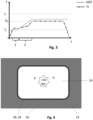
- Fig. 3 is a graph showing the temperature Ti of the hollow mandrel 16 over the time t and the heat deflection temperature HDT of the hollow mandrel 16.
- the heat deflection temperature HDT is defined as indicated in [6].
- Tg illustrates a first temperature wherein the material of the hollow mandrel 16 can be easily formed.
- Tg is the starting temperature above which a thermo forming of the pressing tool such as the hollow mandrel 16 is possible.
- Tm illustrates a maximum temperature (melting temperature).
- Tc illustrates the curing temperature.
- the temperature Ti is first increased - due to automatic control of the control device 22 - from ambient temperature above the temperature Tg (glass transition temperature) so that the material of the pressing tool - here the hollow mandrel 16 - is amorphous and can be easily formed.
- the pressure p inside the hollow mandrel 16 is increased, and a forming process F starts, in which the hollow mandrel 16 is formed by being blown-up and expanded until the wall of the hollow mandrel 16 presses against the internal surface of the hollow mould 14 (with the still uncured laminate 28 therebetween).
- the hollow mandrel 16 is formed corresponding to the form of the mould 14.
- the end of the forming process F is shown in Fig. 4 .
- the pressure p inside the hollow mandrel 16 is increased to up to 10 bar.
- the temperature Ti is gradually increased while the high pressure p inside the hollow mandrel 16 is maintained.
- the temperature Ti is controlled such that a crystallization process C is conducted wherein the material of the hollow mandrel 16 crystallizes.
- the forming process F is conducted at 110°C.
- this temperature can be maintained after forming for conducting the crystallization process C.
- the temperature Ti is increased for conducting the crystallization process.
- the crystallization time for PET has a minimum at 140°C. Hence, Ti may be raised to such a temperature where crystallization is conducted very quickly.
- the crystallization leads to a massive increase of the heat deflection temperature HDT and of the barrier properties of the hollow mandrel 16.
- the temperature Ti is further increased to the curing temperature Tc.
- Tc curing temperature
- the pressing tool may be provided with a release layer (not shown) at the contact surface contacting the composite material.
- the method comprises:
- the method further comprises:
- the composite part (26) may be hardened, for example by conducting the step: f) curing the composite part (26) between the mould (14) and the crystallized tube mandrel (16).
Landscapes
- Chemical & Material Sciences (AREA)
- Engineering & Computer Science (AREA)
- Composite Materials (AREA)
- Mechanical Engineering (AREA)
- Moulding By Coating Moulds (AREA)
- Casting Or Compression Moulding Of Plastics Or The Like (AREA)
Abstract
Description
- The invention relates to a method and an arrangement for manufacturing a composite part, especially for an aircraft, using a mandrel technology.
- For technical background and prior art, reference is made to the following citations:
- [1]
EP 3 740 364 A1 - [2]
US 2021/ 0 008 765 A1 - [3]
US 9 757 876 B2 - [4]
WO 2021 / 076 777 A1 - [5]
US 2016/ 0 200 009 A1 - [6] Heat deflection temperature - Wikipedia; download from https://en.wikipedia.org/wiki/Heat_deflection_temperature on September 30, 2022
- [7]
DE 10 2008 054 540 A1 - [8]
EP 1 707 344 A1 - [9]
US 2010 151 169 A1 - [10]
DE 10 2013 006 940 B4 - If fibre composite parts with hollow bodies or undercuts are to be produced, so-called mandrel technologies are used. Preferred embodiments of the invention relate to such a mandrel technology. A mandrel (also referred to sometimes as core) fills a cavity or an undercut in the manufacture of fibre composite components, e.g., for preventing resin penetration and for allowing the laminate to be compressed.
- Hollow mandrels (also referred to as tube mandrels) must be able to adapt to the contour they have to fill in order to transfer sufficient pressure to material to be consolidated, e.g., cured, such as laminate, and avoid bridging. They act as a separation layer between resin/laminate and compression medium such as a gas. Industrial applied tube mandrels rely on oversized thermoplastic hoses for this purpose, which enable this adaptation due to compensating folds. Even with compensation folds, bridging in small corner radii is still a problem and a time-consuming draping process is required. Alternatively, hollow mandrels used in conventional processes may also be pre-formed. This draping or preforming processes increase the cost of the related manufacturing processes.
- An object of the invention is to provide a method and an arrangement for manufacturing a composite part using a mould and a pressing tool such as a mandrel with less effort and less costs.
- For achieving such object, the invention provides a method according to
claim 1, and an arrangement according to the further independent claim. - Advantageous embodiments are subject-matters of the dependent claims.
- The invention provides a method for manufacturing a composite part, preferably for an aircraft, the method comprising:
- a) providing a mould;
- b) providing a composite material including fibre material and matrix material on a forming surface of the hollow mould;
- c) providing a pressing tool made of semi-crystalline thermoplastic material in an amorphous state on the forming surface of the mould;
- d) forming the pressing tool by pressing the pressing tool against the composite material on the mould;
- e) conducting a crystallization of the material of the pressing tool formed by step d).
- Preferably, the pressing tool is a separation layer between resin/laminate and compression medium such as a gas.
- An idea underlying the invention is to use a pressing tool made from plastic with a low forming temperature, to adapt the form of the pressing tool to the form of a mould, and then to make the material of the pressing tool stable against higher temperatures by targeted crystallization of the pressing tool material. This idea can be used for different moulding procedures, especially vacuum moulding procedures, during manufacturing of composite material components. According to some embodiments, a flat mould and a pressing tool in form of a foil can be used which is pressed by evacuating the space between the mould and the foil. Especially, the idea can be used for mandrels as pressing tools.
- According to some embodiments, the composite material may comprise a thermoplastic material, wherein the composite component is cooled down after the forming step using the crystallized pressing tool. In most preferred embodiments, the composite material comprises thermos-curable matrix material, and a curing step is conducted after the forming step using the crystallized pressing tool.
- According to a preferred embodiment, the invention provides a method for manufacturing a composite part, preferably for an aircraft, the method comprising:
- a0) providing a hollow mould;
- b0) providing a composite material with fibre material and thermo-curable matrix material inside the hollow mould;
- c0) providing a hollow mandrel made of semi-crystalline thermoplastic material in an amorphous state inside of the hollow mould;
- d0) forming the hollow mandrel by expanding the hollow mandrel, and pressing the mandrel against the mould;
- e0) controlling the temperature of the hollow mandrel over the time so that material of the hollow mandrel is crystallized; and
- f) curing the composite part between the mould and the crystallized hollow mandrel.
- Preferably, steps d) or d0) comprise a thermo-forming process for adapting the pressing tool to the specific shape of the mould and hence the composite part.
- Step e) or e0) could be conducted by increasing the temperature such that the pressing tool material is crystallized. In other embodiments, a temperature suitable for conduction step d) or d0) is just maintained over the time ("waiting") until material is fully crystallized.
- In a specific example, a pressing tool consisting of a skin or foil from PET can be formed at 110°C, and the temperature of 110°C is maintained until the material is crystallized in full. According to another example, steps e) or e0) comprise changing, especially increasing, the temperature of the pressing tool to a temperature where the crystallization is at optimum. For example, for PET, the temperature is set to 140°C where the crystallization time has a minimum.
- Preferably, step a) or a0) comprise providing the mould with a cavity. Preferably, step a) comprises providing the mould with an undercut.
- Preferably, step b) or b0) comprise placing a laminate on a forming surface of the mould, especially inside the hollow mould. Preferably, step b) or b0) comprise providing fibres and a thermo-curable or a thermoplastic resin. Preferably, step b) or b0) comprise providing a prepreg material.
- The pressing tool may have different shapes. Preferably, a hollow mandrel is used as pressing tool. Preferably, step c) or c0) comprise providing a bladder made from the semi-crystalline thermoplastic material. Preferably, step c) or c0) comprise providing a hose made from the semi-crystalline thermoplastic material. Preferably, step c) or c0) comprise providing pressing tool, especially the hollow mandrel, at a first temperature above the glass transition temperature. Preferably, step c) or c0) comprise providing the pressing tool, such as the hollow mandrel, from a semi-crystalline thermoplastic material chosen from the group consisting of polyethelyne (PE), polypropylene (PP), polybutylene terephthalate (PBT), polyethylene terephthalate (PET), polyetheretherketone (PEEK).
- Preferably, step d) or d0) comprise increasing the pressure at a side of the pressing tool facing away from the composite material. Especially the pressure inside the hollow mandrel is increased. Preferably, step d) or d0) comprise pressing the fibre material and matrix material against the mould. Further, a region between the pressing tool and the mould where the composite material is arranged can be evacuated.
- Preferably, step e) or e0) comprise maintaining an increased pressure for pressing the pressing tool against the composite material and the mould, especially an increased pressure inside the hollow mandrel in order to keep the pressing tool pressed against the mould. Preferably, step e) or e0) comprise controlling the temperature such that the pressing tool material is allowed to crystallize before a final curing temperature for curing the composite material is reached. Preferably, step e) or e0) comprise gradually increasing the temperature of the pressing tool such as the hollow mandrel.
- Preferably, step f) comprises increasing the temperature from a temperature during which the crystallization took place to a curing temperature for curing the composite material. Preferably, step f) comprises maintaining the increased pressure, especially inside the hollow mandrel, in order to press the composite material against the mould during curing.
- Preferably, the method comprises further the step
g) removing the pressing tool (e.g., the hollow mandrel). - For removing the pressing tool, the pressing tool may be provided, at the side facing to the composite material, with a release layer in order enhance the possibility to remove the pressing tool by drawing it away from the composite component. Eventually, the pressing tool could also be melted away.
- Preferably, the method further comprises the step
h) removing the (cured or hardened) composite part from the mould. - According to another aspect, the invention provides an arrangement for manufacturing a composite part, preferably for an aircraft, the arrangement comprising a mould; a pressing tool made of semi-crystalline thermoplastic material in an amorphous state configured to be formed by being pressed against a forming surface of the mould; a heating device for heating the pressing tool to a controlled temperature (Ti, Tg, Tc); a pressure supply device for pressing the pressing tool against the forming surface of the mould; and a control device configured to control the heating device and the pressure supply device in order to carry out the method according to any of the preceding embodiments.
- According to a preferred embodiment, an arrangement for manufacturing a composite part, preferably for an aircraft, the arrangement comprises:
- a hollow mould;
- a hollow mandrel made of semi-crystalline thermoplastic material in an amorphous state configured to be formed inside of the hollow mould;
- a heating device for heating the mandrel to a controlled temperature;
- a pressure supply device for providing an increased pressure inside the hollow mandrel; and
- a control device configured to control the heating device and the pressure supply device in order to carry out the method according to any of the preceding embodiments.
- Preferred embodiments of the invention relate to an in situ blow moulded hollow mandrel. Especially, embodiments relate to a method for forming and curing a composite part using a mould and an in-situ blow moulded hollow mandrel. Preferably, the hollow mandrel is formed in the mould and then stabilized, especially by crystallization.
- Embodiments of the invention provide methods for forming composite parts between a mould and a pressing tool, wherein pressing tools neither require a preforming nor a draping process. Especially, semi-cured pressing tools are used.
- Some embodiments of the invention provide a cheap hollow mandrel technology which can be used for curved profiles. Embodiments of the invention provide a cheap hollow mandrel technology for the production of semi cured hollow mandrels.
- The hollow mandrel technology according to preferred embodiments of the invention can be used for curved profiles and does not require neither a preforming nor a draping process.
- A hollow mandrel technology according to embodiments of the invention comprises a blow-moulded hollow mandrel or other pressing tools such as forming foils or other separation layers having other open geometries, which can be formed at low temperatures. Preferably, the pressing tool is suitable to be formed by applying a pressurized medium such that it is pressed against the mould and automatically takes the form needed.
- This means that a preforming process is not necessary, because the forming of the pressing tool such as a mandrel can take place at the beginning of the curing process (or during a forming process) of fibre composite material itself. To achieve this, a semi-crystalline thermoplastic material is used, which is in an amorphous state first. In the amorphous state, thermoplastics have a low heat deflection temperature (see [6] for definition of "heat deflection temperature") and can be easily formed, but are not able to resist to the high curing (e.g. 180°C for typical aerospace grade composite materials) temperatures. However, over time at higher temperatures, the material crystallizes which massively increases its heat deflection temperature and barrier properties. In preferred embodiments, the force for forming is provided by an increased internal pressure which will also pressurize the laminate after the forming process. In preferred embodiments, the curing process is controlled in a way that the hollow mandrel material is allowed to crystallize before the final curing temperature is reached.
- Embodiments of the invention are explained below referring to the accompanying drawings in which:
- Fig. 1
- is a schematic block diagram of an arrangement for manufacturing a composite part, especially a composite part for an aircraft;
- Fig. 2
- is a schematic cross-sectional view of a forming tool and a pressing tool in the form of a hollow mandrel used in the arrangement of
Fig. 1 at the beginning of a forming process for forming the hollow mandrel; - Fig. 3
- is a chart illustrating the temperature Ti inside the forming tool and the heat deflection temperature of the hollow mandrel during a curing process for curing the composite part; and
- Fig. 4
- is a schematic cross-sectional view of the forming tool and the hollow mandrel at the end of a blow moulding process for forming the hollow mandrel.
-
Fig. 1 shows anarrangement 10 for manufacturing a composite part. Thearrangement 10 comprises a formingtool 12 with ahollow mould 14, a pressing tool, here in form of ahollow mandrel 16, aheating device 18, apressure supply device 20, and acontrol device 22. In the situation shown, the formingtool 12 is already provided with composite material for manufacturing acomposite part 26. - In the embodiment shown, the
hollow mould 14 encloses acavity 24 wherein acomposite part 26 can be formed and cured. Therefore, fibre material and matrix material are placed at the inside of themould 14. Thehollow mandrel 16 can be inserted into thecavity 24 and can be expanded in order to press the fibre material and the matrix material against the inner forming surface of themould 14. While amould 14 with acavity 24 is shown, the technology works also with a mould with at least one undercut. Further, the technology also works with moulds and other pressing tools having other shapes. For example, the mould can have an open geometry and the pressing tool may be a foil as a separation layer covering the composite material for conducting a vacuum pressing process. - In some embodiments, a laminate 28 including fibres and matrix material is placed in or on (a forming surface of) the
mould 14. The laminate 28 is configured to be cured at a curing temperature Tc, for example 180° in order to achieve thecomposite part 26.Fig. 1 and 2 show the situation where still no or no significant difference pressure p is applied (p<1bar). - The pressing tool such as the
hollow mandrel 16 is made from semi-crystalline thermoplastic material which is provided in an amorphous state first. Examples for semi-crystalline thermoplastic materials are polyethelyne (PE), polypropylene (PP), polybutylene terephthalate (PBT), polyethylene terephthalate (PET), and polyetheretherketone (PEEK). Thehollow mandrel 16 is formed as a bladder or a hose and includes an inlet for pressurized medium. By increasing an internal pressure p within thehollow mandrel 16, thehollow mandrel 16 can be expanded. Since the material is in the amorphous phase, this expansion can be easily achieved. - The
heating device 18 includes one orseveral heating elements 30 and is controlled by thecontrol device 22. Theheating device 18 is configured to heat thehollow mandrel 16 to a controlled temperature Ti. In some embodiments, theheating device 18 is configured to heat pressure medium to be supplied inside thehollow mandrel 16 to a temperature Ti in accordance with commands from thecontrol device 22. In some embodiments, aheating element 30 is arranged inside thehollow mandrel 16 or inside the formingtool 12 or outside the formingtool 12.Heating elements 30 may be part of an autoclave (not shown) in which the formingtool 12 is placed during the forming, crystallization and curing process. - The
pressure supply device 20 includes a source of pressurized medium such as compressed air. For example, thepressure device 20 includes apump 32. Thepressure supply device 20 is controlled by thecontrol device 22 and is configured to set a predefined pressure p in the interior of thehollow mandrel 16. - Also not shown, the
arrangement 10 comprises a temperature sensor and a pressure sensor connected to thecontrol device 22. Thecontrol device 22 is configured to set and regulate the temperature T within the cavity and the internal pressure p within thehollow mandrel 16 in accordance with a predefined mandrel forming process and composite part curing process. Thecontrol device 22 is preferably an electronic control unit ECU programmed with corresponding software. - In the following a method for manufacturing the
composite part 26 is explained with reference toFigs. 2 to 4 . - As shown in
Fig. 2 , the laminate 28 is placed on the internal surface (example of a forming surface) of thehollow mould 14. Thehollow mandrel 16 is provided with an initial size smaller than the cavity and with the semi-crystalline thermoplastic material in the amorphous state first. Thehollow mandrel 16 is placed inside themould 14 wherein the pressure p within thehollow mandrel 16 is at ambient pressure, e.g., 1 bar. -
Fig. 3 is a graph showing the temperature Ti of thehollow mandrel 16 over the time t and the heat deflection temperature HDT of thehollow mandrel 16. The heat deflection temperature HDT is defined as indicated in [6]. Tg illustrates a first temperature wherein the material of thehollow mandrel 16 can be easily formed. Tg is the starting temperature above which a thermo forming of the pressing tool such as thehollow mandrel 16 is possible. Tm illustrates a maximum temperature (melting temperature). Tc illustrates the curing temperature. - As shown in
Fig. 3 , the temperature Ti is first increased - due to automatic control of the control device 22 - from ambient temperature above the temperature Tg (glass transition temperature) so that the material of the pressing tool - here the hollow mandrel 16 - is amorphous and can be easily formed. The pressure p inside thehollow mandrel 16 is increased, and a forming process F starts, in which thehollow mandrel 16 is formed by being blown-up and expanded until the wall of thehollow mandrel 16 presses against the internal surface of the hollow mould 14 (with the stilluncured laminate 28 therebetween). Thus, thehollow mandrel 16 is formed corresponding to the form of themould 14. The end of the forming process F is shown inFig. 4 . For example, the pressure p inside thehollow mandrel 16 is increased to up to 10 bar. - After the forming process F, the temperature Ti is gradually increased while the high pressure p inside the
hollow mandrel 16 is maintained. The temperature Ti is controlled such that a crystallization process C is conducted wherein the material of thehollow mandrel 16 crystallizes. For example, when using PET as pressing tool material, the forming process F is conducted at 110°C. According to an embodiment not shown, this temperature can be maintained after forming for conducting the crystallization process C. According to the embodiment shown, the temperature Ti is increased for conducting the crystallization process. For example, the crystallization time for PET has a minimum at 140°C. Hence, Ti may be raised to such a temperature where crystallization is conducted very quickly. The crystallization leads to a massive increase of the heat deflection temperature HDT and of the barrier properties of thehollow mandrel 16. - The temperature Ti is further increased to the curing temperature Tc. In this state, the curing of the laminate 28 is conducted, while the laminate is pressed by the formed and crystallized
hollow mandrel 16 against the surface of themould 14. - After curing, the
hollow mandrel 16 is removed, and thecomposite part 16 can be removed from themould 14. For an easier removal, the pressing tool may be provided with a release layer (not shown) at the contact surface contacting the composite material. - An arrangement and a method for manufacturing a composite part (26), preferably for an aircraft, have been described. The method comprises:
- a) providing a mould, especially a hollow mould (14); and
- b) providing a composite material including fibre material and (preferably thermo-curable) matrix material on a forming surface of the mould (14).
- In order to provide a simple and cheap technology for forming and optionally curing the component at the mould (14), the method further comprises:
- c) providing a pressing tool, especially a hollow mandrel (16), made of semi-crystalline thermoplastic material in an amorphous state on the forming surface of the mould (14);
- d) forming the pressing tool, especially by applying a pressure, e.g., by expanding the hollow mandrel (16), and pressing the pressing tool against the mould (14);
- e) conducting crystallization of the pressing tool material, e.g. by increasing the temperature (Ti) of the pressing tool so that material of the pressing tool is crystallized.
- Afterwards, the composite part (26) may be hardened, for example by conducting the step:
f) curing the composite part (26) between the mould (14) and the crystallized tube mandrel (16). -
- 10
- arrangement
- 12
- forming tool
- 14
- mould
- 16
- hollow mandrel
- 18
- heating device
- 20
- pressure supply device
- 22
- control device
- 24
- cavity
- 26
- composite part
- 28
- laminate
- 30
- heating element
- 32
- pump
- F
- forming process
- C
- crystallization process
- p
- pressure inside hollow mandrel
- Ti
- temperature of the hollow mandrel (and inside the hollow mandrel)
- HDT
- heat deflection temperature
- T
- temperature
- t
- time
Claims (12)
- Method for manufacturing a composite part (26), preferably for an aircraft, the method comprising:a) providing a mould (14);b) providing a composite material including fibre material and matrix material on a forming surface of the hollow mould (14);c) providing a pressing tool made of semi-crystalline thermoplastic material in an amorphous state on the forming surface of the mould (14);d) forming the pressing tool by pressing the pressing tool against the forming surface of the mould (14);e) conducting a crystallization of the material of the pressing tool formed by step d).
- Method according to claim 1, characterized in that step a) comprisesa0) providing a hollow mould (14) as pressing tool, wherein step c) comprisesc0) providing a hollow mandrel (16) made of semi-crystalline thermoplastic material in an amorphous state as pressing tool inside the hollow mould, wherein step d) comprisesd0) forming the hollow mandrel (16) by expanding the hollow mandrel (16) and pressing against the mould (14), and wherein step e) comprises:e0) controlling the temperature (Ti) of the hollow mandrel (16) so that the material of the hollow mandrel (16) is crystallized.
- Method according to claim 1 or 2, characterized in that step b) comprisesb0) providing the composite material including fibre material and thermo-curable matrix material on the forming surface of the mould (14); wherein the method further comprises, after step e), the stepf) curing the composite part (26) between the mould (14) and the crystallized pressing tool.
- Method according any of the preceding claims, characterized in that step a) or a0) comprise at least one or several of the steps:a1) providing the mould (14) with a cavity (24);a2) providing the mould with an undercut.
- Method according to any of the preceding claims, characterized in that step b) or b0) comprise at least one or several of the following steps:b1) placing a laminate (28) on the forming surface of the mould (14);b2) providing fibres and a thermo-curable or a thermo-plastic resin;b3) providing a prepreg material.
- Method according to any of the preceding claims, characterized in that step c) or c0) comprise at least one or several of the steps:c1) providing a bladder made from the semi-crystalline thermoplastic material;c2) providing a hose made from the semi-crystalline thermoplastic material;c3) providing the pressing tool at a temperature above the glass transition temperature (Tg) of the thermoplastic material;c4) providing the pressing tool from a semi-crystalline thermoplastic material chosen from the group consisting of polyethelyne (PE), polypropylene (PP), polybutylene terephthalate (PBT), polyethylene terephthalate (PET), polyetheretherketone (PEEK);c5) providing the pressing tool with a skin or foil made from the semi-crystalline thermoplastic material.
- Method according to any of the preceding claims, characterized in that step d) or d0) comprise at least one or several of the following steps:d1) increasing the pressure (p) at the side of the pressing tool facing away from the composite material, especially increasing the pressure at the inside the hollow mandrel (16);d2) pressing the fibre material and matrix material against the mould (14);d3) evacuating a region between the forming surface of the mould (14) and the pressing tool wherein the composite material to be formed is arranged.
- Method according to any of the preceding claims, characterized in that step e) or e0) comprise at least one or several of the following steps:e1) increasing the temperature (Ti) of the pressing tool, especially of the hollow mandrel (16), so that material of the pressing tool is crystallized;e2) keep the pressing tool pressed against the mould (14) with the composite material sandwiched therebetween;e3) maintaining an increased pressure (p) inside the hollow mandrel (16) in order to keep the hollow mandrel (16) pressed against the mould (14);e4) controlling the temperature (Ti) such that the pressing tool material is allowed to crystallize before a final curing temperature (Tc) for curing the composite material is reached;e5) gradually increasing the temperature (Ti) of the pressing tool, especially the hollow mandrel (16).
- Method according to claim 3 or according claim 3 and any of the claims 4 to 8, characterized in that step f) comprises at least one or several of the following steps:f1) increasing the temperature (Ti) from a temperature during which the crystallization of the pressing tool material took place to a curing temperature (Tc) for curing the composite material;f2) maintaining the increased pressure (p) inside the hollow mandrel (16) in order to press the composite material against the mould during curing.
- Method according to any of the preceding claims, characterized by at least one of the further steps:g) removing the pressing tool, especially the hollow mandrel (16);h) removing the cured composite part (26) from the mould.
- Arrangement (10) for manufacturing a composite part (26), preferably for an aircraft, the arrangement comprising:a mould (14);a pressing tool made of semi-crystalline thermoplastic material in an amorphous state configured to be formed by being pressed against a forming surface of the mould (14);a heating device (18) for heating the pressing tool to a controlled temperature (Ti, Tg, Tc);a pressure supply device (20) for pressing the pressing tool against the forming surface of the mould (14); anda control device (22) configured to control the heating device (18) and the pressure supply device (20) in order to carry out the method according to any of the preceding claims.
- Arrangement according to claim 11, characterized in that
the mould (14) is a hollow mould having at least a cavity or undercut and in that the pressing tool is a hollow mandrel (16) for inserting into the hollow mould.
Priority Applications (2)
| Application Number | Priority Date | Filing Date | Title |
|---|---|---|---|
| EP22201271.8A EP4353459A1 (en) | 2022-10-13 | 2022-10-13 | Method and arrangement for manufacturing a composite part |
| US18/379,294 US20240227325A9 (en) | 2022-10-13 | 2023-10-12 | Method and arrangement for manufacturing a composite part |
Applications Claiming Priority (1)
| Application Number | Priority Date | Filing Date | Title |
|---|---|---|---|
| EP22201271.8A EP4353459A1 (en) | 2022-10-13 | 2022-10-13 | Method and arrangement for manufacturing a composite part |
Publications (1)
| Publication Number | Publication Date |
|---|---|
| EP4353459A1 true EP4353459A1 (en) | 2024-04-17 |
Family
ID=83691426
Family Applications (1)
| Application Number | Title | Priority Date | Filing Date |
|---|---|---|---|
| EP22201271.8A Pending EP4353459A1 (en) | 2022-10-13 | 2022-10-13 | Method and arrangement for manufacturing a composite part |
Country Status (2)
| Country | Link |
|---|---|
| US (1) | US20240227325A9 (en) |
| EP (1) | EP4353459A1 (en) |
Citations (4)
| Publication number | Priority date | Publication date | Assignee | Title |
|---|---|---|---|---|
| US20110254189A1 (en) * | 2008-10-10 | 2011-10-20 | Eirecomposites Teoranta | Heated mould for moulding polymeric composites |
| US8800953B2 (en) * | 2008-12-10 | 2014-08-12 | The Boeing Company | Method for Producing Composite Laminates Using a Collapsible Mandrel |
| US9120246B2 (en) * | 2013-03-01 | 2015-09-01 | Bell Helicopter Textron Inc. | Pressure tunable expandable mandrel for manufacturing a composite structure |
| US9238335B2 (en) * | 2008-07-10 | 2016-01-19 | The Boeing Company | Mandrel for autoclave curing applications |
Family Cites Families (2)
| Publication number | Priority date | Publication date | Assignee | Title |
|---|---|---|---|---|
| US20130154154A1 (en) * | 2011-06-27 | 2013-06-20 | William L. Rodman | Composite structures having cored members |
| CN110753728B (en) * | 2017-06-15 | 2023-05-09 | 阿科玛股份有限公司 | Production of semi-crystalline parts from pseudo-amorphous polymers |
-
2022
- 2022-10-13 EP EP22201271.8A patent/EP4353459A1/en active Pending
-
2023
- 2023-10-12 US US18/379,294 patent/US20240227325A9/en active Pending
Patent Citations (4)
| Publication number | Priority date | Publication date | Assignee | Title |
|---|---|---|---|---|
| US9238335B2 (en) * | 2008-07-10 | 2016-01-19 | The Boeing Company | Mandrel for autoclave curing applications |
| US20110254189A1 (en) * | 2008-10-10 | 2011-10-20 | Eirecomposites Teoranta | Heated mould for moulding polymeric composites |
| US8800953B2 (en) * | 2008-12-10 | 2014-08-12 | The Boeing Company | Method for Producing Composite Laminates Using a Collapsible Mandrel |
| US9120246B2 (en) * | 2013-03-01 | 2015-09-01 | Bell Helicopter Textron Inc. | Pressure tunable expandable mandrel for manufacturing a composite structure |
Non-Patent Citations (1)
| Title |
|---|
| HEAT DEFLECTION TEMPERATURE, 30 September 2022 (2022-09-30), Retrieved from the Internet <URL:https://en.wikipedia.org/wiki/Heat_deflection_temperature> |
Also Published As
| Publication number | Publication date |
|---|---|
| US20240227325A9 (en) | 2024-07-11 |
| US20240131809A1 (en) | 2024-04-25 |
Similar Documents
| Publication | Publication Date | Title |
|---|---|---|
| EP3006180B1 (en) | Method and device for manufacturing fiber-reinforced plastic | |
| CA2662476C (en) | Forming-molding tool and process for producing preforms and fiber reinforced plastics with the tool | |
| US9321217B2 (en) | Thermal processing and consolidation system and method | |
| CN102821933B (en) | Method for producing an SMC multi-layer component | |
| US7854874B2 (en) | Apparatus and methods for forming hat stiffened composite parts using thermally expansive tooling cauls | |
| EP2236262B1 (en) | Method of molding fiber-reinforced-resin hollow part | |
| CN114269548A (en) | Method and device for producing a component made of a fiber composite material | |
| US5534218A (en) | Process for the production of a hollow body of thermoplastic material | |
| EP3932644B1 (en) | Systems and methods for producing parts at elevated temperatures | |
| US20240227325A9 (en) | Method and arrangement for manufacturing a composite part | |
| JP6784728B2 (en) | Heat treatment and solidification system and its method | |
| JP2009097725A5 (en) | ||
| EP3274145B1 (en) | Processes for manufacturing parts employing additive manufacturing | |
| WO2014202953A1 (en) | Methods for composite material processing | |
| SE509250C2 (en) | Arrangement and method for forming load-taking elements of reinforced thermoplastics, and such a load-taking element | |
| EP1838518B1 (en) | Process for making swaged lighting holes in planar areas of preimpregnated composite parts | |
| US11628632B2 (en) | Pre-consolidated charges of chopped fiber for composite part fabrication | |
| JP6796280B2 (en) | Method for manufacturing fiber-reinforced thermoplastic resin molded product | |
| US20210308963A1 (en) | Method for manufacturing a bagged preform of a component made of composite material and method for manufacturing said component | |
| JP6990595B2 (en) | Fuel tank molding method | |
| CN112810108A (en) | Method for manufacturing plastic box | |
| EP4714643A1 (en) | Method for joining at least two components and stiffened component manufactured thereby | |
| US20140167322A1 (en) | System and method for molding elastomer parts using a temperature-activated pressure applicator | |
| CN117400564A (en) | Methods of manufacturing composite parts, mandrels and methods of manufacturing disposable mandrels | |
| JP2012196861A (en) | Method for manufacturing hollow fiber reinforced plastic |
Legal Events
| Date | Code | Title | Description |
|---|---|---|---|
| PUAI | Public reference made under article 153(3) epc to a published international application that has entered the european phase |
Free format text: ORIGINAL CODE: 0009012 |
|
| STAA | Information on the status of an ep patent application or granted ep patent |
Free format text: STATUS: THE APPLICATION HAS BEEN PUBLISHED |
|
| AK | Designated contracting states |
Kind code of ref document: A1 Designated state(s): AL AT BE BG CH CY CZ DE DK EE ES FI FR GB GR HR HU IE IS IT LI LT LU LV MC ME MK MT NL NO PL PT RO RS SE SI SK SM TR |
|
| STAA | Information on the status of an ep patent application or granted ep patent |
Free format text: STATUS: REQUEST FOR EXAMINATION WAS MADE |
|
| 17P | Request for examination filed |
Effective date: 20241017 |
|
| RBV | Designated contracting states (corrected) |
Designated state(s): AL AT BE BG CH CY CZ DE DK EE ES FI FR GB GR HR HU IE IS IT LI LT LU LV MC ME MK MT NL NO PL PT RO RS SE SI SK SM TR |