EP4353414A1 - Electric tool and control method therefor - Google Patents
Electric tool and control method therefor Download PDFInfo
- Publication number
- EP4353414A1 EP4353414A1 EP22806856.5A EP22806856A EP4353414A1 EP 4353414 A1 EP4353414 A1 EP 4353414A1 EP 22806856 A EP22806856 A EP 22806856A EP 4353414 A1 EP4353414 A1 EP 4353414A1
- Authority
- EP
- European Patent Office
- Prior art keywords
- rotational speed
- brushless motor
- target rotational
- controller
- motor
- Prior art date
- Legal status (The legal status is an assumption and is not a legal conclusion. Google has not performed a legal analysis and makes no representation as to the accuracy of the status listed.)
- Pending
Links
Images




Classifications
-
- H—ELECTRICITY
- H02—GENERATION; CONVERSION OR DISTRIBUTION OF ELECTRIC POWER
- H02P—CONTROL OR REGULATION OF ELECTRIC MOTORS, ELECTRIC GENERATORS OR DYNAMO-ELECTRIC CONVERTERS; CONTROLLING TRANSFORMERS, REACTORS OR CHOKE COILS
- H02P6/00—Arrangements for controlling synchronous motors or other dynamo-electric motors using electronic commutation dependent on the rotor position; Electronic commutators therefor
- H02P6/14—Electronic commutators
- H02P6/15—Controlling commutation time
- H02P6/153—Controlling commutation time wherein the commutation is advanced from position signals phase in function of the speed
-
- B—PERFORMING OPERATIONS; TRANSPORTING
- B25—HAND TOOLS; PORTABLE POWER-DRIVEN TOOLS; MANIPULATORS
- B25B—TOOLS OR BENCH DEVICES NOT OTHERWISE PROVIDED FOR, FOR FASTENING, CONNECTING, DISENGAGING, OR HOLDING
- B25B23/00—Details of, or accessories for, spanners, wrenches, screwdrivers
- B25B23/14—Arrangement of torque limiters or torque indicators in wrenches or screwdrivers
- B25B23/147—Arrangement of torque limiters or torque indicators in wrenches or screwdrivers specially adapted for electrically operated wrenches or screwdrivers
- B25B23/1475—Arrangement of torque limiters or torque indicators in wrenches or screwdrivers specially adapted for electrically operated wrenches or screwdrivers for impact wrenches or screwdrivers
-
- B—PERFORMING OPERATIONS; TRANSPORTING
- B25—HAND TOOLS; PORTABLE POWER-DRIVEN TOOLS; MANIPULATORS
- B25B—TOOLS OR BENCH DEVICES NOT OTHERWISE PROVIDED FOR, FOR FASTENING, CONNECTING, DISENGAGING, OR HOLDING
- B25B21/00—Portable power-driven screw or nut setting or loosening tools; Attachments for drilling apparatus serving the same purpose
- B25B21/02—Portable power-driven screw or nut setting or loosening tools; Attachments for drilling apparatus serving the same purpose with means for imparting impact to screwdriver blade or nut socket
-
- H—ELECTRICITY
- H02—GENERATION; CONVERSION OR DISTRIBUTION OF ELECTRIC POWER
- H02P—CONTROL OR REGULATION OF ELECTRIC MOTORS, ELECTRIC GENERATORS OR DYNAMO-ELECTRIC CONVERTERS; CONTROLLING TRANSFORMERS, REACTORS OR CHOKE COILS
- H02P27/00—Arrangements or methods for the control of AC motors characterised by the kind of supply voltage
- H02P27/04—Arrangements or methods for the control of AC motors characterised by the kind of supply voltage using variable-frequency supply voltage, e.g. inverter or converter supply voltage
- H02P27/06—Arrangements or methods for the control of AC motors characterised by the kind of supply voltage using variable-frequency supply voltage, e.g. inverter or converter supply voltage using DC to AC converters or inverters
- H02P27/08—Arrangements or methods for the control of AC motors characterised by the kind of supply voltage using variable-frequency supply voltage, e.g. inverter or converter supply voltage using DC to AC converters or inverters with pulse width modulation
- H02P27/085—Arrangements or methods for the control of AC motors characterised by the kind of supply voltage using variable-frequency supply voltage, e.g. inverter or converter supply voltage using DC to AC converters or inverters with pulse width modulation wherein the PWM mode is adapted on the running conditions of the motor, e.g. the switching frequency
-
- H—ELECTRICITY
- H02—GENERATION; CONVERSION OR DISTRIBUTION OF ELECTRIC POWER
- H02P—CONTROL OR REGULATION OF ELECTRIC MOTORS, ELECTRIC GENERATORS OR DYNAMO-ELECTRIC CONVERTERS; CONTROLLING TRANSFORMERS, REACTORS OR CHOKE COILS
- H02P6/00—Arrangements for controlling synchronous motors or other dynamo-electric motors using electronic commutation dependent on the rotor position; Electronic commutators therefor
- H02P6/08—Arrangements for controlling the speed or torque of a single motor
-
- H—ELECTRICITY
- H02—GENERATION; CONVERSION OR DISTRIBUTION OF ELECTRIC POWER
- H02P—CONTROL OR REGULATION OF ELECTRIC MOTORS, ELECTRIC GENERATORS OR DYNAMO-ELECTRIC CONVERTERS; CONTROLLING TRANSFORMERS, REACTORS OR CHOKE COILS
- H02P6/00—Arrangements for controlling synchronous motors or other dynamo-electric motors using electronic commutation dependent on the rotor position; Electronic commutators therefor
- H02P6/14—Electronic commutators
- H02P6/16—Circuit arrangements for detecting position
- H02P6/17—Circuit arrangements for detecting position and for generating speed information
-
- H—ELECTRICITY
- H02—GENERATION; CONVERSION OR DISTRIBUTION OF ELECTRIC POWER
- H02P—CONTROL OR REGULATION OF ELECTRIC MOTORS, ELECTRIC GENERATORS OR DYNAMO-ELECTRIC CONVERTERS; CONTROLLING TRANSFORMERS, REACTORS OR CHOKE COILS
- H02P2205/00—Indexing scheme relating to controlling arrangements characterised by the control loops
- H02P2205/07—Speed loop, i.e. comparison of the motor speed with a speed reference
Definitions
- the present invention relates to the control field, and in particular, to a power tool and a control method thereof.
- the power tool may be powered by a battery pack. After a switch of the power tool is switched on to supply power, a motor rotates and drives a transmission mechanism to achieve various power operations.
- PWM pulse-width modulation
- an objective of the present invention is to provide a power tool and a control method thereof.
- the power tool can satisfy a desire of an output power for a user.
- the present application provides a power tool, comprising:
- the controller adjusts a pulse-width modulation (PWM) duty cycle and/or a conduction angle of the switch component, so that the brushless motor maintains the first target rotational speed or the second target rotational speed.
- PWM pulse-width modulation
- the controller is further configured to adjust an advance angle of the switch component.
- the brushless motor is a three-phase brushless motor
- the brushless motor comprises a position sensor
- the controller is configured to calculate an actual motor rotational speed based on a signal transmitted by the position sensor, a conduction angle of each phase in the three-phase brushless motor has a minimum value of 120° and a maximum value of 180°.
- the conduction angle is adjusted by a fixed increment slope, and the increment is any value from 0.1° to 0.5°.
- the power tool is an impact fastening tool, wherein the impact fastening tool comprises an impact mechanism, and when the parameter is greater than or equal to the set threshold, the impact mechanism performs an impact action.
- the present application further provides a method for controlling a power tool, comprising the following steps:
- the controlling, by the controller, the brushless motor to maintain the first target rotational speed, or the controlling, by the controller, the brushless motor to maintain the second target rotational speed comprises: calculating, by the controller, an actual motor rotational speed of the brushless motor, and increasing, by the controller when the actual motor rotational speed is less than the first target rotational speed or the actual motor rotational speed is less than the second target rotational speed, a PWM duty cycle and/or a conduction angle for driving the brushless motor, wherein an adjustment priority of the PWM duty cycle is higher than that of the conduction angle.
- the controlling, by the controller, the brushless motor to maintain the first target rotational speed, or the controlling, by the controller, the brushless motor to maintain the second target rotational speed comprises: calculating, by the controller, an actual motor rotational speed of the brushless motor, and decreasing, by the controller when the actual motor rotational speed is greater than the first target rotational speed or the actual motor rotational speed is greater than the second target rotational speed, a conduction angle and/or a PWM duty cycle for driving the brushless motor, wherein an adjustment priority of the conduction angle is higher than that of the PWM duty cycle.
- the controller is further configured to adjust an advance angle for driving the brushless motor.
- the present application further provides a power tool, comprising:
- the controller adjusts a PWM duty cycle and/or a conduction angle of the switch component, so that the brushless motor maintains the target rotational speed.
- decreasing the conduction angle and/or the PWM duty cycle of the switch component when the parameter is greater than or equal to the set threshold and an actual motor rotational speed is greater than the second target rotational speed, wherein an adjustment priority of the conduction angle is higher than that of the PWM duty cycle.
- the present application further provides a power tool control method, comprising the following steps:
- the controlling, by the controller, the brushless motor to maintain the target rotational speed comprises: calculating, by the controller, an actual motor rotational speed of the brushless motor, and increasing, by the controller when the actual motor rotational speed is less than the target rotational speed, a PWM duty cycle and/or a conduction angle for driving the brushless motor, wherein an adjustment priority of the PWM duty cycle is higher than that of the conduction angle.
- the controlling, by the controller, the brushless motor to maintain the target rotational speed comprises: calculating, by the controller, an actual motor rotational speed of the brushless motor, and decreasing, by the controller when the actual motor rotational speed is greater than the target rotational speed, the conduction angle and/or the PWM duty cycle for driving the brushless motor, wherein an adjustment priority of the conduction angle is higher than that of the PWM duty cycle.
- a motor rotational speed of the power tool is controlled to maintain a lower second target rotational speed, so that the power tool is prevented from being damaged due to large fluctuations in the motor rotational speed under a heavy load.
- the motor rotational speed of the power tool is controlled to maintain a higher first target rotational speed, so that working efficiency of the power tool is improved before entering a heavy load state.
- embodiments of the present invention further provide a power tool and a control method thereof.
- FIG. 1 is a schematic structural diagram of an impact fastening tool according to a first embodiment of the present invention. It should be understood that, the embodiments of the present invention may also be applied to another fastening tool, grinding tool, cutting tool, cleaning tool, garden tool, and the like.
- the impact fastening tool 100 includes: a housing 101, a motor 102, an output end 103, a controller 104, an impact mechanism 106, and a battery pack 105.
- the motor 102 is disposed in an upper cavity of the housing 101 and includes a rotor and a stator.
- the motor 102 is a three-phase brushless direct current (BLDC) motor and is powered by the battery pack 105 under control of the controller 104.
- the motor may also use another form of motor. This is not limited herein.
- a trigger switch 107 may be disposed on a handle of the housing 101 for providing user input to the controller 104, so that the controller 104 controls an operation of the impact fastening tool 100 based on instructions input by the user.
- the trigger switch 107 may be a trigger switch based on a displacement sensor, or may be another form of switch, such as switches based on a touch sensor, a capacitive sensor, and the like.
- the controller 104 may be disposed in a cavity at a lower part of the handle, and the controller 104 may include a central processing unit (CPU) or another form of processing unit having data processing capabilities and/or instruction execution capabilities.
- CPU central processing unit
- the battery pack 105 may be detachably disposed on the housing 101, or may be disposed in the housing 101 in a built-in mode, or may even be connected to an external power cord, so that the impact fastening tool 100 and the battery pack 105 are connected at a certain length.
- the impact fastening tool of this embodiment uses the battery pack as a power supply unit, it should be understood that the impact fastening tool may also use a conventional alternating current power supply as the power supply unit.
- the impact mechanism 106 includes a tripping unit mainly formed by a hammer and an anvil.
- a workload of the output end 103 increases to a certain extent, the hammer and anvil rotate from one body to a relative rotation with an impact action, so that the hammer repeatedly exerts impact forces in a radial direction of the anvil, that is a tripping state.
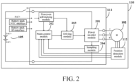
- FIG. 2 is a circuit block diagram of a control system 110 for an impact fastening tool according to this embodiment.
- the control system 110 includes a motor control circuit 111, a battery pack 105, a motor 102, and a position detection module 112.
- the position detection module 112 is generally disposed in the motor, and is configured to detect position information of a rotor on the motor 102 and transmit the position information to the controller.
- the position detection module 112 uses a Hall sensor, or may also use another type of position sensor such as a magneto electric sensor and a photoelectric sensor.
- a main control module 202 receives a position signal from the position detection module 112 and calculates an actual motor rotational speed of the motor 102 based on the position signal.
- a motor with the position detection module used in this embodiment can have a larger conduction angle and advance angle adjustment range.
- a motor coil is an inductive load
- a current in the coil has a certain delay relative to an on load voltage on the coil.
- setting of the advance angle is used to improve this problem.
- the setting of the advance angle is implemented by adjusting an installation position of the Hall sensor.
- a program may also be embedded in control software to set a fixed or variable advance angle, and an effect is similar to that of this embodiment.
- the motor control circuit 111 is configured to drive and control the motor 102.
- the motor control circuit 111 includes a power inverter module 201, a main control module 202, a driving module 203, and a sampling module 204.
- the sampling module 204 is configured to collect a workload parameter of the motor 102 and send the parameter to the controller 104, so that the controller 104 determines an operational status based on the parameter.
- FIG. 3A is a schematic diagram of a power inverter module 201 according to this embodiment.
- the power inverter module 201 is a three-phase bridge inverter circuit, and includes six switch components.
- the six switch components are divided into upper bridge arms and lower bridge arms.
- the six switch components include three upper-side switches and three lower-side switches, which are driven by high driving signals UH, VH and WH and low driving signals UL, VL and WL respectively.
- a source of the upper-side switch of each phase is connected to a drain of the lower-side switch to output a power signal for driving the motor 102.
- the main control module 202 determines a switch frequency and phase commutation timing of the switch components in the power inverter module 201 based on a signal feedback, thereby controlling a rotational speed of the motor 102.
- a conventional constant speed power tool adjusts a motor rotational speed by adjusting a pulse-width modulation (PWM) duty cycle.
- PWM pulse-width modulation
- the duty cycle during the conduction time of each phase conduction angle determines voltage duration supplied to the motor.
- the actual motor rotational speed of the motor may be calculated based on the position information measured by the position detection module. When the actual motor rotational speed is lower than the target rotational speed, the motor rotational speed is increased by increasing the PWM duty cycle.
- FIG. 3B is a driving sequence diagram of a power inverter module 201 when the PWM duty cycle of the three-phase brushless motor is 100%, the conduction angle of each phase is an initial value of 120°, and the advance angle is 0°. It can be seen that between two adjacent phases (such as U phase and V phase), the conduction time of the conduction angle does not overlap.
- the conduction angle is increased, so that the conduction angles of two adjacent phases partially overlap during commutation, which helps to increase a total voltage provided to the motor, thereby further increasing the motor rotational speed.
- an adjustment of the PWM duty cycle is prioritized over an adjustment of the conduction angle; or when the actual motor rotational speed is larger than the target rotational speed and the motor rotational speed needs to be decreased, an adjustment of the conduction angle is prioritized over an adjustment of the PWM duty cycle.
- Priority refers to adjust a variable with a high priority first, and then adjust a variable with a low priority after the variable reaches a maximum value or a minimum value. For example, in a case that the actual motor rotational speed is less than the target rotational speed, priority is given to increasing the PWM duty cycle to increase the motor rotational speed.
- the conduction angle is increased.
- the priority is given to decreasing the conduction angle to decrease the motor rotational speed.
- the conduction angle is decreased to the initial value, there is still a need to decrease speed, and then the PWM duty cycle is decreased.
- the combination of the two adjustment modes greatly broadens an adjustment range of the motor rotational speed and improves flexibility of the motor rotational speed adjustment. It should be understood that the adjustment of the advance angle may also be added on the basis of above to further improve amplitude and flexibility of the rotational speed adjustment.
- a maximum value of the PWM duty cycle is set to 100%, or a maximum value of the PWM duty cycle may also be set to 95% or another in the software program.
- the initial value and the maximum value of the conduction angle basically depend on parameters of the motor itself. In this embodiment, the initial value of the conduction angle of the three-phase brushless direct current motor is 120°, the maximum value is 180°, the initial value of the advance angle is 0°, and the maximum value is 60°.
- the conduction angle when the conduction angle is adjusted, it is preferable to use a fixed increment slope for adjustment, and the increment ranges from 0.1° to 0.5°.
- the motor rotational speed adjustment when an increment value is 0.1°, the motor rotational speed adjustment is more stable.
- it may be considered to use a floating increment slope for adjustment. For example, when it is determined that a difference between the actual motor rotational speed and the target rotational speed is less than a preset threshold, a smaller increment slope for adjustment is used, and when the difference between the actual motor rotational speed and the target rotational speed is greater than or equal to the preset threshold, a larger increment slope for adjustment is used.
- the conduction angle may be maintained at 180° instead of continuing to increase the conduction angle, so as to avoid a decrease in working efficiency of the motor.
- the power tool generally needs a higher rotational speed, it is preferable to use advance commutation to increase the conduction angle, which is beneficial to increasing the rotational speed at medium to high speeds.
- advance commutation may also be used to increase the conduction angle.
- the conduction angle may also be adjusted by combining advance commutation and hysteresis commutation.
- a current flowing through the motor 102 As an example. When a current flowing through the motor collected by the sampling module 204 is less than a set threshold, it is determined that the motor is in a first operational status, and the main control module 202 controls the motor 102 to maintain a first target rotational speed by adjusting the PWM duty cycle and/or the conduction angle. When the current is greater than or equal to the set threshold, it is determined that the motor 102 is in a second operational status, and the main control module 202 controls the motor 102 to maintain a second target rotational speed by adjusting the PWM duty cycle and/or the conduction angle.
- the parameters indicating a load of the motor may also be a vibration of the motor, a force on a working head, a rotational speed of the motor, and another parameter that can represent a size of the load.
- the parameters indicating a load of the motor may also be a vibration of the motor, a force on a working head, a rotational speed of the motor, and another parameter that can represent a size of the load.
- more than two parameters may be used to indicate the load of the motor.
- a current threshold is any value from 10A to 20A, and more preferably, a threshold is 15A.
- the first operational status may refer to the impact fastening tool being in no load or light load state, for example, the impact mechanism 106 does not perform an impact fastening action; and the second operational status may refer to the impact fastening tool being in a heavy load state, for example, the impact mechanism 106 performs an impact fastening action.
- the first target rotational speed is greater than the second target rotational speed.
- the motor rotational speed of the impact fastening tool is controlled to maintain a lower second target rotational speed in the second operational status, so that the impact fastening tool is prevented from being damaged due to large fluctuations in the motor rotational speed under a heavy load.
- the motor rotational speed of the impact fastening tool is controlled to maintain the first target rotational speed that is higher than the second target rotational speed, so that working efficiency of the impact fastening tool is improved before the motor enters a heavy load state.
- the first target rotational speed is any value from 21,850 to 24,150 RPM (r/min).
- the first target rotational speed is 23,000 RPM.
- the second target rotational speed is any value from 12,350 to 13,650 RPM.
- the second target rotational speed is 13,000 RPM. It should be understood that both the first target rotational speed and the second target rotational speed may be set to range values.
- the first target rotational speed and the second target rotational speed may be factory default built-in parameters of the impact fastening tool, or may be set by a user through hardware or software.
- the impact fastening tool may receive the first target rotational speed and the second target rotational speed selected by the user through a functional panel (not shown) provided on the housing 101 of the impact fastening tool.
- the first target rotational speed and the second target rotational speed may have different values based on different user requirements or technical parameters of impact fastening tools with different powers.
- the numerical values mentioned in this embodiment are only examples and are not limited in this embodiment.
- the trigger switch may be arranged, for example, before a displacement reaches 70%, to increase the speed by linearly increasing the PWM duty cycle.
- a program for detecting the load parameter and determining the operational status is started. For example, after the trigger switch is pressed to 70%, the motor rotational speed reaches 23,000 RPM.
- the motor is subject to steady speed control in the second operational status to maintain the motor rotational speed at 13,000 RPM, as shown in FIG. 5 .
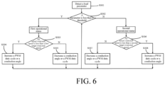
- FIG. 6 is a schematic flowchart of a control method according to this embodiment.
- Step S301 Detect a parameter indicating a workload of a motor.
- Step S302 Determine whether it is in a first operational status or a second operational status based on the parameter.
- Step S303 When it is determined that the parameter is in the first operational status in which the parameter is less than a threshold, it is determined whether an actual motor rotational speed calculated by a controller is less than a first target rotational speed.
- Step S304 When it is determined that the actual motor rotational speed is less than the first target rotational speed, the motor rotational speed is increased by increasing a PWM duty cycle or a conduction angle.
- Step S305 When it is determined that the actual motor rotational speed is not less than the first target rotational speed, the motor rotational speed is decreased by decreasing the conduction angle or the PWM duty cycle.
- Step S306 When it is determined that the parameter is in the second operational status in which the parameter is not less than the threshold, it is determined whether the actual motor rotational speed calculated by the controller is less than a second target rotational speed.
- Step S307 When it is determined that the actual motor rotational speed is not less than the second target rotational speed, the motor rotational speed is decreased by decreasing the conduction angle or the PWM duty cycle.
- Step S308 When it is determined that the actual motor rotational speed is less than the second target rotational speed, the motor rotational speed is increased by increasing the PWM duty cycle or the conduction angle.
- a series of controls are executed repeatedly from S301 to S308, so that the PWM duty cycle and/or the conduction angle for driving the motor is controlled, and finally the motor rotational speed is maintained at the first target rotational speed or the second target rotational speed.
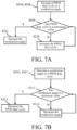
- FIG. 7A is a specific process of increasing the PWM duty cycle or the conduction angle in the foregoing S304 and S308 processes.
- the steps are as follows: Step S309: Determine whether a current PWM duty cycle is a maximum value.
- Step S310 When it is determined that the PWM duty cycle is not the maximum value, the PWM duty cycle is increased.
- Step S311 When it is determined that the PWM duty cycle is the maximum value, the conduction angle is increased.
- FIG. 7B is a specific process of decreasing the conduction angle or the PWM duty cycle in the foregoing S305 and S307 processes.
- the steps are as follows: Step S312: Determine whether a current conduction angle is a minimum value.
- Step S313 When it is determined that the current conduction angle is the minimum value, the PWM duty cycle is decreased.
- Step S314 When it is determined that the current conduction angle is not the minimum value, the conduction angle is decreased.
- This embodiment has the same structure as the impact fastening tool of Embodiment 1, and a control scheme of the motor rotational speed is the same when the motor is in a second state. Details are not described herein again.
- the difference from the first embodiment is that when the motor is in the first operational status, this embodiment uses an open-loop control mode to control the motor.
- the open-loop control mode uses a mode of linearly adjusting the PWM duty cycle and/or the conduction angle based on the displacement of the trigger switch.
- the displacement of the trigger switch changes from 0% to 100%
- the PWM duty cycle also changes linearly from 0% to 100%.
- the conduction angle always maintains the initial value.
- the trigger switch changes from 0% to 70%
- the PWM duty cycle changes linearly from 0% to 100%
- the trigger switch changes from 70% to 100%
- the conduction angle increases from the initial value to the specified value.
- the specified value may be a factory default built-in parameter, or may be set by the user based on rotational speed requirements.
- the open-loop control mode is used, and the motor is set based on a program.
- a running speed of the motor at no load is a maximum rotational speed of the motor in the open-loop control mode.
- the motor rotational speed of the impact fastening tool is controlled to maintain a second target rotational speed in the second operational status, so that the impact fastening tool is prevented from being damaged due to large fluctuations in the motor rotational speed under a heavy load.
- the open-loop control mode is used to control the motor rotational, so that the user can control the motor rotational speed based on actual requirements of the impact fastening tool in the first operational status.
- the second target rotational speed is less than a maximum motor rotational speed in the open-loop control mode.
- selecting open-loop control cannot only optimize and control the program, but also reduce power loss in the first operational status.
- FIG. 7 is a schematic flowchart of a control method according to this embodiment.
- Step S401 Detect a parameter indicating a load of a motor.
- Step S402 Determine whether it is in a first operational status or a second operational status based on the parameter.
- Step S403 When it is determined to be in the first operational status, open-loop control is used.
- Step S404 When it is determined to be in the second operational status, it is determined based on the actual motor rotational speed whether it is less than the second target rotational speed.
- Step S405 When it is determined that the actual motor rotational speed is less than the second target rotational speed, the motor rotational speed is increased by increasing a PWM duty cycle or a conduction angle.
- Step S406 When it is determined that the actual motor rotational speed is not less than the second target rotational speed, the motor rotational speed is decreased by decreasing the conduction angle or the PWM duty cycle.
- a series of controls are executed repeatedly from S401 to S406, so that the PWM duty cycle and/or the conduction angle for driving the motor is controlled, and finally the motor rotational speed is maintained at the second target rotational speed or the motor is controlled in an open-loop.
- modes of increasing the PWM duty cycle or the conduction angle and decreasing the conduction angle or the PWM duty cycle are consistent with the processes shown in FIG. 7A and FIG. 7B . Details are not described herein.
Landscapes
- Engineering & Computer Science (AREA)
- Power Engineering (AREA)
- Mechanical Engineering (AREA)
- Control Of Motors That Do Not Use Commutators (AREA)
Abstract
Description
- This application claims priority to
Chinese Patent Application No. 202110528366.6, filed with the China National Intellectual Property Administration on May 14, 2021 - The present invention relates to the control field, and in particular, to a power tool and a control method thereof.
- Power tools have been widely used in homes, gardens, and other operation environments, and bring great convenience to people's life and work. The power tool may be powered by a battery pack. After a switch of the power tool is switched on to supply power, a motor rotates and drives a transmission mechanism to achieve various power operations.
- In ordinary power tools, adjustment of a pulse-width modulation (PWM) duty cycle in an open-loop or closed-loop mode is generally used to achieve an expected output power. However, the adjustment of the PWM duty cycle alone cannot meet a requirement for obtaining a higher or more stable output power.
- The present invention aims to resolve at least one of the technical problems in the prior art. Therefore, an objective of the present invention is to provide a power tool and a control method thereof. The power tool can satisfy a desire of an output power for a user.
- The present application provides a power tool, comprising:
- a power supply unit;
- a brushless motor, comprising a stator and a rotor;
- an inverter circuit, comprising a plurality of switch components, wherein the plurality of switch components are configured to perform a switch action to control driving of the brushless motor; and
- a controller, electrically connected to the inverter circuit and the brushless motor, the controller comprising a load detection module configured to detect a parameter indicating a workload of the brushless motor,
- wherein when the parameter is less than a set threshold, the controller controls the brushless motor to maintain a first target rotational speed;
- when the parameter is greater than or equal to the set threshold, the controller controls the brushless motor to maintain a second target rotational speed; and
- the first target rotational speed is greater than the second target rotational speed.
- In one of the embodiments, the controller adjusts a pulse-width modulation (PWM) duty cycle and/or a conduction angle of the switch component, so that the brushless motor maintains the first target rotational speed or the second target rotational speed.
- In one of the embodiments, the controller is further configured to adjust an advance angle of the switch component.
- In one of the embodiments, increasing the PWM duty cycle and/or the conduction angle of the switch component when the parameter is less than the set threshold and an actual motor rotational speed is less than the first target rotational speed or when the parameter is greater than or equal to the set threshold and an actual motor rotational speed is less than the second target rotational speed, wherein an adjustment priority of the PWM duty cycle is higher than that of the conduction angle.
- In one of the embodiments, decreasing the PWM duty cycle and/or the conduction angle of the switch component when the parameter is less than the set threshold and an actual motor rotational speed is greater than the first target rotational speed or when the parameter is greater than or equal to the set threshold and an actual motor rotational speed is greater than the second target rotational speed, wherein an adjustment priority of the conduction angle is higher than that of the PWM duty cycle.
- In one of the embodiments, the brushless motor is a three-phase brushless motor, the brushless motor comprises a position sensor, the controller is configured to calculate an actual motor rotational speed based on a signal transmitted by the position sensor, a conduction angle of each phase in the three-phase brushless motor has a minimum value of 120° and a maximum value of 180°.
- In one of the embodiments, the conduction angle is adjusted by a fixed increment slope, and the increment is any value from 0.1° to 0.5°.
- In one of the embodiments, the power tool is an impact fastening tool, wherein the impact fastening tool comprises an impact mechanism, and when the parameter is greater than or equal to the set threshold, the impact mechanism performs an impact action.
- The present application further provides a method for controlling a power tool, comprising the following steps:
- detecting, by a controller, a parameter indicating a workload of a brushless motor, and determining an operational status of the power tool based on the parameter;
- controlling, by the controller when determining that the parameter is less than a set threshold, the brushless motor to maintain a first target rotational speed;
- controlling, by the controller when determining that the parameter is greater than or equal to the set threshold, the brushless motor to maintain a second target rotational speed; and
- the first target rotational speed is greater than the second target rotational speed.
- In one of the embodiments, the controlling, by the controller, the brushless motor to maintain the first target rotational speed, or the controlling, by the controller, the brushless motor to maintain the second target rotational speed comprises: calculating, by the controller, an actual motor rotational speed of the brushless motor, and increasing, by the controller when the actual motor rotational speed is less than the first target rotational speed or the actual motor rotational speed is less than the second target rotational speed, a PWM duty cycle and/or a conduction angle for driving the brushless motor, wherein an adjustment priority of the PWM duty cycle is higher than that of the conduction angle.
- In one of the embodiments, the controlling, by the controller, the brushless motor to maintain the first target rotational speed, or the controlling, by the controller, the brushless motor to maintain the second target rotational speed comprises: calculating, by the controller, an actual motor rotational speed of the brushless motor, and decreasing, by the controller when the actual motor rotational speed is greater than the first target rotational speed or the actual motor rotational speed is greater than the second target rotational speed, a conduction angle and/or a PWM duty cycle for driving the brushless motor, wherein an adjustment priority of the conduction angle is higher than that of the PWM duty cycle.
- In one of the embodiments, the controller is further configured to adjust an advance angle for driving the brushless motor.
- The present application further provides a power tool, comprising:
- a power supply unit;
- a brushless motor, comprising a stator and a rotor;
- an inverter circuit, comprising a plurality of switch components, wherein the plurality of switch components are configured to perform a switch action to control driving of the brushless motor; and
- a controller, electrically connected to the inverter circuit and the brushless motor, the controller comprising a load detection module configured to detect a parameter indicating a workload of the brushless motor,
- wherein when the parameter is greater than or equal to a set threshold, the controller controls the brushless motor to maintain a target rotational speed;
- when the parameter is less than a set threshold, the controller controls the brushless motor in an open-loop mode, and the brushless motor has a maximum rotational speed under the control in the open-loop mode; and
- the maximum rotational speed under the control in the open-loop mode is greater than the target rotational speed.
- In one of the embodiments, the controller adjusts a PWM duty cycle and/or a conduction angle of the switch component, so that the brushless motor maintains the target rotational speed.
- In one of the embodiments, increasing the PWM duty cycle and/or the conduction angle of the switch component when the parameter is greater than or equal to the set threshold and an actual motor rotational speed is less than the target rotational speed, wherein an adjustment priority of the PWM duty cycle is higher than that of the conduction angle.
- In one of the embodiments, decreasing the conduction angle and/or the PWM duty cycle of the switch component, when the parameter is greater than or equal to the set threshold and an actual motor rotational speed is greater than the second target rotational speed, wherein an adjustment priority of the conduction angle is higher than that of the PWM duty cycle.
- The present application further provides a power tool control method, comprising the following steps:
- detecting, by a controller, a parameter indicating a workload of a brushless motor, and determining an operational status of the power tool based on the parameter;
- controlling, when it is determined that the parameter is less than a set threshold, the brushless motor in an open-loop mode, and the brushless motor has a maximum rotational speed under the control in the open-loop mode;
- controlling, by the controller when determining that the parameter is greater than or equal to a set threshold, the brushless motor to maintain a target rotational speed; and
- the maximum rotational speed in the open-loop mode is greater than the target rotational speed.
- In one of the embodiments, the controlling, by the controller, the brushless motor to maintain the target rotational speed comprises: calculating, by the controller, an actual motor rotational speed of the brushless motor, and increasing, by the controller when the actual motor rotational speed is less than the target rotational speed, a PWM duty cycle and/or a conduction angle for driving the brushless motor, wherein an adjustment priority of the PWM duty cycle is higher than that of the conduction angle.
- In one of the embodiments, the controlling, by the controller, the brushless motor to maintain the target rotational speed comprises: calculating, by the controller, an actual motor rotational speed of the brushless motor, and decreasing, by the controller when the actual motor rotational speed is greater than the target rotational speed, the conduction angle and/or the PWM duty cycle for driving the brushless motor, wherein an adjustment priority of the conduction angle is higher than that of the PWM duty cycle.
- According to the present invention, a motor rotational speed of the power tool is controlled to maintain a lower second target rotational speed, so that the power tool is prevented from being damaged due to large fluctuations in the motor rotational speed under a heavy load. The motor rotational speed of the power tool is controlled to maintain a higher first target rotational speed, so that working efficiency of the power tool is improved before entering a heavy load state.
- To describe the technical solutions in the embodiments of the present invention more clearly, the following briefly introduces the accompanying drawings required for describing the embodiments. Apparently, the accompanying drawings in the following description show merely some embodiments of the present invention, and a person of ordinary skill in the art may still derive other drawings from these accompanying drawings without creative efforts.
-
FIG. 1 is a schematic structural diagram of an impact fastening tool according to Embodiment 1 of the present invention; -
FIG. 2 is a circuit block diagram of a control system for an impact fastening tool according to Embodiment 1 of the present invention; -
FIG. 3A is a schematic diagram of a power inverter module according to Embodiment 1 of the present invention; -
FIG. 3B is a driving sequence diagram of an initial conduction angle according to Embodiment 1 of the present invention; -
FIG. 4 is a driving sequence diagram for increasing a conduction angle according to Embodiment 1 of the present invention; -
FIG. 5 is a curve of a relationship between a trigger switch run length and motor control according to Embodiment 1 of the present invention; -
FIG. 6 is a schematic flowchart of a control method according to Embodiment 1 of the present invention; -
FIG. 7A is a schematic flowchart of increasing a PWM duty cycle or a conduction angle according to Embodiment 1 of the present invention; -
FIG. 7B is a schematic flowchart of decreasing a conduction angle or a PWM duty cycle according to Embodiment 1 of the present invention; and -
FIG. 8 is a schematic flowchart of a control method according to Embodiment 2 of the present invention. - To resolve the foregoing problem, embodiments of the present invention further provide a power tool and a control method thereof. The following describes the embodiments of the present invention in detail with reference to the accompanying drawings.
- The following clearly and completely describes the technical solutions in the embodiments of the present invention in detail. Apparently, the described embodiments are merely some rather than all of the embodiments of the present invention. Based on the embodiments of the present invention, all other embodiments obtained by a person of ordinary skill in the art without creative efforts shall fall within the protection scope of the present invention.
- It should be noted that, when a component is referred to as "being disposed to" another component, the component may be directly on the another component, or an intermediate component may also be present. When a component is considered to be "connected to" another component, the component may be directly connected to the another component, or an intermediate component may also be present. The terms "vertical", "horizontal", "left", "right", and similar expressions used in this specification are merely used for purposes of illustration but not indicate a unique implementation.
- Unless otherwise defined, meanings of all technical and scientific terms used in this specification are the same as those usually understood by a person skilled in the art to which the present invention belongs. In this specification, terms used in this specification of the present invention are merely intended to describe objectives of the specific embodiments, but are not intended to limit the present invention.
-
FIG. 1 is a schematic structural diagram of an impact fastening tool according to a first embodiment of the present invention. It should be understood that, the embodiments of the present invention may also be applied to another fastening tool, grinding tool, cutting tool, cleaning tool, garden tool, and the like. - The
impact fastening tool 100 includes: ahousing 101, amotor 102, anoutput end 103, acontroller 104, animpact mechanism 106, and abattery pack 105. - The
motor 102 is disposed in an upper cavity of thehousing 101 and includes a rotor and a stator. In this embodiment, themotor 102 is a three-phase brushless direct current (BLDC) motor and is powered by thebattery pack 105 under control of thecontroller 104. The motor may also use another form of motor. This is not limited herein. - A
trigger switch 107 may be disposed on a handle of thehousing 101 for providing user input to thecontroller 104, so that thecontroller 104 controls an operation of theimpact fastening tool 100 based on instructions input by the user. Thetrigger switch 107 may be a trigger switch based on a displacement sensor, or may be another form of switch, such as switches based on a touch sensor, a capacitive sensor, and the like. - The
controller 104 may be disposed in a cavity at a lower part of the handle, and thecontroller 104 may include a central processing unit (CPU) or another form of processing unit having data processing capabilities and/or instruction execution capabilities. - The
battery pack 105 may be detachably disposed on thehousing 101, or may be disposed in thehousing 101 in a built-in mode, or may even be connected to an external power cord, so that theimpact fastening tool 100 and thebattery pack 105 are connected at a certain length. Although the impact fastening tool of this embodiment uses the battery pack as a power supply unit, it should be understood that the impact fastening tool may also use a conventional alternating current power supply as the power supply unit. - The
impact mechanism 106 includes a tripping unit mainly formed by a hammer and an anvil. When a workload of theoutput end 103 increases to a certain extent, the hammer and anvil rotate from one body to a relative rotation with an impact action, so that the hammer repeatedly exerts impact forces in a radial direction of the anvil, that is a tripping state. -
FIG. 2 is a circuit block diagram of acontrol system 110 for an impact fastening tool according to this embodiment. Thecontrol system 110 includes amotor control circuit 111, abattery pack 105, amotor 102, and aposition detection module 112. Theposition detection module 112 is generally disposed in the motor, and is configured to detect position information of a rotor on themotor 102 and transmit the position information to the controller. In this embodiment, theposition detection module 112 uses a Hall sensor, or may also use another type of position sensor such as a magneto electric sensor and a photoelectric sensor. Amain control module 202 receives a position signal from theposition detection module 112 and calculates an actual motor rotational speed of themotor 102 based on the position signal. Compared with a motor without the position detection module, a motor with the position detection module used in this embodiment can have a larger conduction angle and advance angle adjustment range. - Because a motor coil is an inductive load, a current in the coil has a certain delay relative to an on load voltage on the coil. Generally, setting of the advance angle is used to improve this problem. In this embodiment, the setting of the advance angle is implemented by adjusting an installation position of the Hall sensor. As a transformation, a program may also be embedded in control software to set a fixed or variable advance angle, and an effect is similar to that of this embodiment.
- The
motor control circuit 111 is configured to drive and control themotor 102. Themotor control circuit 111 includes apower inverter module 201, amain control module 202, adriving module 203, and asampling module 204. - The
sampling module 204 is configured to collect a workload parameter of themotor 102 and send the parameter to thecontroller 104, so that thecontroller 104 determines an operational status based on the parameter. -
FIG. 3A is a schematic diagram of apower inverter module 201 according to this embodiment. Thepower inverter module 201 is a three-phase bridge inverter circuit, and includes six switch components. The six switch components are divided into upper bridge arms and lower bridge arms. The six switch components include three upper-side switches and three lower-side switches, which are driven by high driving signals UH, VH and WH and low driving signals UL, VL and WL respectively. A source of the upper-side switch of each phase is connected to a drain of the lower-side switch to output a power signal for driving themotor 102. Themain control module 202 determines a switch frequency and phase commutation timing of the switch components in thepower inverter module 201 based on a signal feedback, thereby controlling a rotational speed of themotor 102. - A conventional constant speed power tool adjusts a motor rotational speed by adjusting a pulse-width modulation (PWM) duty cycle. The duty cycle during the conduction time of each phase conduction angle determines voltage duration supplied to the motor. Generally, the greater the duty cycle, the longer the voltage duration supplied to the motor during the conduction time, and the greater the motor rotational speed. The actual motor rotational speed of the motor may be calculated based on the position information measured by the position detection module. When the actual motor rotational speed is lower than the target rotational speed, the motor rotational speed is increased by increasing the PWM duty cycle. However, when the PWM duty cycle increases to a maximum value of 100%, in a case that the actual motor rotational speed has not reached the target rotational speed, and because voltage duration cannot be continued to increase during conduction time, the motor rotational speed cannot be increased by increasing the PWM duty cycle, which causes the power tool to fail to achieve an expected output.
-
FIG. 3B is a driving sequence diagram of apower inverter module 201 when the PWM duty cycle of the three-phase brushless motor is 100%, the conduction angle of each phase is an initial value of 120°, and the advance angle is 0°. It can be seen that between two adjacent phases (such as U phase and V phase), the conduction time of the conduction angle does not overlap. In this embodiment, to further increase the rotational speed of the power tool to achieve the expected output, as shown inFIG. 4 , the conduction angle is increased, so that the conduction angles of two adjacent phases partially overlap during commutation, which helps to increase a total voltage provided to the motor, thereby further increasing the motor rotational speed. - Specifically, when the actual motor rotational speed is less than the target rotational speed and the motor rotational speed needs to be increased, an adjustment of the PWM duty cycle is prioritized over an adjustment of the conduction angle; or when the actual motor rotational speed is larger than the target rotational speed and the motor rotational speed needs to be decreased, an adjustment of the conduction angle is prioritized over an adjustment of the PWM duty cycle. Priority refers to adjust a variable with a high priority first, and then adjust a variable with a low priority after the variable reaches a maximum value or a minimum value. For example, in a case that the actual motor rotational speed is less than the target rotational speed, priority is given to increasing the PWM duty cycle to increase the motor rotational speed. When the PWM duty cycle reaches the maximum value, in a case that there is still a need to increase speed, then the conduction angle is increased. In a case that the actual motor rotational speed is greater than the target rotational speed and the conduction angle is greater than the initial value, the priority is given to decreasing the conduction angle to decrease the motor rotational speed. When the conduction angle is decreased to the initial value, there is still a need to decrease speed, and then the PWM duty cycle is decreased. The combination of the two adjustment modes greatly broadens an adjustment range of the motor rotational speed and improves flexibility of the motor rotational speed adjustment. It should be understood that the adjustment of the advance angle may also be added on the basis of above to further improve amplitude and flexibility of the rotational speed adjustment.
- In this embodiment, a maximum value of the PWM duty cycle is set to 100%, or a maximum value of the PWM duty cycle may also be set to 95% or another in the software program. The initial value and the maximum value of the conduction angle basically depend on parameters of the motor itself. In this embodiment, the initial value of the conduction angle of the three-phase brushless direct current motor is 120°, the maximum value is 180°, the initial value of the advance angle is 0°, and the maximum value is 60°.
- Specifically, when the conduction angle is adjusted, it is preferable to use a fixed increment slope for adjustment, and the increment ranges from 0.1° to 0.5°. Preferably, when an increment value is 0.1°, the motor rotational speed adjustment is more stable. In addition, it may be considered to use a floating increment slope for adjustment. For example, when it is determined that a difference between the actual motor rotational speed and the target rotational speed is less than a preset threshold, a smaller increment slope for adjustment is used, and when the difference between the actual motor rotational speed and the target rotational speed is greater than or equal to the preset threshold, a larger increment slope for adjustment is used. In a case that the conduction angle reaches 180° but the actual motor rotational speed still cannot reach the target rotational speed, the conduction angle may be maintained at 180° instead of continuing to increase the conduction angle, so as to avoid a decrease in working efficiency of the motor.
- Since the power tool generally needs a higher rotational speed, it is preferable to use advance commutation to increase the conduction angle, which is beneficial to increasing the rotational speed at medium to high speeds. However, it should be understood that, based on specific working conditions and power of the power tool, hysteresis commutation may also be used to increase the conduction angle. Furthermore, the conduction angle may also be adjusted by combining advance commutation and hysteresis commutation.
- Using a current flowing through the
motor 102 as an example. When a current flowing through the motor collected by thesampling module 204 is less than a set threshold, it is determined that the motor is in a first operational status, and themain control module 202 controls themotor 102 to maintain a first target rotational speed by adjusting the PWM duty cycle and/or the conduction angle. When the current is greater than or equal to the set threshold, it is determined that themotor 102 is in a second operational status, and themain control module 202 controls themotor 102 to maintain a second target rotational speed by adjusting the PWM duty cycle and/or the conduction angle. However, it should be clear that the parameters indicating a load of the motor may also be a vibration of the motor, a force on a working head, a rotational speed of the motor, and another parameter that can represent a size of the load. For accuracy, more than two parameters may be used to indicate the load of the motor. - Preferably, a current threshold is any value from 10A to 20A, and more preferably, a threshold is 15A. The first operational status may refer to the impact fastening tool being in no load or light load state, for example, the
impact mechanism 106 does not perform an impact fastening action; and the second operational status may refer to the impact fastening tool being in a heavy load state, for example, theimpact mechanism 106 performs an impact fastening action. - In this embodiment, the first target rotational speed is greater than the second target rotational speed. The motor rotational speed of the impact fastening tool is controlled to maintain a lower second target rotational speed in the second operational status, so that the impact fastening tool is prevented from being damaged due to large fluctuations in the motor rotational speed under a heavy load. In addition, in the first operational status, the motor rotational speed of the impact fastening tool is controlled to maintain the first target rotational speed that is higher than the second target rotational speed, so that working efficiency of the impact fastening tool is improved before the motor enters a heavy load state.
- Specifically, the first target rotational speed is any value from 21,850 to 24,150 RPM (r/min). Preferably, the first target rotational speed is 23,000 RPM. The second target rotational speed is any value from 12,350 to 13,650 RPM. Preferably, the second target rotational speed is 13,000 RPM. It should be understood that both the first target rotational speed and the second target rotational speed may be set to range values.
- The first target rotational speed and the second target rotational speed may be factory default built-in parameters of the impact fastening tool, or may be set by a user through hardware or software. For example, the impact fastening tool may receive the first target rotational speed and the second target rotational speed selected by the user through a functional panel (not shown) provided on the
housing 101 of the impact fastening tool. The first target rotational speed and the second target rotational speed may have different values based on different user requirements or technical parameters of impact fastening tools with different powers. The numerical values mentioned in this embodiment are only examples and are not limited in this embodiment. - Since a value of the first target rotational speed is relatively high, to stabilize the speed increase during a startup phase, the trigger switch may be arranged, for example, before a displacement reaches 70%, to increase the speed by linearly increasing the PWM duty cycle. After the trigger switch reaches 70%, a program for detecting the load parameter and determining the operational status is started. For example, after the trigger switch is pressed to 70%, the motor rotational speed reaches 23,000 RPM. When it is detected that the load parameter is greater than the set threshold, according to this embodiment, the motor is subject to steady speed control in the second operational status to maintain the motor rotational speed at 13,000 RPM, as shown in
FIG. 5 . -
FIG. 6 is a schematic flowchart of a control method according to this embodiment. - Step S301: Detect a parameter indicating a workload of a motor.
- Step S302: Determine whether it is in a first operational status or a second operational status based on the parameter.
- Step S303: When it is determined that the parameter is in the first operational status in which the parameter is less than a threshold, it is determined whether an actual motor rotational speed calculated by a controller is less than a first target rotational speed.
- Step S304: When it is determined that the actual motor rotational speed is less than the first target rotational speed, the motor rotational speed is increased by increasing a PWM duty cycle or a conduction angle.
- Step S305: When it is determined that the actual motor rotational speed is not less than the first target rotational speed, the motor rotational speed is decreased by decreasing the conduction angle or the PWM duty cycle.
- Step S306: When it is determined that the parameter is in the second operational status in which the parameter is not less than the threshold, it is determined whether the actual motor rotational speed calculated by the controller is less than a second target rotational speed.
- Step S307: When it is determined that the actual motor rotational speed is not less than the second target rotational speed, the motor rotational speed is decreased by decreasing the conduction angle or the PWM duty cycle.
- Step S308: When it is determined that the actual motor rotational speed is less than the second target rotational speed, the motor rotational speed is increased by increasing the PWM duty cycle or the conduction angle.
- A series of controls are executed repeatedly from S301 to S308, so that the PWM duty cycle and/or the conduction angle for driving the motor is controlled, and finally the motor rotational speed is maintained at the first target rotational speed or the second target rotational speed.
- Specifically,
FIG. 7A is a specific process of increasing the PWM duty cycle or the conduction angle in the foregoing S304 and S308 processes. When it is determined that the PWM duty cycle or the conduction angle needs to be increased, the steps are as follows:
Step S309: Determine whether a current PWM duty cycle is a maximum value. - Step S310: When it is determined that the PWM duty cycle is not the maximum value, the PWM duty cycle is increased.
- Step S311: When it is determined that the PWM duty cycle is the maximum value, the conduction angle is increased.
- The foregoing series of controls are executed repeatedly from S309 to S311, when the PWM duty cycle or the conduction angle needs to be increased, an adjustment of the PWM duty cycle is prioritized over an adjustment of the conduction angle.
- Specifically,
FIG. 7B is a specific process of decreasing the conduction angle or the PWM duty cycle in the foregoing S305 and S307 processes. When it is determined that the conduction angle or the PWM duty cycle needs to be decreased, the steps are as follows:
Step S312: Determine whether a current conduction angle is a minimum value. - Step S313: When it is determined that the current conduction angle is the minimum value, the PWM duty cycle is decreased.
- Step S314: When it is determined that the current conduction angle is not the minimum value, the conduction angle is decreased.
- The foregoing series of controls are executed repeatedly from S312 to S314, when the conduction angle or the PWM duty cycle needs to be decreased, the adjustment of the conduction angle is prioritized over the adjustment of the PWM duty cycle.
- This embodiment has the same structure as the impact fastening tool of Embodiment 1, and a control scheme of the motor rotational speed is the same when the motor is in a second state. Details are not described herein again. The difference from the first embodiment is that when the motor is in the first operational status, this embodiment uses an open-loop control mode to control the motor.
- Specifically, the open-loop control mode uses a mode of linearly adjusting the PWM duty cycle and/or the conduction angle based on the displacement of the trigger switch. For example, the displacement of the trigger switch changes from 0% to 100%, and the PWM duty cycle also changes linearly from 0% to 100%. During this process, the conduction angle always maintains the initial value. For another example, the trigger switch changes from 0% to 70%, the PWM duty cycle changes linearly from 0% to 100%, the trigger switch changes from 70% to 100%, and the conduction angle increases from the initial value to the specified value. The specified value may be a factory default built-in parameter, or may be set by the user based on rotational speed requirements.
- In a first state, the open-loop control mode is used, and the motor is set based on a program. Generally, when the trigger switch is moved to 100%, a running speed of the motor at no load is a maximum rotational speed of the motor in the open-loop control mode.
- The motor rotational speed of the impact fastening tool is controlled to maintain a second target rotational speed in the second operational status, so that the impact fastening tool is prevented from being damaged due to large fluctuations in the motor rotational speed under a heavy load. In the first operational status, the open-loop control mode is used to control the motor rotational, so that the user can control the motor rotational speed based on actual requirements of the impact fastening tool in the first operational status. The second target rotational speed is less than a maximum motor rotational speed in the open-loop control mode.
- In this embodiment, in the first operational status, selecting open-loop control cannot only optimize and control the program, but also reduce power loss in the first operational status.
-
FIG. 7 is a schematic flowchart of a control method according to this embodiment. - Step S401: Detect a parameter indicating a load of a motor.
- Step S402: Determine whether it is in a first operational status or a second operational status based on the parameter.
- Step S403: When it is determined to be in the first operational status, open-loop control is used.
- Step S404: When it is determined to be in the second operational status, it is determined based on the actual motor rotational speed whether it is less than the second target rotational speed.
- Step S405: When it is determined that the actual motor rotational speed is less than the second target rotational speed, the motor rotational speed is increased by increasing a PWM duty cycle or a conduction angle.
- Step S406: When it is determined that the actual motor rotational speed is not less than the second target rotational speed, the motor rotational speed is decreased by decreasing the conduction angle or the PWM duty cycle.
- A series of controls are executed repeatedly from S401 to S406, so that the PWM duty cycle and/or the conduction angle for driving the motor is controlled, and finally the motor rotational speed is maintained at the second target rotational speed or the motor is controlled in an open-loop.
- In this embodiment, modes of increasing the PWM duty cycle or the conduction angle and decreasing the conduction angle or the PWM duty cycle are consistent with the processes shown in
FIG. 7A and FIG. 7B . Details are not described herein. - In addition, it should be further noted that, the combination of technical features in the disclosure is not limited to the combination described in the claims of the disclosure or the combination described in the specific embodiments. All technical features described in the disclosure may be freely combined or combined in any way, unless there is a conflict between each other.
- It should be noted that the foregoing examples are merely specific embodiments of the present invention. Obviously, the present invention is not limited to the foregoing embodiments, and there are many similar changes. All modifications directly derived or thought of by a person skilled in the art from the disclosure of the present invention shall fall within the protection scope of the present invention.
- It should be understood that the first, second, and other qualifiers mentioned in the embodiments of the present invention are merely used to describe the technical solutions of the embodiments of the present invention more clearly and cannot be used to limit the protection scope of the present invention.
- The foregoing descriptions are merely preferred embodiments of the present invention, are not intended to limit the protection scope of the present invention. A person skilled in the art may make various modifications and changes to this disclosure. Any modification, equivalent replacement, or improvement made without departing from the spirit and principle of this disclosure shall fall within the protection scope of this disclosure.
Claims (19)
- A power tool, comprising:a power supply unit;a brushless motor, comprising a stator and a rotor;an inverter circuit, comprising a plurality of switch components, wherein the plurality of switch components are configured to perform a switch action to control driving of the brushless motor; anda controller, electrically connected to the inverter circuit and the brushless motor, the controller comprising a load detection module configured to detect a parameter indicating a workload of the brushless motor,wherein when the parameter is less than a set threshold, the controller controls the brushless motor to maintain a first target rotational speed;when the parameter is greater than or equal to the set threshold, the controller controls the brushless motor to maintain a second target rotational speed; andthe first target rotational speed is greater than the second target rotational speed.
- The power tool according to claim 1, wherein the controller adjusts a pulse-width modulation (PWM) duty cycle and/or a conduction angle of the switch component, so that the brushless motor maintains the first target rotational speed or the second target rotational speed.
- The power tool according to claim 1, wherein the controller is further configured to adjust an advance angle of the switch component.
- The power tool according to claim 2, wherein increasing the PWM duty cycle and/or the conduction angle of the switch component when the parameter is less than the set threshold and an actual motor rotational speed is less than the first target rotational speed or when the parameter is greater than or equal to the set threshold and an actual motor rotational speed is less than the second target rotational speed, wherein an adjustment priority of the PWM duty cycle is higher than that of the conduction angle.
- The power tool according to claim 2, wherein decreasing the PWM duty cycle and/or the conduction angle of the switch component when the parameter is less than the set threshold and an actual motor rotational speed is greater than the first target rotational speed or when the parameter is greater than or equal to the set threshold and an actual motor rotational speed is greater than the second target rotational speed, wherein an adjustment priority of the conduction angle is higher than that of the PWM duty cycle.
- The power tool according to claim 2, wherein the brushless motor is a three-phase brushless motor, the brushless motor comprises a position sensor, the controller is configured to calculate an actual motor rotational speed based on a signal transmitted by the position sensor, a conduction angle of each phase in the three-phase brushless motor has a minimum value of 120° and a maximum value of 180°.
- The power tool according to claim 4 or 5, wherein the conduction angle is adjusted by a fixed increment slope, and the increment is any value from 0.1° to 0.5°.
- The power tool according to claim 1, wherein the power tool is an impact fastening tool, wherein the impact fastening tool comprises an impact mechanism, and when the parameter is greater than or equal to the set threshold, the impact mechanism performs an impact action.
- A method for controlling a power tool, comprising the following steps:detecting, by a controller, a parameter indicating a workload of a brushless motor, and determining an operational status of the power tool based on the parameter;controlling, by the controller when determining that the parameter is less than a set threshold, the brushless motor to maintain a first target rotational speed;controlling, by the controller when determining that the parameter is greater than or equal to the set threshold, the brushless motor to maintain a second target rotational speed; andthe first target rotational speed is greater than the second target rotational speed.
- The control method according to claim 9, wherein the controlling, by the controller, the brushless motor to maintain the first target rotational speed, or the controlling, by the controller, the brushless motor to maintain the second target rotational speed comprises: calculating, by the controller, an actual motor rotational speed of the brushless motor, and increasing, by the controller when the actual motor rotational speed is less than the first target rotational speed or the actual motor rotational speed is less than the second target rotational speed, a PWM duty cycle and/or a conduction angle for driving the brushless motor, wherein an adjustment priority of the PWM duty cycle is higher than that of the conduction angle.
- The control method according to claim 9, wherein the controlling, by the controller, the brushless motor to maintain the first target rotational speed, or the controlling, by the controller, the brushless motor to maintain the second target rotational speed comprises: calculating, by the controller, an actual motor rotational speed of the brushless motor, and decreasing, by the controller when the actual motor rotational speed is greater than the first target rotational speed or the actual motor rotational speed is greater than the second target rotational speed, a conduction angle and/or a PWM duty cycle for driving the brushless motor, wherein an adjustment priority of the conduction angle is higher than that of the PWM duty cycle.
- The control method according to claim 10 or 11, wherein the controller is further configured to adjust an advance angle for driving the brushless motor.
- A power tool, comprising:a power supply unit;a brushless motor, comprising a stator and a rotor;an inverter circuit, comprising a plurality of switch components, wherein the plurality of switch components are configured to perform a switch action to control driving of the brushless motor; anda controller, electrically connected to the inverter circuit and the brushless motor, the controller comprising a load detection module configured to detect a parameter indicating a workload of the brushless motor,wherein when the parameter is greater than or equal to a set threshold, the controller controls the brushless motor to maintain a target rotational speed;when the parameter is less than a set threshold, the controller controls the brushless motor in an open-loop mode, and the brushless motor has a maximum rotational speed under the control in the open-loop mode; andthe maximum rotational speed under the control in the open-loop mode is greater than the target rotational speed.
- The power tool according to claim 13, wherein the controller adjusts a PWM duty cycle and/or a conduction angle of the switch component, so that the brushless motor maintains the target rotational speed.
- The power tool according to claim 14, wherein increasing the PWM duty cycle and/or the conduction angle of the switch component when the parameter is greater than or equal to the set threshold and an actual motor rotational speed is less than the target rotational speed, wherein an adjustment priority of the PWM duty cycle is higher than that of the conduction angle.
- The power tool according to claim 14, wherein decreasing the conduction angle and/or the PWM duty cycle of the switch component, when the parameter is greater than or equal to the set threshold and an actual motor rotational speed is greater than the second target rotational speed, wherein an adjustment priority of the conduction angle is higher than that of the PWM duty cycle.
- A power tool control method, comprising the following steps:detecting, by a controller, a parameter indicating a workload of a brushless motor, and determining an operational status of the power tool based on the parameter;controlling, when it is determined that the parameter is less than a set threshold, the brushless motor in an open-loop mode, and the brushless motor has a maximum rotational speed under the control in the open-loop mode;controlling, by the controller when determining that the parameter is greater than or equal to a set threshold, the brushless motor to maintain a target rotational speed; andthe maximum rotational speed in the open-loop mode is greater than the target rotational speed.
- The control method according to claim 17, wherein the controlling, by the controller, the brushless motor to maintain the target rotational speed comprises: calculating, by the controller, an actual motor rotational speed of the brushless motor, and increasing, by the controller when the actual motor rotational speed is less than the target rotational speed, a PWM duty cycle and/or a conduction angle for driving the brushless motor, wherein an adjustment priority of the PWM duty cycle is higher than that of the conduction angle.
- The control method according to claim 17, wherein the controlling, by the controller, the brushless motor to maintain the target rotational speed comprises: calculating, by the controller, an actual motor rotational speed of the brushless motor, and decreasing, by the controller when the actual motor rotational speed is greater than the target rotational speed, the conduction angle and/or the PWM duty cycle for driving the brushless motor, wherein an adjustment priority of the conduction angle is higher than that of the PWM duty cycle.
Applications Claiming Priority (2)
| Application Number | Priority Date | Filing Date | Title |
|---|---|---|---|
| CN202110528366 | 2021-05-14 | ||
| PCT/CN2022/092633 WO2022237894A1 (en) | 2021-05-14 | 2022-05-13 | Electric tool and control method therefor |
Publications (2)
| Publication Number | Publication Date |
|---|---|
| EP4353414A1 true EP4353414A1 (en) | 2024-04-17 |
| EP4353414A4 EP4353414A4 (en) | 2025-05-07 |
Family
ID=84028187
Family Applications (1)
| Application Number | Title | Priority Date | Filing Date |
|---|---|---|---|
| EP22806856.5A Pending EP4353414A4 (en) | 2021-05-14 | 2022-05-13 | ELECTRIC TOOL AND ITS CONTROL METHOD |
Country Status (4)
| Country | Link |
|---|---|
| US (1) | US12525903B2 (en) |
| EP (1) | EP4353414A4 (en) |
| CN (1) | CN115768599B (en) |
| WO (1) | WO2022237894A1 (en) |
Family Cites Families (17)
| Publication number | Priority date | Publication date | Assignee | Title |
|---|---|---|---|---|
| US6771043B2 (en) * | 2001-05-09 | 2004-08-03 | Makita Corporation | Power tools |
| JP5182562B2 (en) * | 2008-02-29 | 2013-04-17 | 日立工機株式会社 | Electric tool |
| JP5403328B2 (en) * | 2009-02-02 | 2014-01-29 | 日立工機株式会社 | Electric drilling tool |
| JP5942500B2 (en) * | 2012-03-14 | 2016-06-29 | 日立工機株式会社 | Electric tool |
| CN103684122B (en) * | 2012-09-19 | 2017-05-31 | 比亚迪股份有限公司 | The control method and device of switched reluctance machines |
| JP5960008B2 (en) * | 2012-09-21 | 2016-08-02 | 日立オートモティブシステムズ株式会社 | Brushless motor drive device |
| CN104981325B (en) * | 2013-03-30 | 2018-08-31 | 日立工机株式会社 | Electric tool |
| US10322498B2 (en) * | 2014-10-20 | 2019-06-18 | Makita Corporation | Electric power tool |
| CN106487286A (en) * | 2015-09-02 | 2017-03-08 | 苏州宝时得电动工具有限公司 | A kind of control method of electric tool, device and electric tool |
| WO2017079295A1 (en) * | 2015-11-02 | 2017-05-11 | Black & Decker Inc. | Reducing noise and lowering harmonics in power tools using conduction band control schemes |
| KR101834974B1 (en) * | 2016-10-10 | 2018-03-07 | 계양전기 주식회사 | Control method of electrically-drive tool |
| KR101834970B1 (en) | 2016-12-14 | 2018-03-08 | 한국기계연구원 | Driving device of artificial muscle module and driving method of artificial muscle module |
| JP6901898B2 (en) * | 2017-04-17 | 2021-07-14 | 株式会社マキタ | Rotating striking tool |
| EP4395156B1 (en) * | 2018-02-28 | 2026-04-08 | Milwaukee Electric Tool Corporation | Simulated bog-down system and method for power tools |
| CN110739890B (en) * | 2018-07-02 | 2023-05-09 | 苏州宝时得电动工具有限公司 | Speed control method of electric tool and electric tool |
| CN110880903A (en) * | 2018-09-06 | 2020-03-13 | 米沃奇电动工具公司 | System and method for thermal management using speed control of a power tool |
| JP7386027B2 (en) * | 2019-09-27 | 2023-11-24 | 株式会社マキタ | rotary impact tool |
-
2022
- 2022-05-13 EP EP22806856.5A patent/EP4353414A4/en active Pending
- 2022-05-13 CN CN202280005223.XA patent/CN115768599B/en active Active
- 2022-05-13 WO PCT/CN2022/092633 patent/WO2022237894A1/en not_active Ceased
-
2023
- 2023-11-14 US US18/389,441 patent/US12525903B2/en active Active
Also Published As
| Publication number | Publication date |
|---|---|
| EP4353414A4 (en) | 2025-05-07 |
| US20240088807A1 (en) | 2024-03-14 |
| CN115768599A (en) | 2023-03-07 |
| US12525903B2 (en) | 2026-01-13 |
| CN115768599B (en) | 2026-03-20 |
| WO2022237894A1 (en) | 2022-11-17 |
Similar Documents
| Publication | Publication Date | Title |
|---|---|---|
| EP3235119B1 (en) | Control scheme to increase power output of a power tool using conduction band and advance angle | |
| JP2008508002A (en) | Surgical machine and operating method of surgical machine | |
| EP4173756B1 (en) | Power tool | |
| US12220834B2 (en) | Chain saw | |
| EP3750670B1 (en) | Electric power tool and control method therefor | |
| US12062999B2 (en) | Method for controlling a rotational speed of an electric tool and electric tool | |
| EP3370924A1 (en) | Reducing noise and lowering harmonics in power tools using conduction band control schemes | |
| US12267035B2 (en) | Power tool including conduction angle control | |
| EP3731402A1 (en) | Power tool and control method for the same | |
| US12525903B2 (en) | Power tool and control method thereof | |
| CN118100696A (en) | Electric tool and control method thereof | |
| EP4727003A1 (en) | Power tool and control method thereof | |
| CN120244076B (en) | Power tools and their control methods | |
| CN120262963B (en) | Electric tool and control method thereof | |
| CN104917429B (en) | A kind of brushless electric machine constant flow starting system and method | |
| US12149190B2 (en) | Power tool, impact wrench, and tool control method | |
| US20240297608A1 (en) | Power tool | |
| JP2020179449A (en) | Electric tool | |
| EP4618402A1 (en) | Electric tool and control method therefor | |
| CN120262963A (en) | Electric tool and control method thereof | |
| CN118868680A (en) | Electric tool and brushless motor control method, control module and storage medium | |
| CN106533288A (en) | Frequency conversion energy saving generating set | |
| CN119995468A (en) | Electric tool and control method thereof | |
| CN114629382A (en) | Intelligent electric tool and control method thereof |
Legal Events
| Date | Code | Title | Description |
|---|---|---|---|
| STAA | Information on the status of an ep patent application or granted ep patent |
Free format text: STATUS: THE INTERNATIONAL PUBLICATION HAS BEEN MADE |
|
| PUAI | Public reference made under article 153(3) epc to a published international application that has entered the european phase |
Free format text: ORIGINAL CODE: 0009012 |
|
| STAA | Information on the status of an ep patent application or granted ep patent |
Free format text: STATUS: REQUEST FOR EXAMINATION WAS MADE |
|
| 17P | Request for examination filed |
Effective date: 20231213 |
|
| AK | Designated contracting states |
Kind code of ref document: A1 Designated state(s): AL AT BE BG CH CY CZ DE DK EE ES FI FR GB GR HR HU IE IS IT LI LT LU LV MC MK MT NL NO PL PT RO RS SE SI SK SM TR |
|
| DAV | Request for validation of the european patent (deleted) | ||
| DAX | Request for extension of the european patent (deleted) | ||
| P01 | Opt-out of the competence of the unified patent court (upc) registered |
Free format text: CASE NUMBER: APP_9013/2025 Effective date: 20250221 |
|
| REG | Reference to a national code |
Ref country code: DE Ref legal event code: R079 Free format text: PREVIOUS MAIN CLASS: B25B0021020000 Ipc: H02P0006080000 |
|
| A4 | Supplementary search report drawn up and despatched |
Effective date: 20250409 |
|
| RIC1 | Information provided on ipc code assigned before grant |
Ipc: H02P 27/08 20060101ALI20250403BHEP Ipc: B25B 23/147 20060101ALI20250403BHEP Ipc: B25B 21/02 20060101ALI20250403BHEP Ipc: H02P 6/08 20160101AFI20250403BHEP |