EP4353366A1 - Hot glue gun with temperature setting - Google Patents
Hot glue gun with temperature setting Download PDFInfo
- Publication number
- EP4353366A1 EP4353366A1 EP22201743.6A EP22201743A EP4353366A1 EP 4353366 A1 EP4353366 A1 EP 4353366A1 EP 22201743 A EP22201743 A EP 22201743A EP 4353366 A1 EP4353366 A1 EP 4353366A1
- Authority
- EP
- European Patent Office
- Prior art keywords
- gun
- glue
- heater section
- hot glue
- temperature
- Prior art date
- Legal status (The legal status is an assumption and is not a legal conclusion. Google has not performed a legal analysis and makes no representation as to the accuracy of the status listed.)
- Pending
Links
- 239000004831 Hot glue Substances 0.000 title claims abstract description 37
- 239000003292 glue Substances 0.000 claims abstract description 33
- 239000004836 Glue Stick Substances 0.000 claims abstract description 30
- 238000010438 heat treatment Methods 0.000 claims abstract description 17
- 239000007787 solid Substances 0.000 claims abstract description 10
- 230000000007 visual effect Effects 0.000 claims description 5
- 239000007788 liquid Substances 0.000 description 4
- 238000002844 melting Methods 0.000 description 3
- 230000008018 melting Effects 0.000 description 3
- 230000000295 complement effect Effects 0.000 description 1
- 238000001816 cooling Methods 0.000 description 1
- 230000003247 decreasing effect Effects 0.000 description 1
- 230000001419 dependent effect Effects 0.000 description 1
- 239000000155 melt Substances 0.000 description 1
- 238000000034 method Methods 0.000 description 1
- 230000003287 optical effect Effects 0.000 description 1
Images

Classifications
-
- B—PERFORMING OPERATIONS; TRANSPORTING
- B05—SPRAYING OR ATOMISING IN GENERAL; APPLYING FLUENT MATERIALS TO SURFACES, IN GENERAL
- B05C—APPARATUS FOR APPLYING FLUENT MATERIALS TO SURFACES, IN GENERAL
- B05C17/00—Hand tools or apparatus using hand held tools, for applying liquids or other fluent materials to, for spreading applied liquids or other fluent materials on, or for partially removing applied liquids or other fluent materials from, surfaces
- B05C17/005—Hand tools or apparatus using hand held tools, for applying liquids or other fluent materials to, for spreading applied liquids or other fluent materials on, or for partially removing applied liquids or other fluent materials from, surfaces for discharging material from a reservoir or container located in or on the hand tool through an outlet orifice by pressure without using surface contacting members like pads or brushes
- B05C17/00523—Hand tools or apparatus using hand held tools, for applying liquids or other fluent materials to, for spreading applied liquids or other fluent materials on, or for partially removing applied liquids or other fluent materials from, surfaces for discharging material from a reservoir or container located in or on the hand tool through an outlet orifice by pressure without using surface contacting members like pads or brushes provided with means to heat the material
- B05C17/00526—Hand tools or apparatus using hand held tools, for applying liquids or other fluent materials to, for spreading applied liquids or other fluent materials on, or for partially removing applied liquids or other fluent materials from, surfaces for discharging material from a reservoir or container located in or on the hand tool through an outlet orifice by pressure without using surface contacting members like pads or brushes provided with means to heat the material the material being supplied to the apparatus in a solid state, e.g. rod, and melted before application
Definitions
- the invention relates to a hot glue gun for receiving a solid glue, in particular in the form of a glue stick, for heating the solid glue and for dispensing the glue in a molten state.
- Such a hot glue gun is known from DE 10 2017 105 157 A1 . It comprises a gun housing which forms a handle. For heating the solid glue or the glue stick, the hot glue gun has a heater section with a heating element. The heating element is controlled by a control unit. A control switch can be used to select a first lower temperature and a second higher temperature. This makes it possible to process different glues with the hot glue gun, which have different melting temperatures. For a glue that already melts at lower temperatures, it is sufficient to select the first lower temperature by means of the control switch. The hot glue gun also has a temperature indicator that shows whether the selected temperature has already been reached.
- DE 10 2017 105 157 A1 further discloses a feed device by which the glue stick is fed to the heater section. In this case, the feed device has a lever or trigger on the handle. The user presses this trigger to press the glue stick into the heater section with the aid of the feed device.
- US 6,041,972 also discloses a hot glue gun with a gun housing and a heater section, the heater section being detachably connected to the gun housing. It is thus possible to replace the heater section with the glue stick with another heater section which is also provided with a glue stick. This has the advantage that different glues can be applied with one gun in a short time sequence without significant set-up times.
- US 6,041,972 proposes a heating tray which several heater sections can be coupled simultaneously. When a new heater section is inserted into the gun housing, the hot glue gun is practically immediately ready for use, since the heater section is already heated up.
- glues with a wide range of melting temperatures are to be applied with the gun, it is problematic to select only between a first temperature and a second temperature at which or up to which the respective glue is heated. If, for example, a glue is selected that does not yet melt at the first temperature and whose melting temperature is significantly below the second temperature, the heater section is heated up unnecessarily. In addition, elevated temperatures can reduce the viscosity of the glue to such an extent that controlled dispensing of the liquid glue is difficult.
- the invention is therefore based on the object of providing a hot glue gun through which different glues can be applied in a simple and efficient manner.
- the invention is characterized in that presetting means are provided which are connected to the control unit and by means of which the temperature to which the glue is heated can be individually preset.
- the individually predeterminable temperature can be used to set the desired viscosity of the molten glue, which simplifies the dispensing and application of the liquid glue.
- the temperature can be flexibly adjusted or predetermined depending on the glue.
- the temperature can be continuously preset. This means that any number of values can be specified for the temperature.
- the stepless presetting allows the temperature to be set particularly precisely, by means of which optimum dispensing of the molten glue is made possible.
- a user of the hot glue gun can precisely adjust the viscosity of the molten glue according to his individual needs.
- the presetting means may include a rotatable handwheel, which may also be referred to as a temperature wheel. By turning the handwheel in one direction, the desired temperature can be increased, while by turning it in the opposite direction, the desired temperature can be decreased.
- an axis of rotation of the handwheel coincides with a central axis of the glue stick when the glue stick is inserted in the heater section and when the heater section is connected to the gun housing.
- the handwheel and the inserted glue stick or heater section are coaxially arranged with respect to each other.
- the handwheel is preferably arranged at a rear end of the gun, which faces away from a front end of the gun, at which a dispensing nozzle may be provided.
- the handwheel may have a central opening through which the glue stick extends. Therefore, because of the central opening of the handwheel, glue sticks of any length may be used.
- An interface can be provided between the heater section and the gun housing, which is designed to receive a preset value for the temperature from the heater section and to forward it to the control unit.
- the preset value is thus dependent on the heater section or the glue stick inserted in the heater section.
- the interface can be designed to read an NFC (near field communication) chip that is arranged in the heater section and on which the preset value for the temperature is stored.
- the interface or the further interface is designed to forward a measured temperature value detected in the heater section to the control unit.
- the control unit determines the amount of energy that is supplied to the heater section and in particular to the heating element.
- the preset value stored in the heater section is read in by the control unit and the heater section is heated accordingly.
- the handwheel By turning the handwheel, it is possible for the user of the hot glue gun to readjust the temperature, for example, to slightly increase or reduce the viscosity of the molten glue.
- display means are provided which emit visual or optical signals as a function of the temperature and/or an operating state of the gun.
- the visual signals may differ in terms of color. For example, a rather lower preset value for the temperature may be indicated with the color blue, while a rather higher preset value for the temperature may be indicated with the color orange.
- a flashing (colored) signal can be used to indicate that the preset value for the temperature has not yet been reached.
- a continuous signal can be used to indicate that the preset value for the temperature in the heater section has been reached and that dispensing of the liquid glue can begin.
- the display means may comprise a transparent ring, wherein illuminants may be arranged on an inner circumferential surface of the ring.
- this is a ring with a closed circumference extending over 360°.
- a central axis of the transparent ring may coincide with the central axis of the glue stick when the glue stick is inserted into the heater section and when the heater section is connected to the gun body.
- the ring and the handwheel are arranged coaxially and axially directly adjacent to each other.
- the ring may be disposed at the rear end of the gun.
- the handwheel is the outermost component at that end and the transparent ring is disposed at an axially inner end of the handwheel.
- the transparent ring may be made of a translucent plastic. The surface of the ring can be roughened and/or the plastic can be milky/opaque.
- the illuminating means may comprise a band of LEDs extending along the entire circumference of the inner surface of the ring.
- the ring is illuminated around its entire circumference so that the visual signal is clearly visible from all sides of the gun.
- control unit is housed in an additional housing.
- the additional housing is connected to the gun housing via a cable. Due to the arrangement of the control unit in the additional housing, the weight of the hot glue gun in the narrower sense, i.e. the parts housed in the gun housing including the heater section, is comparatively low, which simplifies handling of the hot glue gun.
- the cable may have a connector that can be detachably connected to a free end of the handle.
- the gun housing and the auxiliary housing are connected via the cable.
- the cable with the plug can be detached from the handle, for example, if the length of the cable is not sufficient for a particular application.
- the gun housing can have a substantially cylindrical receiving space into which the heater section with inserted glue stick can be at least partially pushed along the center axis of the glue stick.
- an outer diameter of a housing part enclosing the receiving space corresponds to an outer diameter of the handwheel and an outer diameter of the transparent ring.
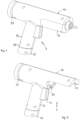
- FIG 1 shows a perspective view of a hot glue gun, denoted in its entirety as 1.
- the hot glue gun 1 comprises a gun housing10 and a heater section 11.
- the gun housing10 forms a handle 12.
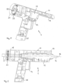
- Figure 2 shows the hot glue gun 1 without the heater section 11. Only the heater section 11 is shown in Figure 3 .
- Figures 4 to 6 show the hot glue gun 1 in various sectional views.
- a glue stick 2 is indicated with a dashed line, which is heated in the heater section 11 so that the solid glue is melted and is present in the liquid state at a dispensing nozzle 13.
- the glue stick 2 can be pressed into the heater section 11 by means of an feed device known in the prior art, of which only a trigger or lever 14 is shown in the figures.
- the glue stick 2 may extend beyond a rear end 15 of the gun body 10.
- the feed device advances the glue stick 2 along its central axis 16 toward the dispensing nozzle 13 or toward a forward end 17 of the gun housing 10.
- the gun housing 10 forms a receiving space 18 into which the heater section 11 can be inserted at least partially along the central axis 16.
- a guide rail 19 is formed on the gun housing 10, in which a complementary guide profile 20 of the heater section 11 (see Figures 3 and 4 ) engages. If the heater section 11 is to be connected to the gun housing 10, the heater section is placed against the gun housing 10 in such a way that the guide profile 20 can be pushed into the guide rail 19 of the gun housing 10 along the center axis 16.
- a handwheel 21 is provided at the rear end 15 of the gun housing 10, which can be rotated about the center axis 16.
- the handwheel 21 is used to preset a temperature at which or up to which the glue is to be heated in the heater section 11.
- the handwheel 21 has a central opening 22 through which the glue stick 2 projects (see Figures 5 and 6 ).
- a circumferential toothing 23 is provided on an inner circumferential surface of the handwheel 21, which interacts with a gear wheel (not shown).
- a rotation of the handwheel 21 thus causes a rotation of the gear wheel, which is connected to a presetting unit (not shown).
- the presetting unit is in turn connected to a control unit (not shown), so that by rotating the handwheel 21 the control unit can be supplied with variable preset values for the temperature in the heater section 11.
- Figure 4 shows a recess 24 in the gun housing 10 into which an interface between the heater section 11 and the gun housing 10 can be inserted.
- This interface is used to supply electrical energy to the heater section 11, which is required by a heating element arranged in the heater section.
- the amount of energy supplied to the heater section is specified by the control unit.
- a plug 26 can be attached to a free or lower end 25 of the handle 12. The connection between the handle 12 and the plug 26 is thereby detachable.
- the plug 26 is in turn connected to a cable (not shown) which leads to the control unit already mentioned above, which is not housed in the gun housing but in an additional housing. Via the cable, electrical energy is supplied to the gun housing 10 or to the heater section 11. Corresponding lines between the connector 26 and the interface, which is located in the recess 24, are not shown in the figures.
- signal lines which are also not shown, exist between the presetting unit for the temperature and the plug 26, as well as signal lines between the plug 26 and the interface, in order to be able to send the measured value of the temperature detected in the heater section 11 to the control unit and to be able to send corresponding control signals to the heating element.
- a transparent ring 27 is arranged between the rear end 15 of the gun housing 10 and the handwheel 21, which is part of a display device with which the preset temperature is visualized in color.
- the transparent ring 27 is illuminated from the inside by an LED strip. Since the transparent ring 27 extends over its entire circumference of 360°, the visual signals of the display device can be easily perceived from any side of the gun.
- the display device is connected to the control unit.
- the hot glue gun 1 is shown without the ring 27.
- the ring 27 is depicted only in Figures 1 and 2 .
Landscapes
- Engineering & Computer Science (AREA)
- Mechanical Engineering (AREA)
- Coating Apparatus (AREA)
Abstract
The invention relates to a hot glue gun (1) for receiving a solid glue, in particular in the form of a glue stick (2), for heating the solid glue and for dispensing the glue in a molten state, the hot glue gun (1) comprising a gun housing (10), which forms a handle (12), a heater section (11) with a heating element for heating the solid glue, the heater section (11) being detachably connected to the gun housing (10), and a control unit by which the heating element is controlled. The invention is characterized in that presetting means are provided which are connected to the control unit and by means of which a temperature to which the glue is heated can be individually preset.
Description
- The invention relates to a hot glue gun for receiving a solid glue, in particular in the form of a glue stick, for heating the solid glue and for dispensing the glue in a molten state.
- Such a hot glue gun is known from
DE 10 2017 105 157 A1 . It comprises a gun housing which forms a handle. For heating the solid glue or the glue stick, the hot glue gun has a heater section with a heating element. The heating element is controlled by a control unit. A control switch can be used to select a first lower temperature and a second higher temperature. This makes it possible to process different glues with the hot glue gun, which have different melting temperatures. For a glue that already melts at lower temperatures, it is sufficient to select the first lower temperature by means of the control switch. The hot glue gun also has a temperature indicator that shows whether the selected temperature has already been reached.DE 10 2017 105 157 A1 further discloses a feed device by which the glue stick is fed to the heater section. In this case, the feed device has a lever or trigger on the handle. The user presses this trigger to press the glue stick into the heater section with the aid of the feed device. -
US 6,041,972 also discloses a hot glue gun with a gun housing and a heater section, the heater section being detachably connected to the gun housing. It is thus possible to replace the heater section with the glue stick with another heater section which is also provided with a glue stick. This has the advantage that different glues can be applied with one gun in a short time sequence without significant set-up times. To prevent a heater section separated from the gun housing from cooling down,US 6,041,972 proposes a heating tray which several heater sections can be coupled simultaneously. When a new heater section is inserted into the gun housing, the hot glue gun is practically immediately ready for use, since the heater section is already heated up. - If glues with a wide range of melting temperatures are to be applied with the gun, it is problematic to select only between a first temperature and a second temperature at which or up to which the respective glue is heated. If, for example, a glue is selected that does not yet melt at the first temperature and whose melting temperature is significantly below the second temperature, the heater section is heated up unnecessarily. In addition, elevated temperatures can reduce the viscosity of the glue to such an extent that controlled dispensing of the liquid glue is difficult.
- The invention is therefore based on the object of providing a hot glue gun through which different glues can be applied in a simple and efficient manner.
- The object underlying the invention is solved with the combination of features of claim 1. Examples of embodiments of the invention can be taken from the subclaims to claim 1.
- The invention is characterized in that presetting means are provided which are connected to the control unit and by means of which the temperature to which the glue is heated can be individually preset. On the one hand, the individually predeterminable temperature can be used to set the desired viscosity of the molten glue, which simplifies the dispensing and application of the liquid glue. On the other hand, the temperature can be flexibly adjusted or predetermined depending on the glue. By the invention, therefore, not only one or two values for the heating temperature can be predetermined, but substantially more values, for example at least 10 or more different values.
- In one embodiment, the temperature can be continuously preset. This means that any number of values can be specified for the temperature. The stepless presetting allows the temperature to be set particularly precisely, by means of which optimum dispensing of the molten glue is made possible. A user of the hot glue gun can precisely adjust the viscosity of the molten glue according to his individual needs.
- The presetting means may include a rotatable handwheel, which may also be referred to as a temperature wheel. By turning the handwheel in one direction, the desired temperature can be increased, while by turning it in the opposite direction, the desired temperature can be decreased.
- In one embodiment, an axis of rotation of the handwheel coincides with a central axis of the glue stick when the glue stick is inserted in the heater section and when the heater section is connected to the gun housing. In other words, the handwheel and the inserted glue stick or heater section are coaxially arranged with respect to each other. The handwheel is preferably arranged at a rear end of the gun, which faces away from a front end of the gun, at which a dispensing nozzle may be provided. The handwheel may have a central opening through which the glue stick extends. Therefore, because of the central opening of the handwheel, glue sticks of any length may be used.
- An interface can be provided between the heater section and the gun housing, which is designed to receive a preset value for the temperature from the heater section and to forward it to the control unit. The preset value is thus dependent on the heater section or the glue stick inserted in the heater section. When the heater section is connected to the gun housing, the preset value for the temperature stored in the heater section is transmitted to the control unit via the interface. For example, the interface can be designed to read an NFC (near field communication) chip that is arranged in the heater section and on which the preset value for the temperature is stored.
- Preferably, it is possible to supply the heater section with electrical energy via this interface or a further interface, with the control unit specifying the amount of the energy. In one embodiment, the interface or the further interface is designed to forward a measured temperature value detected in the heater section to the control unit. Depending on the measured temperature value and the preset value for the temperature (setpoint), the control unit then determines the amount of energy that is supplied to the heater section and in particular to the heating element.
- In one embodiment, the preset value stored in the heater section is read in by the control unit and the heater section is heated accordingly. By turning the handwheel, it is possible for the user of the hot glue gun to readjust the temperature, for example, to slightly increase or reduce the viscosity of the molten glue.
- In a further embodiment, display means are provided which emit visual or optical signals as a function of the temperature and/or an operating state of the gun. The visual signals may differ in terms of color. For example, a rather lower preset value for the temperature may be indicated with the color blue, while a rather higher preset value for the temperature may be indicated with the color orange. In addition, a flashing (colored) signal can be used to indicate that the preset value for the temperature has not yet been reached. A continuous signal can be used to indicate that the preset value for the temperature in the heater section has been reached and that dispensing of the liquid glue can begin.
- The display means may comprise a transparent ring, wherein illuminants may be arranged on an inner circumferential surface of the ring. Preferably, this is a ring with a closed circumference extending over 360°.
- A central axis of the transparent ring may coincide with the central axis of the glue stick when the glue stick is inserted into the heater section and when the heater section is connected to the gun body. In one embodiment, the ring and the handwheel are arranged coaxially and axially directly adjacent to each other. Like the handwheel, the ring may be disposed at the rear end of the gun. Preferably, the handwheel is the outermost component at that end and the transparent ring is disposed at an axially inner end of the handwheel. The transparent ring may be made of a translucent plastic. The surface of the ring can be roughened and/or the plastic can be milky/opaque.
- The illuminating means may comprise a band of LEDs extending along the entire circumference of the inner surface of the ring. Thus, the ring is illuminated around its entire circumference so that the visual signal is clearly visible from all sides of the gun.
- In one embodiment, the control unit is housed in an additional housing. Preferably, the additional housing is connected to the gun housing via a cable. Due to the arrangement of the control unit in the additional housing, the weight of the hot glue gun in the narrower sense, i.e. the parts housed in the gun housing including the heater section, is comparatively low, which simplifies handling of the hot glue gun.
- The cable may have a connector that can be detachably connected to a free end of the handle. In normal use of the gun, the gun housing and the auxiliary housing are connected via the cable. For a short time, the cable with the plug can be detached from the handle, for example, if the length of the cable is not sufficient for a particular application.
- The gun housing can have a substantially cylindrical receiving space into which the heater section with inserted glue stick can be at least partially pushed along the center axis of the glue stick. In one embodiment, an outer diameter of a housing part enclosing the receiving space corresponds to an outer diameter of the handwheel and an outer diameter of the transparent ring.
- The invention is explained in more detail with reference to an example of an embodiment shown in the drawing. It is shown in:
- Figure 1
- a hot glue gun according to the invention in perspective view;
- Figure 2
- the hot glue gun of
figure 1 without a heater section; - Figure 3
- the heater section alone in perspective view;
- Figure 4
- the hot glue gun of
figure 1 in a perspective sectional view; - Figure 5
- the hot glue gun according to
figure 4 without heater section; and - Figure 6
- the hot glue gun in longitudinal section.
-
Figure 1 shows a perspective view of a hot glue gun, denoted in its entirety as 1. The hot glue gun 1 comprises a gun housing10 and aheater section 11. The gun housing10 forms ahandle 12.Figure 2 shows the hot glue gun 1 without theheater section 11. Only theheater section 11 is shown inFigure 3 .Figures 4 to 6 show the hot glue gun 1 in various sectional views. - In
Figure 6 , aglue stick 2 is indicated with a dashed line, which is heated in theheater section 11 so that the solid glue is melted and is present in the liquid state at a dispensingnozzle 13. Theglue stick 2 can be pressed into theheater section 11 by means of an feed device known in the prior art, of which only a trigger orlever 14 is shown in the figures. As shown inFigure 6 , theglue stick 2 may extend beyond arear end 15 of thegun body 10. The feed device advances theglue stick 2 along itscentral axis 16 toward the dispensingnozzle 13 or toward aforward end 17 of thegun housing 10. - From the synopsis of
Figures 4 and5 , it is clear that thegun housing 10 forms a receivingspace 18 into which theheater section 11 can be inserted at least partially along thecentral axis 16. Aguide rail 19 is formed on thegun housing 10, in which acomplementary guide profile 20 of the heater section 11 (seeFigures 3 and 4 ) engages. If theheater section 11 is to be connected to thegun housing 10, the heater section is placed against thegun housing 10 in such a way that theguide profile 20 can be pushed into theguide rail 19 of thegun housing 10 along thecenter axis 16. - A handwheel 21 is provided at the
rear end 15 of thegun housing 10, which can be rotated about thecenter axis 16. The handwheel 21 is used to preset a temperature at which or up to which the glue is to be heated in theheater section 11. The handwheel 21 has acentral opening 22 through which theglue stick 2 projects (seeFigures 5 and 6 ). - A
circumferential toothing 23 is provided on an inner circumferential surface of the handwheel 21, which interacts with a gear wheel (not shown). A rotation of the handwheel 21 thus causes a rotation of the gear wheel, which is connected to a presetting unit (not shown). The presetting unit is in turn connected to a control unit (not shown), so that by rotating the handwheel 21 the control unit can be supplied with variable preset values for the temperature in theheater section 11. - In particular,
Figure 4 shows arecess 24 in thegun housing 10 into which an interface between theheater section 11 and thegun housing 10 can be inserted. This interface is used to supply electrical energy to theheater section 11, which is required by a heating element arranged in the heater section. The amount of energy supplied to the heater section is specified by the control unit. - A
plug 26 can be attached to a free orlower end 25 of thehandle 12. The connection between thehandle 12 and theplug 26 is thereby detachable. Theplug 26 is in turn connected to a cable (not shown) which leads to the control unit already mentioned above, which is not housed in the gun housing but in an additional housing. Via the cable, electrical energy is supplied to thegun housing 10 or to theheater section 11. Corresponding lines between theconnector 26 and the interface, which is located in therecess 24, are not shown in the figures. Furthermore, signal lines, which are also not shown, exist between the presetting unit for the temperature and theplug 26, as well as signal lines between theplug 26 and the interface, in order to be able to send the measured value of the temperature detected in theheater section 11 to the control unit and to be able to send corresponding control signals to the heating element. - Viewed in the axial direction of the
center axis 16, atransparent ring 27 is arranged between therear end 15 of thegun housing 10 and the handwheel 21, which is part of a display device with which the preset temperature is visualized in color. Thetransparent ring 27 is illuminated from the inside by an LED strip. Since thetransparent ring 27 extends over its entire circumference of 360°, the visual signals of the display device can be easily perceived from any side of the gun. Like the presetting unit and theheater section 11, the display device is connected to the control unit. InFigures 4 to 6 the hot glue gun 1 is shown without thering 27. Thering 27 is depicted only inFigures 1 and 2 . -
- 1
- pistol
- 2
- glue stick
- 10
- gun housing
- 11
- heater section
- 12
- handle
- 13
- exhaust nozzle
- 14
- trigger / lever
- 15
- back end
- 16
- center axis16
- 17
- front end
- 18
- receiving space
- 19
- guide rail
- 20
- guide profile
- 21
- Handwheel
- 22
- opening
- 23
- toothing
- 24
- recess
- 25
- lower end / free end
- 26
- plug
- 27
- ring
Claims (12)
- A hot glue gun (1) for receiving a solid glue, in particular in the form of a glue stick (2), for heating the solid glue, and for dispensing the glue in a molten state, the gun (1) comprising:a gun body (10) forming a handle (12),a heater section (11) with a heating element for heating the solid glue, the heater section (11) being detachably connected to the gun housing (10),a control unit through which the heating element is controlled,characterized in that presetting means are provided which are connected to the control unit and by means of which a temperature to which the glue is heated can be individually preset.
- Hot glue gun (1) according to claim 1, characterized in that the temperature is continuously presettable.
- Hot glue gun (1) according to claim 1 or 2, characterized in that the presetting means comprise a rotatable handwheel (21).
- Hot glue gun (1) according to claim 3, characterized in that an axis of rotation of the handwheel (21) coincides with a central axis (16) of the glue stick (2) when the glue stick (2) is inserted in the heater section (11) and when the heater section (11) is connected to the gun body (10).
- Hot glue gun (1) according to any one of claims 1 to 4, characterized in that an interface is provided between the heater section (11) and the gun housing (10), which interface is designed to receive a preset value for the temperature from the heater section (11) and to forward it to the control unit.
- Hot glue gun (1) according to one of claims 1 to 5, characterized in that display means are provided which emit visual signals as a function of the temperature and/or an operating state of the gun (1).
- Hot glue gun (1) according to claim 6, characterized in that said display means comprise a transparent ring (27), illuminating means being arranged on an inner lateral surface of said ring.
- Hot glue gun gun (1) according to claim 7, characterized in that a central axis of the transparent ring (27) coincides with the central axis (16) of the glue stick (2) when the glue stick (2) is inserted in the heater section (11) and when the heater section (11) is connected to the gun body (10).
- Hot glue gun (1) according to claim 7 or 8, characterized in that the illuminating means comprise an LED strip extending along the entire circumference of the inner circumferential surface of the ring (27).
- Hot glue gun (1) according to any one of claims 1 to 9, characterized in that the control unit is housed in an additional housing which is connected to the gun housing (10) via a cable.
- Hot glue gun (1) of claim 10, characterized in that the cable has a connector (26) that is removably connectable to a free end (25) of the handle (12).
- Hot glue gun (1) of any one of claims 1 to 11, characterized in that the gun housing (10) has a substantially cylindrical receiving space (18) into which the heater section (11) with inserted glue stick (2) can be pushed at least partially along the central axis (16) of the glue stick (2).
Priority Applications (1)
| Application Number | Priority Date | Filing Date | Title |
|---|---|---|---|
| EP22201743.6A EP4353366A1 (en) | 2022-10-14 | 2022-10-14 | Hot glue gun with temperature setting |
Applications Claiming Priority (1)
| Application Number | Priority Date | Filing Date | Title |
|---|---|---|---|
| EP22201743.6A EP4353366A1 (en) | 2022-10-14 | 2022-10-14 | Hot glue gun with temperature setting |
Publications (1)
| Publication Number | Publication Date |
|---|---|
| EP4353366A1 true EP4353366A1 (en) | 2024-04-17 |
Family
ID=83898196
Family Applications (1)
| Application Number | Title | Priority Date | Filing Date |
|---|---|---|---|
| EP22201743.6A Pending EP4353366A1 (en) | 2022-10-14 | 2022-10-14 | Hot glue gun with temperature setting |
Country Status (1)
| Country | Link |
|---|---|
| EP (1) | EP4353366A1 (en) |
Citations (5)
| Publication number | Priority date | Publication date | Assignee | Title |
|---|---|---|---|---|
| US4215802A (en) * | 1978-11-08 | 1980-08-05 | Ornsteen Chemicals, Inc. | Adhesive gun having needle valve nozzle |
| US5462206A (en) * | 1994-10-12 | 1995-10-31 | Kwasie; Jon B. | Melting assembly for thermoplastic materials |
| US6041972A (en) | 1997-01-17 | 2000-03-28 | Maayeh; George | Warming tray for holding removable cartridges |
| DE102017105157A1 (en) | 2016-03-10 | 2017-09-14 | Acme United Corporation | Hot glue gun |
| CN214975424U (en) * | 2021-05-28 | 2021-12-03 | 南京汤峰机电有限公司 | Lithium battery glue gun |
-
2022
- 2022-10-14 EP EP22201743.6A patent/EP4353366A1/en active Pending
Patent Citations (5)
| Publication number | Priority date | Publication date | Assignee | Title |
|---|---|---|---|---|
| US4215802A (en) * | 1978-11-08 | 1980-08-05 | Ornsteen Chemicals, Inc. | Adhesive gun having needle valve nozzle |
| US5462206A (en) * | 1994-10-12 | 1995-10-31 | Kwasie; Jon B. | Melting assembly for thermoplastic materials |
| US6041972A (en) | 1997-01-17 | 2000-03-28 | Maayeh; George | Warming tray for holding removable cartridges |
| DE102017105157A1 (en) | 2016-03-10 | 2017-09-14 | Acme United Corporation | Hot glue gun |
| CN214975424U (en) * | 2021-05-28 | 2021-12-03 | 南京汤峰机电有限公司 | Lithium battery glue gun |
Similar Documents
| Publication | Publication Date | Title |
|---|---|---|
| US5375766A (en) | Hot melt adhesive spray dispenser | |
| EP0170488B1 (en) | Melt dispensers | |
| US20100147465A1 (en) | Extruder welding device | |
| US5462206A (en) | Melting assembly for thermoplastic materials | |
| US20020086264A1 (en) | Dental filling instrument and attachment therefor | |
| US4326545A (en) | Curling iron | |
| EP2921247B1 (en) | Integrated soldering device | |
| US10369590B2 (en) | Glue gun | |
| KR20080089196A (en) | Applicator device for applying cosmetics and uses of the device | |
| NZ210504A (en) | Hot melt dispenser:spring urges hot melt material out of melt chamber when not dispensing | |
| CH637038A5 (en) | HAND GUN HANDLING GUN FOR THE DELIVERY OF PRESSURE MOLTEN ADHESIVE. | |
| CN103507703A (en) | Color-adjustable RGB-ambient lighting for a cup-holder arrangement | |
| US6119681A (en) | Butane heated multipurpose tool including glue gun function | |
| US3249734A (en) | Welding torch for continuous wire feed | |
| EP1159080A2 (en) | Hot melt applicator | |
| US4196855A (en) | Injection cylinder nozzle for molding machines | |
| CN105994862A (en) | 3D (three-dimensional) chocolate printing pen | |
| US3239647A (en) | Welding system | |
| US4005631A (en) | Device for setting mechanical time fuses | |
| US20180185117A1 (en) | Injection Device | |
| WO2022052416A1 (en) | 3d printing pen | |
| US5315686A (en) | Electrically heated nozzle for die casting | |
| CN212312773U (en) | 3D printing pen | |
| US20070204704A1 (en) | Sensor | |
| US4197072A (en) | Wax extrusion pen for lost wax patterns |
Legal Events
| Date | Code | Title | Description |
|---|---|---|---|
| PUAI | Public reference made under article 153(3) epc to a published international application that has entered the european phase |
Free format text: ORIGINAL CODE: 0009012 |
|
| STAA | Information on the status of an ep patent application or granted ep patent |
Free format text: STATUS: THE APPLICATION HAS BEEN PUBLISHED |
|
| AK | Designated contracting states |
Kind code of ref document: A1 Designated state(s): AL AT BE BG CH CY CZ DE DK EE ES FI FR GB GR HR HU IE IS IT LI LT LU LV MC ME MK MT NL NO PL PT RO RS SE SI SK SM TR |