EP4353110A1 - Personal protection device including a bushing connection device - Google Patents
Personal protection device including a bushing connection device Download PDFInfo
- Publication number
- EP4353110A1 EP4353110A1 EP23202810.0A EP23202810A EP4353110A1 EP 4353110 A1 EP4353110 A1 EP 4353110A1 EP 23202810 A EP23202810 A EP 23202810A EP 4353110 A1 EP4353110 A1 EP 4353110A1
- Authority
- EP
- European Patent Office
- Prior art keywords
- mouth
- tubular body
- gas generator
- inflatable element
- vent channel
- Prior art date
- Legal status (The legal status is an assumption and is not a legal conclusion. Google has not performed a legal analysis and makes no representation as to the accuracy of the status listed.)
- Granted
Links
Images





Classifications
-
- A—HUMAN NECESSITIES
- A41—WEARING APPAREL
- A41D—OUTERWEAR; PROTECTIVE GARMENTS; ACCESSORIES
- A41D13/00—Professional, industrial or sporting protective garments, e.g. surgeons' gowns or garments protecting against blows or punches
- A41D13/015—Professional, industrial or sporting protective garments, e.g. surgeons' gowns or garments protecting against blows or punches with shock-absorbing means
- A41D13/018—Professional, industrial or sporting protective garments, e.g. surgeons' gowns or garments protecting against blows or punches with shock-absorbing means inflatable automatically
Definitions
- the present disclosure relates in general to the sector of personal protection devices.
- a protection device includes an inflatable element, namely a so-called airbag.
- the inflatable element is inflated in the event of an impact by an inflation device which is placed in fluid communication with the said inflatable element.
- said inflation device includes a fluid source, such as a compressed gas cylinder, which is generally referred to as a gas generator.
- the inflatable element must be deflated in order to allow removal of the device, for example for replacement of the inflatable element, or in any case for continuation of an activity which a user was performing before the impact, eliminating the volume created by the inflatable element in the inflated condition.
- the personal protection devices are provided with a venting device associated with the inflatable element for favouring the outflow of the inflation fluid and for allowing therefore deflation of the inflatable element.
- the venting device includes an additional tube which is inserted in an edge of the inflatable device and which places the inside of the inflatable element in communication with the outside and is provided with an on/off valve which can be opened manually in order to favour the outflow of the fluid.
- the present disclosure is based on a recognition by the inventor of the present disclosure that the personal protection devices, as provided hitherto by the prior art, while being advantageous from many points of view, have a number of drawbacks in terms of constructional efficiency and, in particular, the need for an additional production step in order to provide the inflatable element with the venting device.
- the starting point of the present disclosure is the technical problem of reducing at least one of the steps for production of a personal protection device involving the provision of a venting device, thereby improving the constructional and structural efficiency, without negatively affecting the inflation capacity to ensure protection in accordance with the requirements mentioned above with reference to the prior art, and/or achieving further advantages.
- a personal protection device comprising an inflatable element, and an inflation device, which in turn comprises a gas generator and the improved bush connection device, which is configured both to connect the gas generator and the inflatable element and at the same time to allow deflation of the inflatable element, and to act as a venting device.
- the venting device forms part of - namely is integrated or incorporated in - a bushing connection device configured to connect the gas generator to the inflatable element.
- a personal protection device comprising the inflation device (including, as mentioned, the bushing connection device described and the gas generator) and the inflatable element configured to be able to assume a deflated or rest configuration and an inflated or active configuration.
- the gas generator is configured to allow inflation of the inflatable element from the deflated configuration into the inflated configuration.
- the bushing connection device comprises a tubular body extending between a first mouth and a second mouth. Furthermore, the tubular body defines an internal cavity able to house a portion of the gas generator and intended to allow the outflow of the gas. In particular, a first end region of the tubular body defines the first mouth and a second end region of the tubular body defines the second mouth. Furthermore, the bushing connection device further comprises a vent channel which extends along at least a portion of the tubular body so as to vent a fluid of the inflatable element, i.e. a fluid contained in the inflatable element. In particular, the vent channel has a cross-section with a smaller area than the second mouth.
- the second mouth opens out into the inner chamber of the inflatable element, namely on the opposite side where the gas generator portion is connected/inserted.
- the inflation device comprises the bushing connection device described here and the gas generator configured to allow inflation of the inflatable element, wherein a portion of the gas generator intended to inflate the inflatable element is inserted inside the internal cavity of the tubular body from the side of the first mouth.
- the vent channel is arranged at least partially inside the tubular body.
- the vent channel is in the tubular body and extends inside the tubular body, over a limited portion thereof. In some embodiments, the vent channel is completely incorporated in the tubular body.
- the gas generator portion and the tubular body are suitably configured to leave the vent channel free for venting the inflation fluid.
- the insertion of the gas generator portion into the tubular body is performed so as to leave free a passage (vent channel) for venting the inflation fluid.
- the vent channel may be partly in the tubular body and partly formed by an interstice which is present between the gas generator and the tubular body.
- the vent channel may be partly in the tubular body and partly formed by a groove which is present on an inner side of the tubular body facing the gas generator.
- the personal protection device may include furthermore a clamping device for clamping the inflatable element portion on the tubular body of the bushing connection device.
- the clamping device may include a sleeve, for example, as well as a seal.
- a seal may also be provided between the portion of the gas generator housed inside the internal cavity of the tubular body and the tubular body itself.
- connection method for connecting a gas generator to an inflatable element by means of the aforementioned bushing connection device.
- Said connection consists of a connection both for mechanically connecting the gas generator to the inflatable element and for placing the gas generator in fluid communication with the inflatable element at the time of inflation and for placing the inflatable element in fluid communication with an environment outside the inflatable element and the gas generator at the time of deflation.
- a personal protection device which is provided, in a single assembly, namely as one piece, with a venting device and a connection device.
- the latter in fact comprises a vent channel able to allow deflation of the inflatable element in such a way as to overcome the drawbacks of the prior art whereby an additional step is required for the venting device.
- the method described in the present disclosure is able to improve the connection between the gas generator and the inflatable element so as to favour deflation of the latter, in such a way as to overcome the problems encountered in the devices of the prior art.
- the personal protection device according to the present disclosure may be a wearable personal protection device, i.e. one which is configured to be worn, or is in the form of a protective garment.
- each embodiment forming the subject of the present disclosure may have one or more of the advantages listed above; in any case it is not required that each embodiment should have simultaneously all the advantages listed.
- a bushing connection device for connecting a gas generator 15 to an inflatable element 12 are indicated - overall - by the reference number 10.
- the bushing connection device 10 forms part of an inflation device which, in turn, forms part of a personal protection device 200, preferably of the wearable type or in the form of a protective garment.
- the personal protection device 200 comprises the bushing connection device 10 according to one of the embodiments described above.
- the bushing connection device 10 comprises a tubular body 100, namely a sleeve-shaped body or more generally a hollow cylindrical body, which extends between a first mouth 110a and a second mouth 110b and defines an internal cavity 105 able to house a portion 15a of the gas generator 15, intended to allow the outflow of gas.
- the tubular body has a first end region 101a and a second end region 101b.
- the first end region 101a of the tubular body 100 defines the first mouth 110a, namely opens out into the first mouth 110a, and the second end region 101b of the tubular body 100 defines the second mouth 110b, namely opens out into the second mouth 110b.
- the tubular body 100 is a hollow body, i.e. defining the internal cavity 105, comprising a first end portion 101a, which delimits or defines the first mouth 110a, and a second end portion 101b, which delimits or defines the second mouth 110b.
- the bushing connection device 10 further comprises a vent channel 120 arranged inside the tubular body 100 and extending along at least a portion of the tubular body 100, for venting a fluid of the inflatable element 12.
- the vent channel 120 is a venting through-opening arranged at least partially inside the tubular body 100 and is configured to create an independent channel which places the inflatable element and the external environment in fluid communication with each other and does not involve, namely is independent of, the aforementioned portion 15a of the gas generator 15 when the latter is connected to the inflatable element.
- the vent channel 120 has a cross-section with a smaller area than the second mouth 110b.
- the cross-section of the second mouth 110b intended to allow the passage of an inflation fluid towards the inflatable element 12, has a greater area, in fact a much greater area, than the cross-sectional area of the vent channel 120 intended to allow the passage of a fluid exiting the inflatable element 12.
- the area of the second mouth 110b in relation to the cross-sectional area of the vent channel 120 is in a ratio of between 1000:1 and 2000:1, preferably between 1400:1 and 1800:1, and even more preferably the ratio is about 1600:1.
- the pressurised inflation fluid passes through the larger cross-section and fills mainly the inflatable element until the pressure inside the inflatable element is at a maximum; once this condition is reached, the fluid rapidly exits the vent channel, because of the difference in pressure between the inside and outside.
- This process is compatible with the need to keep the inflatable element sufficiently inflated for a predetermined period of time, so as to ensure protection for a user at the moment of the impact or blow and then allow venting and deflation of the inflatable element after the impact or blow.
- the vent channel 120 has a cross-sectional area smaller than that of both the second mouth 110b and the first mouth 110a.
- the vent channel 120 is configured to define a through-opening extending between the first end region 101a and the second end region 101b.
- the vent channel 120 is preferably a through-opening at least partially inside the tubular body 100 and extending substantially between the first mouth 110a and the second mouth 110b.
- first end region 101a and the second end region 101b are free end regions of the tubular body 100 and the through-opening defined by the vent channel 120 may place in fluid communication with each other an outer zone on the side of the first free end and an outer zone on the side of the second free end.
- the vent channel 120 opens out in the first end region 101a alongside the first mouth 110a and opens out in the second end region 101b alongside the second mouth 110b, or in the second mouth 110b.
- the vent channel 120 may open out in the first end region 101a and in the second end region 101b, respectively, by means of an opening or aperture adjacent or close to the first mouth 101a and the second mouth 101b, respectively.
- the tubular body 100 comprises a side wall 160 or covering portion having a first thickness and incorporating at least partially the first end region 101a. Furthermore, the tubular body 100 comprises preferably an interface rim 170 having a second thickness and incorporating at least partially the second end region 101b of the tubular body 100. Namely, the interface rim 170 forms preferably an interface between the two opposite portions of the tubular body 100 which are configured to be associated respectively with the portion 15a of the gas generator 15 and the inflatable element 12.
- the second thickness of the interface rim 170 is greater than the first thickness of the side wall 160 so as to define an internal step 171 of the tubular body, namely a step directed towards the internal cavity 105 of the tubular body 100.
- the vent channel 120 extends continuously in the interface rim 170 at least between the second end region 101b and the step 171.
- the internal step 171 is defined by the difference in thickness between the second thickness of the interface rim 170 and the first thickness of the side wall 160 and in particular the internal step 71 preferably faces the inside of the tubular body 10, namely is located in the internal cavity 105.
- the tubular body 100 of the bushing connection device 10 is divided essentially into at least two portions with a different thickness which interface with each other so as to define the internal step 171 with a height equal to the difference between the second thickness of the interface rim 170 and the first thickness of the side wall 160.
- the vent channel 120 is confined preferably within the interface rim 170. This embodiment has the advantage of a smaller extension of the vent channel, thus facilitating the production steps for formation of the vent channel.
- the vent channel 120 includes a through-hole 121 arranged in the interference rim 170 and open between a first opening 121a positioned in the second end region 101b, alongside the second mouth 110b, and a second opening 121b positioned in the internal step 171. Namely the first opening and the second opening emerge or open out in the end region 101b and in the internal step 171.
- the device is configured to allow venting of the inflation fluid by means of a passage across the through-hole and from the through-hole 121 towards the first mouth 110a, passing preferably across the internal cavity 105, for example along an interstice or clearance formed between a wall of the portion 15a of the gas generator and the side wall 160 of the tubular body 100.
- the vent channel 120 includes, in addition to the through-hole 121, a groove 122 in the side wall facing the internal cavity 105 of the tubular body 100 and configured to be in fluid communication with the through-hole 121 of the vent channel 120 arranged in the interface rim 170. Furthermore, preferably the groove 122 is formed along the inner surface of the side wall 160, namely a surface of the side wall facing the internal cavity 105, and furthermore the groove 122 extends preferably between the second opening 121b of the through-hole 121 and the first mouth 110a of the tubular body 100.
- the vent channel 120 may be formed by the through-hole 121, arranged inside the interface rim 170 between the first opening 121a and the second opening 121b, and by the interspace formed between the side wall 160, as shown in the embodiment of Figure 7 , or by the through-hole 121, arranged inside the interface rim between the first opening 121a and the second opening 121b, and by the groove 122, arranged along the side wall 169 and extending preferably between the second opening 121b of the through-hole 121 and the first mouth 110a of the tubular body 100, as in the embodiment of Figure 4 .
- the vent channel 120 is formed by the through-hole 121 and by the clearance formed between the side wall 160 and the gas generator 15, and the side wall 160 does not have the groove 122.
- the side wall 160 of the tubular body 100 comprises an L-shaped insertion seat 161 which extends from the first mouth 11a along the first end region 101a, namely along the side wall 160.
- the side wall 160 is shaped so as to allow a stable connection with the gas generator 15, in particular with the portion 15a of the gas generator 15 configured to be removably associated with the bushing connection body 10.
- the side wall 160 has, at least along the surface facing the internal cavity, a form which mirrors that of the gas generator in such a way as to allow at least partial insertion of the gas generator 15 inside the internal cavity 105 in a stable manner.
- the connection between the gas generator 15 and the tubular body 100 does not obstruct the vent channel 120.
- the bushing connection device 10 as described here in its embodiments is also a venting device, namely a device which allows venting of the inflatable element so as to empty it at least partially of the inflation fluid.
- the bushing connection device 10 forms part of an inflation device comprising also the gas generator 15 configured to allow inflation of the inflatable element 12.
- the portion 15a of the gas generator 15 is inserted in the internal cavity 105 from the side of the first mouth 110a and the portion 15a of the gas generator 15 leaves the vent channel 120 free for venting of the inflation fluid.
- the portion 15a of the gas generator 15 is inserted in the internal cavity 105 so as to adhere to a portion of the tubular body 100, and the groove 122 forms a venting passage with a wall of the portion 15a of the gas generator 15. Furthermore, the venting passage is preferably open towards the first mouth 110a.
- the portion 15a of the gas generator 15 is inserted in the internal cavity 105 with play so as allow venting from the interface rim 170 towards the first mouth 110a.
- a wall of the portion 15a of the gas generator 15 forms a clearance thickness, i.e. allowing the passage of a fluid, with an inner surface of the inner wall 106 of the tubular body 100, i.e. a surface facing the internal cavity.
- the portion 15a of the gas generator 15 is configured in general to allow the passage of the venting fluid.
- the portion 15a of the gas generator is inserted in the internal cavity 105 in an adhering manner and the inflation fluid may cross the groove 122 of the side wall 160 of the tubular body 100.
- the inflation fluid may move along an interspace or clearance thickness present between the portion 15a of the gas generator 15 and the side wall 160.
- the inflation device is completed by seals 150, 152.
- a first seal 150 of the O-ring type or with a similar ring-like form, is arranged between the portion 15a of the gas generator 15 and the tubular body 100
- a second seal 152 also with a ring-like form, is arranged between the outer surface of the tubular body 100 and the inflatable element 12.
- the personal protection device 200 also comprises, in addition to the bushing connection device 10 according to one of the embodiments described above, the inflatable element 12 configured so as to be able to assume a deflated or rest configuration and an inflated or active configuration, namely a configuration in which it is able to protect at least partially a user of the device from blows or impacts.
- the personal protection device 200 also comprises a gas generator 15 configured to allow inflation of the inflatable element from the deflated configuration into the inflated configuration, for example by means of an outflow of pressurised gas from the gas generator 15 towards an inner chamber of the inflatable element 12 following a blow or impact.
- the second mouth 110b of the bushing connection device 10 opens into the inner chamber of the inflatable element.
- the second mouth 110b leads into the inner chamber of the inflatable element 12, so as to allow a fluid to pass from the internal cavity 105 of the tubular body 100 towards the inner chamber of the inflatable element 12.
- the portion 15a of the gas generator 15 is inserted inside the internal cavity from the side of the first mouth 110a.
- the personal protection device 200 is structured in such a way that the portion 15a of the gas generator 15, which is preferably configured for the outflow of gas, is removably associated with the first mouth 110a of the tubular body 100 and in such a way that the inflatable element is removably associated with the bushing connection device 10 at the second mouth 110b of the tubular body 100, so as to allow fluid communication between the internal cavity 105 of the tubular body and the inner chamber of the inflatable element 12.
- the portion 15a of the gas generator 15 is inserted in the internal cavity 105 so as to adhere to at least a portion of the tubular body 100, and the groove 122 forms a venting passage with a wall of the portion 15a of the gas generator 15. Furthermore, the venting passage is preferably open towards the first mouth 110a.
- the venting passage formed by the groove 122 preferably opens out towards the first mouth 110a.
- the portion 15a of the gas generator 15 is inserted so as to mate at least partially with the inner surface of the tubular body 100, in particular with the inner surface of the first end region 101a.
- the outer wall of the portion 15a of the gas generator 15 adheres to or is adjacent to at least a portion of the inner surface of the tubular body 100 and defines together with the groove 122 a venting passage configured to allow fluid to pass through between the through-hole 121 arranged in the interface rim 170 and the first mouth 110a.
- a fluid is allowed to pass along a venting passage situated between the groove 122 and the outer wall of the portion 15a of the gas generator 15.
- the wall of the portion 15a of the gas generator 15 forms a venting thickness with the tubular body 100 inside the internal cavity 105, so as to form a venting passage together with the through-hole 121.
- the venting passage preferably open out towards the first mouth 110a. Namely the venting passage extends along the though-hole 121 formed in the interface rim 170 and along the interspace formed by the wall of the portion 15a of the gas generator 15 with the tubular body 100.
- the inflatable element 12 comprises a connecting portion 12a which envelops or surrounds the tubular body 100 at least partially on one side.
- the inflatable element 12 is removably associated with the tubular body 100 by means of the connecting portion 12a which is positioned so as to envelop and/or surround at least partially the tubular body 100 in the second end region 101b.
- the personal protection device 200 comprises a sleeve 130 or a band-like element configured to be wrapped around the connecting portion 12a of the inflatable element 12 so as to keep said portion associated with the tubular body 100, and for example consists of an elastic sleeve.
- the gas generator 15 comprises a pin-like component 71, for example positioned along an outer wall of the generator.
- the L-shaped insertion seat 161 of the side wall 160 of the tubular body 100 is configured to allow the insertion or passing movement of the pin-like component 71 inside it so as to removably associate the gas generator 15 together with the bushing connection device 10.
- the pin-like component 71 may be inserted along a first portion of the L-shaped insertion seat 161 by means of displacement of the gas generator 15 during insertion inside the internal cavity 105 of the tubular body 100, and the pin-like component 71 may be inserted along a second portion of the L-shaped insertion seat 161 by means of rotation of the gas generator once inserted inside the internal cavity 105 of the tubular body 100.
- a fluid for example an inflation gas
- output from the portion 15a of the gas generator 15 may move along the internal cavity 105 of the tubular body 100 and enter into the inner chamber of the inflatable element 12 via the second mouth 110b, in such a way as to inflate the inflatable element into the inflated configuration. Subsequently, the inflation fluid may flow out of the inner chamber of the inflatable element via the vent channel 120, exiting from the first mouth 110a.
- the fluid may enter from the inner chamber of the inflatable element 12 into the through-hole 121.
- the fluid may cross the venting passage formed by the groove 122 and the outer wall of the portion 15a of the gas generator 15, or the venting passage formed by the clearance present between the outer wall of the portion 15a of the gas generator 15 and the tubular body, and then exit from the internal cavity 105 of the tubular body 100 via the first mouth 110a, allowing therefore deflation of the inflatable element.
- the present invention also relates to a connection method for connecting a gas generator 15 to an inflatable element 12.
- the inflatable element 12 may form part of a personal protection device 200 such as that described above, preferably of the wearable type, according to any embodiment.
- the connection is such as to ensure fluid communication between the gas generator 15 and the inflatable element 12.
- the method involves providing a bushing connection device 10 comprising a tubular body 100 extending between a first mouth 110a and a second mouth 110b and defining an internal cavity 105.
- the method furthermore involves:
- the gas generator 15 emits a gas which passes from the second mouth 110b towards the inner chamber of the inflatable element 12. Furthermore, in order to deflate the inflatable element 12, the gas flows out via a vent channel extending between the first end region 101a and the second end region 101b.
- the vent channel 120 has a cross-section with a smaller area than the second mouth 110b, and preferably also than the first mouth 110a.
- the gas may flow out of the inner chamber of the inflatable element 12 by means of the vent channel 120, passing from a first opening 121a, positioned in the second end region 101 alongside the second mouth 110n, towards a zone alongside the first mouth 110a.
- the zone alongside the first mouth 110a may be a tangential zone of the first mouth 110a, i.e. therefore located on an outer edge of the first mouth 110a.
Landscapes
- Health & Medical Sciences (AREA)
- General Health & Medical Sciences (AREA)
- Physical Education & Sports Medicine (AREA)
- Engineering & Computer Science (AREA)
- Textile Engineering (AREA)
- Professional, Industrial, Or Sporting Protective Garments (AREA)
- Respiratory Apparatuses And Protective Means (AREA)
Abstract
Description
- The present disclosure relates in general to the sector of personal protection devices. In particular, such a protection device includes an inflatable element, namely a so-called airbag.
- More particularly, the inflatable element is inflated in the event of an impact by an inflation device which is placed in fluid communication with the said inflatable element. Generally, said inflation device includes a fluid source, such as a compressed gas cylinder, which is generally referred to as a gas generator. Subsequently, the inflatable element must be deflated in order to allow removal of the device, for example for replacement of the inflatable element, or in any case for continuation of an activity which a user was performing before the impact, eliminating the volume created by the inflatable element in the inflated condition. For this purpose, generally the personal protection devices are provided with a venting device associated with the inflatable element for favouring the outflow of the inflation fluid and for allowing therefore deflation of the inflatable element. The venting device includes an additional tube which is inserted in an edge of the inflatable device and which places the inside of the inflatable element in communication with the outside and is provided with an on/off valve which can be opened manually in order to favour the outflow of the fluid.
- The present disclosure is based on a recognition by the inventor of the present disclosure that the personal protection devices, as provided hitherto by the prior art, while being advantageous from many points of view, have a number of drawbacks in terms of constructional efficiency and, in particular, the need for an additional production step in order to provide the inflatable element with the venting device.
- The starting point of the present disclosure is the technical problem of reducing at least one of the steps for production of a personal protection device involving the provision of a venting device, thereby improving the constructional and structural efficiency, without negatively affecting the inflation capacity to ensure protection in accordance with the requirements mentioned above with reference to the prior art, and/or achieving further advantages.
- Such a technical problem is solved by providing a personal protection device and a connection method according to the respective independent claims. Secondary characteristics forming the subject of the present disclosure are defined in the corresponding dependent claims.
- In particular, in accordance with the present disclosure, in order to improve the deflation of the inflatable element, it is proposed providing a personal protection device comprising an inflatable element, and an inflation device, which in turn comprises a gas generator and the improved bush connection device, which is configured both to connect the gas generator and the inflatable element and at the same time to allow deflation of the inflatable element, and to act as a venting device. As a result, according to one aspect of the present disclosure, the venting device forms part of - namely is integrated or incorporated in - a bushing connection device configured to connect the gas generator to the inflatable element.
- More particularly, in accordance with the present disclosure a personal protection device is provided, said device comprising the inflation device (including, as mentioned, the bushing connection device described and the gas generator) and the inflatable element configured to be able to assume a deflated or rest configuration and an inflated or active configuration. The gas generator is configured to allow inflation of the inflatable element from the deflated configuration into the inflated configuration.
- More particularly, the bushing connection device comprises a tubular body extending between a first mouth and a second mouth. Furthermore, the tubular body defines an internal cavity able to house a portion of the gas generator and intended to allow the outflow of the gas. In particular, a first end region of the tubular body defines the first mouth and a second end region of the tubular body defines the second mouth. Furthermore, the bushing connection device further comprises a vent channel which extends along at least a portion of the tubular body so as to vent a fluid of the inflatable element, i.e. a fluid contained in the inflatable element. In particular, the vent channel has a cross-section with a smaller area than the second mouth. In particular, the second mouth opens out into the inner chamber of the inflatable element, namely on the opposite side where the gas generator portion is connected/inserted. As regards the geometry of the parts described above, the inflation device comprises the bushing connection device described here and the gas generator configured to allow inflation of the inflatable element, wherein a portion of the gas generator intended to inflate the inflatable element is inserted inside the internal cavity of the tubular body from the side of the first mouth.
- Preferably, the vent channel is arranged at least partially inside the tubular body.
- In some embodiments, the vent channel is in the tubular body and extends inside the tubular body, over a limited portion thereof. In some embodiments, the vent channel is completely incorporated in the tubular body.
- The gas generator portion and the tubular body are suitably configured to leave the vent channel free for venting the inflation fluid. In other words, the insertion of the gas generator portion into the tubular body is performed so as to leave free a passage (vent channel) for venting the inflation fluid.
- The vent channel may be partly in the tubular body and partly formed by an interstice which is present between the gas generator and the tubular body. Again alternatively, the vent channel may be partly in the tubular body and partly formed by a groove which is present on an inner side of the tubular body facing the gas generator.
- Preferably, the personal protection device according to the present disclosure may include furthermore a clamping device for clamping the inflatable element portion on the tubular body of the bushing connection device. The clamping device may include a sleeve, for example, as well as a seal. A seal may also be provided between the portion of the gas generator housed inside the internal cavity of the tubular body and the tubular body itself.
- Finally, in accordance with the present disclosure, a connection method for connecting a gas generator to an inflatable element by means of the aforementioned bushing connection device is described. Said connection consists of a connection both for mechanically connecting the gas generator to the inflatable element and for placing the gas generator in fluid communication with the inflatable element at the time of inflation and for placing the inflatable element in fluid communication with an environment outside the inflatable element and the gas generator at the time of deflation.
- Basically, according to the present disclosure, it is possible to provide a personal protection device which is provided, in a single assembly, namely as one piece, with a venting device and a connection device. The latter in fact comprises a vent channel able to allow deflation of the inflatable element in such a way as to overcome the drawbacks of the prior art whereby an additional step is required for the venting device.
- Similarly, the method described in the present disclosure is able to improve the connection between the gas generator and the inflatable element so as to favour deflation of the latter, in such a way as to overcome the problems encountered in the devices of the prior art.
- The personal protection device according to the present disclosure may be a wearable personal protection device, i.e. one which is configured to be worn, or is in the form of a protective garment.
- Further advantages, characteristic features and modes of use forming the subject of the present disclosure will become clear from the following detailed description of embodiments thereof, provided by way of a non-limiting example.
- It is in any case clear that each embodiment forming the subject of the present disclosure may have one or more of the advantages listed above; in any case it is not required that each embodiment should have simultaneously all the advantages listed.
- Reference will be made to the figures of the attached drawings in which:
-
Figure 1 shows a view of a personal protection device according to an embodiment of the present disclosure with parts separated, wherein in particular an inflation device is attached to an inflatable element by means of a bushing connection device; -
Figure 2 shows a view of the protection device according toFigure 1 with parts assembled; -
Figure 3 shows an axonometric view, on a larger scale, of a bushing connection device according to an embodiment of the present disclosure for the protection device according toFigures 1 and2 ; -
Figure 4 shows another axonometric view of the bushing connection device ofFigure 3 according to the present disclosure, on an even larger scale; -
Figure 5 shows a side view of the bushing connection device ofFigure 3 on an even larger scale; -
Figure 6 shows an axonometric view, on a larger scale, of a bushing connection device according to an alternative embodiment of the present disclosure for the protection device according toFigures 1 and2 ; -
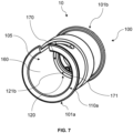
Figure 7 shows another axonometric view of the bushing connection device according toFigure 6 ; -
Figure 8 shows a detailed view of the personal protection device according toFigures 1 and2 comprising the bushing connection device according toFigure 6 ; -
Figure 9 shows a cross-sectional view along the line V-V of the protection device according toFigure 8 . - With reference to the attached figures, some embodiments of a bushing connection device for connecting a
gas generator 15 to aninflatable element 12 are indicated - overall - by thereference number 10. As indicated below, thebushing connection device 10 forms part of an inflation device which, in turn, forms part of apersonal protection device 200, preferably of the wearable type or in the form of a protective garment. In other words, thepersonal protection device 200 comprises thebushing connection device 10 according to one of the embodiments described above. - In particular, the
bushing connection device 10 comprises atubular body 100, namely a sleeve-shaped body or more generally a hollow cylindrical body, which extends between afirst mouth 110a and asecond mouth 110b and defines aninternal cavity 105 able to house aportion 15a of thegas generator 15, intended to allow the outflow of gas. - The tubular body has a
first end region 101a and asecond end region 101b. - The
first end region 101a of thetubular body 100 defines thefirst mouth 110a, namely opens out into thefirst mouth 110a, and thesecond end region 101b of thetubular body 100 defines thesecond mouth 110b, namely opens out into thesecond mouth 110b. In other words, thetubular body 100 is a hollow body, i.e. defining theinternal cavity 105, comprising afirst end portion 101a, which delimits or defines thefirst mouth 110a, and asecond end portion 101b, which delimits or defines thesecond mouth 110b. - Moreover, according to the present invention, the
bushing connection device 10 further comprises avent channel 120 arranged inside thetubular body 100 and extending along at least a portion of thetubular body 100, for venting a fluid of theinflatable element 12. In other words, thevent channel 120 is a venting through-opening arranged at least partially inside thetubular body 100 and is configured to create an independent channel which places the inflatable element and the external environment in fluid communication with each other and does not involve, namely is independent of, theaforementioned portion 15a of thegas generator 15 when the latter is connected to the inflatable element. In particular, thevent channel 120 has a cross-section with a smaller area than thesecond mouth 110b. Namely, the cross-section of thesecond mouth 110b, intended to allow the passage of an inflation fluid towards theinflatable element 12, has a greater area, in fact a much greater area, than the cross-sectional area of thevent channel 120 intended to allow the passage of a fluid exiting theinflatable element 12. - Preferably, the area of the
second mouth 110b in relation to the cross-sectional area of thevent channel 120 is in a ratio of between 1000:1 and 2000:1, preferably between 1400:1 and 1800:1, and even more preferably the ratio is about 1600:1. - In this way, owing to the fact that the through-flow cross-sections are very different and owing to the principles of fluid dynamics and mass conservation, at the time of inflation, since the initial pressure of the air is identical inside the inflatable element and outside, the pressurised inflation fluid passes through the larger cross-section and fills mainly the inflatable element until the pressure inside the inflatable element is at a maximum; once this condition is reached, the fluid rapidly exits the vent channel, because of the difference in pressure between the inside and outside.
- This process is compatible with the need to keep the inflatable element sufficiently inflated for a predetermined period of time, so as to ensure protection for a user at the moment of the impact or blow and then allow venting and deflation of the inflatable element after the impact or blow.
- Preferably, the
vent channel 120 has a cross-sectional area smaller than that of both thesecond mouth 110b and thefirst mouth 110a. - Preferably, in general, the
vent channel 120 is configured to define a through-opening extending between thefirst end region 101a and thesecond end region 101b. In other words, thevent channel 120 is preferably a through-opening at least partially inside thetubular body 100 and extending substantially between thefirst mouth 110a and thesecond mouth 110b. - In particular, preferably the
first end region 101a and thesecond end region 101b are free end regions of thetubular body 100 and the through-opening defined by thevent channel 120 may place in fluid communication with each other an outer zone on the side of the first free end and an outer zone on the side of the second free end. - Preferably, the
vent channel 120 opens out in thefirst end region 101a alongside thefirst mouth 110a and opens out in thesecond end region 101b alongside thesecond mouth 110b, or in thesecond mouth 110b. Namely, thevent channel 120 may open out in thefirst end region 101a and in thesecond end region 101b, respectively, by means of an opening or aperture adjacent or close to thefirst mouth 101a and thesecond mouth 101b, respectively. - Preferably, the
tubular body 100 comprises aside wall 160 or covering portion having a first thickness and incorporating at least partially thefirst end region 101a. Furthermore, thetubular body 100 comprises preferably aninterface rim 170 having a second thickness and incorporating at least partially thesecond end region 101b of thetubular body 100. Namely, theinterface rim 170 forms preferably an interface between the two opposite portions of thetubular body 100 which are configured to be associated respectively with theportion 15a of thegas generator 15 and theinflatable element 12. - In particular, preferably the second thickness of the
interface rim 170 is greater than the first thickness of theside wall 160 so as to define aninternal step 171 of the tubular body, namely a step directed towards theinternal cavity 105 of thetubular body 100. Even more particularly, preferably thevent channel 120 extends continuously in theinterface rim 170 at least between thesecond end region 101b and thestep 171. In other words, theinternal step 171 is defined by the difference in thickness between the second thickness of theinterface rim 170 and the first thickness of theside wall 160 and in particular theinternal step 71 preferably faces the inside of thetubular body 10, namely is located in theinternal cavity 105. - In other words, preferably, the
tubular body 100 of thebushing connection device 10 is divided essentially into at least two portions with a different thickness which interface with each other so as to define theinternal step 171 with a height equal to the difference between the second thickness of theinterface rim 170 and the first thickness of theside wall 160. Thevent channel 120 is confined preferably within theinterface rim 170. This embodiment has the advantage of a smaller extension of the vent channel, thus facilitating the production steps for formation of the vent channel. - In the embodiment shown in
Figures 7 ,8 and9 , thevent channel 120 includes a through-hole 121 arranged in theinterference rim 170 and open between afirst opening 121a positioned in thesecond end region 101b, alongside thesecond mouth 110b, and asecond opening 121b positioned in theinternal step 171. Namely the first opening and the second opening emerge or open out in theend region 101b and in theinternal step 171. The device is configured to allow venting of the inflation fluid by means of a passage across the through-hole and from the through-hole 121 towards thefirst mouth 110a, passing preferably across theinternal cavity 105, for example along an interstice or clearance formed between a wall of theportion 15a of the gas generator and theside wall 160 of thetubular body 100. - In accordance with an alternative embodiment of the device shown for example in
Figure 4 , thevent channel 120 includes, in addition to the through-hole 121, agroove 122 in the side wall facing theinternal cavity 105 of thetubular body 100 and configured to be in fluid communication with the through-hole 121 of thevent channel 120 arranged in theinterface rim 170. Furthermore, preferably thegroove 122 is formed along the inner surface of theside wall 160, namely a surface of the side wall facing theinternal cavity 105, and furthermore thegroove 122 extends preferably between thesecond opening 121b of the through-hole 121 and thefirst mouth 110a of thetubular body 100. - In other words, the
vent channel 120 may be formed by the through-hole 121, arranged inside theinterface rim 170 between thefirst opening 121a and thesecond opening 121b, and by the interspace formed between theside wall 160, as shown in the embodiment ofFigure 7 , or by the through-hole 121, arranged inside the interface rim between thefirst opening 121a and thesecond opening 121b, and by thegroove 122, arranged along the side wall 169 and extending preferably between thesecond opening 121b of the through-hole 121 and thefirst mouth 110a of thetubular body 100, as in the embodiment ofFigure 4 . - Consequently, in the embodiment shown in
Figures 7 ,8 and9 , thevent channel 120 is formed by the through-hole 121 and by the clearance formed between theside wall 160 and thegas generator 15, and theside wall 160 does not have thegroove 122. - Preferably, the
side wall 160 of thetubular body 100 comprises an L-shapedinsertion seat 161 which extends from the first mouth 11a along thefirst end region 101a, namely along theside wall 160. Preferably, moreover, theside wall 160 is shaped so as to allow a stable connection with thegas generator 15, in particular with theportion 15a of thegas generator 15 configured to be removably associated with thebushing connection body 10. For example, theside wall 160 has, at least along the surface facing the internal cavity, a form which mirrors that of the gas generator in such a way as to allow at least partial insertion of thegas generator 15 inside theinternal cavity 105 in a stable manner. The connection between thegas generator 15 and thetubular body 100 does not obstruct thevent channel 120. - Consequently, the
bushing connection device 10 as described here in its embodiments, is also a venting device, namely a device which allows venting of the inflatable element so as to empty it at least partially of the inflation fluid. - As mentioned above, the
bushing connection device 10 according to one of the embodiments described forms part of an inflation device comprising also thegas generator 15 configured to allow inflation of theinflatable element 12. In particular, theportion 15a of thegas generator 15 is inserted in theinternal cavity 105 from the side of thefirst mouth 110a and theportion 15a of thegas generator 15 leaves thevent channel 120 free for venting of the inflation fluid. - Preferably, in the embodiment shown in
Figure 4 , as mentioned above, theportion 15a of thegas generator 15 is inserted in theinternal cavity 105 so as to adhere to a portion of thetubular body 100, and thegroove 122 forms a venting passage with a wall of theportion 15a of thegas generator 15. Furthermore, the venting passage is preferably open towards thefirst mouth 110a. - Alternatively, and again preferably, as mentioned above, in the embodiment shown in
Figures 7 ,8 and9 , theportion 15a of thegas generator 15 is inserted in theinternal cavity 105 with play so as allow venting from theinterface rim 170 towards thefirst mouth 110a. Namely, a wall of theportion 15a of thegas generator 15 forms a clearance thickness, i.e. allowing the passage of a fluid, with an inner surface of the inner wall 106 of thetubular body 100, i.e. a surface facing the internal cavity. - In other words, the
portion 15a of thegas generator 15 is configured in general to allow the passage of the venting fluid. For example, according to a first embodiment of thebushing connection device 10, theportion 15a of the gas generator is inserted in theinternal cavity 105 in an adhering manner and the inflation fluid may cross thegroove 122 of theside wall 160 of thetubular body 100. Alternatively, according to another embodiment of thebushing connection device 10, the inflation fluid may move along an interspace or clearance thickness present between theportion 15a of thegas generator 15 and theside wall 160. - In all the embodiments, as shown by way of example in
Figure 9 , the inflation device is completed byseals first seal 150, of the O-ring type or with a similar ring-like form, is arranged between theportion 15a of thegas generator 15 and thetubular body 100, and asecond seal 152, also with a ring-like form, is arranged between the outer surface of thetubular body 100 and theinflatable element 12. - With regard to the components of the
personal protection device 200, it is pointed out that thepersonal protection device 200 also comprises, in addition to thebushing connection device 10 according to one of the embodiments described above, theinflatable element 12 configured so as to be able to assume a deflated or rest configuration and an inflated or active configuration, namely a configuration in which it is able to protect at least partially a user of the device from blows or impacts. Thepersonal protection device 200 also comprises agas generator 15 configured to allow inflation of the inflatable element from the deflated configuration into the inflated configuration, for example by means of an outflow of pressurised gas from thegas generator 15 towards an inner chamber of theinflatable element 12 following a blow or impact. In particular, in addition thesecond mouth 110b of thebushing connection device 10 opens into the inner chamber of the inflatable element. In other words, when theinflatable element 12 is associated with thebushing connection device 10 thesecond mouth 110b leads into the inner chamber of theinflatable element 12, so as to allow a fluid to pass from theinternal cavity 105 of thetubular body 100 towards the inner chamber of theinflatable element 12. Furthermore, theportion 15a of thegas generator 15 is inserted inside the internal cavity from the side of thefirst mouth 110a. Namely, thepersonal protection device 200 is structured in such a way that theportion 15a of thegas generator 15, which is preferably configured for the outflow of gas, is removably associated with thefirst mouth 110a of thetubular body 100 and in such a way that the inflatable element is removably associated with thebushing connection device 10 at thesecond mouth 110b of thetubular body 100, so as to allow fluid communication between theinternal cavity 105 of the tubular body and the inner chamber of theinflatable element 12. - According to one embodiment, such as that shown in
Figure 4 , theportion 15a of thegas generator 15 is inserted in theinternal cavity 105 so as to adhere to at least a portion of thetubular body 100, and thegroove 122 forms a venting passage with a wall of theportion 15a of thegas generator 15. Furthermore, the venting passage is preferably open towards thefirst mouth 110a. - In other words, the
portion 15a of thegas generator 15, which is preferably configured for the outflow of gas, adheres to at least a portion of thetubular body 100 and thegroove 122 forms a venting passage - namely passage configured to allow the through-flow of a fluid - with a wall of theportion 15a of thegas generator 15. In particular, the venting passage formed by thegroove 122 preferably opens out towards thefirst mouth 110a. In other words, preferably theportion 15a of thegas generator 15 is inserted so as to mate at least partially with the inner surface of thetubular body 100, in particular with the inner surface of thefirst end region 101a. In this way the outer wall of theportion 15a of thegas generator 15 adheres to or is adjacent to at least a portion of the inner surface of thetubular body 100 and defines together with the groove 122 a venting passage configured to allow fluid to pass through between the through-hole 121 arranged in theinterface rim 170 and thefirst mouth 110a. Namely, preferably, when thegas generator 15 is removably associated with thebushing connection device 10, a fluid is allowed to pass along a venting passage situated between thegroove 122 and the outer wall of theportion 15a of thegas generator 15. - According to an alternative embodiment, shown in
Figures 7 ,8 and9 , the wall of theportion 15a of thegas generator 15 forms a venting thickness with thetubular body 100 inside theinternal cavity 105, so as to form a venting passage together with the through-hole 121. Furthermore, the venting passage preferably open out towards thefirst mouth 110a. Namely the venting passage extends along the though-hole 121 formed in theinterface rim 170 and along the interspace formed by the wall of theportion 15a of thegas generator 15 with thetubular body 100. - Preferably, the
inflatable element 12 comprises a connectingportion 12a which envelops or surrounds thetubular body 100 at least partially on one side. Namely, preferably theinflatable element 12 is removably associated with thetubular body 100 by means of the connectingportion 12a which is positioned so as to envelop and/or surround at least partially thetubular body 100 in thesecond end region 101b. Moreover, preferably, as shown by way of example inFigure 9 , thepersonal protection device 200 comprises asleeve 130 or a band-like element configured to be wrapped around the connectingportion 12a of theinflatable element 12 so as to keep said portion associated with thetubular body 100, and for example consists of an elastic sleeve. - Preferably, the
gas generator 15 comprises a pin-like component 71, for example positioned along an outer wall of the generator. - In particular, the L-shaped
insertion seat 161 of theside wall 160 of thetubular body 100, described above, is configured to allow the insertion or passing movement of the pin-like component 71 inside it so as to removably associate thegas generator 15 together with thebushing connection device 10. For example, the pin-like component 71 may be inserted along a first portion of the L-shapedinsertion seat 161 by means of displacement of thegas generator 15 during insertion inside theinternal cavity 105 of thetubular body 100, and the pin-like component 71 may be inserted along a second portion of the L-shapedinsertion seat 161 by means of rotation of the gas generator once inserted inside theinternal cavity 105 of thetubular body 100. - It is clear, therefore, that a fluid, for example an inflation gas, output from the
portion 15a of thegas generator 15 may move along theinternal cavity 105 of thetubular body 100 and enter into the inner chamber of theinflatable element 12 via thesecond mouth 110b, in such a way as to inflate the inflatable element into the inflated configuration. Subsequently, the inflation fluid may flow out of the inner chamber of the inflatable element via thevent channel 120, exiting from thefirst mouth 110a. - In particular, the fluid may enter from the inner chamber of the
inflatable element 12 into the through-hole 121. Depending on the embodiment of the present invention, the fluid may cross the venting passage formed by thegroove 122 and the outer wall of theportion 15a of thegas generator 15, or the venting passage formed by the clearance present between the outer wall of theportion 15a of thegas generator 15 and the tubular body, and then exit from theinternal cavity 105 of thetubular body 100 via thefirst mouth 110a, allowing therefore deflation of the inflatable element. - The present invention also relates to a connection method for connecting a
gas generator 15 to aninflatable element 12. Theinflatable element 12 may form part of apersonal protection device 200 such as that described above, preferably of the wearable type, according to any embodiment. In particular, the connection is such as to ensure fluid communication between thegas generator 15 and theinflatable element 12. The method involves providing abushing connection device 10 comprising atubular body 100 extending between afirst mouth 110a and asecond mouth 110b and defining aninternal cavity 105. The method furthermore involves: - inserting a portion of the
gas generator 15, intended for the outflow of the gas, into theinternal cavity 105 from the side of afirst end region 101a of thetubular body 100 defining thefirst mouth 110a; - placing in fluid communication an inner chamber of the
inflatable element 12 by means of asecond end region 101b of thetubular body 100 defining thesecond mouth 110b. - In particular, in order to inflate the
inflatable element 12, thegas generator 15 emits a gas which passes from thesecond mouth 110b towards the inner chamber of theinflatable element 12. Furthermore, in order to deflate theinflatable element 12, the gas flows out via a vent channel extending between thefirst end region 101a and thesecond end region 101b. In particular, thevent channel 120 has a cross-section with a smaller area than thesecond mouth 110b, and preferably also than thefirst mouth 110a. - Preferably, according to the method, the gas may flow out of the inner chamber of the
inflatable element 12 by means of thevent channel 120, passing from afirst opening 121a, positioned in the second end region 101 alongside the second mouth 110n, towards a zone alongside thefirst mouth 110a. For example, the zone alongside thefirst mouth 110a may be a tangential zone of thefirst mouth 110a, i.e. therefore located on an outer edge of thefirst mouth 110a. - The subject-matter of the present disclosure has been described hitherto with reference to its embodiments. It is to be understood that other embodiments relating to the same inventive idea may exist, all of these falling within the scope of protection of the claims which are attached below.
Claims (18)
- Personal protection device (200) comprising an inflatable element (12) and an inflation device, wherein the inflation device comprises a gas generator (15) and a bushing connection device (10) configured to connect said gas generator (15) with said inflatable element (12), wherein said bushing connection device (10) comprises a tubular body (100) extending between a first mouth (110a) and a second mouth (110b) and defining an internal cavity (105) able to house a portion (15a) of the gas generator (15) intended for the gas outflow,wherein a first end region (101a) of the tubular body defines said first mouth (110a) and a second end region (101b) of the tubular body (100) defines said second mouth (110b), and whereinsaid portion (15a) of the gas generator (15) is inserted into said internal cavity (105) from the side of said first mouth (10a) of the tubular body,said inflatable member (12) is configured to be able to assume a deflated or rest configuration and an inflated or active configuration, wherein the gas generator (15) is configured to allow inflation of said inflatable element (12) from said deflated configuration into said inflated configuration, wherein said second mouth (110b) of the tubular body opens into the inner chamber of said inflatable element (12)and wherein said bushing connection device (10) further comprises a vent channel (120) extending along at least a portion of said tubular body (100) for venting an inflation fluid of said inflatable element (12), wherein said vent channel (120) has a cross-section with a smaller area than at least said second mouth (110b), and said portion (15a) of the gas generator (15) is configured to leave said vent channel (120) free to vent the inflation fluid.
- Personal protection device (200) according to the preceding claim, wherein the vent channel (120) is arranged at least partially inside said tubular body (100).
- Personal protection device (200) according to claim 1 or 2, wherein the tubular body (100) comprises a side wall (160), or covering portion, having a first thickness and at least partially incorporating said first end region (101a) and the tubular body (100) comprises an interface rim (170) having a second thickness and at least partially incorporating said second end region (101b) of the tubular body (100), wherein the second thickness of the interface rim (170) is greater than the first thickness of said side wall (160), so as to define an internal step (171), and wherein said vent channel (120) extends at least into said interface rim (170).
- Personal protection device (200) according to the preceding claim, wherein said vent channel (120) includes a through-hole (121) arranged in the interface rim (170) and open between a first opening (121a) positioned in said second end region (101b) alongside said second mouth (110b) and a second opening (121b) positioned in said internal step (170).
- Personal protection device (200) according to any one of the preceding claims, wherein said vent channel (120) is configured to define a through-gap extending between the first end region (101a) and the second end region (101b).
- Personal protection device (200) according to any one of the preceding claims, wherein said vent channel (120) opens out in the first end region (101a) alongside the first mouth (110a) and in the second end region (101b) alongside the second mouth (110b).
- Personal protection device (200) according to any one of the preceding claims in combination with claim 4, wherein said vent channel (120) further includes a groove (122) in said side wall (160), said groove (122) facing said internal cavity (105) and being in fluid communication with said through-hole (121), and wherein the groove (122) is formed along the internal surface of said side wall (160), wherein said groove (122) extends between said second opening (121b) of said through-hole (121) and said first mouth (110a).
- Personal protection device (200) according to one of the preceding claims in combination with claim 3, wherein said side wall (160) of the tubular body (100) comprises an L-shaped insertion seat (161) which extends from said first mouth (110a) along said first end region (101a), and wherein said vent channel (120) is independent of said insertion seat (161).
- Personal protection device (200) according to one of the preceding claims, wherein said bushing connection device (10) is also a venting device.
- Personal protection device (200) according to one of the preceding claims in combination with claim 7, wherein said portion (15a) of the gas generator (15) is inserted inside said internal cavity (105) so as to adhere with at least a portion of said tubular body (100), and said groove (122) forms a vent passage with a wall of said portion (15) of the gas generator (15a), said vent passage being open towards said first mouth (110a).
- Personal protection device (200) according to one of the preceding claims in combination with claim 3, wherein said portion (15a) of the gas generator (15) is inserted into said internal cavity (105) with clearance so as to allow venting from said interface rim (170) towards said first mouth (110a).
- Personal protection device (200) according to one of the preceding claims, wherein said inflatable element (12) comprises a connecting portion (12a) which envelops and surrounds said tubular body (100) on an outer side.
- Personal protection device (200) according to the preceding claim in combination with claim 8, wherein said gas generator (15) comprises a pin-like component (71), and wherein said L-shaped insertion seat (161) is configured to allow passage of said pin-like component (71) inside it so as to removably associate said gas generator (15) with said bushing connection device (10).
- Personal protection device (200) according to one of the preceding claims, wherein said protection device is a wearable device or is in the form of a protective garment.
- Connection method for connecting a gas generator (15) with an inflatable element (12), wherein a bushing connection device (10) is provided, said device comprising a tubular body (100) extending between a first mouth (110a) and a second mouth (110b) and defining an internal cavity (105), wherein said method involves:- inserting a portion (15a) of the gas generator (15) intended for the outflow of the gas into said internal cavity (105) from the side of a first end region (101a) of the tubular body (100) defining said first mouth (110a),- placing an inner chamber of the inflatable element (12) in fluid communication by means of a second end region (101b) of the tubular body (100) defining said second mouth (110b),wherein, in order to inflate said inflatable element (12), the gas generator (15) emits gas passing from the second mouth (110b) towards the inner chamber of the inflatable element (12),and wherein, in order to deflate said inflatable element (12), said gas flows out through a vent channel (120) extending at least partially along said tubular body (100), wherein the vent channel (120) has a cross-section with a smaller area than at least said second mouth (110b).
- Method according to the preceding claim, wherein said gas flows out from the inner chamber of the inflatable element (12) through said vent channel (120) passing through an opening (121a), positioned in said second end region (101b) next to said second mouth (110b).
- Method according to the preceding claim, wherein the vent channel (120) extends from the opening (121a) into a through-hole (121) and as far as an interspace between the tubular body (100) and the gas generator (15), or wherein the vent channel (120) extends from the opening (121a) into a through-hole (121) and as far as a groove (122) formed on an inner side of the tubular body (100).
- Method according to any one of claims 15 to 17, wherein the inflatable element (12) is the inflatable element of a wearable personal protection device.
Applications Claiming Priority (1)
| Application Number | Priority Date | Filing Date | Title |
|---|---|---|---|
| IT102022000021045A IT202200021045A1 (en) | 2022-10-12 | 2022-10-12 | SOCKET CONNECTION DEVICE AND PERSONAL PROTECTION DEVICE INCLUDING SAID SOCKET CONNECTION DEVICE |
Publications (2)
| Publication Number | Publication Date |
|---|---|
| EP4353110A1 true EP4353110A1 (en) | 2024-04-17 |
| EP4353110B1 EP4353110B1 (en) | 2025-06-11 |
Family
ID=84942973
Family Applications (1)
| Application Number | Title | Priority Date | Filing Date |
|---|---|---|---|
| EP23202810.0A Active EP4353110B1 (en) | 2022-10-12 | 2023-10-10 | Personal protection device including a bushing connection device |
Country Status (2)
| Country | Link |
|---|---|
| EP (1) | EP4353110B1 (en) |
| IT (1) | IT202200021045A1 (en) |
Citations (3)
| Publication number | Priority date | Publication date | Assignee | Title |
|---|---|---|---|---|
| EP1845298B1 (en) * | 2006-04-03 | 2012-01-11 | NovaLung GmbH | Coupling for tubular elements |
| EP2373189B2 (en) * | 2008-12-09 | 2021-01-06 | DAINESE S.p.A. | Personal protection device and garment including such a device |
| EP4046514A1 (en) * | 2021-02-18 | 2022-08-24 | Dainese S.p.A. | Inflation device and personal protection device including said inflation device |
-
2022
- 2022-10-12 IT IT102022000021045A patent/IT202200021045A1/en unknown
-
2023
- 2023-10-10 EP EP23202810.0A patent/EP4353110B1/en active Active
Patent Citations (3)
| Publication number | Priority date | Publication date | Assignee | Title |
|---|---|---|---|---|
| EP1845298B1 (en) * | 2006-04-03 | 2012-01-11 | NovaLung GmbH | Coupling for tubular elements |
| EP2373189B2 (en) * | 2008-12-09 | 2021-01-06 | DAINESE S.p.A. | Personal protection device and garment including such a device |
| EP4046514A1 (en) * | 2021-02-18 | 2022-08-24 | Dainese S.p.A. | Inflation device and personal protection device including said inflation device |
Also Published As
| Publication number | Publication date |
|---|---|
| EP4353110B1 (en) | 2025-06-11 |
| IT202200021045A1 (en) | 2024-04-12 |
Similar Documents
| Publication | Publication Date | Title |
|---|---|---|
| US4693696A (en) | Inflated balloon tire for toy vehicles | |
| CN102026851B (en) | Airbag inflator with adaptive valve | |
| US3887213A (en) | Inflatable vehicle occupant restraint and system therefor | |
| US4014048A (en) | Inflation device | |
| KR20040040365A (en) | Improvements in or relating to an air-bag arrangement | |
| US20110012328A1 (en) | Side curtain airbag with pressure control device | |
| EP0949123A1 (en) | Airbag for front passenger and folding method thereof | |
| CA2248700A1 (en) | Catheter with autoinflating, autoregulating balloon | |
| EP1112902A3 (en) | Adaptive inflation mechanism | |
| DE69506202D1 (en) | Airbag flow regulating valve | |
| DE19812221A1 (en) | Airbag inflating system for vehicle occupant safety protection system | |
| US7828325B2 (en) | Air-bag and a method of controlling pressure within an air-bag | |
| CN101687487A (en) | Venting device for an airbag inflator | |
| US6357502B1 (en) | Tire wheel and its components | |
| WO1996034781A1 (en) | Process for folding an airbag for a passenger restraint system | |
| EP1531070A3 (en) | Vehicle pressure relief valve having centrally secured flaps and method of manufacturing the same | |
| EP4353110A1 (en) | Personal protection device including a bushing connection device | |
| KR102683792B1 (en) | Airbag for vehicle | |
| US20020124925A1 (en) | Inner tube and wheel formed by a tyre, a rim, and the inner tube | |
| US6357468B1 (en) | Universal valve | |
| US5280952A (en) | Airbag arrangement for an automotive vehicle | |
| US5180455A (en) | Pneumatic tire and improved inflation and deflation valve device | |
| EP3157766B1 (en) | A filling device for an inflatable unit | |
| ES2283639T3 (en) | AIRBAG WITH A VARIABLE SURFACE VENTILATION AREA. | |
| EP0922592A1 (en) | Tyre wheel and its components |
Legal Events
| Date | Code | Title | Description |
|---|---|---|---|
| PUAI | Public reference made under article 153(3) epc to a published international application that has entered the european phase |
Free format text: ORIGINAL CODE: 0009012 |
|
| STAA | Information on the status of an ep patent application or granted ep patent |
Free format text: STATUS: THE APPLICATION HAS BEEN PUBLISHED |
|
| AK | Designated contracting states |
Kind code of ref document: A1 Designated state(s): AL AT BE BG CH CY CZ DE DK EE ES FI FR GB GR HR HU IE IS IT LI LT LU LV MC ME MK MT NL NO PL PT RO RS SE SI SK SM TR |
|
| STAA | Information on the status of an ep patent application or granted ep patent |
Free format text: STATUS: REQUEST FOR EXAMINATION WAS MADE |
|
| 17P | Request for examination filed |
Effective date: 20240822 |
|
| RBV | Designated contracting states (corrected) |
Designated state(s): AL AT BE BG CH CY CZ DE DK EE ES FI FR GB GR HR HU IE IS IT LI LT LU LV MC ME MK MT NL NO PL PT RO RS SE SI SK SM TR |
|
| GRAP | Despatch of communication of intention to grant a patent |
Free format text: ORIGINAL CODE: EPIDOSNIGR1 |
|
| STAA | Information on the status of an ep patent application or granted ep patent |
Free format text: STATUS: GRANT OF PATENT IS INTENDED |
|
| INTG | Intention to grant announced |
Effective date: 20250109 |
|
| GRAS | Grant fee paid |
Free format text: ORIGINAL CODE: EPIDOSNIGR3 |
|
| GRAA | (expected) grant |
Free format text: ORIGINAL CODE: 0009210 |
|
| STAA | Information on the status of an ep patent application or granted ep patent |
Free format text: STATUS: THE PATENT HAS BEEN GRANTED |
|
| AK | Designated contracting states |
Kind code of ref document: B1 Designated state(s): AL AT BE BG CH CY CZ DE DK EE ES FI FR GB GR HR HU IE IS IT LI LT LU LV MC ME MK MT NL NO PL PT RO RS SE SI SK SM TR |
|
| REG | Reference to a national code |
Ref country code: GB Ref legal event code: FG4D |
|
| REG | Reference to a national code |
Ref country code: CH Ref legal event code: EP |
|
| REG | Reference to a national code |
Ref country code: DE Ref legal event code: R096 Ref document number: 602023003944 Country of ref document: DE |
|
| REG | Reference to a national code |
Ref country code: IE Ref legal event code: FG4D |
|
| PG25 | Lapsed in a contracting state [announced via postgrant information from national office to epo] |
Ref country code: ES Free format text: LAPSE BECAUSE OF FAILURE TO SUBMIT A TRANSLATION OF THE DESCRIPTION OR TO PAY THE FEE WITHIN THE PRESCRIBED TIME-LIMIT Effective date: 20250611 Ref country code: FI Free format text: LAPSE BECAUSE OF FAILURE TO SUBMIT A TRANSLATION OF THE DESCRIPTION OR TO PAY THE FEE WITHIN THE PRESCRIBED TIME-LIMIT Effective date: 20250611 |
|
| REG | Reference to a national code |
Ref country code: LT Ref legal event code: MG9D |
|
| PG25 | Lapsed in a contracting state [announced via postgrant information from national office to epo] |
Ref country code: GR Free format text: LAPSE BECAUSE OF FAILURE TO SUBMIT A TRANSLATION OF THE DESCRIPTION OR TO PAY THE FEE WITHIN THE PRESCRIBED TIME-LIMIT Effective date: 20250912 Ref country code: NO Free format text: LAPSE BECAUSE OF FAILURE TO SUBMIT A TRANSLATION OF THE DESCRIPTION OR TO PAY THE FEE WITHIN THE PRESCRIBED TIME-LIMIT Effective date: 20250911 |
|
| REG | Reference to a national code |
Ref country code: NL Ref legal event code: MP Effective date: 20250611 |
|
| PG25 | Lapsed in a contracting state [announced via postgrant information from national office to epo] |
Ref country code: BG Free format text: LAPSE BECAUSE OF FAILURE TO SUBMIT A TRANSLATION OF THE DESCRIPTION OR TO PAY THE FEE WITHIN THE PRESCRIBED TIME-LIMIT Effective date: 20250611 |
|
| PG25 | Lapsed in a contracting state [announced via postgrant information from national office to epo] |
Ref country code: HR Free format text: LAPSE BECAUSE OF FAILURE TO SUBMIT A TRANSLATION OF THE DESCRIPTION OR TO PAY THE FEE WITHIN THE PRESCRIBED TIME-LIMIT Effective date: 20250611 |
|
| PG25 | Lapsed in a contracting state [announced via postgrant information from national office to epo] |
Ref country code: RS Free format text: LAPSE BECAUSE OF FAILURE TO SUBMIT A TRANSLATION OF THE DESCRIPTION OR TO PAY THE FEE WITHIN THE PRESCRIBED TIME-LIMIT Effective date: 20250911 |
|
| PG25 | Lapsed in a contracting state [announced via postgrant information from national office to epo] |
Ref country code: LV Free format text: LAPSE BECAUSE OF FAILURE TO SUBMIT A TRANSLATION OF THE DESCRIPTION OR TO PAY THE FEE WITHIN THE PRESCRIBED TIME-LIMIT Effective date: 20250611 |
|
| PG25 | Lapsed in a contracting state [announced via postgrant information from national office to epo] |
Ref country code: NL Free format text: LAPSE BECAUSE OF FAILURE TO SUBMIT A TRANSLATION OF THE DESCRIPTION OR TO PAY THE FEE WITHIN THE PRESCRIBED TIME-LIMIT Effective date: 20250611 |
|
| PG25 | Lapsed in a contracting state [announced via postgrant information from national office to epo] |
Ref country code: PT Free format text: LAPSE BECAUSE OF FAILURE TO SUBMIT A TRANSLATION OF THE DESCRIPTION OR TO PAY THE FEE WITHIN THE PRESCRIBED TIME-LIMIT Effective date: 20251013 |
|
| REG | Reference to a national code |
Ref country code: AT Ref legal event code: MK05 Ref document number: 1801683 Country of ref document: AT Kind code of ref document: T Effective date: 20250611 |
|
| PG25 | Lapsed in a contracting state [announced via postgrant information from national office to epo] |
Ref country code: IS Free format text: LAPSE BECAUSE OF FAILURE TO SUBMIT A TRANSLATION OF THE DESCRIPTION OR TO PAY THE FEE WITHIN THE PRESCRIBED TIME-LIMIT Effective date: 20251011 |
|
| PG25 | Lapsed in a contracting state [announced via postgrant information from national office to epo] |
Ref country code: SM Free format text: LAPSE BECAUSE OF FAILURE TO SUBMIT A TRANSLATION OF THE DESCRIPTION OR TO PAY THE FEE WITHIN THE PRESCRIBED TIME-LIMIT Effective date: 20250611 Ref country code: AT Free format text: LAPSE BECAUSE OF FAILURE TO SUBMIT A TRANSLATION OF THE DESCRIPTION OR TO PAY THE FEE WITHIN THE PRESCRIBED TIME-LIMIT Effective date: 20250611 |
|
| PG25 | Lapsed in a contracting state [announced via postgrant information from national office to epo] |
Ref country code: CZ Free format text: LAPSE BECAUSE OF FAILURE TO SUBMIT A TRANSLATION OF THE DESCRIPTION OR TO PAY THE FEE WITHIN THE PRESCRIBED TIME-LIMIT Effective date: 20250611 |
|
| PG25 | Lapsed in a contracting state [announced via postgrant information from national office to epo] |
Ref country code: PL Free format text: LAPSE BECAUSE OF FAILURE TO SUBMIT A TRANSLATION OF THE DESCRIPTION OR TO PAY THE FEE WITHIN THE PRESCRIBED TIME-LIMIT Effective date: 20250611 |
|
| PG25 | Lapsed in a contracting state [announced via postgrant information from national office to epo] |
Ref country code: EE Free format text: LAPSE BECAUSE OF FAILURE TO SUBMIT A TRANSLATION OF THE DESCRIPTION OR TO PAY THE FEE WITHIN THE PRESCRIBED TIME-LIMIT Effective date: 20250611 |
|
| PG25 | Lapsed in a contracting state [announced via postgrant information from national office to epo] |
Ref country code: SK Free format text: LAPSE BECAUSE OF FAILURE TO SUBMIT A TRANSLATION OF THE DESCRIPTION OR TO PAY THE FEE WITHIN THE PRESCRIBED TIME-LIMIT Effective date: 20250611 |
|
| PG25 | Lapsed in a contracting state [announced via postgrant information from national office to epo] |
Ref country code: RO Free format text: LAPSE BECAUSE OF FAILURE TO SUBMIT A TRANSLATION OF THE DESCRIPTION OR TO PAY THE FEE WITHIN THE PRESCRIBED TIME-LIMIT Effective date: 20250611 |
|
| REG | Reference to a national code |
Ref country code: DE Ref legal event code: R097 Ref document number: 602023003944 Country of ref document: DE |
|
| PG25 | Lapsed in a contracting state [announced via postgrant information from national office to epo] |
Ref country code: DK Free format text: LAPSE BECAUSE OF FAILURE TO SUBMIT A TRANSLATION OF THE DESCRIPTION OR TO PAY THE FEE WITHIN THE PRESCRIBED TIME-LIMIT Effective date: 20250611 |
|
| PG25 | Lapsed in a contracting state [announced via postgrant information from national office to epo] |
Ref country code: IT Free format text: LAPSE BECAUSE OF FAILURE TO SUBMIT A TRANSLATION OF THE DESCRIPTION OR TO PAY THE FEE WITHIN THE PRESCRIBED TIME-LIMIT Effective date: 20250611 |
|
| PLBE | No opposition filed within time limit |
Free format text: ORIGINAL CODE: 0009261 |
|
| STAA | Information on the status of an ep patent application or granted ep patent |
Free format text: STATUS: NO OPPOSITION FILED WITHIN TIME LIMIT |
|
| REG | Reference to a national code |
Ref country code: CH Ref legal event code: L10 Free format text: ST27 STATUS EVENT CODE: U-0-0-L10-L00 (AS PROVIDED BY THE NATIONAL OFFICE) Effective date: 20260423 |