EP4353104A1 - Atomizer and aerosol generating device - Google Patents
Atomizer and aerosol generating device Download PDFInfo
- Publication number
- EP4353104A1 EP4353104A1 EP22804011.9A EP22804011A EP4353104A1 EP 4353104 A1 EP4353104 A1 EP 4353104A1 EP 22804011 A EP22804011 A EP 22804011A EP 4353104 A1 EP4353104 A1 EP 4353104A1
- Authority
- EP
- European Patent Office
- Prior art keywords
- airflow channel
- air inlet
- vaporization
- housing
- base
- Prior art date
- Legal status (The legal status is an assumption and is not a legal conclusion. Google has not performed a legal analysis and makes no representation as to the accuracy of the status listed.)
- Pending
Links
Images




Classifications
-
- A—HUMAN NECESSITIES
- A24—TOBACCO; CIGARS; CIGARETTES; SIMULATED SMOKING DEVICES; SMOKERS' REQUISITES
- A24F—SMOKERS' REQUISITES; MATCH BOXES; SIMULATED SMOKING DEVICES
- A24F40/00—Electrically operated smoking devices; Component parts thereof; Manufacture thereof; Maintenance or testing thereof; Charging means specially adapted therefor
- A24F40/40—Constructional details, e.g. connection of cartridges and battery parts
- A24F40/48—Fluid transfer means, e.g. pumps
- A24F40/485—Valves; Apertures
-
- A—HUMAN NECESSITIES
- A24—TOBACCO; CIGARS; CIGARETTES; SIMULATED SMOKING DEVICES; SMOKERS' REQUISITES
- A24F—SMOKERS' REQUISITES; MATCH BOXES; SIMULATED SMOKING DEVICES
- A24F40/00—Electrically operated smoking devices; Component parts thereof; Manufacture thereof; Maintenance or testing thereof; Charging means specially adapted therefor
- A24F40/40—Constructional details, e.g. connection of cartridges and battery parts
- A24F40/48—Fluid transfer means, e.g. pumps
-
- A—HUMAN NECESSITIES
- A24—TOBACCO; CIGARS; CIGARETTES; SIMULATED SMOKING DEVICES; SMOKERS' REQUISITES
- A24F—SMOKERS' REQUISITES; MATCH BOXES; SIMULATED SMOKING DEVICES
- A24F40/00—Electrically operated smoking devices; Component parts thereof; Manufacture thereof; Maintenance or testing thereof; Charging means specially adapted therefor
- A24F40/10—Devices using liquid inhalable precursors
-
- A—HUMAN NECESSITIES
- A24—TOBACCO; CIGARS; CIGARETTES; SIMULATED SMOKING DEVICES; SMOKERS' REQUISITES
- A24F—SMOKERS' REQUISITES; MATCH BOXES; SIMULATED SMOKING DEVICES
- A24F40/00—Electrically operated smoking devices; Component parts thereof; Manufacture thereof; Maintenance or testing thereof; Charging means specially adapted therefor
- A24F40/40—Constructional details, e.g. connection of cartridges and battery parts
- A24F40/42—Cartridges or containers for inhalable precursors
Definitions
- This application belongs to the field of aerosol generation device technologies and relates to a vaporizer and an aerosol generation device.
- An aerosol generation device includes a vaporizer and a power supply device.
- An air inlet in the vaporizer is generally disposed directly facing a vaporization component.
- an embodiment of this application provides a vaporizer, including a housing provided with an open end, where a liquid storage cavity for storing a liquid substrate and a vaporization component for vaporizing the liquid substrate to form an aerosol are provided in the housing; and a base, connected to the open end of the housing, where at least a part of the base defines an air inlet for entry of external air, the base and the vaporization component jointly define a vaporization cavity, and the vaporization cavity and the air inlet are in fluid communication through an airflow channel, where the airflow channel includes at least one first airflow channel and at least one second airflow channel, the first airflow channel extends in a direction from the air inlet toward the vaporization cavity, and the second airflow channel extends on the base and is roughly perpendicular to the extending direction of the first airflow channel.
- a sealing gasket is provided in the base, the sealing gasket has a vent hole, and the vent hole connects the first airflow channel to the vaporization cavity; and the vaporization component includes a porous body and a heating element, and the vent hole is disposed directly facing the heating element.
- At least a part of the sealing gasket defines at least one buffer region capable of storing a condensate; and at least one diversion portion is provided on the sealing gasket, and the condensate is capable of entering the buffer region along the diversion portion.
- the base is provided with a bottom surface, and the air inlet is defined by a first groove formed by recessing at least a part of the bottom surface.
- an electrode that is connected to the vaporization component and supplies power to the vaporization component is further included, where two electrode mounting holes are provided on the bottom surface, where a hole diameter of an end portion of at least one electrode mounting hole is greater than an outer diameter of the electrode column, to form a third airflow channel between the electrode column and the electrode mounting hole, and the third airflow channel connects the air inlet to the second airflow channel in a short axis direction of the housing.
- the electrode column has a fixing portion mounted on the bottom surface, and at least a part of the fixing end covers an air inlet end of the first airflow channel.
- At least a part of the bottom surface is recessed to form two second grooves, and the fixing portion is capable of being fixedly mounted in the second grooves; and the second grooves are located on two sides of the air inlet.
- At least a part of a surface of the second groove is recessed to form at least one third groove, and the third groove defines the second airflow channel.
- the second airflow channel is on a straight line on which the air inlet extends transversely in a short axis direction of the housing.
- the first airflow channel is located on the base or is jointly defined by the housing and the base.
- This application further provides an aerosol generation device, including the foregoing vaporizer and a power supply device for supplying power to the vaporizer for driving.
- the beneficial effect of this application is that since the air inlet is disposed roughly perpendicular to the first airflow channel and then is in communication with the vaporization cavity, a liquid in the vaporization cavity cannot enter the air inlet, which alleviates the problem that the liquid in the vaporizer leaks from the air inlet.
- This application provides an aerosol generation device, referring to FIG. 1 , including a vaporizer 100 and a power supply device 200.
- the vaporizer 100 stores an aerosol-forming substrate and can vaporize the aerosol-forming substrate to form an aerosol.
- the power supply device 200 supplies power to the vaporizer 100 for driving.
- the vaporizer 100 and the power supply device 200 may be fixedly connected or detachably connected.
- the vaporizer 100 provided in this application is detachably connected to the power supply device 200, such as magnetic connection, snap-fit connection, and the like.
- the specific connection method is not limited.
- the power supply device 200 can be divided into two parts in a longitudinal direction.
- a first part 201 can accommodate at least a part of a surface of the vaporizer 100, and a second part 202 can accommodate other components that constitute the power supply device, such as a battery, a control module, a charging module, and the like.
- the vaporizer 100 includes a housing 10.
- the housing 10 is provided with a proximal end and a distal end that are longitudinally opposite.
- the proximal end is provided with a suction nozzle opening 11, and the aerosol can be output to the outside of the housing 10 through the suction nozzle opening 11.
- the distal end is open to facilitate mounting of other functional components of the vaporizer 100 inside the housing 10.
- a liquid storage cavity 12 of a liquid storage substrate for storing a liquid substrate and a vaporization component 20 for vaporizing the liquid substrate to form an aerosol are provided in the housing 10.
- the vaporization component 20 includes a porous body 21 and a heating element 22 for heating the liquid substrate absorbed by the porous body 21.
- the porous body 21 may be made of a hard capillary structure such as porous ceramic, porous glass ceramic, or porous glass.
- a porous ceramic material is preferred and is generally formed by high-temperature sintering of aggregate, a binder, a pore-forming agent, and other components.
- the material has a large quantity of pore structures inside that are in communication with each other and in communication with a surface of the material.
- the liquid substrate can penetrate into the interior through the surface of the porous body 21 and be vaporized by the heating element 42 to form the aerosol.
- the heating element 22 may be a heating coating, a heating sheet, or a heating mesh.
- the heating coating may include, but is not limited to, an electromagnetic induction heating coating, an infrared induction heating coating, and the like.
- the heating sheet or the heating mesh is embedded and fixed in the surface of the porous body.
- the heating element is formed on the surface of the porous body 21 by mixing conductive raw material powder and printing auxiliaries into paste and sintering after printing, and has effects of high vaporizing efficiency, less heat loss, and preventing or greatly reducing dry burning.
- the heating element 22 may be made of a material such as stainless steel, nickel chromium alloy, iron chromium aluminum alloy, or metal titanium.
- a shape of the porous body 21 is constructed into a roughly block-shaped structure in this embodiment.
- a top surface is roughly H-shaped, a left side surface and a right side surface are roughly U-shaped, a front side surface, a rear side surface, and a bottom surface are square, and a groove 23 is formed in the middle.
- the groove 23 can be used to temporarily store the liquid substrate and increase a diffusion speed of the liquid substrate inside the porous body 21.
- the specific shape of the porous body 21 can be changed according to needs and is not limited to a specific shape.
- a bottom surface of the groove 23 forms a liquid absorbing surface 211.
- the heating element 22 is formed on the bottom surface of the porous body 21, and the bottom surface becomes a vaporization surface 212.
- the housing 10 is further provided with a fixing bracket 30 for fixing the vaporization component 20 inside the housing 10, and a sealing sleeve 40 for sealing the liquid storage cavity 12.
- the fixing bracket 30 is provided with an accommodating portion 31, and the accommodating portion 31 is provided with an accommodating cavity 311. At least a part of the surface of the vaporization component 20 can be fixedly held inside the accommodating cavity 311.
- An end of the fixing bracket 30 that faces the liquid storage cavity 12 is further provided with a diversion portion 32.
- the diversion portion 32 is provided with at least one first liquid guiding hole 321 in fluid communication with the liquid storage cavity 12.
- the sealing sleeve 40 is sleeved on an outer wall of the diversion portion 32.
- the sealing sleeve 40 is also provided with at least one second liquid guiding hole 41 that is in communication with the first liquid guiding hole 321.
- first liquid guiding holes 321 are provided on a left side and a right side of the diversion portion 32, and two second liquid guiding holes 41 are provided on the sealing sleeve 40 at corresponding positions, and the cross-sections of the first liquid guiding holes 321 and the second liquid guiding holes 41 that are perpendicular to the axial direction of the housing 10 have a same size and shape, to improve the transfer efficiency of the liquid substrate.
- a sealing member 50 is further provided between the two contact surfaces.
- the sealing member 50 is made of a flexible silicone material, so that the fixing bracket 30 and the surface of the porous body 21 are tightly fixed.
- the sealing member 50 is provided with a third liquid guiding hole 51 at a position opposite to the first liquid guiding hole 321.
- a quantity of third liquid guiding holes 51 is the same as a quantity of first liquid guiding holes 321 and a quantity of second liquid guiding holes 41. The specific quantity can be adjusted and designed according to transfer rate requirements of the liquid substrate, and is not limited herein.
- the third liquid guiding hole 51 is in longitudinal communication with the groove 23 in the middle of the porous body 21.
- a plurality of convex ribs are provided on an outer surface of the sealing member 50. The convex ribs can strengthen the fixed connection between the sealing member 50 and an inner wall of the fixing bracket 30.
- the housing 10 is further provided with an air outlet pipe 13.
- An air outlet end of the air outlet pipe 13 is in communication with the suction nozzle opening 11.
- the aerosol formed through vaporization performed by the vaporization component 20 can be output to the outside of the housing 10 through the air outlet pipe 13.
- the air outlet pipe 13 is located in the middle of the liquid storage cavity 12 and can be formed by extending at least a part of an inner wall surface of the housing 10 longitudinally.
- An air inlet end of the air outlet pipe 13 longitudinally abuts against the sealing sleeve 40.
- the sealing sleeve 40 is provided with a first air outlet hole 42 at a corresponding position.
- the diversion portion 32 of the fixing bracket is provided with a second air outlet hole 322 at a corresponding position.
- the air outlet pipe is located in the middle of the liquid storage cavity 12
- the first air outlet hole 42 is located between the two second liquid guiding holes 41
- the second air outlet hole 322 is located between the two first liquid guiding holes 321.
- the air outlet pipe 13, the first air outlet hole 42, and the second air outlet hole 322 are in longitudinal communication along the housing 10 to improve the output efficiency of the aerosol.
- the porous body 21 of the vaporization component is fixed in the accommodating portion 31.
- the accommodating cavity 311 of the accommodating portion 31 is defined by a top surface 312, a first side wall 313, and a second side wall 314.
- the first side wall 313 and the second side wall 314 are spaced apart, and a first gap 331 and a second gap 332 are formed in the middle.
- the first gap 331 is disposed opposite to the second gap 332.
- the aerosol formed through vaporization performed by the heating element 22 can enter the second air outlet hole 332 and the first air outlet hole 42 through the first gap 331 and/or the second gap 332, and then enter the air outlet pipe 13.
- an open end 14 of the housing 10 is covered with a base 60.
- the base 60 is provided with a bottom surface 61 covering the open end 12, and a body portion 62.
- At least one first buckle 621 is provided on an outer wall surface of the body portion 62, and at least one first gap 15 is provided on the housing 10.
- the first buckle 621 and the first gap 15 match each other, so that the base 60 and the housing 10 are fixedly connected.
- four first buckles 621 are provided at intervals on the outer wall of the body portion 62, and four first gaps 15 are provided correspondingly at intervals on the housing 10.
- the base 60 is further provided with a first support arm 631 and a second support arm 632.
- the first support arm 631 and the second support arm 632 are disposed opposite to each other and located above the body portion 62.
- the base 60 and the fixing bracket 30 are fixedly connected. Specifically, referring to FIG. 4 to FIG. 6 , parts of outer wall surfaces on two sides of the diversion portion 31 protrude outward to form flanges 323.
- a first accommodating region 341 is formed between the left flange 323 and the first side wall 313.
- a second accommodating region 342 is formed between the right flange and the second side wall 314.
- a part of the first support arm 631 can be accommodated in the first accommodating region 341, and a part of the second support arm 632 can be accommodated in the second accommodating region 342.
- a second buckle 35 is provided on an outer wall surface at a lower end of each of the first side wall 313 and the second side wall 314, and a second gap 64 is provided on each of the first support arm 631 and the second support arm 632.
- the second buckles 35 and the second gaps 64 provided on the left side and the right side are fixedly connected, so that the base 60 and the fixing bracket 30 are tightly connected.
- a plurality of capillary grooves are transversely provided on the first side wall 313 and the second side wall 314 of the fixing bracket, and the outer wall surfaces of the first support arm 631 and the second support arm 632 of the base.
- the capillary grooves form a stacked structure, which can buffer the liquid substrate, and prevent the liquid substrate from further leaking downward, to further improve a leak-proof function of the entire vaporizer 100.
- the vaporization component 20 is accommodated in the accommodating cavity 311 of the fixing bracket.
- the vaporization surface 212 is disposed directly facing the body portion 62 of the base.
- the vaporization surface 212 and the body portion 62 jointly define the vaporization cavity 24.
- the body portion 62 defines a receiving cavity 622.
- At least a part of the base 60 defines an air inlet 80 for entry of external air.
- at least a part of the bottom surface 61 of the base is recessed inward to form a first groove 65, and the first groove 65 defines the air inlet 80.
- the air inlet 80 extends transversely in a short axis direction of the housing 10.
- Two electrode mounting holes 66 are provided on two sides of the air inlet 80, namely, a positive electrode mounting hole 661 and a negative electrode mounting hole 662 respectively.
- the air inlet 80 is in transverse communication with each of the positive electrode mounting hole 661 and the negative electrode mounting hole 662.
- Two electrodes 90 are further provided in the housing 10, namely, a positive electrode 901 and a negative electrode 902 respectively.
- One end of the electrode 90 is connected to the heating element 22 on the vaporization component, and the other end is connected to the electrode 90 in the power supply device 200 to provide electric energy for the heating element 22.
- the positive electrode 901 is mounted in the positive electrode mounting hole 661
- the negative electrode 902 is mounted in the negative electrode mounting hole 662.
- the two electrode mounting holes 66 are both outward expanded holes, that is, hole diameters of the end portions of the two electrode mounting holes 66 are greater than a diameter of the longitudinally extending hole, so that a third airflow channel 81 is formed between the electrode mounting hole 66 and the electrode 90.
- the third airflow channel 81 is disposed around the electrode 90 and in communication with the transversely extending air inlet 80.
- the bottom surface 61 is recessed to form two circular second grooves 67.
- a bottom end of the electrode 90 is provided with a fixing end 91, and an outer diameter of the fixing end 91 is greater than the longitudinally extending outer diameter of the body portion 92 of the electrode.
- the fixing end 91 is fixed in the second groove 67, and the electrode mounting hole 66 is located on the second groove 67.
- At least a part of the surface of the second groove 67 is recessed inward to form a third groove 68.
- the third groove 68 defines a second airflow channel 82.
- the second airflow channel 82 extends transversely in the short axis direction of the housing 10 and is located on a straight line on which the air inlet 80 extends transversely.
- An air inlet end of the second airflow channel 82 is in communication with the third airflow channel 81, and external air can enter the third airflow channel 81 in the short axis direction of the housing 10 through the air inlet 80, and then enter the second airflow channel 82.
- the housing 10 is further provided with at least one first airflow channel 83 that connects the vaporization cavity 24 to the second airflow channel 82.
- the first airflow channel 83 extends in a direction from the air inlet 80 toward the vaporization cavity 24.
- a vent column 69 is provided close to each of two sides in the body portion 62.
- the left and right vent columns 69 define the first airflow channel 83, and an air inlet end of the vent column 69 is transversely covered by the fixing end 91 of the electrode column.
- the external air passes through the air inlet 80, bypasses the third airflow channel 81, enters the second airflow channel 82, circulates transversely, enters the first airflow channel 83, circulates longitudinally, and enters the vaporization cavity 24.
- the second airflow channels 82 are disposed on two sides of the base 60 and are at a specific height from a bottom surface of the receiving cavity 622, it is difficult for the condensate formed when the aerosol in the vaporization cavity 24 cools to enter the second airflow channel 82 and leak outward.
- the external airflow enters the vaporization cavity 24 from the first airflow channels 83 on two sides, which easily causes the temperatures on two sides of the heating element 24 to be low.
- a region in the middle of the heating element 24 has a higher temperature because it is difficult for the external airflow to converge.
- a main component of the liquid substrate is glycerol
- abnormal decomposition of the glycerol at a high temperature produces formaldehyde, which affects the environmental testing effect of the entire device.
- a sealing gasket 70 is provided in the receiving cavity 622 of the body portion. Referring to FIG. 3 to FIG.
- the sealing gasket 70 is disposed above the air outlet end of the first airflow channel 83 and substantially covers the entire receiving cavity 622.
- a vent hole 71 is disposed in the middle of the sealing gasket 70, and the vent hole 71 is disposed directly facing the heating element 22, so that the external airflow on two sides of the first airflow channel 83 converges and enters the vaporization cavity 24 through the vent hole 71.
- the air outlet end of the vent hole 71 is higher than the surrounding surface and closer to the vaporization surface 212, so as to improve the vaporization efficiency.
- two through holes 72 are further provided on two sides of the vent hole 71 to make it convenient for two electrodes 90 to axially pass through the sealing gasket 70 to be connected to the vaporization component 20, and a plane on which the two through holes 72 are located is higher than a plane on which the vent hole 71 is located, so that a plane around the vent hole 71 forms a first buffer region 73 for the condensate. Further, a region between the sealing gasket 70 and the base 60 forms a second buffer region 74 for the condensate. In order to help the condensate enter the first buffer region 73, the body portion 62 of the base and the sealing gasket 70 are each provided with a diversion portion 16.
- the inner wall surface of the body portion 62 that faces two sides of the first buffer region 73 is provided with a first diversion inclined plane 161
- the inner wall surface of the sealing gasket 70 that faces the two sides of the first buffer region 73 is further provided with a second diversion inclined plane 162
- the second diversion inclined plane 162 follows the first diversion inclined plane 161.
- the condensate in the vaporization cavity 24 can flow into the second diversion inclined plane 162 along the first diversion inclined plane 161 and then enter the first buffer region 73.
- the liquid buffered in the first buffer region 73 is excessive, the liquid can flow into the second buffer region 74 through the vent hole 71.
- the inner walls on two sides of the second diversion inclined plane 162 are further provided with a diversion groove 163 that is in longitudinal communication with the second buffer region 74.
- the wall surfaces on the two sides of the sealing gasket 70 are symmetrically provided with two second diversion inclined planes 162 and four diversion grooves 163, so that the condensate in the vaporization cavity 24 or the leaked liquid substrate can be smoothly introduced into the first buffer region 73 and the second buffer region 74.
- a first airflow channel 83 is jointly defined by a housing 10 and a base 20, and a bottom end of the first airflow channel 83 extends longitudinally and passes through a bottom surface 61 of the base.
- the external air can enter through a second air inlet 831 on a bottom end surface of the first airflow channel 83, or can enter through a second airflow channel 82 that is in transverse communication with the first airflow channel 83, and can converge and enter the first airflow channel 83.
- the second air inlet 831 of the first airflow channel 83 is disposed on the bottom surface 61 and therefore can be covered and closed by a physical portion on a connection end surface of the power supply device 200.
- An airflow sensing switch in the power supply device 200 senses changes in an inhaling air pressure in the vaporizer 100 through an air pressure detection channel connected to the air inlet 80 to control the working state of the aerosol generation device.
- gas inside the first airflow channels 83 on two sides converges and enters the vaporization cavity 24 through the vent hole 71 directly facing the heating element 22, and the external airflow diffuses evenly into the entire vaporization cavity 24, without causing the local temperature on the vaporization surface 212 to be too high, thereby greatly reducing the generation of excessive vaporization products such as formaldehyde, and improving the vaporization efficiency and the environmental testing effect of the entire vaporizer 100.
Landscapes
- Electrostatic Spraying Apparatus (AREA)
- Catching Or Destruction (AREA)
Abstract
Description
- This application claims priority to
Chinese Patent Application No. 202121080033.3, filed with the China National Intellectual Property Administration on May 20, 2021 - This application belongs to the field of aerosol generation device technologies and relates to a vaporizer and an aerosol generation device.
- An aerosol generation device includes a vaporizer and a power supply device. An air inlet in the vaporizer is generally disposed directly facing a vaporization component. When the aerosol generation device is left unused for a long time, a liquid substrate stored in the vaporizer and a condensate formed when an aerosol cools are prone to leak from the air inlet, affecting user experience.
- When the air inlet is changed to a side air intake, and external air enters a vaporization cavity from a side portion of the vaporization component, it is easy to cause local high temperature and local high pressure in a heating element, resulting in abnormal decomposition of glycerol on a heated surface and production of formaldehyde, which affects the environmental testing effect of the entire device.
- In order to solve a problem in the prior art that a condensate in a vaporizer leaks from an air inlet, an embodiment of this application provides a vaporizer, including a housing provided with an open end, where a liquid storage cavity for storing a liquid substrate and a vaporization component for vaporizing the liquid substrate to form an aerosol are provided in the housing; and a base, connected to the open end of the housing, where at least a part of the base defines an air inlet for entry of external air, the base and the vaporization component jointly define a vaporization cavity, and the vaporization cavity and the air inlet are in fluid communication through an airflow channel, where the airflow channel includes at least one first airflow channel and at least one second airflow channel, the first airflow channel extends in a direction from the air inlet toward the vaporization cavity, and the second airflow channel extends on the base and is roughly perpendicular to the extending direction of the first airflow channel.
- Further, in the foregoing technical solution, a sealing gasket is provided in the base, the sealing gasket has a vent hole, and the vent hole connects the first airflow channel to the vaporization cavity; and the vaporization component includes a porous body and a heating element, and the vent hole is disposed directly facing the heating element.
- Further, in the foregoing technical solution, at least a part of the sealing gasket defines at least one buffer region capable of storing a condensate; and at least one diversion portion is provided on the sealing gasket, and the condensate is capable of entering the buffer region along the diversion portion.
- Further, in the foregoing technical solution, the base is provided with a bottom surface, and the air inlet is defined by a first groove formed by recessing at least a part of the bottom surface.
- Further, in the foregoing technical solution, an electrode that is connected to the vaporization component and supplies power to the vaporization component is further included, where two electrode mounting holes are provided on the bottom surface, where a hole diameter of an end portion of at least one electrode mounting hole is greater than an outer diameter of the electrode column, to form a third airflow channel between the electrode column and the electrode mounting hole, and the third airflow channel connects the air inlet to the second airflow channel in a short axis direction of the housing.
- Further, in the foregoing technical solution, the electrode column has a fixing portion mounted on the bottom surface, and at least a part of the fixing end covers an air inlet end of the first airflow channel.
- Further, in the foregoing technical solution, at least a part of the bottom surface is recessed to form two second grooves, and the fixing portion is capable of being fixedly mounted in the second grooves; and the second grooves are located on two sides of the air inlet.
- Further, in the foregoing technical solution, at least a part of a surface of the second groove is recessed to form at least one third groove, and the third groove defines the second airflow channel.
- Further, in the foregoing technical solution, the second airflow channel is on a straight line on which the air inlet extends transversely in a short axis direction of the housing.
- Further, in the foregoing technical solution, the first airflow channel is located on the base or is jointly defined by the housing and the base.
- This application further provides an aerosol generation device, including the foregoing vaporizer and a power supply device for supplying power to the vaporizer for driving.
- The beneficial effect of this application is that since the air inlet is disposed roughly perpendicular to the first airflow channel and then is in communication with the vaporization cavity, a liquid in the vaporization cavity cannot enter the air inlet, which alleviates the problem that the liquid in the vaporizer leaks from the air inlet.
- One or more embodiments are exemplarily described with reference to the corresponding figures in the accompanying drawings, and the descriptions are not to be construed as limiting the embodiments. Elements in the accompanying drawings that have same reference numerals are represented as similar elements, and unless otherwise particularly stated, the figures in the accompanying drawings are not drawn to scale.
-
FIG. 1 is a schematic structural diagram of an aerosol generation device according to an embodiment of this application; -
FIG. 2 is a three-dimensional diagram of a vaporizer according to an embodiment of this application; -
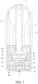
FIG. 3 is a cross-sectional diagram of a vaporizer according to an embodiment of this application; -
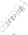
FIG. 4 is an exploded diagram from a perspective of a vaporizer according to an embodiment of this application; -
FIG. 5 is an exploded diagram from another perspective of a vaporizer according to an embodiment of this application; -
FIG. 6 is a three-dimensional diagram of a fixing bracket according to an embodiment of this application; -
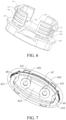
FIG. 7 is a three-dimensional diagram from a perspective of a base according to an embodiment of this application; -
FIG. 8 is a three-dimensional diagram from another perspective of a base according to an embodiment of this application; -
FIG. 9 is a three-dimensional diagram of a sealing gasket according to an embodiment of this application; -
FIG. 10 is a three-dimensional diagram of a base and a sealing gasket after assembly according to an embodiment of this application; and -
FIG. 11 is a three-dimensional diagram of a base according to another embodiment of this application. - For ease of understanding of this application, this application is described below in more detail with reference to accompanying drawings and specific implementations.
- It should be noted that all the directional indicators (for example, upper, lower, left, right, front, rear, horizontal, and vertical) in embodiments of this application are merely used to explain a relative location relationship, motion statuses, and the like between components in a specific state (as shown in the accompanying drawings). If the specific state changes, the directional indicator correspondingly changes, the "connection" may be direct connection or indirect connection, and the "disposed", "disposed at", and "set at" may be directly or indirectly disposed.
- In addition, descriptions involving "first" and "second" in this application are merely used for a purpose of description, and shall not be understood as an indication or implication of relative importance or implicit indication of a quantity of indicated technical features. Therefore, features defining "first" and "second" can explicitly or implicitly include at least one of the features.
- This application provides an aerosol generation device, referring to
FIG. 1 , including avaporizer 100 and apower supply device 200. Thevaporizer 100 stores an aerosol-forming substrate and can vaporize the aerosol-forming substrate to form an aerosol. Thepower supply device 200 supplies power to thevaporizer 100 for driving. Thevaporizer 100 and thepower supply device 200 may be fixedly connected or detachably connected. Thevaporizer 100 provided in this application is detachably connected to thepower supply device 200, such as magnetic connection, snap-fit connection, and the like. The specific connection method is not limited. Thepower supply device 200 can be divided into two parts in a longitudinal direction. Afirst part 201 can accommodate at least a part of a surface of thevaporizer 100, and asecond part 202 can accommodate other components that constitute the power supply device, such as a battery, a control module, a charging module, and the like. - As shown in
FIG. 2 andFIG. 4 , thevaporizer 100 includes ahousing 10. Thehousing 10 is provided with a proximal end and a distal end that are longitudinally opposite. The proximal end is provided with a suction nozzle opening 11, and the aerosol can be output to the outside of thehousing 10 through the suction nozzle opening 11. The distal end is open to facilitate mounting of other functional components of thevaporizer 100 inside thehousing 10. Aliquid storage cavity 12 of a liquid storage substrate for storing a liquid substrate and avaporization component 20 for vaporizing the liquid substrate to form an aerosol are provided in thehousing 10. - Referring to
FIG. 3 to FIG. 5 , thevaporization component 20 includes aporous body 21 and aheating element 22 for heating the liquid substrate absorbed by theporous body 21. Theporous body 21 may be made of a hard capillary structure such as porous ceramic, porous glass ceramic, or porous glass. In this application, a porous ceramic material is preferred and is generally formed by high-temperature sintering of aggregate, a binder, a pore-forming agent, and other components. The material has a large quantity of pore structures inside that are in communication with each other and in communication with a surface of the material. The liquid substrate can penetrate into the interior through the surface of theporous body 21 and be vaporized by theheating element 42 to form the aerosol. Theheating element 22 may be a heating coating, a heating sheet, or a heating mesh. The heating coating may include, but is not limited to, an electromagnetic induction heating coating, an infrared induction heating coating, and the like. The heating sheet or the heating mesh is embedded and fixed in the surface of the porous body. In this application, preferably, the heating element is formed on the surface of theporous body 21 by mixing conductive raw material powder and printing auxiliaries into paste and sintering after printing, and has effects of high vaporizing efficiency, less heat loss, and preventing or greatly reducing dry burning. In some embodiments, theheating element 22 may be made of a material such as stainless steel, nickel chromium alloy, iron chromium aluminum alloy, or metal titanium. - A shape of the
porous body 21 is constructed into a roughly block-shaped structure in this embodiment. A top surface is roughly H-shaped, a left side surface and a right side surface are roughly U-shaped, a front side surface, a rear side surface, and a bottom surface are square, and agroove 23 is formed in the middle. Thegroove 23 can be used to temporarily store the liquid substrate and increase a diffusion speed of the liquid substrate inside theporous body 21. The specific shape of theporous body 21 can be changed according to needs and is not limited to a specific shape. A bottom surface of thegroove 23 forms aliquid absorbing surface 211. Theheating element 22 is formed on the bottom surface of theporous body 21, and the bottom surface becomes avaporization surface 212. - The
housing 10 is further provided with a fixingbracket 30 for fixing thevaporization component 20 inside thehousing 10, and a sealingsleeve 40 for sealing theliquid storage cavity 12. Referring toFIG. 4 to FIG. 6 , the fixingbracket 30 is provided with anaccommodating portion 31, and theaccommodating portion 31 is provided with anaccommodating cavity 311. At least a part of the surface of thevaporization component 20 can be fixedly held inside theaccommodating cavity 311. An end of the fixingbracket 30 that faces theliquid storage cavity 12 is further provided with adiversion portion 32. Thediversion portion 32 is provided with at least one firstliquid guiding hole 321 in fluid communication with theliquid storage cavity 12. The sealingsleeve 40 is sleeved on an outer wall of thediversion portion 32. A cross-section of the sealingsleeve 40 that is perpendicular to an axial direction of thehousing 10 matches a cross-section of the liquid storage cavity that is perpendicular to the axial direction of thehousing 10, so that the sealingsleeve 40 completely seals theliquid storage cavity 12 to prevent the liquid substrate from leaking downward. The sealingsleeve 40 is also provided with at least one secondliquid guiding hole 41 that is in communication with the firstliquid guiding hole 321. Preferably, two firstliquid guiding holes 321 are provided on a left side and a right side of thediversion portion 32, and two secondliquid guiding holes 41 are provided on the sealingsleeve 40 at corresponding positions, and the cross-sections of the firstliquid guiding holes 321 and the secondliquid guiding holes 41 that are perpendicular to the axial direction of thehousing 10 have a same size and shape, to improve the transfer efficiency of the liquid substrate. - In order to enhance the sealing connection between contact surfaces of the
accommodating portion 31 of the fixing bracket and theporous body 21 of the vaporization component, a sealingmember 50 is further provided between the two contact surfaces. The sealingmember 50 is made of a flexible silicone material, so that the fixingbracket 30 and the surface of theporous body 21 are tightly fixed. Further, the sealingmember 50 is provided with a thirdliquid guiding hole 51 at a position opposite to the firstliquid guiding hole 321. A quantity of thirdliquid guiding holes 51 is the same as a quantity of firstliquid guiding holes 321 and a quantity of second liquid guiding holes 41. The specific quantity can be adjusted and designed according to transfer rate requirements of the liquid substrate, and is not limited herein. The thirdliquid guiding hole 51 is in longitudinal communication with thegroove 23 in the middle of theporous body 21. A plurality of convex ribs are provided on an outer surface of the sealingmember 50. The convex ribs can strengthen the fixed connection between the sealingmember 50 and an inner wall of the fixingbracket 30. - Referring to
FIG. 3 to FIG. 5 , thehousing 10 is further provided with anair outlet pipe 13. An air outlet end of theair outlet pipe 13 is in communication with thesuction nozzle opening 11. The aerosol formed through vaporization performed by thevaporization component 20 can be output to the outside of thehousing 10 through theair outlet pipe 13. Theair outlet pipe 13 is located in the middle of theliquid storage cavity 12 and can be formed by extending at least a part of an inner wall surface of thehousing 10 longitudinally. An air inlet end of theair outlet pipe 13 longitudinally abuts against the sealingsleeve 40. The sealingsleeve 40 is provided with a firstair outlet hole 42 at a corresponding position. Thediversion portion 32 of the fixing bracket is provided with a secondair outlet hole 322 at a corresponding position. Preferably, since the air outlet pipe is located in the middle of theliquid storage cavity 12, the firstair outlet hole 42 is located between the two secondliquid guiding holes 41, and the secondair outlet hole 322 is located between the two first liquid guiding holes 321. Theair outlet pipe 13, the firstair outlet hole 42, and the secondair outlet hole 322 are in longitudinal communication along thehousing 10 to improve the output efficiency of the aerosol. - The
porous body 21 of the vaporization component is fixed in theaccommodating portion 31. Theaccommodating cavity 311 of theaccommodating portion 31 is defined by atop surface 312, afirst side wall 313, and asecond side wall 314. Thefirst side wall 313 and thesecond side wall 314 are spaced apart, and afirst gap 331 and asecond gap 332 are formed in the middle. Thefirst gap 331 is disposed opposite to thesecond gap 332. The aerosol formed through vaporization performed by theheating element 22 can enter the secondair outlet hole 332 and the firstair outlet hole 42 through thefirst gap 331 and/or thesecond gap 332, and then enter theair outlet pipe 13. - Referring to
FIG. 4 ,FIG. 5 ,FIG. 7 , andFIG. 8 , anopen end 14 of thehousing 10 is covered with abase 60. Thebase 60 is provided with abottom surface 61 covering theopen end 12, and abody portion 62. At least onefirst buckle 621 is provided on an outer wall surface of thebody portion 62, and at least onefirst gap 15 is provided on thehousing 10. Thefirst buckle 621 and thefirst gap 15 match each other, so that thebase 60 and thehousing 10 are fixedly connected. Preferably, fourfirst buckles 621 are provided at intervals on the outer wall of thebody portion 62, and fourfirst gaps 15 are provided correspondingly at intervals on thehousing 10. - The
base 60 is further provided with afirst support arm 631 and asecond support arm 632. Thefirst support arm 631 and thesecond support arm 632 are disposed opposite to each other and located above thebody portion 62. Thebase 60 and the fixingbracket 30 are fixedly connected. Specifically, referring toFIG. 4 to FIG. 6 , parts of outer wall surfaces on two sides of thediversion portion 31 protrude outward to formflanges 323. A firstaccommodating region 341 is formed between theleft flange 323 and thefirst side wall 313. A secondaccommodating region 342 is formed between the right flange and thesecond side wall 314. A part of thefirst support arm 631 can be accommodated in the firstaccommodating region 341, and a part of thesecond support arm 632 can be accommodated in the secondaccommodating region 342. Further, asecond buckle 35 is provided on an outer wall surface at a lower end of each of thefirst side wall 313 and thesecond side wall 314, and asecond gap 64 is provided on each of thefirst support arm 631 and thesecond support arm 632. The second buckles 35 and thesecond gaps 64 provided on the left side and the right side are fixedly connected, so that thebase 60 and the fixingbracket 30 are tightly connected. Further, a plurality of capillary grooves are transversely provided on thefirst side wall 313 and thesecond side wall 314 of the fixing bracket, and the outer wall surfaces of thefirst support arm 631 and thesecond support arm 632 of the base. The capillary grooves form a stacked structure, which can buffer the liquid substrate, and prevent the liquid substrate from further leaking downward, to further improve a leak-proof function of theentire vaporizer 100. - The
vaporization component 20 is accommodated in theaccommodating cavity 311 of the fixing bracket. Thevaporization surface 212 is disposed directly facing thebody portion 62 of the base. Thevaporization surface 212 and thebody portion 62 jointly define thevaporization cavity 24. Thebody portion 62 defines a receivingcavity 622. At least a part of thebase 60 defines anair inlet 80 for entry of external air. Specifically, at least a part of thebottom surface 61 of the base is recessed inward to form afirst groove 65, and thefirst groove 65 defines theair inlet 80. Theair inlet 80 extends transversely in a short axis direction of thehousing 10. Two electrode mounting holes 66 are provided on two sides of theair inlet 80, namely, a positiveelectrode mounting hole 661 and a negativeelectrode mounting hole 662 respectively. Theair inlet 80 is in transverse communication with each of the positiveelectrode mounting hole 661 and the negativeelectrode mounting hole 662. Twoelectrodes 90 are further provided in thehousing 10, namely, apositive electrode 901 and anegative electrode 902 respectively. One end of theelectrode 90 is connected to theheating element 22 on the vaporization component, and the other end is connected to theelectrode 90 in thepower supply device 200 to provide electric energy for theheating element 22. Thepositive electrode 901 is mounted in the positiveelectrode mounting hole 661, and thenegative electrode 902 is mounted in the negativeelectrode mounting hole 662. In addition, the two electrode mounting holes 66 are both outward expanded holes, that is, hole diameters of the end portions of the two electrode mounting holes 66 are greater than a diameter of the longitudinally extending hole, so that athird airflow channel 81 is formed between the electrode mounting hole 66 and theelectrode 90. Thethird airflow channel 81 is disposed around theelectrode 90 and in communication with the transversely extendingair inlet 80. - Referring to
FIG. 3 andFIG. 8 , on two sides of theair inlet 80, at least a part of thebottom surface 61 is recessed to form two circularsecond grooves 67. A bottom end of theelectrode 90 is provided with a fixingend 91, and an outer diameter of the fixingend 91 is greater than the longitudinally extending outer diameter of thebody portion 92 of the electrode. The fixingend 91 is fixed in thesecond groove 67, and the electrode mounting hole 66 is located on thesecond groove 67. At least a part of the surface of thesecond groove 67 is recessed inward to form athird groove 68. Thethird groove 68 defines asecond airflow channel 82. Thesecond airflow channel 82 extends transversely in the short axis direction of thehousing 10 and is located on a straight line on which theair inlet 80 extends transversely. An air inlet end of thesecond airflow channel 82 is in communication with thethird airflow channel 81, and external air can enter thethird airflow channel 81 in the short axis direction of thehousing 10 through theair inlet 80, and then enter thesecond airflow channel 82. - The
housing 10 is further provided with at least onefirst airflow channel 83 that connects thevaporization cavity 24 to thesecond airflow channel 82. Thefirst airflow channel 83 extends in a direction from theair inlet 80 toward thevaporization cavity 24. Further, avent column 69 is provided close to each of two sides in thebody portion 62. The left andright vent columns 69 define thefirst airflow channel 83, and an air inlet end of thevent column 69 is transversely covered by the fixingend 91 of the electrode column. The external air passes through theair inlet 80, bypasses thethird airflow channel 81, enters thesecond airflow channel 82, circulates transversely, enters thefirst airflow channel 83, circulates longitudinally, and enters thevaporization cavity 24. Since thesecond airflow channels 82 are disposed on two sides of thebase 60 and are at a specific height from a bottom surface of the receivingcavity 622, it is difficult for the condensate formed when the aerosol in thevaporization cavity 24 cools to enter thesecond airflow channel 82 and leak outward. - The external airflow enters the
vaporization cavity 24 from thefirst airflow channels 83 on two sides, which easily causes the temperatures on two sides of theheating element 24 to be low. A region in the middle of theheating element 24 has a higher temperature because it is difficult for the external airflow to converge. Because a main component of the liquid substrate is glycerol, abnormal decomposition of the glycerol at a high temperature produces formaldehyde, which affects the environmental testing effect of the entire device. In order to avoid the production of the formaldehyde, a sealinggasket 70 is provided in the receivingcavity 622 of the body portion. Referring toFIG. 3 to FIG. 10 , specifically, the sealinggasket 70 is disposed above the air outlet end of thefirst airflow channel 83 and substantially covers the entire receivingcavity 622. Avent hole 71 is disposed in the middle of the sealinggasket 70, and thevent hole 71 is disposed directly facing theheating element 22, so that the external airflow on two sides of thefirst airflow channel 83 converges and enters thevaporization cavity 24 through thevent hole 71. In addition, the air outlet end of thevent hole 71 is higher than the surrounding surface and closer to thevaporization surface 212, so as to improve the vaporization efficiency. - More specifically, two through
holes 72 are further provided on two sides of thevent hole 71 to make it convenient for twoelectrodes 90 to axially pass through the sealinggasket 70 to be connected to thevaporization component 20, and a plane on which the two throughholes 72 are located is higher than a plane on which thevent hole 71 is located, so that a plane around thevent hole 71 forms afirst buffer region 73 for the condensate. Further, a region between the sealinggasket 70 and the base 60 forms asecond buffer region 74 for the condensate. In order to help the condensate enter thefirst buffer region 73, thebody portion 62 of the base and the sealinggasket 70 are each provided with adiversion portion 16. Specifically, the inner wall surface of thebody portion 62 that faces two sides of thefirst buffer region 73 is provided with a first diversioninclined plane 161, the inner wall surface of the sealinggasket 70 that faces the two sides of thefirst buffer region 73 is further provided with a second diversioninclined plane 162, and the second diversioninclined plane 162 follows the first diversioninclined plane 161. The condensate in thevaporization cavity 24 can flow into the second diversioninclined plane 162 along the first diversioninclined plane 161 and then enter thefirst buffer region 73. When the liquid buffered in thefirst buffer region 73 is excessive, the liquid can flow into thesecond buffer region 74 through thevent hole 71. In addition, since a bottom end surface of thesecond buffer region 74 defined by thebody portion 62 is completely closed, and the air outlet ends of thefirst airflow channels 83 on two sides are close to the bottom surface of the sealinggasket 70, the condensate cannot enter thefirst airflow channels 83 on the two sides. The inner walls on two sides of the second diversioninclined plane 162 are further provided with adiversion groove 163 that is in longitudinal communication with thesecond buffer region 74. The wall surfaces on the two sides of the sealinggasket 70 are symmetrically provided with two second diversion inclinedplanes 162 and fourdiversion grooves 163, so that the condensate in thevaporization cavity 24 or the leaked liquid substrate can be smoothly introduced into thefirst buffer region 73 and thesecond buffer region 74. - This application further provides another preferred implementation solution. Referring to
FIG. 11 , different from the foregoing embodiment, afirst airflow channel 83 is jointly defined by ahousing 10 and abase 20, and a bottom end of thefirst airflow channel 83 extends longitudinally and passes through abottom surface 61 of the base. The external air can enter through asecond air inlet 831 on a bottom end surface of thefirst airflow channel 83, or can enter through asecond airflow channel 82 that is in transverse communication with thefirst airflow channel 83, and can converge and enter thefirst airflow channel 83. When thevaporizer 100 is connected to thepower supply device 200, thesecond air inlet 831 of thefirst airflow channel 83 is disposed on thebottom surface 61 and therefore can be covered and closed by a physical portion on a connection end surface of thepower supply device 200. An airflow sensing switch in thepower supply device 200 senses changes in an inhaling air pressure in thevaporizer 100 through an air pressure detection channel connected to theair inlet 80 to control the working state of the aerosol generation device. - In the foregoing
vaporizer 100, since theair inlet 80 is completely isolated from thefirst buffer region 73 and thesecond buffer region 74, the condensate cannot leak to the outside of thevaporizer 100 through theair inlet 80. The external air flows transversely into thefirst airflow channels 83 on the two sides through theair inlet 80. Further, in order to improve the overall vaporization effect in thevaporization cavity 24 and prevent the local temperature on thevaporization surface 212 from being too high to generate formaldehyde, gas inside thefirst airflow channels 83 on two sides converges and enters thevaporization cavity 24 through thevent hole 71 directly facing theheating element 22, and the external airflow diffuses evenly into theentire vaporization cavity 24, without causing the local temperature on thevaporization surface 212 to be too high, thereby greatly reducing the generation of excessive vaporization products such as formaldehyde, and improving the vaporization efficiency and the environmental testing effect of theentire vaporizer 100. - This written description uses examples to disclose this application, including the best mode, and further enables a person skilled in the art to make and use this application. The patentable scope of this application is defined by the claims, and may include other examples that can be conceived by a person skilled in the art. Such other examples are intended to be within the scope of the claims if such other examples have structural elements that do not differ from the literal language of the claims, or if such other examples include equivalent structural elements that do not differ materially from the literal language of the claims. To an extent that inconsistency would not be caused, all citations cited herein are hereby incorporated by reference.
Claims (11)
- A vaporizer, comprising:a housing provided with an open end, wherein a liquid storage cavity for storing a liquid substrate and a vaporization component for vaporizing the liquid substrate to form an aerosol are provided in the housing; anda base, connected to the open end of the housing, whereinat least a part of the base defines an air inlet for entry of external air,the base and the vaporization component jointly define a vaporization cavity, and the vaporization cavity and the air inlet are in fluid communication through an airflow channel, whereinthe airflow channel comprises at least one first airflow channel and at least one second airflow channel, the first airflow channel extends in a direction from the air inlet toward the vaporization cavity, and the second airflow channel extends on the base and is roughly perpendicular to the extending direction of the first airflow channel.
- The vaporizer according to claim 1, wherein a sealing gasket is provided in the base, the sealing gasket has a vent hole, and the vent hole connects the first airflow channel to the vaporization cavity; and
the vaporization component comprises a porous body and a heating element, and the vent hole is disposed directly facing the heating element. - The vaporizer according to claim 2, wherein at least a part of the sealing gasket defines at least one buffer region capable of storing a condensate; and at least one diversion portion is provided on the sealing gasket, and the condensate is capable of entering the buffer region along the diversion portion.
- The vaporizer according to claim 1, wherein the base is provided with a bottom surface, and the air inlet is defined by a first groove formed by recessing at least a part of the bottom surface.
- The vaporizer according to claim 4, further comprising an electrode that is connected to the vaporization component and supplies power to the vaporization component, wherein
two electrode mounting holes are provided on the bottom surface, wherein a hole diameter of an end portion of at least one electrode mounting hole is greater than an outer diameter of the electrode, to form a third airflow channel between the electrode and the electrode mounting hole, and the third airflow channel connects the air inlet to the second airflow channel. - The vaporizer according to claim 5, wherein the electrode has a fixing portion mounted on the bottom surface, and at least a part of the fixing portion covers an air inlet end of the first airflow channel.
- The vaporizer according to claim 6, wherein at least a part of the bottom surface is recessed to form two second grooves, and the fixing portion is capable of being fixedly mounted in the second grooves; and
the second grooves are located on two sides of the air inlet. - The vaporizer according to claim 7, wherein at least a part of a surface of the second groove is recessed to form a third groove, and the third groove defines the second airflow channel.
- The vaporizer according to claim 8, wherein the second airflow channel is on a straight line on which the air inlet extends transversely in a short axis direction of the housing.
- The vaporizer according to claim 1, wherein the first airflow channel is located on the base or is jointly defined by the housing and the base.
- An aerosol generation device, comprising the vaporizer according to any one of claims 1 to 10, and a power supply device for supplying power to the vaporizer for driving.
Applications Claiming Priority (2)
| Application Number | Priority Date | Filing Date | Title |
|---|---|---|---|
| CN202121080033.3U CN215958369U (en) | 2021-05-20 | 2021-05-20 | Atomizer and aerosol-generating device |
| PCT/CN2022/093627 WO2022242691A1 (en) | 2021-05-20 | 2022-05-18 | Atomizer and aerosol generating device |
Publications (2)
| Publication Number | Publication Date |
|---|---|
| EP4353104A1 true EP4353104A1 (en) | 2024-04-17 |
| EP4353104A4 EP4353104A4 (en) | 2024-10-16 |
Family
ID=80574446
Family Applications (1)
| Application Number | Title | Priority Date | Filing Date |
|---|---|---|---|
| EP22804011.9A Pending EP4353104A4 (en) | 2021-05-20 | 2022-05-18 | ATOMIZER AND AEROSOL GENERATING DEVICE |
Country Status (4)
| Country | Link |
|---|---|
| US (1) | US20240237747A1 (en) |
| EP (1) | EP4353104A4 (en) |
| CN (1) | CN215958369U (en) |
| WO (1) | WO2022242691A1 (en) |
Families Citing this family (4)
| Publication number | Priority date | Publication date | Assignee | Title |
|---|---|---|---|---|
| CN215958369U (en) * | 2021-05-20 | 2022-03-08 | 深圳市合元科技有限公司 | Atomizer and aerosol-generating device |
| CN218219129U (en) * | 2022-08-08 | 2023-01-06 | 深圳市基克纳科技有限公司 | A condensate collection component and a heat-not-burn device |
| CN217885111U (en) * | 2022-08-12 | 2022-11-25 | 深圳市卓尔悦电子科技有限公司 | Atomization device and aerosol generation device |
| CN116114921A (en) * | 2022-12-15 | 2023-05-16 | 惠州市新泓威科技有限公司 | Electronic cigarette atomizing device and electronic cigarette atomizer thereof |
Family Cites Families (13)
| Publication number | Priority date | Publication date | Assignee | Title |
|---|---|---|---|---|
| CN208286373U (en) * | 2018-05-14 | 2018-12-28 | 深圳麦克韦尔股份有限公司 | Electronic cigarette and its atomizer |
| EP3847914B1 (en) * | 2018-09-05 | 2025-10-29 | Shenzhen Smoore Technology Limited | Atomizer and electronic atomization device |
| WO2020115322A1 (en) * | 2018-12-07 | 2020-06-11 | Philip Morris Products S.A. | An atomiser and an aerosol-generating system comprising an atomiser |
| CN210275886U (en) * | 2019-07-19 | 2020-04-10 | 常州市派腾电子技术服务有限公司 | Atomizing components, atomizers and aerosol generating devices |
| CN211861815U (en) * | 2019-11-25 | 2020-11-06 | 深圳麦克韦尔科技有限公司 | Atomizer and electronic atomization device |
| CN211482973U (en) * | 2019-11-26 | 2020-09-15 | 深圳市合元科技有限公司 | Atomizing components and electronic cigarettes |
| CN211910517U (en) * | 2020-01-03 | 2020-11-13 | 深圳市合元科技有限公司 | Atomizers and Electronic Cigarettes |
| CN212911688U (en) * | 2020-02-10 | 2021-04-09 | 常州市派腾电子技术服务有限公司 | Atomizer and its aerosol generating device |
| CN212464889U (en) * | 2020-07-30 | 2021-02-05 | 深圳市吉迩科技有限公司 | Buffering and leak protection air flue and electron cigarette |
| CN112021659B (en) * | 2020-09-16 | 2025-03-18 | 深圳麦克韦尔科技有限公司 | Atomizer and electronic atomization device |
| CN114504127A (en) * | 2020-11-17 | 2022-05-17 | 深圳市合元科技有限公司 | Atomizer and electronic atomization device |
| CN112716039B (en) * | 2020-12-30 | 2025-11-18 | 江门摩尔科技有限公司 | An atomizer and an electronic atomizing device |
| CN215958369U (en) * | 2021-05-20 | 2022-03-08 | 深圳市合元科技有限公司 | Atomizer and aerosol-generating device |
-
2021
- 2021-05-20 CN CN202121080033.3U patent/CN215958369U/en active Active
-
2022
- 2022-05-18 EP EP22804011.9A patent/EP4353104A4/en active Pending
- 2022-05-18 WO PCT/CN2022/093627 patent/WO2022242691A1/en not_active Ceased
- 2022-05-18 US US18/562,628 patent/US20240237747A1/en active Pending
Also Published As
| Publication number | Publication date |
|---|---|
| WO2022242691A1 (en) | 2022-11-24 |
| EP4353104A4 (en) | 2024-10-16 |
| US20240237747A1 (en) | 2024-07-18 |
| CN215958369U (en) | 2022-03-08 |
Similar Documents
| Publication | Publication Date | Title |
|---|---|---|
| US20240237747A1 (en) | Vaporizer and aerosol generation device | |
| US20230389615A1 (en) | Vaporizer and electronic vaporization device | |
| US20250098773A1 (en) | Vaporizer and electronic vaporization device | |
| JP2023178218A (en) | Heat generating module, atomization assembly, and electronic atomization device | |
| US20250098751A1 (en) | Electronic aerosol generation device and atomizer thereof | |
| CN115413828A (en) | Atomization structure, atomizer and electronic atomization device | |
| CN217826755U (en) | Antiseep atomizer and electronic atomization device | |
| CN217906282U (en) | Heating element, atomizing core and aerosol generating device | |
| US20240237746A1 (en) | Electronic vaporization device and vaporizer thereof | |
| CN216059195U (en) | Electronic atomizer | |
| US20230097171A1 (en) | Electronic vaporization device and vaporizer thereof | |
| CN218043796U (en) | Heating module, atomizing component and electronic atomizer | |
| CN214710348U (en) | Electronic atomization device, atomizer and base thereof | |
| CN223247559U (en) | Atomizing subassembly, electron atomizer and electron atomizing device | |
| CN220831935U (en) | Atomizing device and atomizing equipment | |
| CN222031444U (en) | Atomization components and atomization devices | |
| CN221599203U (en) | Electronic atomizing device | |
| CN222466044U (en) | Atomizer and electronic atomization device | |
| CN219422219U (en) | Atomizing device | |
| CN222888603U (en) | Leak-proof electronic atomizer and electronic atomizing device | |
| CN221785331U (en) | Atomizing device | |
| US20250359595A1 (en) | Atomizer and electronic atomization device | |
| CN220458619U (en) | Atomizer and electronic atomization device comprising same | |
| CN221228731U (en) | Cartridge and electronic pumping device | |
| RU2808668C1 (en) | Air intake device with two channels for air supply, power supply device and device for aerosol generation |
Legal Events
| Date | Code | Title | Description |
|---|---|---|---|
| STAA | Information on the status of an ep patent application or granted ep patent |
Free format text: STATUS: THE INTERNATIONAL PUBLICATION HAS BEEN MADE |
|
| PUAI | Public reference made under article 153(3) epc to a published international application that has entered the european phase |
Free format text: ORIGINAL CODE: 0009012 |
|
| STAA | Information on the status of an ep patent application or granted ep patent |
Free format text: STATUS: REQUEST FOR EXAMINATION WAS MADE |
|
| 17P | Request for examination filed |
Effective date: 20231215 |
|
| AK | Designated contracting states |
Kind code of ref document: A1 Designated state(s): AL AT BE BG CH CY CZ DE DK EE ES FI FR GB GR HR HU IE IS IT LI LT LU LV MC MK MT NL NO PL PT RO RS SE SI SK SM TR |
|
| DAV | Request for validation of the european patent (deleted) | ||
| DAX | Request for extension of the european patent (deleted) | ||
| REG | Reference to a national code |
Ref country code: DE Ref legal event code: R079 Free format text: PREVIOUS MAIN CLASS: A24F0040480000 Ipc: A24F0040485000 |
|
| STAA | Information on the status of an ep patent application or granted ep patent |
Free format text: STATUS: EXAMINATION IS IN PROGRESS |
|
| A4 | Supplementary search report drawn up and despatched |
Effective date: 20240913 |
|
| RIC1 | Information provided on ipc code assigned before grant |
Ipc: A24F 40/10 20200101ALI20240909BHEP Ipc: A24F 40/485 20200101AFI20240909BHEP |
|
| 17Q | First examination report despatched |
Effective date: 20240925 |