EP4351277A1 - Oven - Google Patents
Oven Download PDFInfo
- Publication number
- EP4351277A1 EP4351277A1 EP22200315.4A EP22200315A EP4351277A1 EP 4351277 A1 EP4351277 A1 EP 4351277A1 EP 22200315 A EP22200315 A EP 22200315A EP 4351277 A1 EP4351277 A1 EP 4351277A1
- Authority
- EP
- European Patent Office
- Prior art keywords
- oven
- annular
- annular groove
- front frame
- door cover
- Prior art date
- Legal status (The legal status is an assumption and is not a legal conclusion. Google has not performed a legal analysis and makes no representation as to the accuracy of the status listed.)
- Pending
Links
Images



Classifications
-
- H—ELECTRICITY
- H05—ELECTRIC TECHNIQUES NOT OTHERWISE PROVIDED FOR
- H05B—ELECTRIC HEATING; ELECTRIC LIGHT SOURCES NOT OTHERWISE PROVIDED FOR; CIRCUIT ARRANGEMENTS FOR ELECTRIC LIGHT SOURCES, IN GENERAL
- H05B6/00—Heating by electric, magnetic or electromagnetic fields
- H05B6/64—Heating using microwaves
- H05B6/6414—Aspects relating to the door of the microwave heating apparatus
-
- A—HUMAN NECESSITIES
- A47—FURNITURE; DOMESTIC ARTICLES OR APPLIANCES; COFFEE MILLS; SPICE MILLS; SUCTION CLEANERS IN GENERAL
- A47J—KITCHEN EQUIPMENT; COFFEE MILLS; SPICE MILLS; APPARATUS FOR MAKING BEVERAGES
- A47J37/00—Baking; Roasting; Grilling; Frying
- A47J37/06—Roasters; Grills; Sandwich grills
- A47J37/0623—Small-size cooking ovens, i.e. defining an at least partially closed cooking cavity
- A47J37/0664—Accessories
-
- A—HUMAN NECESSITIES
- A47—FURNITURE; DOMESTIC ARTICLES OR APPLIANCES; COFFEE MILLS; SPICE MILLS; SUCTION CLEANERS IN GENERAL
- A47J—KITCHEN EQUIPMENT; COFFEE MILLS; SPICE MILLS; APPARATUS FOR MAKING BEVERAGES
- A47J37/00—Baking; Roasting; Grilling; Frying
- A47J37/06—Roasters; Grills; Sandwich grills
- A47J37/0623—Small-size cooking ovens, i.e. defining an at least partially closed cooking cavity
-
- F—MECHANICAL ENGINEERING; LIGHTING; HEATING; WEAPONS; BLASTING
- F24—HEATING; RANGES; VENTILATING
- F24C—DOMESTIC STOVES OR RANGES ; DETAILS OF DOMESTIC STOVES OR RANGES, OF GENERAL APPLICATION
- F24C15/00—Details
- F24C15/02—Doors specially adapted for stoves or ranges
- F24C15/021—Doors specially adapted for stoves or ranges sealings for doors or transparent panel
-
- F—MECHANICAL ENGINEERING; LIGHTING; HEATING; WEAPONS; BLASTING
- F24—HEATING; RANGES; VENTILATING
- F24C—DOMESTIC STOVES OR RANGES ; DETAILS OF DOMESTIC STOVES OR RANGES, OF GENERAL APPLICATION
- F24C7/00—Stoves or ranges heated by electric energy
- F24C7/02—Stoves or ranges heated by electric energy using microwaves
-
- H—ELECTRICITY
- H05—ELECTRIC TECHNIQUES NOT OTHERWISE PROVIDED FOR
- H05B—ELECTRIC HEATING; ELECTRIC LIGHT SOURCES NOT OTHERWISE PROVIDED FOR; CIRCUIT ARRANGEMENTS FOR ELECTRIC LIGHT SOURCES, IN GENERAL
- H05B6/00—Heating by electric, magnetic or electromagnetic fields
- H05B6/64—Heating using microwaves
- H05B6/76—Prevention of microwave leakage, e.g. door sealings
- H05B6/763—Microwave radiation seals for doors
Definitions
- the present invention relates to an oven, in particular an oven having a microwave heating function.
- microwave ovens typically comprise a box-shaped oven body including: an oven cavity, which is adapted to contain food products, e.g. in solid and/or liquid form, to be heated and is provided with a front opening allowing to access the inside space of the oven cavity; and a perimeter front frame, which is carried by the oven cavity and surrounds seamlessly the front opening of the oven cavity.
- an oven cavity which is adapted to contain food products, e.g. in solid and/or liquid form, to be heated and is provided with a front opening allowing to access the inside space of the oven cavity
- a perimeter front frame which is carried by the oven cavity and surrounds seamlessly the front opening of the oven cavity.
- microwave ovens usually comprise an oven door that is carried in an angular moveable manner by the oven body and is movable from and toward a closed position, within which the oven door closes the front opening of the oven cavity.
- a tight annular gap or slot may be defined on the oven body, between the perimeter front frame and the oven cavity.
- the annular gap may seamlessly surround the front opening of the oven cavity and may accommodate an annular gasket.
- the annular gasket may be firmly attached to the oven body, inside the annular gap defined between the perimeter front frame and the oven cavity.
- the above-mentioned annular gasket may comprise a first stiff end portion that is hook-like shaped, is made at least partially by a metal material, and engages to a protruding lip of the perimeter front frame of the oven body, inside the annular gap surrounding the front opening.
- the above-mentioned annular gasket may comprise a second flexible end portion, opposite to the first end portion, which is made by a polymeric material, protrudes cantilevered from the perimeter front frame of the oven body and is adapted to be arranged in abutment against the oven door when this latter is in the closed position, in order to seal the oven cavity.
- the oven door may have a box-like structure and may comprise an inner door cover facing the oven body and an outer front glass panel carried by the inner door cover, on the opposite side with respect to the oven body.
- the inner door cover is adapted to be arranged into abutment against the annular gasket carried by the oven body when the oven door is in the closed position.
- Aim of the present invention is to solve the above-mentioned needs in a cost effective and optimized manner.
- an oven preferentially an oven having a microwave heating function, according to the respective independent claim.
- an oven for the thermal treatment of an item preferentially a food product, and preferentially having a microwave heating function.
- the oven comprises at least:
- the oven door comprises an inner door cover, which is adapted to be arranged skimming the perimeter front frame when the oven door is in the closed position and is provided with an annular groove extending on the surface of the inner door cover facing the front frame and accommodating the annular gasket.
- the oven door and the annular gasket carried by the oven door may be completely pre-assembled before reaching the product assembly line, with all the benefits that this entails.
- the presence of the annular groove in the inner door cover accommodating the annular gasket allows one to have a completely free design choice in deciding the position, the shape and the dimensions of these two components. In this way, it is possible to optimize the sealing performance of the oven door while keeping the annular gap between the inner door cover and the perimeter front frame as small as possible. This is particularly advantageous if the oven has a microwave heating function as the sealing performance does not compromise the microwave sealing performances of the wave choke system, which may be carried by the oven door.
- Another particular advantage of the oven according to the present invention is related to the enhanced cleanability and the improved aesthetic appearance of the oven, as the front surface of the oven body is smooth and homogeneous, and there are no gaps or crevices between the perimeter front frame and the oven cavity. In particular, this prevents parts of the items to deposit between the oven cavity and the perimeter front frame, making it much easier to clean the oven body of the oven.
- the inner door cover is formed as a single piece and comprises a rear wall that lies on a plane orthogonal to the reference axis and skims the perimeter front frame when the oven door is in the closed position; the annular groove extends on the rear wall of the inner door cover so as to surround seamlessly the front opening of the oven cavity when the oven door is in the closed position.
- annular groove may be specifically designed to accommodate the annular gasket.
- the annular gasket is provided with anchoring means that are configured to engage within the annular groove, in order to steadily retain the annular gasket inside the annular groove.
- the anchoring means improves the engagement and the positioning of the annular gasket inside the annular groove.
- the annular grove comprises: a first annular groove portion, which connects to the rear wall and delimits an opening of the annular groove allowing the annular gasket to be at least partially arranged within the annular groove; and a second annular groove portion, which connects to the first annular groove portion, on the opposite side with respect to the rear wall.
- the first annular groove portion is shaped so as to define a seat accommodating a portion of the annular gasket.
- the seat allows one to simplify and speed-up the insertion and the placement of the annular gasket inside the annular groove.
- the annular groove is provided with a plurality of cutouts that are formed in the second annular groove portion and are angularly spaced apart from one another along the annular groove.
- the cutouts allow the annular gasket to locally deform and expand inside the annular groove, so as to improve the engagement of the annular gasket inside the annular groove, in particular allowing to improve the fastening of the annular gasket within the annular groove.
- one is able to reach the annular gasket from below through the cutouts, in order to pull down and adjust the positioning of the annular gasket inside the annular groove.
- the annular gasket comprises: a first annular gasket portion, which is arranged at least partially within the first annular groove portion and protrudes cantilevered from the inner door cover, in order to abut against the perimeter front frame when the oven door is in the closed position; and a second annular gasket portion, which connects to the first annular gasket portion and is arranged within the second annular groove portion.
- the first annular gasket portion abutting against the perimeter front frame when the oven door is in the closed position seals the oven cavity against steam and/or thermal leakages.
- the second annular groove portion has a substantially U-shaped profile and comprises two facing sidewalls connected by a base wall.
- the annular groove is able to accommodate the annular gasket so that the gap between the oven door and the perimeter front frame is as small as possible when the oven door is in the closed position.
- the anchoring means of the annular gasket comprise a pair of laterally protruding lips, which protrude from opposite sides of the second annular gasket portion, in a direction transversal to annular gasket and/or towards the first annular portion, and are configured to engage with the sidewalls of the second annular groove portion.
- the two laterally protruding lips allow one to improve the fixing of the annular gasket inside the annular groove against both pulling and twisting in a simple and cost-effective manner.
- the laterally protruding lips are part of the annular gasket, which is produced as a single piece by means of an extrusion process.
- the first annular gasket portion is provided with a protruding annular lip configured to be pressed against the perimeter front frame when the oven door is in the closed position.
- the protruding annular lip may have a C-shaped profile.
- the protruding annular lip allows one to increase the sealing performances of the annular gasket against thermal and/or steam leakages.
- the C-shaped profile of the protruding annular lip of the first annular gasket portion creates an under pressure area when it is pressed against the perimeter front frame, so as to effectively seal the oven cavity against thermal and/or steam leakages.
- the annular gasket is formed as a single piece and is made out of a single polymeric material.
- the perimeter front frame is connected directly and seamlessly to the perimeter edge of the oven cavity that bounds the front opening, so that no gap or crevice is left between the perimeter edge of the oven cavity that bounds the front opening and the perimeter front frame.
- the aesthetic appearance and the cleanability of the oven are improved, as there are no more crevices or gaps between the annular perimeter edge of the oven cavity and the perimeter front frame.
- the assembly of the oven body is simplified, as the perimeter front frame may be directly fixed to the oven cavity, for instance by welding.
- the oven door further comprises:
- the wave choke system is provided with an annular portion that is configured to be arranged into abutment on the surface inner door cover opposite to the oven cavity, so as to be placed close to the perimeter front frame when the oven door is in the closed position.
- the metal wave choke system is provided with an annular slot, which is realized in the annular portion of the wave choke system, has a shape complementary to the shape of the annular groove of the inner door cover, and is configured to be arranged about the annular groove when the metal wave choke system is placed on the inner door cover, so that the annular portion of the wave choke system may enclose completely the annular groove and the annular gasket.
- the wave choke system is arranged as close as possible to the perimeter front frame when the oven door is closed.
- the wave choke system encloses completely the annular gasket, the annular gasket need not to comprise any metal part to stop microwaves propagation and it may be formed as a single piece completely in a polymeric material.
- number 1 denotes as a whole an oven, in particular an oven with a microwave heating function, for the thermal treatment, in particular for the heating, of items such as food products.
- Oven 1 may be a microwave oven or a multifunctional oven with a microwave heating function.
- the item to be thermally treated can be provided in solid and/or liquid form.
- the item to be thermally treated can be a food product such as meat, vegetables, beverages, soups, water and the like.
- microwave oven it is not limited to the microwave oven, but it may be related also to any kind of oven, preferentially of any kind of multifunctional oven with a microwave heating function, for instance a combined microwave and steam oven.
- Oven 1 comprises a box-shaped oven body 2 extending along a reference axis R.
- Oven body 2 includes an oven cavity 3, which is adapted to contain the item to be heated and is provided with a front opening 3a for the access to the inside volume of oven cavity 3. Additionally, oven body 2 includes a perimeter front frame 4, which is carried by the oven cavity 3 and encloses at least partially the front opening 3a of the oven cavity 3.
- reference axis R may be normal to front opening 3a.
- a depth of oven cavity 3 may be defined with respect to reference axis A.
- oven 1 comprises an oven door 6 (only partially shown in Figure 1 and 2 ), which is carried in an angular moveable manner by oven body 2 and is rotatable from and towards a closed position. In the closed position, oven door 6 is located into abutment against the perimeter front frame 4, so as to close the front opening 3a of the oven cavity 3.
- oven cavity 3 may have a substantially parallelepiped shape, and the front opening 3a of oven cavity 3 may have a substantially rectangular and/or quadratic shape.
- perimeter front frame 4 may have a shape complementary to the shape of the front opening 3a of oven cavity 3.
- perimeter front frame 4 may have an annular shape and it may surround seamlessly the front opening 3a of oven cavity 3.
- perimeter front frame 4 may be coupled directly and seamlessly to the annular perimeter edge of the oven cavity 3 that bounds the front opening 3a, so that no gap or crevice is left between the oven cavity 3 and the perimeter front frame 4.
- perimeter front frame 4 may be fixed to oven cavity 3 seamlessly along the entire annular perimeter edge that bounds the front opening 3a.
- front frame 4 may comprise a front annular wall 4a, which lies on a plane substantially orthogonal to the reference axis R and, in use, extends cantilevered outwardly from the annular perimeter edge of the oven cavity 3 that bounds the front opening 3a.
- perimeter front frame 4 may comprise an inner protruding flange 4b, which extends cantilevered from the inner annular edge of the front annular wall 4a, in a direction transversal to this latter.
- the protruding flange 4b may extend in a direction orthogonal to the front annular wall 4a, i.e. parallel to reference axis R.
- protruding flange 4b may surround seamlessly the front annular wall 4a.
- oven cavity 3 and perimeter front frame 4 are made of metal material, such as aluminum or the like.
- perimeter front frame 4 may have a monolithic structure and it may be realized starting from a single flat sheet of metal of adequate thickness.
- perimeter front frame 4 may be firmly fixed to oven cavity 3 by welding.
- protruding flange 4b of the perimeter front frame 4 may be fixed in direct contact and seamlessly with the annular perimeter edge of the oven cavity 3 that bounds the front opening 3a, so that no gap or crevice is left between the oven cavity 3 and the perimeter front frame 4 and the oven body 2 has a continuous and homogeneous front surface.
- oven door 6 may have a box-shaped structure and may comprise at least:
- the outer door cover may comprise a front glass panel, which may carry a door handle and may be carried by the inner door cover 7 by means of a pair of columnar fixing elements, in a manner known per se.
- inner door cover 7 is adapted to be arranged skimming the perimeter front frame 4 when oven door 6 is in the closed position, so as to define a narrow annular gap with this latter.
- the annular gap defined between the inner door cover 7 and the perimeter front frame 4, when oven door 6 is in the closed position may have a thickness t lower than 2 millimeters and more advantageously lower than or equal to 1 millimeter.
- the inner door cover 7 and/or the outer door cover may be shaped so as to define an inner cavity of the oven door 6.
- Inner glass panel 8 and metal wave choke system 9 may be arranged within this inner cavity.
- inner door cover 7 may have a monolithic structure and may be made of a polymeric material. In other words, inner door cover 7 may be formed as a single piece.
- inner door cover 7 may comprise a monolithic cup-shaped body 10.
- inner door cover 7 may comprise a rear wall 11 that lies on a plane orthogonal to reference axis R and skims the perimeter front frame 4 when oven door 6 is in the closed position. Additionally, inner door cover 7 may comprise a lateral wall 12 that extends cantilevered from the outer perimeter edge of the rear wall 11 in a transversal direction to this latter. Preferentially, lateral wall 12 may extend substantially orthogonal to the rear wall 11. Additionally, lateral wall 12 may have an annular shape and may surround substantially seamlessly the rear wall 11.
- the rear wall 11 of the inner door cover 7 may be provided with a central opening 13 with a shape substantially complementary to the shape of the inner glass panel 8.
- Inner glass panel 8 may be arranged within the central opening 13 of the inner door cover 7, in order to allow a user to be able to visually inspect the inner of the oven cavity 3 through the outer glass panel and the inner glass panel 8 when the oven door 6 is in the closed position.
- the rear wall 11 of the inner door cover 7 may have an annular shape and may seamlessly surround the inner glass panel 8.
- oven 1 is further provided with an annular gasket 15 that is carried by oven door 6 and is adapted to be arranged into abutment against perimeter front frame 4 when oven door 6 is in the closed position, in order to seal the oven cavity 3 and prevent thermal or steam leakages.
- annular gasket 15 is carried by oven door 6 and is adapted to be arranged into abutment against perimeter front frame 4 when oven door 6 is in the closed position, in order to seal the oven cavity 3 and prevent thermal or steam leakages.
- inner door cover 7 carries the annular gasket 15.
- annular gasket 15 may be formed as a single piece and may be made out of a polymeric material, for instance by means of an extrusion process. More in detail, annular gasket 15 may be made out of a single elastomeric material, for instance silicone or the like. Even more in detail, the annular gasket 15 may lack portions made out of non-polymeric material, such as metal.
- inner door cover 7 is provided with an annular groove 17, which extends on the surface of the inner door cover 7 facing the perimeter front frame 4 and is adapted to accommodate the annular gasket 15.
- the annular groove 17 may extend on the rear wall 11 of the inner door cover.
- annular groove 17 may be arranged facing the perimeter front frame 4 when the oven door 6 is in the closed position, in order to surround seamlessly the front opening of the oven cavity 3.
- annular groove 17 may surround seamlessly the central opening 13, i.e. the inner glass panel 8.
- annular groove 17 may protrude inside the inner cavity of the oven door 6, towards the outer door cover, preferentially in a direction substantially orthogonal to the laying plane of the rear wall 11.
- the annular groove 17 may comprise a first annular portion 18 and a second annular portion 19, preferentially opposite and contiguous to the first annular portion 18.
- the first annular portion 18 may define a mouthpiece of the annular groove 17, and the second annular portion 19 may define a bottom of the groove 17.
- first annular portion 18 may connect to the rear wall 11 of inner door cover 7, meaning that it may be contiguous with the surface 11a of the rear wall 11 facing perimeter front frame 4.
- First annular portion 18 may be configured to allow for placement of annular gasket 15 within annular groove 17.
- first annular portion 18 defines and/or delimits an opening of annular groove 17, in particular such that an operator or a machine may place annular gasket 15 within annular groove 17.
- first annular portion 18 may have a tapered profile.
- first annular portion 18 may be shaped so as to define an annular seat 20 accommodating a portion, preferentially a complementary-shaped portion, of the annular gasket 15. Such portion of the annular gasket 15 may be adjusted according to a shape of the first annular portion 18, in particular for optimizing the placement of annular gasket 15 within annular groove 17.
- second annular portion 19 may connect to the first annular portion 18 and may extend on the opposite side with respect to the rear wall 11, preferentially inside the inner cavity of the oven door 6.
- the annular groove 17 may be further provided with a plurality of cutouts 21 that are formed on the second annular portion 19.
- the cutouts 21 may be angularly spaced apart from one another along annular groove 17.
- the second annular portion 19 of annular groove 17 may comprise a plurality of sections 19a, which are angularly spaced apart from one another. Each section 19a is interposed between two respective cutouts 21, or vice-versa, each cutout 21 is interposed between two respective section 19a.
- the cutouts 21 are the results of forming the second annular portion 19 not as a single piece, but by forming the second annular portion 19 as a plurality of spaced apart sections 19a.
- the second annular portion 19 is discrete, meaning it is not defined as a single piece but as a plurality of distinct segments 19a, spaced apart from one another and without being connected to one another.
- the cutouts 21 are defined by providing recesses within annular groove 17.
- second annular portion 19 of annular groove 17 preferentially may have substantially U-shaped profile and it may comprise two facing sidewalls 19b connected by a base wall 19c.
- Substantially U-shaped indicates that the profile mainly reflects a U-shape; i.e. the profile may deviate in minor parts from the U-shape. E.g. also a shape which may rather reflect a V-shape can be considered as a U-shape.
- base wall 19c may be substantially parallel to rear wall 11 and sidewalls 19b may substantially orthogonal to rear wall 11.
- annular gasket 15 may have a substantially T-shaped profile.
- Substantially T-shaped indicates that the profile mainly resembles the shape of a T; i.e. the profile may deviate in minor parts from the T-shape.
- annular gasket 15 may comprise a first annular portion 22 and a second annular portion 23.
- First annular portion 22 being enlarged with respect to the second annular portion 23.
- first annular portion 22 and second annular portion 23 connect to each another.
- first annular portion 22 of the annular gasket 15 may be arranged at least partially within the first annular portion 18 of the annular groove 17.
- second annular portion 23 may be arranged within the second annular portion 19 of the annular groove 17.
- first annular portion 22 of the annular gasket 15 may have a shape complementary to the shape of the first annular portion 18 of annular groove 17.
- At least a part of the first annular portion 22 of the annular gasket 15 may have a shape complementary to the shape of the annular seat 20 of the annular groove 17, and may be arranged within the annular seat 20.
- first annular portion 22 may be sized so as to at least partially protrude cantilevered from inner door cover 7 when annular gasket 15 is arranged within annular groove 17, in order to abut against perimeter front frame 4 when oven door 6 is in the closed position.
- first annular portion 22 may protrude cantilevered from inner door cover 7 for an extension at least equal to the thickness t of the annular gap defined between the perimeter front frame 6 and the inner door cover 7 when the oven door 6 is in the closed position.
- first annular portion 22 may be provided with protruding annular lip 24 that is configured to be arranged into abutment against perimeter front frame 4 when oven door 6 is in the closed position.
- protruding annular lip 24 may have a C-shaped profile and may extend seamlessly along first annular portion 22 for the entire length of annular gasket 15.
- the C-shaped profile of the protruding annular lip 24 is configured to create an under pressure area when it is pressed against perimeter front frame 4, to seal oven cavity 3 against thermal and/or steam leakages.
- annular gasket 15 may be provided with anchoring means, which are configured to engage within annular groove 17, in order to steadily retain annular gasket 15 inside the annular groove 17.
- the anchoring means may be configured to engage with sidewalls 19b of second annular portion 19 of the annular groove 17.
- annular gasket 15 may be provided with a pair of laterally protruding lips 25 that protrude from opposite sides of annular gasket 15 and extend cantilevered from second annular portion 23, preferentially in a direction transversal to annular gasket 15 and/or towards first annular portion 22.
- the two laterally protruding lips 25 engage with the lateral walls 19b of second annular portion 19 of the annular groove 17.
- the sections of the laterally protruding lips 25 that are located within the cutouts 21 may locally extend in a direction transversal to the annular gasket 15 and/or towards first annular portion 22, in order to engage with the edges of sidewalls 19b of annular groove 17 that bounds cutouts 21, so as to hook annular gasket 15 inside this latter.
- the two laterally protruding lips 25 extend seamlessly for the entire length of annular gasket 15.
- the second annular portion 23 of the annular gasket 15 may be additionally provided with an end 26, opposite to the first annular portion 22 and preferably enlarged with respect to the other portions of the second annular portion 23, which is configured to be gripped by an operator or a robot, in order to allow pulling down and adjusting the position of annular gasket 15 within annular groove 17.
- annular groove may 15 may be provided with an annular hollow core 28, which extends inside annular gasket 15 and is adapted to allow the annular gasket 15 to deform elastically when pressed against perimeter front frame 4.
- the annular hollow core 28 may extend seamlessly for the entire length of annular gasket 15.
- the inner glass panel 8 may be interposed between the inner door cover 7 and the metal wave choke system 20.
- the metal wave choke system 20 may be carried by the inner door cover so as to enclose the inner glass panel 8.
- the metal wave choke system 9 may be provided with an annular portion 9a that is adapted to be arranged into abutment on the outer surface of the rear wall 11 of the inner door cover 7, opposite to the oven body 2, so as to be located close to the front frame 4 when the oven door 6 is in the closed position.
- the metal wave choke system 9 may be further provided with an annular slot 9b, which may be realized in the annular portion 9a of the metal wave choke system 9 and may have a shape complementary to the shape of the annular groove 17.
- the annular slot 9b may be arranged about the annular groove 17 when the metal wave choke system 9 is placed on the inner door cover 7, so that the annular portion 9a may enclose completely the annular groove 17 and the annular gasket 15 and may be arranged into abutment against the outer surface of the rear wall 11 of the inner door cover
- the oven cavity 3 and the perimeter front frame 4 may be made as a single piece.
- the oven cavity 3 and the perimeter front frame 4 may be made starting from a single sheet of metal of adequate thickness.
- annular gasket 15 may not be provided with the hollow annular core 17d.
Landscapes
- Engineering & Computer Science (AREA)
- Chemical & Material Sciences (AREA)
- Combustion & Propulsion (AREA)
- Mechanical Engineering (AREA)
- General Engineering & Computer Science (AREA)
- Food Science & Technology (AREA)
- Physics & Mathematics (AREA)
- Electromagnetism (AREA)
- Electric Ovens (AREA)
Abstract
Description
- The present invention relates to an oven, in particular an oven having a microwave heating function.
- As known, microwave ovens typically comprise a box-shaped oven body including: an oven cavity, which is adapted to contain food products, e.g. in solid and/or liquid form, to be heated and is provided with a front opening allowing to access the inside space of the oven cavity; and a perimeter front frame, which is carried by the oven cavity and surrounds seamlessly the front opening of the oven cavity.
- In addition, microwave ovens usually comprise an oven door that is carried in an angular moveable manner by the oven body and is movable from and toward a closed position, within which the oven door closes the front opening of the oven cavity.
- A tight annular gap or slot may be defined on the oven body, between the perimeter front frame and the oven cavity. The annular gap may seamlessly surround the front opening of the oven cavity and may accommodate an annular gasket. In particular, the annular gasket may be firmly attached to the oven body, inside the annular gap defined between the perimeter front frame and the oven cavity.
- For example, the above-mentioned annular gasket may comprise a first stiff end portion that is hook-like shaped, is made at least partially by a metal material, and engages to a protruding lip of the perimeter front frame of the oven body, inside the annular gap surrounding the front opening. In addition, the above-mentioned annular gasket may comprise a second flexible end portion, opposite to the first end portion, which is made by a polymeric material, protrudes cantilevered from the perimeter front frame of the oven body and is adapted to be arranged in abutment against the oven door when this latter is in the closed position, in order to seal the oven cavity.
- The oven door, on the other hand, may have a box-like structure and may comprise an inner door cover facing the oven body and an outer front glass panel carried by the inner door cover, on the opposite side with respect to the oven body. In particular, the inner door cover is adapted to be arranged into abutment against the annular gasket carried by the oven body when the oven door is in the closed position.
- Unfortunately, the assembly of the above-described annular gasket inside the annular gap defined on the oven body, between the oven cavity and the perimeter front frame, is cumbersome and time-consuming. Indeed, the above-described gasket has to be manually pushed by an operator inside the annular gap during the assembly of the microwave oven, in the product assembly line.
- In particular, the operator is required to exert a considerable force to manually deform the stiff hook-shaped end portion of the annular gasket to engage this latter to the perimeter front frame, and sometimes it is also required the usage of lubricants to be able to slide the hook-shaped end portion of the annular gasket inside the annular gap, with all the drawbacks that this entails.
- Therefore, the need is felt in the sector to improve the known microwave ovens, in particular so as to simplify and to speed up the assembly of the microwave oven, and to further enhance the cleanability and aesthetic appearance of the microwave oven.
- Aim of the present invention is to solve the above-mentioned needs in a cost effective and optimized manner.
- According to the present invention, there is provided an oven, preferentially an oven having a microwave heating function, according to the respective independent claim.
- Preferred non-limiting embodiments are claimed in the claims directly or indirectly depending on the independent claim.
- In addition, according to the present invention, there is provided an oven for the thermal treatment of an item, preferentially a food product, and preferentially having a microwave heating function. The oven comprises at least:
- an oven cavity, which extends along a reference axis, is adapted to contain the item to be thermally treated and is provided with a front opening allowing to access the oven cavity;
- a perimeter front frame, which is carried by the oven cavity and surrounds the front opening of the oven cavity;
- an oven door, which is movable from and towards a closed position, in which the oven door closes the front opening of the oven cavity; and
- an annular gasket, which is carried by the oven door and is configured to abut against the perimeter front frame when the oven door is in the closed position, in order to seal the oven cavity.
- The oven door comprises an inner door cover, which is adapted to be arranged skimming the perimeter front frame when the oven door is in the closed position and is provided with an annular groove extending on the surface of the inner door cover facing the front frame and accommodating the annular gasket.
- In this way, one achieves an improved and simplified assembly of the oven. In particular, the oven door and the annular gasket carried by the oven door may be completely pre-assembled before reaching the product assembly line, with all the benefits that this entails.
- In addition, the presence of the annular groove in the inner door cover accommodating the annular gasket allows one to have a completely free design choice in deciding the position, the shape and the dimensions of these two components. In this way, it is possible to optimize the sealing performance of the oven door while keeping the annular gap between the inner door cover and the perimeter front frame as small as possible. This is particularly advantageous if the oven has a microwave heating function as the sealing performance does not compromise the microwave sealing performances of the wave choke system, which may be carried by the oven door.
- Another particular advantage of the oven according to the present invention is related to the enhanced cleanability and the improved aesthetic appearance of the oven, as the front surface of the oven body is smooth and homogeneous, and there are no gaps or crevices between the perimeter front frame and the oven cavity. In particular, this prevents parts of the items to deposit between the oven cavity and the perimeter front frame, making it much easier to clean the oven body of the oven.
- According to some preferred non-limiting embodiments, the inner door cover is formed as a single piece and comprises a rear wall that lies on a plane orthogonal to the reference axis and skims the perimeter front frame when the oven door is in the closed position; the annular groove extends on the rear wall of the inner door cover so as to surround seamlessly the front opening of the oven cavity when the oven door is in the closed position.
- By having an inner door cover formed as a single piece and provided with the annular groove for accommodating the annular gasket, one achieves an improved assembly of the annular gasket on the inner door cover. Indeed, the annular groove may be specifically designed to accommodate the annular gasket.
- According to some preferred non-limiting embodiments, the annular gasket is provided with anchoring means that are configured to engage within the annular groove, in order to steadily retain the annular gasket inside the annular groove.
- Indeed, the anchoring means improves the engagement and the positioning of the annular gasket inside the annular groove.
- According to some preferred non-limiting embodiments, the annular grove comprises: a first annular groove portion, which connects to the rear wall and delimits an opening of the annular groove allowing the annular gasket to be at least partially arranged within the annular groove; and a second annular groove portion, which connects to the first annular groove portion, on the opposite side with respect to the rear wall.
- Preferably, though not necessarily, the first annular groove portion is shaped so as to define a seat accommodating a portion of the annular gasket.
- The seat allows one to simplify and speed-up the insertion and the placement of the annular gasket inside the annular groove.
- According to some preferred non-limiting embodiments, the annular groove is provided with a plurality of cutouts that are formed in the second annular groove portion and are angularly spaced apart from one another along the annular groove.
- The cutouts allow the annular gasket to locally deform and expand inside the annular groove, so as to improve the engagement of the annular gasket inside the annular groove, in particular allowing to improve the fastening of the annular gasket within the annular groove. In addition or in alternative, one is able to reach the annular gasket from below through the cutouts, in order to pull down and adjust the positioning of the annular gasket inside the annular groove.
- According to some preferred non-limiting embodiments, the annular gasket comprises: a first annular gasket portion, which is arranged at least partially within the first annular groove portion and protrudes cantilevered from the inner door cover, in order to abut against the perimeter front frame when the oven door is in the closed position; and a second annular gasket portion, which connects to the first annular gasket portion and is arranged within the second annular groove portion.
- The first annular gasket portion abutting against the perimeter front frame when the oven door is in the closed position seals the oven cavity against steam and/or thermal leakages.
- According to some preferred non-limiting embodiments, the second annular groove portion has a substantially U-shaped profile and comprises two facing sidewalls connected by a base wall.
- Having a substantially U-shaped portion, the annular groove is able to accommodate the annular gasket so that the gap between the oven door and the perimeter front frame is as small as possible when the oven door is in the closed position.
- According to some preferred non-limiting embodiments, the anchoring means of the annular gasket comprise a pair of laterally protruding lips, which protrude from opposite sides of the second annular gasket portion, in a direction transversal to annular gasket and/or towards the first annular portion, and are configured to engage with the sidewalls of the second annular groove portion.
- The two laterally protruding lips allow one to improve the fixing of the annular gasket inside the annular groove against both pulling and twisting in a simple and cost-effective manner. Indeed, the laterally protruding lips are part of the annular gasket, which is produced as a single piece by means of an extrusion process.
- Preferably, though not necessarily, the first annular gasket portion is provided with a protruding annular lip configured to be pressed against the perimeter front frame when the oven door is in the closed position.
- Optionally, the protruding annular lip may have a C-shaped profile.
- The protruding annular lip allows one to increase the sealing performances of the annular gasket against thermal and/or steam leakages. In particular, the C-shaped profile of the protruding annular lip of the first annular gasket portion creates an under pressure area when it is pressed against the perimeter front frame, so as to effectively seal the oven cavity against thermal and/or steam leakages.
- According to some preferred non-limiting embodiments, the annular gasket is formed as a single piece and is made out of a single polymeric material.
- In this way, one achieves a simplified and cheaper production of the annular gasket.
- According to some preferred non-limiting embodiments, the perimeter front frame is connected directly and seamlessly to the perimeter edge of the oven cavity that bounds the front opening, so that no gap or crevice is left between the perimeter edge of the oven cavity that bounds the front opening and the perimeter front frame.
- In this way, the aesthetic appearance and the cleanability of the oven are improved, as there are no more crevices or gaps between the annular perimeter edge of the oven cavity and the perimeter front frame. In addition, the assembly of the oven body is simplified, as the perimeter front frame may be directly fixed to the oven cavity, for instance by welding.
- According to some preferred non-limiting embodiments, the oven door further comprises:
- an outer door cover, preferentially having a shape complementary to the shape of the inner door cover and, is coupled to the inner door cover, on the opposite side with respect to the oven cavity;
- an inner glass panel carried by the inner door cover; and
- a wave choke system that is carried by the inner door cover.
- In this way, one ensures to prevent microwave leakages and at the same time allows to visually inspect the inside of the oven cavity during oven operation, when the oven door is closed.
- Preferentially, but not necessarily, the wave choke system is provided with an annular portion that is configured to be arranged into abutment on the surface inner door cover opposite to the oven cavity, so as to be placed close to the perimeter front frame when the oven door is in the closed position.
- According to some preferred non-limiting embodiments, the metal wave choke system is provided with an annular slot, which is realized in the annular portion of the wave choke system, has a shape complementary to the shape of the annular groove of the inner door cover, and is configured to be arranged about the annular groove when the metal wave choke system is placed on the inner door cover, so that the annular portion of the wave choke system may enclose completely the annular groove and the annular gasket.
- In this way, one improves the sealing of the oven against microwave leakages, as the wave choke system is arranged as close as possible to the perimeter front frame when the oven door is closed.
- In addition, since there are no gaps between the oven cavity and the perimeter front frame, the metal material continuity between the oven cavity and the perimeter front frame is ensured and there are no microwave leakages from the oven body. Furthermore, the wave choke system encloses completely the annular gasket, the annular gasket need not to comprise any metal part to stop microwaves propagation and it may be formed as a single piece completely in a polymeric material.
- A non-limiting embodiment of the present invention will now be described, by way of example, with reference to the accompanying drawings, in which:
-
Figure 1 is a front perspective and partially exploded view of a microwave oven according to the present invention, with parts removed for clarity; -
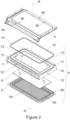
Figure 2 is an exploded view of the microwave oven ofFigure 1 , with parts removed for clarity; -
Figure 3 is a perspective view of the oven door of the microwave oven ofFigure 1 , with parts removed for clarity; -
Figure 4 is an enlarged cross-sectional view of a portion of the microwave oven ofFigure 1 according to the section plane A-A ofFigure 3 , with parts removed for clarity; and -
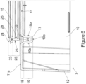
Figure 5 is an enlarged cross-sectional and partially exploded view of a portion of the oven door of the microwave oven ofFigure 1 according to the section plane B-B ofFigure 3 , with parts removed for clarity. - With reference to
Figure 1 , number 1 denotes as a whole an oven, in particular an oven with a microwave heating function, for the thermal treatment, in particular for the heating, of items such as food products. - Oven 1 may be a microwave oven or a multifunctional oven with a microwave heating function.
- The item to be thermally treated can be provided in solid and/or liquid form. The item to be thermally treated can be a food product such as meat, vegetables, beverages, soups, water and the like.
- In the following, reference will be made explicitly to a microwave oven. However, it is clear that the present invention it is not limited to the microwave oven, but it may be related also to any kind of oven, preferentially of any kind of multifunctional oven with a microwave heating function, for instance a combined microwave and steam oven.
- Oven 1 comprises a box-shaped oven body 2 extending along a reference axis R. Oven body 2 includes an
oven cavity 3, which is adapted to contain the item to be heated and is provided with afront opening 3a for the access to the inside volume ofoven cavity 3. Additionally, oven body 2 includes aperimeter front frame 4, which is carried by theoven cavity 3 and encloses at least partially thefront opening 3a of theoven cavity 3. - In particular, reference axis R may be normal to
front opening 3a. In addition, a depth ofoven cavity 3 may be defined with respect to reference axis A. - In addition, oven 1 comprises an oven door 6 (only partially shown in
Figure 1 and2 ), which is carried in an angular moveable manner by oven body 2 and is rotatable from and towards a closed position. In the closed position,oven door 6 is located into abutment against theperimeter front frame 4, so as to close thefront opening 3a of theoven cavity 3. - According to the exemplary embodiment shown in
Figure 1 , in particular,oven cavity 3 may have a substantially parallelepiped shape, and thefront opening 3a ofoven cavity 3 may have a substantially rectangular and/or quadratic shape. - Additionally,
perimeter front frame 4 may have a shape complementary to the shape of thefront opening 3a ofoven cavity 3. In particular,perimeter front frame 4 may have an annular shape and it may surround seamlessly thefront opening 3a ofoven cavity 3. - Preferentially,
perimeter front frame 4 may be coupled directly and seamlessly to the annular perimeter edge of theoven cavity 3 that bounds thefront opening 3a, so that no gap or crevice is left between theoven cavity 3 and theperimeter front frame 4. - In other words,
perimeter front frame 4 may be fixed tooven cavity 3 seamlessly along the entire annular perimeter edge that bounds thefront opening 3a. - According to the preferred non-limiting embodiment shown in
Figures 1 ,2 and4 ,front frame 4 may comprise a frontannular wall 4a, which lies on a plane substantially orthogonal to the reference axis R and, in use, extends cantilevered outwardly from the annular perimeter edge of theoven cavity 3 that bounds thefront opening 3a. - In addition,
perimeter front frame 4 may comprise an innerprotruding flange 4b, which extends cantilevered from the inner annular edge of the frontannular wall 4a, in a direction transversal to this latter. In particular, the protrudingflange 4b may extend in a direction orthogonal to the frontannular wall 4a, i.e. parallel to reference axis R. Additionally, protrudingflange 4b may surround seamlessly the frontannular wall 4a. - According to some preferred non-limiting embodiments,
oven cavity 3 andperimeter front frame 4 are made of metal material, such as aluminum or the like. - In particular,
perimeter front frame 4 may have a monolithic structure and it may be realized starting from a single flat sheet of metal of adequate thickness. - Additionally,
perimeter front frame 4 may be firmly fixed tooven cavity 3 by welding. - More in detail, protruding
flange 4b of theperimeter front frame 4 may be fixed in direct contact and seamlessly with the annular perimeter edge of theoven cavity 3 that bounds thefront opening 3a, so that no gap or crevice is left between theoven cavity 3 and theperimeter front frame 4 and the oven body 2 has a continuous and homogeneous front surface. - According to the preferred non-limiting embodiment shown in
Figures 1 ,2 and3 ,oven door 6 may have a box-shaped structure and may comprise at least: - an
inner door cover 7 facing the oven body 2; - an outer door cover (not shown in the Figures), which may have a shape complementary to the shape of the
inner door cover 7, and may be coupled to theinner door cover 7, on the opposite side with respect to the oven body 2; - an
inner glass panel 8, which is carried by theinner door cover 7 and faces the oven body 2; and - a metal
wave choke system 9, which is carried by theinner door cover 7 and is adapted to be arranged close toperimeter front frame 4 whenoven door 6 is in the closed position, so as to prevent microwaves leakage during microwave oven 1 operation. - More in detail, according to some preferred non-limiting embodiments, the outer door cover may comprise a front glass panel, which may carry a door handle and may be carried by the
inner door cover 7 by means of a pair of columnar fixing elements, in a manner known per se. - Additionally,
inner door cover 7 is adapted to be arranged skimming theperimeter front frame 4 whenoven door 6 is in the closed position, so as to define a narrow annular gap with this latter. - In particular, with reference to
Figure 4 , the annular gap defined between theinner door cover 7 and theperimeter front frame 4, whenoven door 6 is in the closed position, may have a thickness t lower than 2 millimeters and more advantageously lower than or equal to 1 millimeter. - Additionally, according to some preferred non-limiting embodiments, the
inner door cover 7 and/or the outer door cover may be shaped so as to define an inner cavity of theoven door 6.Inner glass panel 8 and metalwave choke system 9 may be arranged within this inner cavity. - Preferentially,
inner door cover 7 may have a monolithic structure and may be made of a polymeric material. In other words,inner door cover 7 may be formed as a single piece. - With reference to the example shown in
Figures 1-5 , in particular,inner door cover 7 may comprise a monolithic cup-shapedbody 10. - More in detail,
inner door cover 7 may comprise arear wall 11 that lies on a plane orthogonal to reference axis R and skims theperimeter front frame 4 whenoven door 6 is in the closed position. Additionally,inner door cover 7 may comprise alateral wall 12 that extends cantilevered from the outer perimeter edge of therear wall 11 in a transversal direction to this latter. Preferentially,lateral wall 12 may extend substantially orthogonal to therear wall 11. Additionally,lateral wall 12 may have an annular shape and may surround substantially seamlessly therear wall 11. - According to the preferred non-limiting embodiment shown in
Figures 2-5 , therear wall 11 of theinner door cover 7 may be provided with acentral opening 13 with a shape substantially complementary to the shape of theinner glass panel 8.Inner glass panel 8 may be arranged within thecentral opening 13 of theinner door cover 7, in order to allow a user to be able to visually inspect the inner of theoven cavity 3 through the outer glass panel and theinner glass panel 8 when theoven door 6 is in the closed position. - In particular, the
rear wall 11 of theinner door cover 7 may have an annular shape and may seamlessly surround theinner glass panel 8. - According to the preferred non-limiting embodiment shown in
Figures 2-5 , oven 1 is further provided with anannular gasket 15 that is carried byoven door 6 and is adapted to be arranged into abutment againstperimeter front frame 4 whenoven door 6 is in the closed position, in order to seal theoven cavity 3 and prevent thermal or steam leakages. In particular,inner door cover 7 carries theannular gasket 15. - Additionally,
annular gasket 15 may be formed as a single piece and may be made out of a polymeric material, for instance by means of an extrusion process. More in detail,annular gasket 15 may be made out of a single elastomeric material, for instance silicone or the like. Even more in detail, theannular gasket 15 may lack portions made out of non-polymeric material, such as metal. - According to the preferred non-limiting embodiment shown,
inner door cover 7 is provided with anannular groove 17, which extends on the surface of theinner door cover 7 facing theperimeter front frame 4 and is adapted to accommodate theannular gasket 15. In particular, theannular groove 17 may extend on therear wall 11 of the inner door cover. - With reference to the example shown in
Figures 2 and3 ,annular groove 17 may be arranged facing theperimeter front frame 4 when theoven door 6 is in the closed position, in order to surround seamlessly the front opening of theoven cavity 3. In other words,annular groove 17 may surround seamlessly thecentral opening 13, i.e. theinner glass panel 8. - Additionally, the
annular groove 17 may protrude inside the inner cavity of theoven door 6, towards the outer door cover, preferentially in a direction substantially orthogonal to the laying plane of therear wall 11. - According to the preferred non-limiting embodiment shown in
Figure 5 , theannular groove 17 may comprise a firstannular portion 18 and a secondannular portion 19, preferentially opposite and contiguous to the firstannular portion 18. - Preferentially, the first
annular portion 18 may define a mouthpiece of theannular groove 17, and the secondannular portion 19 may define a bottom of thegroove 17. - In particular, first
annular portion 18 may connect to therear wall 11 ofinner door cover 7, meaning that it may be contiguous with thesurface 11a of therear wall 11 facingperimeter front frame 4. - First
annular portion 18 may be configured to allow for placement ofannular gasket 15 withinannular groove 17. In other words, firstannular portion 18 defines and/or delimits an opening ofannular groove 17, in particular such that an operator or a machine may placeannular gasket 15 withinannular groove 17. - Additionally, first
annular portion 18 may have a tapered profile. In particular, firstannular portion 18 may be shaped so as to define anannular seat 20 accommodating a portion, preferentially a complementary-shaped portion, of theannular gasket 15. Such portion of theannular gasket 15 may be adjusted according to a shape of the firstannular portion 18, in particular for optimizing the placement ofannular gasket 15 withinannular groove 17. - On the other hand, second
annular portion 19 may connect to the firstannular portion 18 and may extend on the opposite side with respect to therear wall 11, preferentially inside the inner cavity of theoven door 6. - With reference to the example shown in
Figure 3 , theannular groove 17 may be further provided with a plurality ofcutouts 21 that are formed on the secondannular portion 19. In particular, thecutouts 21 may be angularly spaced apart from one another alongannular groove 17. - More in detail, the second
annular portion 19 ofannular groove 17 may comprise a plurality ofsections 19a, which are angularly spaced apart from one another. Eachsection 19a is interposed between tworespective cutouts 21, or vice-versa, eachcutout 21 is interposed between tworespective section 19a. - In other words, the
cutouts 21 are the results of forming the secondannular portion 19 not as a single piece, but by forming the secondannular portion 19 as a plurality of spaced apartsections 19a. - That is, the second
annular portion 19 is discrete, meaning it is not defined as a single piece but as a plurality ofdistinct segments 19a, spaced apart from one another and without being connected to one another. - In even other words, the
cutouts 21 are defined by providing recesses withinannular groove 17. - According to the preferred non-limiting embodiment shown in
Figures 4 and5 , secondannular portion 19 ofannular groove 17 preferentially may have substantially U-shaped profile and it may comprise two facingsidewalls 19b connected by abase wall 19c. - Substantially U-shaped indicates that the profile mainly reflects a U-shape; i.e. the profile may deviate in minor parts from the U-shape. E.g. also a shape which may rather reflect a V-shape can be considered as a U-shape.
- Preferentially,
base wall 19c may be substantially parallel torear wall 11 andsidewalls 19b may substantially orthogonal torear wall 11. - Additionally, according to the preferred non-limiting embodiment shown in
Figures 4 and5 ,annular gasket 15 may have a substantially T-shaped profile. - Substantially T-shaped indicates that the profile mainly resembles the shape of a T; i.e. the profile may deviate in minor parts from the T-shape.
- In particular,
annular gasket 15 may comprise a firstannular portion 22 and a secondannular portion 23. Firstannular portion 22 being enlarged with respect to the secondannular portion 23. Preferentially, firstannular portion 22 and secondannular portion 23 connect to each another. - Preferentially, first
annular portion 22 of theannular gasket 15 may be arranged at least partially within the firstannular portion 18 of theannular groove 17. On the other hand, secondannular portion 23 may be arranged within the secondannular portion 19 of theannular groove 17. - More in detail, at least a part of the first
annular portion 22 of theannular gasket 15 may have a shape complementary to the shape of the firstannular portion 18 ofannular groove 17. - In even more detail, at least a part of the first
annular portion 22 of theannular gasket 15 may have a shape complementary to the shape of theannular seat 20 of theannular groove 17, and may be arranged within theannular seat 20. - Additionally, according to the preferred non-limiting embodiment shown in
Figures 4 and5 , firstannular portion 22 may be sized so as to at least partially protrude cantilevered frominner door cover 7 whenannular gasket 15 is arranged withinannular groove 17, in order to abut againstperimeter front frame 4 whenoven door 6 is in the closed position. - More in detail, with reference to
Figure 4 , firstannular portion 22 may protrude cantilevered frominner door cover 7 for an extension at least equal to the thickness t of the annular gap defined between theperimeter front frame 6 and theinner door cover 7 when theoven door 6 is in the closed position. - In even more detail, as shown in the example of
Figures 4 and5 , firstannular portion 22 may be provided with protrudingannular lip 24 that is configured to be arranged into abutment againstperimeter front frame 4 whenoven door 6 is in the closed position. - Preferentially, protruding
annular lip 24 may have a C-shaped profile and may extend seamlessly along firstannular portion 22 for the entire length ofannular gasket 15. - In particular, the C-shaped profile of the protruding
annular lip 24 is configured to create an under pressure area when it is pressed againstperimeter front frame 4, to sealoven cavity 3 against thermal and/or steam leakages. - According to the preferred non-limiting embodiment shown in
Figures 4 and5 ,annular gasket 15 may be provided with anchoring means, which are configured to engage withinannular groove 17, in order to steadily retainannular gasket 15 inside theannular groove 17. In particular, the anchoring means may be configured to engage withsidewalls 19b of secondannular portion 19 of theannular groove 17. - More in detail and with reference to
Figures 4 and5 ,annular gasket 15 may be provided with a pair of laterally protrudinglips 25 that protrude from opposite sides ofannular gasket 15 and extend cantilevered from secondannular portion 23, preferentially in a direction transversal toannular gasket 15 and/or towards firstannular portion 22. The two laterally protrudinglips 25 engage with thelateral walls 19b of secondannular portion 19 of theannular groove 17. - In particular, as shown in
Figure 4 , the sections of the laterally protrudinglips 25 that are located within thecutouts 21 may locally extend in a direction transversal to theannular gasket 15 and/or towards firstannular portion 22, in order to engage with the edges ofsidewalls 19b ofannular groove 17 that boundscutouts 21, so as to hookannular gasket 15 inside this latter. - Preferentially, the two laterally protruding
lips 25 extend seamlessly for the entire length ofannular gasket 15. - With reference to the example shown in
Figure 5 , the secondannular portion 23 of theannular gasket 15 may be additionally provided with anend 26, opposite to the firstannular portion 22 and preferably enlarged with respect to the other portions of the secondannular portion 23, which is configured to be gripped by an operator or a robot, in order to allow pulling down and adjusting the position ofannular gasket 15 withinannular groove 17. - Additionally, the annular groove may 15 may be provided with an annular
hollow core 28, which extends insideannular gasket 15 and is adapted to allow theannular gasket 15 to deform elastically when pressed againstperimeter front frame 4. - Preferentially, the annular
hollow core 28 may extend seamlessly for the entire length ofannular gasket 15. - According to the preferred non-limiting embodiment shown in
Figure 2 , theinner glass panel 8 may be interposed between theinner door cover 7 and the metalwave choke system 20. In particular, the metalwave choke system 20 may be carried by the inner door cover so as to enclose theinner glass panel 8. - More in detail, the metal
wave choke system 9 may be provided with anannular portion 9a that is adapted to be arranged into abutment on the outer surface of therear wall 11 of theinner door cover 7, opposite to the oven body 2, so as to be located close to thefront frame 4 when theoven door 6 is in the closed position. - The metal
wave choke system 9 may be further provided with anannular slot 9b, which may be realized in theannular portion 9a of the metalwave choke system 9 and may have a shape complementary to the shape of theannular groove 17. Theannular slot 9b may be arranged about theannular groove 17 when the metalwave choke system 9 is placed on theinner door cover 7, so that theannular portion 9a may enclose completely theannular groove 17 and theannular gasket 15 and may be arranged into abutment against the outer surface of therear wall 11 of the inner door cover - The operation of the
oven door 6 of the microwave oven 1 is easily deduced from the above, and needs no further explanations. - Clearly, changes may be made to the microwave oven 1 without, however, departing from the scope of the present invention.
- For example, according to an alternative embodiment of the present invention, the
oven cavity 3 and theperimeter front frame 4 may be made as a single piece. Indeed, theoven cavity 3 and theperimeter front frame 4 may be made starting from a single sheet of metal of adequate thickness. - In addition, in a further alternative embodiment of the present invention, the
annular gasket 15 may not be provided with the hollow annular core 17d. -
- 1
- Oven
- 2
- Oven body
- 3
- Oven cavity
- 3a
- Front opening
- 4
- Perimeter front frame
- 4a
- Front annular wall
- 4b
- Protruding flange
- 6
- Oven door
- 7
- Inner door cover
- 8
- Inner glass panel
- 9
- Wave choke system
- 9a
- Annular portion
- 9b
- Annular slot
- 10
- Cup-shaped body
- 11
- Rear wall
- 11a
- Surface
- 12
- Lateral wall
- 13
- Central opening
- 15
- Annular gasket
- 17
- Annular groove
- 18
- First annular portion
- 19
- Second annular portion
- 19a
- Sections
- 19b
- Sidewalls
- 19c
- Base wall
- 20
- Annular seat
- 21
- Cutouts
- 22
- First annular portion
- 23
- Second annular portion
- 24
- Protruding annular lip
- 25
- Laterally protruding lips
- 26
- End
- 28
- Annular hollow core
- R
- Reference axis
- t
- Thickness
Claims (15)
- - An oven (1), preferentially having a microwave heating function, for heating an item comprising at least:- an oven cavity (3), which extends along a reference axis (R), is adapted to contain the item to be thermally treated and is provided with a front opening (3a) allowing to access the oven cavity (3);- a perimeter front frame (4), which is carried by the oven cavity (3) and surrounds the front opening (3a) of the oven cavity (3);- an oven door (6), which is movable from and towards a closed position, in which the oven door (6) closes the front opening (3a) of the oven cavity (3); and- an annular gasket (15), which is carried by the oven door (6) and is configured to abut against the perimeter front frame (4) when the oven door (6) is in the closed position, in order to seal the oven cavity (3);the oven door (6) comprising an inner door cover (7) which is configured to be arranged skimming the perimeter front frame (4) when the oven door (6) is in the closed position, and is provided with an annular groove (17) which extends on the surface of the inner door cover (7) facing the front frame (4) and accommodating the annular gasket (15).
- - The oven according to claim 1, wherein the inner door cover (7) is formed as a single piece and comprises a rear wall (11) that lies on a plane orthogonal to the reference axis (R) and skims the perimeter front frame (4) when the oven door (6) is in the closed position; the annular groove (17) extends on the rear wall (11) of the inner door cover (7) so as to surround seamlessly the front opening (3a) of the oven cavity (3) when the oven door (6) is in the closed position.
- - The oven according to claim 2, wherein the annular gasket (15) is provided with anchoring means that are adapted to engage within the annular groove (17), in order to steadily retain the annular gasket (15) inside the annular groove (17).
- - The oven according to claim 3, wherein the annular groove (17) comprises: a first annular groove portion (18), which connects to the rear wall (11) and delimits an opening of the annular groove (17) allowing the annular gasket (15) to be at least partially arranged within the annular groove (17); and a second annular groove portion (19), which connects to the first annular groove portion (18), on the opposite side with respect to the rear wall (11) .
- - The oven according to claim 4, wherein the first annular groove portion (18) is shaped so as to define a seat (20) accommodating a portion of the annular gasket (15) .
- - The oven according to claim 4 or 5, wherein the annular groove (17) is provided with a plurality of cutouts (21) that are formed in the second annular groove portion (19) and are angularly spaced apart from one another along the annular groove (17).
- - The oven according to claim 5 or 6, wherein the annular gasket (15) comprises: a first annular gasket portion (22), which is arranged at least partially within the first annular groove portion (18) and protrudes cantilevered from the inner door cover (7), in order to abut against the perimeter front frame (4) when the oven door (6) is in the closed position; and a second annular gasket portion (23), which connects to the first annular gasket portion (22) and is arranged within the second annular groove portion (23).
- - The oven door according to claim 7, wherein the second annular groove portion (19) has a substantially U-shaped profile and comprises two facing sidewalls (19b) connected by a base wall (19a).
- - The oven according to claim 8, wherein the anchoring means comprise a pair of laterally protruding lips (25), which protrude from opposite sides of the second annular gasket portion (23), in a direction transversal to annular gasket (15) and/or towards the first annular portion (22), and are configured to engage with the sidewalls (19b) of the second annular groove portion (19).
- - The oven according to claim 7, 8 or 9, wherein the first annular gasket portion (22) is provided with a protruding annular lip (24) configured to be pressed against the perimeter front frame (4) when the oven door (6) is in the closed position.
- The oven according to any of the preceding claims, wherein the annular gasket (15) is formed as a single piece and is made out of a single polymeric material.
- - The oven according to any of the preceding claims, wherein the perimeter front frame (4) is connected directly and seamlessly to the annular perimeter edge of the oven cavity (3) that bounds the front opening (3a), so that no gap or crevice is left between the perimeter edge of the oven cavity (3) that bounds the front opening (3a) and the perimeter front frame (4).
- - The oven according to any of the preceding claims, wherein the oven door (6) further comprises:- an outer door cover that has a shape complementary to the shape of the inner door cover (7) and is adapted to be coupled to the inner door cover (7), on the opposite side with respect to the oven cavity (3);- an inner glass panel (8) carried between the inner door cover (7) and the outer door cover; and- a wave choke system (9), carried between the inner door cover (7) and the outer door cover.
- - The oven according to claim 13, wherein the wave choke system (9) is provided with an annular portion (9a) that is adapted to be arranged into abutment on the surface inner door cover opposite to the oven cavity (3), so as to be placed close to the perimeter front frame (4) when the oven door (6) is in the closed position.
- - The oven according to claim 14, wherein the metal wave choke system (9) is provided with an annular slot (9b), which is realized in the annular portion (9a) of the wave choke system (9), has a shape complementary to the shape of the annular groove (17) of the inner door cover (7), and is adapted to be arranged about the annular groove (17) when the metal wave choke system (9) is placed on the inner door cover (7), so that the annular portion (9a) of the wave choke system (9) may enclose completely the annular groove (17) and the annular gasket (15).
Priority Applications (3)
| Application Number | Priority Date | Filing Date | Title |
|---|---|---|---|
| EP22200315.4A EP4351277A1 (en) | 2022-10-07 | 2022-10-07 | Oven |
| AU2023214238A AU2023214238A1 (en) | 2022-10-07 | 2023-08-08 | Oven |
| CN202311237814.2A CN117837950A (en) | 2022-10-07 | 2023-09-25 | oven |
Applications Claiming Priority (1)
| Application Number | Priority Date | Filing Date | Title |
|---|---|---|---|
| EP22200315.4A EP4351277A1 (en) | 2022-10-07 | 2022-10-07 | Oven |
Publications (1)
| Publication Number | Publication Date |
|---|---|
| EP4351277A1 true EP4351277A1 (en) | 2024-04-10 |
Family
ID=83689311
Family Applications (1)
| Application Number | Title | Priority Date | Filing Date |
|---|---|---|---|
| EP22200315.4A Pending EP4351277A1 (en) | 2022-10-07 | 2022-10-07 | Oven |
Country Status (3)
| Country | Link |
|---|---|
| EP (1) | EP4351277A1 (en) |
| CN (1) | CN117837950A (en) |
| AU (1) | AU2023214238A1 (en) |
Citations (4)
| Publication number | Priority date | Publication date | Assignee | Title |
|---|---|---|---|---|
| EP0726423A2 (en) * | 1995-02-10 | 1996-08-14 | REHAU AG + Co | Gasket for baking oven |
| US20080149629A1 (en) * | 2005-04-22 | 2008-06-26 | Premark Feg L.L.C. | Microwave Oven With a Mask For Wave Trap |
| DE102014201426A1 (en) * | 2014-01-27 | 2015-07-30 | BSH Hausgeräte GmbH | Cooking appliance |
| WO2015159161A1 (en) * | 2014-04-16 | 2015-10-22 | Gorenje Gospodinjski Aparati, D.D. | A door gasket of a household apparatus |
-
2022
- 2022-10-07 EP EP22200315.4A patent/EP4351277A1/en active Pending
-
2023
- 2023-08-08 AU AU2023214238A patent/AU2023214238A1/en active Pending
- 2023-09-25 CN CN202311237814.2A patent/CN117837950A/en active Pending
Patent Citations (4)
| Publication number | Priority date | Publication date | Assignee | Title |
|---|---|---|---|---|
| EP0726423A2 (en) * | 1995-02-10 | 1996-08-14 | REHAU AG + Co | Gasket for baking oven |
| US20080149629A1 (en) * | 2005-04-22 | 2008-06-26 | Premark Feg L.L.C. | Microwave Oven With a Mask For Wave Trap |
| DE102014201426A1 (en) * | 2014-01-27 | 2015-07-30 | BSH Hausgeräte GmbH | Cooking appliance |
| WO2015159161A1 (en) * | 2014-04-16 | 2015-10-22 | Gorenje Gospodinjski Aparati, D.D. | A door gasket of a household apparatus |
Also Published As
| Publication number | Publication date |
|---|---|
| CN117837950A (en) | 2024-04-09 |
| AU2023214238A1 (en) | 2024-05-02 |
Similar Documents
| Publication | Publication Date | Title |
|---|---|---|
| CA2780504C (en) | Household appliance having a latch retainer for an all glass inner door | |
| US9347674B2 (en) | Household appliance having a mounting system for door skin outer glass | |
| KR100652599B1 (en) | Microwave Cooking Machine | |
| AU2023214238A1 (en) | Oven | |
| KR100786079B1 (en) | Door assembly for home appliances and heating device using same | |
| KR20050031286A (en) | Microwave oven | |
| CA2782158C (en) | Household appliance having a mounting system for a middle door glass | |
| EP1923638B1 (en) | Cooking device | |
| KR960704487A (en) | Metal cooker expense insulation handle | |
| KR100782178B1 (en) | Electric oven | |
| KR200253016Y1 (en) | structure for maintain gap between outer panel and inner panel of door in gas oven range | |
| KR100778689B1 (en) | Cookware Adjustable Microwave | |
| KR100270866B1 (en) | Cabinet deformation prevention structure of microwave oven | |
| KR100640776B1 (en) | Assembly structure of the magnetron and waveguide of the food and microwave oven | |
| KR960006058Y1 (en) | Microwave oven | |
| KR19980011554U (en) | Microwave oven with outer casing equipped with assembly position | |
| KR960002688Y1 (en) | Microwave oven | |
| KR100369828B1 (en) | Microwave oven | |
| WO2026007555A1 (en) | Fixing piece for household appliance, positioning piece, and household appliance | |
| KR100239525B1 (en) | External panel assembly device of microwave oven | |
| JP2025072024A (en) | handle | |
| EP2035752B1 (en) | An oven | |
| KR0114923Y1 (en) | Door apparatus of a microwave oven | |
| JPS62213616A (en) | Heating cooker | |
| KR19980038602A (en) | microwave |
Legal Events
| Date | Code | Title | Description |
|---|---|---|---|
| PUAI | Public reference made under article 153(3) epc to a published international application that has entered the european phase |
Free format text: ORIGINAL CODE: 0009012 |
|
| STAA | Information on the status of an ep patent application or granted ep patent |
Free format text: STATUS: THE APPLICATION HAS BEEN PUBLISHED |
|
| AK | Designated contracting states |
Kind code of ref document: A1 Designated state(s): AL AT BE BG CH CY CZ DE DK EE ES FI FR GB GR HR HU IE IS IT LI LT LU LV MC ME MK MT NL NO PL PT RO RS SE SI SK SM TR |
|
| STAA | Information on the status of an ep patent application or granted ep patent |
Free format text: STATUS: REQUEST FOR EXAMINATION WAS MADE |
|
| 17P | Request for examination filed |
Effective date: 20241010 |
|
| RBV | Designated contracting states (corrected) |
Designated state(s): AL AT BE BG CH CY CZ DE DK EE ES FI FR GB GR HR HU IE IS IT LI LT LU LV MC ME MK MT NL NO PL PT RO RS SE SI SK SM TR |