EP4351061A1 - Uplink data transmission method and apparatus, terminal and medium - Google Patents
Uplink data transmission method and apparatus, terminal and medium Download PDFInfo
- Publication number
- EP4351061A1 EP4351061A1 EP22815352.4A EP22815352A EP4351061A1 EP 4351061 A1 EP4351061 A1 EP 4351061A1 EP 22815352 A EP22815352 A EP 22815352A EP 4351061 A1 EP4351061 A1 EP 4351061A1
- Authority
- EP
- European Patent Office
- Prior art keywords
- indication information
- uplink data
- waveform
- target
- dmrs
- Prior art date
- Legal status (The legal status is an assumption and is not a legal conclusion. Google has not performed a legal analysis and makes no representation as to the accuracy of the status listed.)
- Pending
Links
Images

Classifications
-
- H—ELECTRICITY
- H04—ELECTRIC COMMUNICATION TECHNIQUE
- H04W—WIRELESS COMMUNICATION NETWORKS
- H04W72/00—Local resource management
- H04W72/12—Wireless traffic scheduling
- H04W72/1263—Mapping of traffic onto schedule, e.g. scheduled allocation or multiplexing of flows
- H04W72/1268—Mapping of traffic onto schedule, e.g. scheduled allocation or multiplexing of flows of uplink data flows
-
- H—ELECTRICITY
- H04—ELECTRIC COMMUNICATION TECHNIQUE
- H04L—TRANSMISSION OF DIGITAL INFORMATION, e.g. TELEGRAPHIC COMMUNICATION
- H04L1/00—Arrangements for detecting or preventing errors in the information received
- H04L1/0001—Systems modifying transmission characteristics according to link quality, e.g. power backoff
- H04L1/0002—Systems modifying transmission characteristics according to link quality, e.g. power backoff by adapting the transmission rate
- H04L1/0003—Systems modifying transmission characteristics according to link quality, e.g. power backoff by adapting the transmission rate by switching between different modulation schemes
-
- H—ELECTRICITY
- H04—ELECTRIC COMMUNICATION TECHNIQUE
- H04L—TRANSMISSION OF DIGITAL INFORMATION, e.g. TELEGRAPHIC COMMUNICATION
- H04L1/00—Arrangements for detecting or preventing errors in the information received
- H04L1/0001—Systems modifying transmission characteristics according to link quality, e.g. power backoff
- H04L1/0009—Systems modifying transmission characteristics according to link quality, e.g. power backoff by adapting the channel coding
-
- H—ELECTRICITY
- H04—ELECTRIC COMMUNICATION TECHNIQUE
- H04L—TRANSMISSION OF DIGITAL INFORMATION, e.g. TELEGRAPHIC COMMUNICATION
- H04L1/00—Arrangements for detecting or preventing errors in the information received
- H04L1/0001—Systems modifying transmission characteristics according to link quality, e.g. power backoff
- H04L1/0023—Systems modifying transmission characteristics according to link quality, e.g. power backoff characterised by the signalling
- H04L1/0026—Transmission of channel quality indication
-
- H—ELECTRICITY
- H04—ELECTRIC COMMUNICATION TECHNIQUE
- H04L—TRANSMISSION OF DIGITAL INFORMATION, e.g. TELEGRAPHIC COMMUNICATION
- H04L27/00—Modulated-carrier systems
- H04L27/0008—Modulated-carrier systems arrangements for allowing a transmitter or receiver to use more than one type of modulation
-
- H—ELECTRICITY
- H04—ELECTRIC COMMUNICATION TECHNIQUE
- H04L—TRANSMISSION OF DIGITAL INFORMATION, e.g. TELEGRAPHIC COMMUNICATION
- H04L27/00—Modulated-carrier systems
- H04L27/0012—Modulated-carrier systems arrangements for identifying the type of modulation
-
- H—ELECTRICITY
- H04—ELECTRIC COMMUNICATION TECHNIQUE
- H04L—TRANSMISSION OF DIGITAL INFORMATION, e.g. TELEGRAPHIC COMMUNICATION
- H04L27/00—Modulated-carrier systems
- H04L27/26—Systems using multi-frequency codes
- H04L27/2601—Multicarrier modulation systems
- H04L27/2602—Signal structure
- H04L27/261—Details of reference signals
- H04L27/2613—Structure of the reference signals
- H04L27/26136—Pilot sequence conveying additional information
-
- H—ELECTRICITY
- H04—ELECTRIC COMMUNICATION TECHNIQUE
- H04L—TRANSMISSION OF DIGITAL INFORMATION, e.g. TELEGRAPHIC COMMUNICATION
- H04L27/00—Modulated-carrier systems
- H04L27/26—Systems using multi-frequency codes
- H04L27/2601—Multicarrier modulation systems
- H04L27/2626—Arrangements specific to the transmitter only
- H04L27/2627—Modulators
- H04L27/2634—Inverse fast Fourier transform [IFFT] or inverse discrete Fourier transform [IDFT] modulators in combination with other circuits for modulation
- H04L27/2636—Inverse fast Fourier transform [IFFT] or inverse discrete Fourier transform [IDFT] modulators in combination with other circuits for modulation with FFT or DFT modulators, e.g. standard single-carrier frequency-division multiple access [SC-FDMA] transmitter or DFT spread orthogonal frequency division multiplexing [DFT-SOFDM]
-
- H—ELECTRICITY
- H04—ELECTRIC COMMUNICATION TECHNIQUE
- H04L—TRANSMISSION OF DIGITAL INFORMATION, e.g. TELEGRAPHIC COMMUNICATION
- H04L5/00—Arrangements affording multiple use of the transmission path
- H04L5/0001—Arrangements for dividing the transmission path
- H04L5/0003—Two-dimensional division
- H04L5/0005—Time-frequency
- H04L5/0007—Time-frequency the frequencies being orthogonal, e.g. OFDM(A) or DMT
-
- H—ELECTRICITY
- H04—ELECTRIC COMMUNICATION TECHNIQUE
- H04L—TRANSMISSION OF DIGITAL INFORMATION, e.g. TELEGRAPHIC COMMUNICATION
- H04L5/00—Arrangements affording multiple use of the transmission path
- H04L5/0001—Arrangements for dividing the transmission path
- H04L5/0014—Three-dimensional division
- H04L5/0023—Time-frequency-space
-
- H—ELECTRICITY
- H04—ELECTRIC COMMUNICATION TECHNIQUE
- H04L—TRANSMISSION OF DIGITAL INFORMATION, e.g. TELEGRAPHIC COMMUNICATION
- H04L5/00—Arrangements affording multiple use of the transmission path
- H04L5/0001—Arrangements for dividing the transmission path
- H04L5/0028—Variable division
-
- H—ELECTRICITY
- H04—ELECTRIC COMMUNICATION TECHNIQUE
- H04L—TRANSMISSION OF DIGITAL INFORMATION, e.g. TELEGRAPHIC COMMUNICATION
- H04L5/00—Arrangements affording multiple use of the transmission path
- H04L5/003—Arrangements for allocating sub-channels of the transmission path
- H04L5/0044—Allocation of payload; Allocation of data channels, e.g. PDSCH or PUSCH
-
- H—ELECTRICITY
- H04—ELECTRIC COMMUNICATION TECHNIQUE
- H04L—TRANSMISSION OF DIGITAL INFORMATION, e.g. TELEGRAPHIC COMMUNICATION
- H04L5/00—Arrangements affording multiple use of the transmission path
- H04L5/003—Arrangements for allocating sub-channels of the transmission path
- H04L5/0048—Allocation of pilot signals, i.e. of signals known to the receiver
-
- H—ELECTRICITY
- H04—ELECTRIC COMMUNICATION TECHNIQUE
- H04L—TRANSMISSION OF DIGITAL INFORMATION, e.g. TELEGRAPHIC COMMUNICATION
- H04L5/00—Arrangements affording multiple use of the transmission path
- H04L5/003—Arrangements for allocating sub-channels of the transmission path
- H04L5/0048—Allocation of pilot signals, i.e. of signals known to the receiver
- H04L5/0051—Allocation of pilot signals, i.e. of signals known to the receiver of dedicated pilots, i.e. pilots destined for a single user or terminal
-
- H—ELECTRICITY
- H04—ELECTRIC COMMUNICATION TECHNIQUE
- H04L—TRANSMISSION OF DIGITAL INFORMATION, e.g. TELEGRAPHIC COMMUNICATION
- H04L5/00—Arrangements affording multiple use of the transmission path
- H04L5/0091—Signalling for the administration of the divided path, e.g. signalling of configuration information
-
- H—ELECTRICITY
- H04—ELECTRIC COMMUNICATION TECHNIQUE
- H04W—WIRELESS COMMUNICATION NETWORKS
- H04W72/00—Local resource management
- H04W72/20—Control channels or signalling for resource management
- H04W72/23—Control channels or signalling for resource management in the downlink direction of a wireless link, i.e. towards a terminal
- H04W72/232—Control channels or signalling for resource management in the downlink direction of a wireless link, i.e. towards a terminal the control data signalling from the physical layer, e.g. DCI signalling
-
- H—ELECTRICITY
- H04—ELECTRIC COMMUNICATION TECHNIQUE
- H04L—TRANSMISSION OF DIGITAL INFORMATION, e.g. TELEGRAPHIC COMMUNICATION
- H04L5/00—Arrangements affording multiple use of the transmission path
- H04L5/003—Arrangements for allocating sub-channels of the transmission path
- H04L5/0053—Allocation of signalling, i.e. of overhead other than pilot signals
-
- Y—GENERAL TAGGING OF NEW TECHNOLOGICAL DEVELOPMENTS; GENERAL TAGGING OF CROSS-SECTIONAL TECHNOLOGIES SPANNING OVER SEVERAL SECTIONS OF THE IPC; TECHNICAL SUBJECTS COVERED BY FORMER USPC CROSS-REFERENCE ART COLLECTIONS [XRACs] AND DIGESTS
- Y02—TECHNOLOGIES OR APPLICATIONS FOR MITIGATION OR ADAPTATION AGAINST CLIMATE CHANGE
- Y02D—CLIMATE CHANGE MITIGATION TECHNOLOGIES IN INFORMATION AND COMMUNICATION TECHNOLOGIES [ICT], I.E. INFORMATION AND COMMUNICATION TECHNOLOGIES AIMING AT THE REDUCTION OF THEIR OWN ENERGY USE
- Y02D30/00—Reducing energy consumption in communication networks
- Y02D30/70—Reducing energy consumption in communication networks in wireless communication networks
Definitions
- This application pertains to the field of communication technologies, and specifically relates to an uplink data transmission method and apparatus, a terminal, and a medium.
- Radio Resource Control Radio Resource Control
- UE may receive radio resource control (Radio Resource Control, RRC) signaling from a network-side device and transmit uplink data using cyclic prefix orthogonal frequency division multiplexing (Cyclic Prefix Orthogonal Frequency Division Multiplexing, CP-OFDM) waveform or discrete fourier transform-spread orthogonal frequency division multiplexing (Discrete Fourier Transform-Spread Orthogonal Frequency Division Multiplexing, DFT-S-OFDM) waveform based on waveform configuration information contained in the RRC signaling.
- RRC Radio Resource Control
- UE can transmit a single stream of uplink data using the CP-OFDM waveform, referred to as single-stream transmission; alternatively, the UE can transmit multiple streams of uplink data using the DFT-S-OFDM waveform, referred to as multi-stream transmission.
- Embodiments of this application provide an uplink data transmission method and apparatus, a terminal, and a medium, able to solve the problem of low amplifier efficiency of UE.
- an uplink data transmission method includes: in a case that UE is configured to transmit uplink data using a first waveform, receiving, by the UE, target downlink control information DCI from a network-side device, where the target DCI is used for scheduling the target uplink data; and in a case that indication information contained in the target DCI satisfies a first preset condition, transmitting, by the UE, the target uplink data using a second waveform; where the indication information is used to indicate a transmission parameter for the target uplink data.
- an uplink data transmission apparatus includes a receiving module and a transmission module.
- the receiving module is configured to receive target DCI from a network-side device in a case that the uplink data transmission apparatus is configured to transmit uplink data using a first waveform, where the target DCI is used for scheduling target uplink data.
- the transmission module is configured to transmit the target uplink data using the second waveform in a case that the indication information contained in the target DCI received by the receiving module satisfies a first preset condition; where the indication information is used to indicate a transmission parameter for the target uplink data.
- a terminal includes a processor, a memory, and a program or instructions stored on the memory and executable on the processor, and when the program or instructions are executed by the processor, the steps of the method in the first aspect are implemented.
- a terminal including a processor and a communication interface.
- the communication interface is used to receive target downlink control information DCI from a network-side device in a case that the terminal is configured to transmit uplink data using a first waveform, where the target DCI is used for scheduling target uplink data; and to transmit the target uplink data using a second waveform in a case that indication information contained in the target DCI satisfies a first preset condition; where the indication information is used to indicate a transmission parameter for the target uplink data.
- a readable storage medium stores a program or instructions, and when the program or instructions are executed by a processor, the steps of the method in the first aspect or the steps of the method in the third aspect are implemented.
- a chip includes a processor and a communications interface.
- the communications interface is coupled to the processor, and the processor is configured to run a program or instructions to implement the method according to the first aspect.
- a computer program/program product is provided.
- the computer program/program product is stored in a non-volatile storage medium, and the program/program product is executed by at least one processor to realize the steps of the method in the first aspect.
- the UE in a case that UE is configured to transmit uplink data using a first waveform, the UE may receive, from a network-side device, target DCI used for scheduling target uplink data, and in a case that indication information contained in the target DCI for indicating a transmission parameter for the target uplink data satisfies a first preset condition, directly transmit the target uplink data using a second waveform.
- the UE can determine whether the indication information contained in the target DCI satisfies the first preset condition, and in the case that the indication information is determined to satisfy the first preset condition, the UE transmits the target uplink data using the second waveform instead of transmitting the target uplink data using the preconfigured first waveform, the PAPR of reference signal symbols can be reduced. In this way, the amplifier efficiency of the UE can be improved.
- the waveform for the UE to transmit uplink data can be semi-statically configured by RRC signaling received from a network-side device.
- the UE transmits uplink data using DFT-S-OFDM and the uplink transmission is limited to single-stream transmission.
- the UE transmits uplink data using CP-OFDM, and the uplink transmission can be single-stream transmission or multi-stream transmission.
- the transmit precoding matrix indicator field is referred to as the TPMI field.
- This TPMI field can indicate both precoding information and data stream count information in one information field.
- the precoding information is used to indicate a precoding matrix.
- first, second, and the like in this specification and claims of this application are used to distinguish between similar objects rather than to describe a specific order or sequence. It should be understood that terms used in this way are interchangeable in appropriate circumstances so that the embodiments of this application can be implemented in other orders than the order illustrated or described herein.
- first and second are usually used to distinguish objects of a same type, and do not restrict a quantity of objects. For example, there may be one or a plurality of first objects.
- “and/or” in the specification and claims represents at least one of connected objects, and the character “/" generally indicates that the associated objects have an "or” relationship.
- technologies described in the embodiments of this application are not limited to a long term evolution (Long Term Evolution, LTE) or LTE-Advanced (LTE-Advanced, LTE-A) system, and may also be applied to other wireless communications systems, for example, code division multiple access (Code Division Multiple Access, CDMA), time division multiple access (Time Division Multiple Access, TDMA), frequency division multiple access (Frequency Division Multiple Access, FDMA), orthogonal frequency division multiple access (Orthogonal Frequency Division Multiple Access, OFDMA), single-carrier frequency-division multiple access (Single-carrier Frequency-Division Multiple Access, SC-FDMA), and other systems.
- code division multiple access Code Division Multiple Access
- TDMA time division multiple access
- FDMA frequency division multiple access
- OFDMA Orthogonal frequency division multiple access
- SC-FDMA single-carrier Frequency-Division Multiple Access
- system and “network” in the embodiments of this application are often used interchangeably, and the technology described herein may be used in the above-mentioned systems and radio technologies as well as other systems and radio technologies.
- NR New Radio
- NR terms are used in most of the following descriptions, although these technologies may also be applied to other applications than the NR system application, for example, the 6th generation (6th Generation, 6G) communication system.
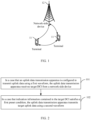
- FIG. 1 is a block diagram of a wireless communications system to which the embodiments of this application are applicable.
- the wireless communication system includes a terminal 11 and a network-side device 12.
- the terminal 11 may also be referred to as a terminal device or user equipment (User Equipment, UE), and the terminal 11 may be a terminal-side device, such as a mobile phone, a tablet computer (Tablet Personal Computer), a laptop computer (Laptop Computer) or a notebook computer, a personal digital assistant (Personal Digital Assistant, PDA), a palmtop computer, a netbook, an ultra-mobile personal computer (ultra-mobile personal computer, UMPC), a mobile Internet device (Mobile Internet Device, MID), a wearable device (Wearable Device) or vehicle user equipment (VUE), or pedestrian user equipment (PUE).
- a terminal device such as a mobile phone, a tablet computer (Tablet Personal Computer), a laptop computer (Laptop Computer) or a notebook computer, a personal digital assistant (Personal Digital Assistant, P
- the wearable device includes: a smartwatch, a wrist band, earphones, glasses, or the like. It should be noted that a specific type of the terminal 11 is not limited in the embodiments of this application.
- the network-side device 12 may be a base station or a core network.
- the base station may be referred to as a NodeB, an evolved NodeB, an access point, a base transceiver station (Base Transceiver Station, BTS), a radio base station, a radio transceiver, a basic service set (Basic Service Set, BSS), an extended service set (Extended Service Set, ESS), a NodeB, an evolved NodeB (eNB), a home NodeB, a home evolved NodeB, a WLAN access point, a Wi-Fi node, a transmission and reception Point (Transmitting Receiving Point, TRP), or another appropriate term in the art.
- the base station is not limited to a specific technical term. It should be noted that in the embodiments of this application, the base station in the NR system is merely used as an example, and a specific type of the base station is not limited.
- FIG. 2 is a flowchart of an uplink data transmission method according to an embodiment of this application. As shown in FIG. 2 , the uplink data transmission method provided in the embodiment of this application may include step 101 and step 102 as described below.
- Step 101 In a case that an uplink data transmission apparatus is configured to transmit uplink data using a first waveform, the uplink data transmission apparatus receives target DCI from a network-side device.
- the first waveform may be any one of the following: CP-OFDM and DFT-S-OFDM.
- the uplink data transmission apparatus may receive RRC signaling from the network-side device and is configured, according to transformPrecoder in the RRC signaling, to transmit uplink data using the first waveform.
- the target DCI is used for scheduling target uplink data.
- Step 102 In a case that indication information contained in the target DCI satisfies a first preset condition, the uplink data transmission apparatus transmits target uplink data using a second waveform.
- the indication information is used to indicate a transmission parameter for the target uplink data.
- the indication information may be one piece of indication information or may include a plurality pieces of sub-indication information.
- the indication information includes at least one of: TPMI field, detection reference signal resource indicator (SRS ResourceIndicator, SRI) field, frequency domain resource assignment (Frequency Domain Resource Allocation, FDRA) field, modulation and coding mode (Modulation and Coding Scheme, MCS) index value, and channel state information (Channel State Information, CSI) request field.
- SRS ResourceIndicator SRI
- Frequency Domain Resource Allocation FDRA
- MCS Modulation and Coding Scheme
- CSI Channel State Information
- the above indication information may further include at least one of the following: a physical/virtual resource block (physical/virtual Resource Block, PRB/VRB) allocation indication information field, a time domain resource assignment (Time Domain Resource Allocation, TDRA) indication information field, and a demodulation reference signal (Demodulation Reference Signal, DMRS) indication information field.
- a physical/virtual resource block physical/virtual Resource Block, PRB/VRB
- PRB/VRB physical/virtual Resource Block
- TDRA Time Domain Resource Allocation
- DMRS demodulation Reference Signal
- the above indication information satisfying the first preset condition includes at least one of the following:
- the uplink data transmission apparatus in a case that the indication information satisfies the first preset condition, it can be considered that the uplink data transmission apparatus is scheduled for single-stream transmission, and in a case that the uplink data transmission apparatus uses CP-OFDM for single-stream transmission, a PAPR of reference signal symbols is high, and therefore the uplink data transmission apparatus can use a DFT-S-OFDM waveform for single-stream transmission (that is, target uplink data transmission) to reduce the PAPR of the reference signal symbols.
- the above indication information satisfying the first preset condition includes at least one of the following:
- the uplink data transmission apparatus in a case that the indication information satisfies the first preset condition, it can be considered that the uplink data transmission apparatus is scheduled for multistream transmission, and in a case that the uplink data transmission apparatus uses DFT-S-OFDM for multi stream transmission, a PAPR of reference signal symbols is high, and therefore, the uplink data transmission apparatus can use a CP-OFDM waveform for multistream transmission (that is, target uplink data transmission) to reduce the PAPR of the reference signal symbols.
- a CP-OFDM waveform for multistream transmission that is, target uplink data transmission
- the uplink data transmission apparatus in a case that the uplink data transmission apparatus is configured to transmit the uplink data using CP-OFDM, the uplink data transmission apparatus is scheduled for single-stream transmission, and the first preset condition is satisfied, the uplink data transmission apparatus may transmit the target uplink data using DFT-S-OFDM.
- the uplink data transmission apparatus is configured to transmit the uplink data using CP-OFDM
- the uplink data transmission apparatus is scheduled for single-stream transmission, and the first preset condition is not satisfied, the uplink data transmission apparatus still transmits the target uplink data using CP-OFDM.
- the uplink data transmission apparatus may transmit the target uplink data using CP-OFDM.
- the uplink data transmission apparatus may receive target DCI from a network-side device for scheduling the target uplink data, and in a case that the indication information contained in the target DCI satisfies the first preset condition, directly transmit the target uplink data using the second waveform, where the indication information is used for indicating a transmission parameter for the target uplink data.
- the uplink data transmission apparatus may determine whether the indication information contained in the target DCI satisfies the first preset condition, and in a case that the indication information is determined to satisfy the first preset condition, the uplink data transmission apparatus transmits the target uplink data using the second waveform instead of transmitting the target uplink data using the preconfigured first waveform. Therefore, the PAPR of reference signal symbols can be reduced. In this way, the amplifier efficiency of the uplink data transmission apparatus can be improved.
- some sub-indication information in the target DCI may be invalid for the second waveform, such that the uplink data transmission apparatus may transmit the target uplink data using the second waveform based on sub-indication information other than the some sub-indication information, that is, ignoring the some sub-indication information.
- the some sub-indication information is Q pieces of sub-indication information.
- the indication information contains N pieces of sub-indication information, and N is a positive integer.
- the step 102 can be specifically realized by the following step 102a.
- Step 102a In a case that Q pieces of N pieces of sub-indication information satisfy a second preset condition, the uplink data transmission apparatus transmits target uplink data using a second waveform according to other sub-indication information.
- the other sub-indication information is sub-indication information in the N pieces of sub-indication information other than the Q pieces of sub-indication information, and Q is a positive integer.
- the uplink data transmission apparatus transmits the target uplink data using the second waveform according to the other sub-indication information, that is, the uplink data transmission apparatus ignores the Q pieces of sub-indication information that satisfy the second preset condition, of the N pieces of sub-indication information.
- the above second preset condition may specifically be that the sub-indication information is invalid for the second waveform.
- the uplink data transmission apparatus may ignore the PTRS-DMRS association.
- a phasetracking reference signal Phase Tracking Reference Signal, PTRS
- PTRS-DMRS association is 2 bits, and the PTRS-DMRS association is invalid for the second waveform (for example, DFT-S-OFDM)
- the uplink data transmission apparatus may ignore the PTRS-DMRS association.
- the uplink data transmission apparatus may transmit the target uplink data using the second waveform according to the transmission parameters indicated by other sub-indication information.
- the uplink data transmission apparatus can transmit the target uplink data using the second waveform according to the other sub-indication information that is valid for the second waveform of the N pieces of sub-indication information contained in the target DCI, without transmitting the target uplink data according to the Q pieces of sub-indication information that are invalid for the second waveform. Therefore, the reliability of the uplink data transmission apparatus in transmitting the uplink data can be improved.
- the uplink data transmission apparatus may also keep the size of specified sub-indication information of the plurality of pieces of sub-indication information unchanged, and interpret the specified sub-indication information in a new way.
- the specified sub-indication information is a DMRS indication information field.
- the indication information includes a first demodulation reference signal DMRS indication information field, where the first DMRS indication information field is used to indicate: a transmission port of a DMRS for use by the target uplink data, in a case of being configured to transmit the target uplink data using the first waveform.
- the uplink data transmission method may further include the following step 301, and the step 102 may be specifically realized by the step 102b.
- Step 301 In a case that indication information contained in the target DCI satisfies a first preset condition, the uplink data transmission apparatus determines a target transmission port based on a first DMRS indication information field.
- the uplink data transmission apparatus may, based on a preconfigured first DMRS indication table for the first waveform and a preconfigured second DMRS indication table for the second waveform, determine the target transmission port based on a first DMRS indication information field and the first DMRS indication table (or second DMRS indication table).
- the first DMRS indication table includes at least one state
- the second DMRS indication table includes at least one state
- the number of states in the first DMRS indication table is different from the number of states in the second DMRS indication table.
- Table 1 is a DMRS indication table corresponding to DFT-S-OFDM.
- Table 1 Value Index value
- this DMRS indication table includes 4 states (that is, the number of states is 4) indicated with a total of 2 bits.
- Table 2 is a DMRS indication table corresponding to CP-OFDM.
- Table 2 Value Index value
- this DMRS indication table includes 6 states (that is, the number of states is 6) indicated with a total of 3 bits.
- the first DMRS indication information field corresponds to X bits
- X is determined based on a waveform with a larger number of states between the first waveform and the second waveform, and X is a positive integer.
- X is the number of bits of a waveform with a larger number of states between the first waveform and the second waveform.
- the number of states of the first waveform is 6, the first waveform occupies 3 bits, the number of states of the second waveform is 4, and the second waveform occupies 2 bits.
- X is the number of bits of a waveform with a larger number of states (that is, the first waveform) between the first waveform and the second waveform, that is, 3 bits.
- the target transmission port is a transmission port indicated by the target bit.
- the target bit is the first Y bits or the last Z bits of X bits, and Y and Z are positive integers.
- the second waveform is DFT-S-OFDM
- the first waveform is CP-OFDM
- the number of states corresponding to DFT-S-OFDM is less than the number of states corresponding to CP-OFDM.
- the target transmission port is a DMRS port indicated by the first Y (for example, 2) bits or a DMRS port indicated by the last Z (for example, 2) bits.
- the length of the DMRS information field and the target transmission port are a transmission port determined based on a state corresponding to the second waveform.
- the second waveform is CP-OFDM and the first waveform is DFT-S-OFDM, and with reference to Tables 1 and 2, the number of states corresponding to CP-OFDM is greater than the number of states corresponding to DFT-S-OFDM.
- the length of the DMRS information field and the target transmission port are the transmission port determined according to the states corresponding to CP-OFDM (that is, six states in Table 2).
- the uplink data transmission apparatus can interpret the first DMRS indication information in a new way based on the number of states corresponding to the second waveform and the number of states corresponding to the first waveform, so as to determine the target transmission port. Therefore, the reliability of the uplink data transmission apparatus in transmitting the uplink data can be improved.
- the step 301 may be specifically implemented by the following steps 301a and 301b.
- Step 301a In a case that the indication information contained in the target DCI satisfies the first preset condition, the uplink data transmission apparatus determines an index value of a second DMRS indication information field based on the index value of the first DMRS indication information field and M first mappings.
- each of the M first mappings is a mapping between index values of different DMRS indication information fields corresponding to different waveforms, and M is a positive integer;
- the M first mappings may be mappings prestored in the uplink data transmission apparatus.
- the second DMRS indication information field is used to indicate: a transmission port of a DMRS for use by the target uplink data, in a case of being configured to transmit the target uplink data using the second waveform.
- the uplink data transmission apparatus may determine a matching first index value from M first index values of the first waveform based on the index value of the first DMRS indication information field, and then determine a mapped second index value from M second index values of the second waveform based on the first index value, and determine the second index value as the index value of the second DMRS indication information field.
- Step 301b The uplink data transmission apparatus determines the target transmission port based on the index value of the second DMRS indication information field.
- the uplink data transmission apparatus may determine the target transmission port based on the index value of the second DMRS indication information field and the first DMRS indication table (or the second DMRS indication table).
- the uplink data transmission apparatus may determine a new index value based on the index value of the first DMRS indication information field according to the M first mappings to determine the target transmission port based on the new index value. Therefore, the reliability of the uplink data transmission apparatus in transmitting the uplink data can be improved.
- Step 102b The uplink data transmission apparatus transmits a DMRS using a second waveform based on the target transmission port.
- the DMRS indication information field in the target DCI is used as an example to illustrate how the uplink data transmission apparatus interprets the sub-indication information in a new way and transmits the DMRS using the second waveform.
- the same steps as in the foregoing embodiment can be applied, and other transmission parameters indicated by the other sub-indication information can be transmitted using the second waveform to transmit the target uplink data.
- the uplink data transmission apparatus can interpret the first DMRS indication information in a new way to determine the target transmission port, such that the uplink data transmission apparatus can transmit the DMRS using the second waveform based on the target transmission port. Therefore, the reliability of the uplink data transmission apparatus in transmitting the uplink data can be improved.
- the uplink data transmission method provided in the embodiment of this application may be executed by the uplink data transmission apparatus or a control module for executing the uplink data transmission method in the uplink data transmission apparatus.
- the uplink data transmission apparatus executing the uplink data transmission method is used as an example in the embodiments of this application to describe the uplink data transmission apparatus provided in the embodiments of this application.
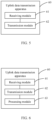
- FIG. 5 is a possible schematic structural diagram of a transmission apparatus involved in the embodiments of this application.
- the uplink data transmission apparatus 60 may include a receiving module 61 and a transmission module 62.
- the receiving module 61 is configured to receive target DCI from a network-side device in a case that the uplink data transmission apparatus 60 is configured to transmit uplink data using a first waveform, where the target DCI is used for scheduling target uplink data.
- the transmission module 62 is configured to transmit the target uplink data using a second waveform in a case that indication information contained in the target DCI received by the receiving module 61 satisfies a first preset condition. The indication information is used to indicate a transmission parameter for the target uplink data.
- the indication information includes at least one of a TPMI field, a SRI field, a FDRA field, a MCS index value, and a CSI request field.
- the above indication information satisfying the first preset condition includes at least one of the following: a rank corresponding to the TPMI field is less than or equal to a first threshold; a rank corresponding to the SRI field is less than or equal to a second threshold; PRBs indicated by the FDRA field are contiguous; the MCS index value is less than a third threshold; the indication information does not contain the CSI request field; and the indication information includes the CSI request field, and the CSI request field is not used to trigger the uplink data transmission apparatus 60 to send a CSI report.
- the indication information includes a first DMRS indication information field, where the first DMRS indication information field is used to indicate: a transmission port of a DMRS for use by the target uplink data, in a case of being configured to transmit the target uplink data using the first waveform.
- the uplink data transmission apparatus 60 provided in this embodiment of this application may further include a processing module 63.
- the processing module 63 is configured to determine a target transmission port based on the first DMRS indication information field.
- the transmission module 62 is specifically configured to transmit the DMRS using the second waveform based on the target transmission port determined by the processing module 63.
- the first DMRS indication information field corresponds to X bits, X is determined based on a waveform with a larger number of states between the first waveform and the second waveform, and X is a positive integer.
- the target transmission port is a transmission port indicated by the target bits; in a case that the number of states corresponding to the second waveform is greater than the number of states corresponding to the first waveform, the target transmission port is a transmission port determined based on the state corresponding to the second waveform.
- the target bit is the first Y bits or the last Z bits of X bits, and Y and Z are positive integers.
- the processing module 63 is specifically configured to determine an index value of a second DMRS indication information field based on an index value of the first DMRS indication information field and M first mappings, M being a positive integer; and determine the target transmission port based on the index value of the second DMRS indication information field.
- Each of the first mappings is a mapping between index values of different DMRS indication information fields corresponding to different waveforms; and the second DMRS indication information field is used to indicate: a transmission port of a DMRS for use by the target uplink data, in a case of being configured to transmit the target uplink data using the second waveform.
- the indication information contains N pieces of sub-indication information, N being a positive integer.
- the transmission module 62 is specifically configured to transmit the target uplink data using the second waveform based on other sub-indication information in a case that Q pieces of the N pieces of sub-indication information satisfy a second preset condition.
- the other sub-indication information is sub-indication information in the N pieces of sub-indication information other than the Q pieces of sub-indication information, Q being a positive integer.
- the uplink data transmission apparatus in a case that the uplink data transmission apparatus is configured to transmit the uplink data using the first waveform, the uplink data transmission apparatus may determine whether the indication information contained in the target DCI satisfies the first preset condition, and in a case that the indication information is determined to satisfy the first preset condition, the uplink data transmission apparatus transmits the target uplink data using the second waveform instead of transmitting the target uplink data using the preconfigured first waveform. Therefore, the PAPR of reference signal symbols can be reduced. In this way, the amplifier efficiency of the uplink data transmission apparatus can be improved.
- the uplink data transmission apparatus in the embodiment of this application may be an apparatus or electronic device with an operating system or may be a component, integrated circuit, or chip in a terminal.
- the apparatus or electronic device may be a mobile terminal or a non-mobile terminal.
- the mobile terminal may include but is not limited to the types of the terminal 11 listed above, and the non-mobile terminal may be a server, a network attached storage (Network Attached Storage, NAS), a personal computer (Personal Computer, PC), a television (Television, TV), a teller machine, a self-service machine, or the like, which is not specifically limited in this embodiment of this application.
- Network Attached Storage NAS
- PC Personal Computer
- TV Television
- teller machine teller machine
- self-service machine or the like, which is not specifically limited in this embodiment of this application.
- the uplink data transmission apparatus provided in the embodiments of this application can implement the processes that are implemented in the method embodiments of FIG. 1 and FIG. 4 , with the same technical effects achieved. To avoid repetition, details are not described herein again.
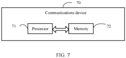
- an embodiment of this application further provides a communication device 70, including a processor 71, a memory 72, and a program or instructions stored in the memory 72 and executable on the processor 71.
- a communication device 70 including a processor 71, a memory 72, and a program or instructions stored in the memory 72 and executable on the processor 71.
- the communication device 70 is a terminal
- the program or instructions are executed by the processor 71, the processes of the foregoing embodiments of the uplink data transmission method are implemented, with the same technical effects achieved. To avoid repetition, details are not described herein again.
- An embodiment of this application further provides a terminal including a processor and a communication interface.
- the communication interface is used to receive target downlink control information DCI from a network-side device in a case that the terminal is configured to transmit uplink data using a first waveform, where the target DCI is used for scheduling target uplink data; and to transmit the target uplink data using a second waveform in a case that indication information contained in the target DCI satisfies a first preset condition; where the indication information is used to indicate a transmission parameter for the target uplink data.
- This terminal embodiment is corresponding to the above terminal-side method embodiment, and each implementation process and implementation manner of the above method embodiment can be applied in this terminal embodiment, with the same technical effects achieved.
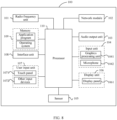
- FIG. 8 is a schematic diagram of a hardware structure of a terminal for implementing the embodiments of this application.
- the terminal 100 includes but is not limited to at least some components such as a radio frequency unit 101, a network module 102, an audio output unit 103, an input unit 104, a sensor 105, a display unit 106, a user input unit 107, an interface unit 108, a memory 109, and a processor 110.
- the terminal 100 may further include a power supply (such as a battery) for supplying power to the components.
- the power supply may be logically connected to the processor 110 through a power management system. In this way, functions such as charge management, discharge management, and power consumption management are implemented by using the power management system.
- the structure of the terminal shown in FIG. 8 does not constitute any limitation on the terminal.
- the terminal may include more or fewer components than shown in the figure, or a combination of some components, or the components disposed differently. Details are not described herein again.
- the input unit 104 may include a graphics processing unit (Graphics Processing Unit, GPU) 1041 and a microphone 1042.
- the graphics processing unit 1041 processes image data of a still picture or video obtained by an image capture apparatus (such as a camera) in a video capture mode or an image capture mode.
- the display unit 106 may include a display panel 1061, and the display panel 1061 may be configured in a form of a liquid crystal display, an organic light-emitting diode, and the like.
- the user input unit 107 includes a touch panel 1071 and other input devices 1072.
- the touch panel 1071 is also referred to as a touchscreen.
- the touch panel 1071 may include two parts: a touch detection apparatus and a touch controller.
- the other input devices 1072 may include but be not limited to a physical keyboard, a function key (such as a volume control key or an on/off key), a trackball, a mouse, and a joystick. Details are not described herein.
- the radio frequency unit 101 sends downlink data received from a network-side device to the processor 110 for processing, and in addition, sends uplink data to the network-side device.
- the radio frequency unit 101 includes but is not limited to an antenna, at least one amplifier, a transceiver, a coupler, a low noise amplifier, a duplexer, and the like.
- the memory 109 may be configured to store software programs or instructions and various data.
- the memory 109 may mainly include a program or instruction storage region and a data storage region.
- the program or instruction storage region may store an operating system, an application program or instructions required by at least one function (for example, an audio play function or an image play function), and the like.
- the memory 109 may include a high-speed random access memory, and may further include a non-volatile memory, where the non-volatile memory may be a read-only memory (Read-Only Memory, ROM), a programmable read-only memory (Programmable ROM, PROM), an erasable programmable read-only memory (Erasable PROM, EPROM), an electrically erasable programmable read-only memory (Electrically EPROM, EEPROM), or a flash memory, for example, at least one disk storage device, a flash memory device, or another non-volatile solid-state storage device.
- ROM Read-Only Memory
- PROM programmable read-only memory
- Erasable PROM Erasable PROM
- EPROM electrically erasable programmable read-only memory
- EEPROM electrically erasable programmable read-only memory
- flash memory for example, at least one disk storage device, a flash memory device, or another non-volatile solid-
- the processor 110 may include one or more processing units.
- the processor 110 may integrate an application processor and a modem processor.
- the application processor mainly processes the operating system, a user interface, an application program, or instructions, and the like.
- the modem processor mainly processes wireless communication.
- the modem processor is a baseband processor. It can be understood that the modem processor may alternatively be not integrated in the processor 110.
- the radio frequency unit 101 is configured to receive target DCI from a network-side device in a case that the terminal is configured to transmit uplink data using a first waveform, where the target DCI is used for scheduling target uplink data; and to transmit the target uplink data using a second waveform in a case that indication information contained in the target DCI satisfies a first preset condition.
- the indication information is used to indicate a transmission parameter for the target uplink data.
- the terminal in a case that the terminal is configured to transmit the uplink data using the first waveform, the terminal may determine whether the indication information contained in the target DCI satisfies the first preset condition, and in a case that the indication information is determined to satisfy the first preset condition, the terminal transmits the target uplink data using the second waveform instead of transmitting the target uplink data using the preconfigured first waveform. Therefore, the PAPR of reference signal symbols can be reduced. In this way, the amplifier efficiency of the terminal can be improved.
- the indication information contains a first demodulation reference signal DMRS indication information field, where the first DMRS indication information field is used to indicate: a transmission port of a DMRS for use by the target uplink data, in a case of being configured to transmit the target uplink data using the first waveform.
- the processor 110 is configured to determine a target transmission port based on the first DMRS indication information field.
- the radio frequency unit 101 is specifically configured to transmit the DMRS using the second waveform based on the target transmission port.
- the terminal can interpret the first DMRS indication information in a new way to determine the target transmission port, such that the terminal can transmit the DMRS using the second waveform based on the target transmission port. Therefore, the reliability of the terminal in transmitting the uplink data can be improved.
- the processor 110 is specifically configured to determine an index value of a second DMRS indication information field based on an index value of the first DMRS indication information field and M first mappings, M being a positive integer; and determine the target transmission port based on the index value of the second DMRS indication information field.
- Each of the first mappings is a mapping between index values of different DMRS indication information fields corresponding to different waveforms; and the second DMRS indication information field is used to indicate: a transmission port of a DMRS for use by the target uplink data, in a case of being configured to transmit the target uplink data using the second waveform.
- the terminal can determine a new index value based on the index value of the first DMRS indication information field according to the M first mappings to determine the target transmission port based on the new index value. Therefore, the reliability of the terminal in transmitting the uplink data can be improved.
- the indication information contains N pieces of sub-indication information, and N is a positive integer.
- the radio frequency unit 101 is specifically configured to transmit the target uplink data using the second waveform based on other sub-indication information in a case that Q pieces of the N pieces of sub-indication information satisfy a second preset condition.
- the other sub-indication information is sub-indication information in the N pieces of sub-indication information other than the Q pieces of sub-indication information, Q being a positive integer.
- the terminal can transmit the target uplink data using the second waveform according to the other sub-indication information that is valid for the second waveform of the N pieces of sub-indication information contained in the target DCI, without transmitting the target uplink data according to the Q pieces of sub-indication information that are invalid for the second waveform. Therefore, the reliability of the terminal in transmitting the uplink data can be improved.
- An embodiment of this application further provides a readable storage medium, where the readable storage medium stores a program or instructions, and when the program or instructions are executed by a processor, the processes of the foregoing embodiments of the uplink data transmission method are implemented, with the same technical effects achieved. To avoid repetition, details are not described herein again.
- the processor is a processor in the terminal described in the foregoing embodiment.
- the readable storage medium includes a computer-readable storage medium, such as a computer read-only memory (Read-Only Memory, ROM), a random access memory (Random Access Memory, RAM), a magnetic disk, or an optical disc.
- An embodiment of this application further provides a chip, where the chip includes a processor and a communications interface.
- the communications interface is coupled to the processor, and the processor is configured to run a program or instructions to implement the processes of the foregoing embodiments of the uplink data transmission method, with the same technical effects achieved. To avoid repetition, details are not described herein again.
- the chip mentioned in the embodiments of this application may also be referred to as a system-level chip, a system chip, a chip system, a system-on-chip, or the like.
- the software product is stored in a storage medium (such as a ROM/RAM, a magnetic disk, or an optical disc), and includes several instructions for instructing a terminal (which may be a mobile phone, a computer, a server, an air conditioner, a network device, or the like) to perform the methods described in the embodiments of this disclosure.
- a storage medium such as a ROM/RAM, a magnetic disk, or an optical disc
- a terminal which may be a mobile phone, a computer, a server, an air conditioner, a network device, or the like
Landscapes
- Engineering & Computer Science (AREA)
- Signal Processing (AREA)
- Computer Networks & Wireless Communication (AREA)
- Quality & Reliability (AREA)
- Physics & Mathematics (AREA)
- Discrete Mathematics (AREA)
- General Physics & Mathematics (AREA)
- Mathematical Physics (AREA)
- Mobile Radio Communication Systems (AREA)
Abstract
Description
- This application claims priority to
Chinese Patent Application No. 202110615438.0, filed with the China National Intellectual Property Administration on June 2, 2021 - This application pertains to the field of communication technologies, and specifically relates to an uplink data transmission method and apparatus, a terminal, and a medium.
- Currently, in a new radio (New Radio, NR) system, user equipment (user equipment, UE) may receive radio resource control (Radio Resource Control, RRC) signaling from a network-side device and transmit uplink data using cyclic prefix orthogonal frequency division multiplexing (Cyclic Prefix Orthogonal Frequency Division Multiplexing, CP-OFDM) waveform or discrete fourier transform-spread orthogonal frequency division multiplexing (Discrete Fourier Transform-Spread Orthogonal Frequency Division Multiplexing, DFT-S-OFDM) waveform based on waveform configuration information contained in the RRC signaling.
- Typically, UE can transmit a single stream of uplink data using the CP-OFDM waveform, referred to as single-stream transmission; alternatively, the UE can transmit multiple streams of uplink data using the DFT-S-OFDM waveform, referred to as multi-stream transmission.
- However, when the UE uses the CP-OFDM waveform for single-stream transmission, a high peak to average power ratio (Peak to Average Power Ratio, PAPR) of reference signal symbols may occur, leading to lower power amplifier efficiency.
- Embodiments of this application provide an uplink data transmission method and apparatus, a terminal, and a medium, able to solve the problem of low amplifier efficiency of UE.
- According to a first aspect, an uplink data transmission method is provided. The method includes: in a case that UE is configured to transmit uplink data using a first waveform, receiving, by the UE, target downlink control information DCI from a network-side device, where the target DCI is used for scheduling the target uplink data; and in a case that indication information contained in the target DCI satisfies a first preset condition, transmitting, by the UE, the target uplink data using a second waveform; where the indication information is used to indicate a transmission parameter for the target uplink data.
- According to a second aspect, an uplink data transmission apparatus is provided. The uplink data transmission apparatus includes a receiving module and a transmission module. The receiving module is configured to receive target DCI from a network-side device in a case that the uplink data transmission apparatus is configured to transmit uplink data using a first waveform, where the target DCI is used for scheduling target uplink data. The transmission module is configured to transmit the target uplink data using the second waveform in a case that the indication information contained in the target DCI received by the receiving module satisfies a first preset condition; where the indication information is used to indicate a transmission parameter for the target uplink data.
- According to a third aspect, a terminal is provided. The terminal includes a processor, a memory, and a program or instructions stored on the memory and executable on the processor, and when the program or instructions are executed by the processor, the steps of the method in the first aspect are implemented.
- According to a fourth aspect, a terminal is provided, including a processor and a communication interface. The communication interface is used to receive target downlink control information DCI from a network-side device in a case that the terminal is configured to transmit uplink data using a first waveform, where the target DCI is used for scheduling target uplink data; and to transmit the target uplink data using a second waveform in a case that indication information contained in the target DCI satisfies a first preset condition; where the indication information is used to indicate a transmission parameter for the target uplink data.
- According to a fifth aspect, a readable storage medium is provided. The readable storage medium stores a program or instructions, and when the program or instructions are executed by a processor, the steps of the method in the first aspect or the steps of the method in the third aspect are implemented.
- According to a sixth aspect, a chip is provided. The chip includes a processor and a communications interface. The communications interface is coupled to the processor, and the processor is configured to run a program or instructions to implement the method according to the first aspect.
- According to a seventh aspect, a computer program/program product is provided. The computer program/program product is stored in a non-volatile storage medium, and the program/program product is executed by at least one processor to realize the steps of the method in the first aspect.
- In the embodiments of this application, in a case that UE is configured to transmit uplink data using a first waveform, the UE may receive, from a network-side device, target DCI used for scheduling target uplink data, and in a case that indication information contained in the target DCI for indicating a transmission parameter for the target uplink data satisfies a first preset condition, directly transmit the target uplink data using a second waveform. As in the case that the UE is configured to transmit uplink data using the first waveform, the UE can determine whether the indication information contained in the target DCI satisfies the first preset condition, and in the case that the indication information is determined to satisfy the first preset condition, the UE transmits the target uplink data using the second waveform instead of transmitting the target uplink data using the preconfigured first waveform, the PAPR of reference signal symbols can be reduced. In this way, the amplifier efficiency of the UE can be improved.
-
-
FIG. 1 is a block diagram of a wireless communications system according to an embodiment of this application; -
FIG. 2 is a first schematic diagram of an uplink data transmission method according to an embodiment of this application; -
FIG. 3 is a second schematic diagram of an uplink data transmission method according to an embodiment of this application; -
FIG. 4 is a third schematic diagram of an uplink data transmission method according to an embodiment of this application; -
FIG. 5 is a first schematic structural diagram of an uplink data transmission apparatus according to an embodiment of this application; -
FIG. 6 is a second schematic structural diagram of an uplink data transmission apparatus according to an embodiment of this application; -
FIG. 7 is a schematic structural diagram of a communication device according to an embodiment of this application; and -
FIG. 8 is a schematic diagram of a hardware structure of a terminal according to an embodiment of this application. - The following clearly describes the technical solutions in the embodiments of this application with reference to the accompanying drawings in the embodiments of this application. Apparently, the described embodiments are only some rather than all of the embodiments of this application. All other embodiments obtained by persons of ordinary skill in the art based on the embodiments of this application shall fall within the protection scope of this application.
- The following describes in detail the terms used in the embodiments of this application.
- The waveform for the UE to transmit uplink data can be semi-statically configured by RRC signaling received from a network-side device.
- In a case that transformPrecoder in the RRC signaling is configured as enabled (enabled), the UE transmits uplink data using DFT-S-OFDM and the uplink transmission is limited to single-stream transmission.
- In a case that transformPrecoder in the RRC signaling is configured as disabled (disabled), the UE transmits uplink data using CP-OFDM, and the uplink transmission can be single-stream transmission or multi-stream transmission.
- In the embodiments of this application, the transmit precoding matrix indicator field is referred to as the TPMI field.
- This TPMI field can indicate both precoding information and data stream count information in one information field. The precoding information is used to indicate a precoding matrix.
- The terms "first", "second", and the like in this specification and claims of this application are used to distinguish between similar objects rather than to describe a specific order or sequence. It should be understood that terms used in this way are interchangeable in appropriate circumstances so that the embodiments of this application can be implemented in other orders than the order illustrated or described herein. In addition, "first" and "second" are usually used to distinguish objects of a same type, and do not restrict a quantity of objects. For example, there may be one or a plurality of first objects. In addition, "and/or" in the specification and claims represents at least one of connected objects, and the character "/" generally indicates that the associated objects have an "or" relationship.
- It should be noted that technologies described in the embodiments of this application are not limited to a long term evolution (Long Term Evolution, LTE) or LTE-Advanced (LTE-Advanced, LTE-A) system, and may also be applied to other wireless communications systems, for example, code division multiple access (Code Division Multiple Access, CDMA), time division multiple access (Time Division Multiple Access, TDMA), frequency division multiple access (Frequency Division Multiple Access, FDMA), orthogonal frequency division multiple access (Orthogonal Frequency Division Multiple Access, OFDMA), single-carrier frequency-division multiple access (Single-carrier Frequency-Division Multiple Access, SC-FDMA), and other systems. The terms "system" and "network" in the embodiments of this application are often used interchangeably, and the technology described herein may be used in the above-mentioned systems and radio technologies as well as other systems and radio technologies. In the following descriptions, a new radio (New Radio, NR) system is described for an illustration purpose, and NR terms are used in most of the following descriptions, although these technologies may also be applied to other applications than the NR system application, for example, the 6th generation (6th Generation, 6G) communication system.
-
FIG. 1 is a block diagram of a wireless communications system to which the embodiments of this application are applicable. The wireless communication system includes aterminal 11 and a network-side device 12. The terminal 11 may also be referred to as a terminal device or user equipment (User Equipment, UE), and the terminal 11 may be a terminal-side device, such as a mobile phone, a tablet computer (Tablet Personal Computer), a laptop computer (Laptop Computer) or a notebook computer, a personal digital assistant (Personal Digital Assistant, PDA), a palmtop computer, a netbook, an ultra-mobile personal computer (ultra-mobile personal computer, UMPC), a mobile Internet device (Mobile Internet Device, MID), a wearable device (Wearable Device) or vehicle user equipment (VUE), or pedestrian user equipment (PUE). The wearable device includes: a smartwatch, a wrist band, earphones, glasses, or the like. It should be noted that a specific type of the terminal 11 is not limited in the embodiments of this application. The network-side device 12 may be a base station or a core network. The base station may be referred to as a NodeB, an evolved NodeB, an access point, a base transceiver station (Base Transceiver Station, BTS), a radio base station, a radio transceiver, a basic service set (Basic Service Set, BSS), an extended service set (Extended Service Set, ESS), a NodeB, an evolved NodeB (eNB), a home NodeB, a home evolved NodeB, a WLAN access point, a Wi-Fi node, a transmission and reception Point (Transmitting Receiving Point, TRP), or another appropriate term in the art. Provided that a same technical effect is achieved, the base station is not limited to a specific technical term. It should be noted that in the embodiments of this application, the base station in the NR system is merely used as an example, and a specific type of the base station is not limited. - The following describes in detail an uplink data transmission method provided in the embodiments of this application through specific embodiments and application scenarios thereof with reference to the accompanying drawings.
-
FIG. 2 is a flowchart of an uplink data transmission method according to an embodiment of this application. As shown inFIG. 2 , the uplink data transmission method provided in the embodiment of this application may includestep 101 and step 102 as described below. -
Step 101. In a case that an uplink data transmission apparatus is configured to transmit uplink data using a first waveform, the uplink data transmission apparatus receives target DCI from a network-side device. - Optionally, in the embodiment of this application, the first waveform may be any one of the following: CP-OFDM and DFT-S-OFDM.
- Optionally, in the embodiment of this application, the uplink data transmission apparatus may receive RRC signaling from the network-side device and is configured, according to transformPrecoder in the RRC signaling, to transmit uplink data using the first waveform.
- In the embodiment of this application, the target DCI is used for scheduling target uplink data.
-
Step 102. In a case that indication information contained in the target DCI satisfies a first preset condition, the uplink data transmission apparatus transmits target uplink data using a second waveform. - In the embodiment of this application, the indication information is used to indicate a transmission parameter for the target uplink data.
- Optionally, in an embodiment of this application, the indication information may be one piece of indication information or may include a plurality pieces of sub-indication information.
- Optionally, in an embodiment of this application, the indication information includes at least one of: TPMI field, detection reference signal resource indicator (SRS ResourceIndicator, SRI) field, frequency domain resource assignment (Frequency Domain Resource Allocation, FDRA) field, modulation and coding mode (Modulation and Coding Scheme, MCS) index value, and channel state information (Channel State Information, CSI) request field.
- Further optionally, in the embodiment of this application, the above indication information may further include at least one of the following: a physical/virtual resource block (physical/virtual Resource Block, PRB/VRB) allocation indication information field, a time domain resource assignment (Time Domain Resource Allocation, TDRA) indication information field, and a demodulation reference signal (Demodulation Reference Signal, DMRS) indication information field.
- Optionally, in an embodiment of this application, in a case that the first waveform is CP-OFDM and the second waveform is DFT-S-OFDM, the above indication information satisfying the first preset condition includes at least one of the following:
- a rank corresponding to the TPMI field is less than or equal to a first threshold;
- a rank corresponding to the SRI field is less than or equal to a second threshold;
- physical resource blocks PRBs indicated by the FDRA field are contiguous;
- the MCS index value is less than a third threshold;
- the indication information does not contain a CSI request field; and
- the indication information contains a CSI request field, and the CSI request field is not used to trigger the uplink data transmission apparatus to send a CSI report.
- In the embodiment of this application, in a case that the indication information satisfies the first preset condition, it can be considered that the uplink data transmission apparatus is scheduled for single-stream transmission, and in a case that the uplink data transmission apparatus uses CP-OFDM for single-stream transmission, a PAPR of reference signal symbols is high, and therefore the uplink data transmission apparatus can use a DFT-S-OFDM waveform for single-stream transmission (that is, target uplink data transmission) to reduce the PAPR of the reference signal symbols.
- Optionally, in an embodiment of this application, in a case that the first waveform is DFT-S-OFDM and the second waveform is CP-OFDM, the above indication information satisfying the first preset condition includes at least one of the following:
- a rank corresponding to the TPMI field is greater than a first threshold;
- a rank corresponding to the SRI field is greater than a second threshold;
- PRBs indicated by the FDRA field are continuous or discontinuous;
- the MCS index value is greater than a third threshold; and
- the indication information includes the CSI request field.
- In the embodiment of this application, in a case that the indication information satisfies the first preset condition, it can be considered that the uplink data transmission apparatus is scheduled for multistream transmission, and in a case that the uplink data transmission apparatus uses DFT-S-OFDM for multi stream transmission, a PAPR of reference signal symbols is high, and therefore, the uplink data transmission apparatus can use a CP-OFDM waveform for multistream transmission (that is, target uplink data transmission) to reduce the PAPR of the reference signal symbols.
- In the embodiment of this application, in a case that the uplink data transmission apparatus is configured to transmit the uplink data using CP-OFDM, the uplink data transmission apparatus is scheduled for single-stream transmission, and the first preset condition is satisfied, the uplink data transmission apparatus may transmit the target uplink data using DFT-S-OFDM.
- In a case that the uplink data transmission apparatus is configured to transmit the uplink data using CP-OFDM, the uplink data transmission apparatus is scheduled for single-stream transmission, and the first preset condition is not satisfied, the uplink data transmission apparatus still transmits the target uplink data using CP-OFDM.
- In a case that the uplink data transmission apparatus is configured to transmit the uplink data using DFT-S-OFDM, the uplink data transmission apparatus is scheduled for multi-stream transmission, and the first preset condition is satisfied, the uplink data transmission apparatus may transmit the target uplink data using CP-OFDM.
- In the uplink data transmission method provided in the embodiments of this application, in a case that the uplink data transmission apparatus is configured to transmit the uplink data using the first waveform, the uplink data transmission apparatus may receive target DCI from a network-side device for scheduling the target uplink data, and in a case that the indication information contained in the target DCI satisfies the first preset condition, directly transmit the target uplink data using the second waveform, where the indication information is used for indicating a transmission parameter for the target uplink data. In a case that the uplink data transmission apparatus is configured to transmit the uplink data using the first waveform, the uplink data transmission apparatus may determine whether the indication information contained in the target DCI satisfies the first preset condition, and in a case that the indication information is determined to satisfy the first preset condition, the uplink data transmission apparatus transmits the target uplink data using the second waveform instead of transmitting the target uplink data using the preconfigured first waveform. Therefore, the PAPR of reference signal symbols can be reduced. In this way, the amplifier efficiency of the uplink data transmission apparatus can be improved.
- In the embodiment of this application, in a case that the uplink data transmission apparatus transmits the target uplink data using the second waveform, some sub-indication information in the target DCI may be invalid for the second waveform, such that the uplink data transmission apparatus may transmit the target uplink data using the second waveform based on sub-indication information other than the some sub-indication information, that is, ignoring the some sub-indication information.
- In the following example, the some sub-indication information is Q pieces of sub-indication information.
- Optionally, in an embodiment of this application, the indication information contains N pieces of sub-indication information, and N is a positive integer. Specifically, with reference to
FIG. 2 , as shown inFIG. 3 , thestep 102 can be specifically realized by the followingstep 102a. -
Step 102a. In a case that Q pieces of N pieces of sub-indication information satisfy a second preset condition, the uplink data transmission apparatus transmits target uplink data using a second waveform according to other sub-indication information. - In the embodiment of this application, the other sub-indication information is sub-indication information in the N pieces of sub-indication information other than the Q pieces of sub-indication information, and Q is a positive integer.
- It can be understood that the uplink data transmission apparatus transmits the target uplink data using the second waveform according to the other sub-indication information, that is, the uplink data transmission apparatus ignores the Q pieces of sub-indication information that satisfy the second preset condition, of the N pieces of sub-indication information.
- Further optionally, in the embodiment of this application, the above second preset condition may specifically be that the sub-indication information is invalid for the second waveform.
- For example, assuming that the N pieces of sub-indication information include a phasetracking reference signal (Phase Tracking Reference Signal, PTRS)-DMRS association information field, the PTRS-DMRS association is 2 bits, and the PTRS-DMRS association is invalid for the second waveform (for example, DFT-S-OFDM), the uplink data transmission apparatus may ignore the PTRS-DMRS association.
- In the embodiment of this application, the uplink data transmission apparatus may transmit the target uplink data using the second waveform according to the transmission parameters indicated by other sub-indication information.
- It can be seen that the uplink data transmission apparatus can transmit the target uplink data using the second waveform according to the other sub-indication information that is valid for the second waveform of the N pieces of sub-indication information contained in the target DCI, without transmitting the target uplink data according to the Q pieces of sub-indication information that are invalid for the second waveform. Therefore, the reliability of the uplink data transmission apparatus in transmitting the uplink data can be improved.
- In the embodiment of this application, the uplink data transmission apparatus may also keep the size of specified sub-indication information of the plurality of pieces of sub-indication information unchanged, and interpret the specified sub-indication information in a new way.
- In the following example, the specified sub-indication information is a DMRS indication information field.
- Optionally, in an embodiment of this application, the indication information includes a first demodulation reference signal DMRS indication information field, where the first DMRS indication information field is used to indicate: a transmission port of a DMRS for use by the target uplink data, in a case of being configured to transmit the target uplink data using the first waveform. Specifically, with reference to
FIG. 2 , as shown inFIG. 4 , before "the uplink data transmission apparatus transmits target uplink data using a second waveform" in thestep 102, the uplink data transmission method according to an embodiment of this application may further include the followingstep 301, and thestep 102 may be specifically realized by thestep 102b. -
Step 301. In a case that indication information contained in the target DCI satisfies a first preset condition, the uplink data transmission apparatus determines a target transmission port based on a first DMRS indication information field. - Further optionally, in the embodiment of this application, the uplink data transmission apparatus may, based on a preconfigured first DMRS indication table for the first waveform and a preconfigured second DMRS indication table for the second waveform, determine the target transmission port based on a first DMRS indication information field and the first DMRS indication table (or second DMRS indication table). The first DMRS indication table includes at least one state, the second DMRS indication table includes at least one state, the number of states in the first DMRS indication table is different from the number of states in the second DMRS indication table.
- For example, Table 1 is a DMRS indication table corresponding to DFT-S-OFDM.
Table 1 Value (Index value) Number of DMRS CDM group(s) without data DMRS port(s) 0 2 0 1 2 1 2 2 2 3 2 3 - As shown in Table 1, this DMRS indication table includes 4 states (that is, the number of states is 4) indicated with a total of 2 bits.
- Table 2 is a DMRS indication table corresponding to CP-OFDM.
Table 2 Value (Index value) Number of DMRS CDM group(s) without data DMRS port(s) 0 1 0 1 1 1 2 2 0 3 2 1 4 2 2 5 2 3 6-7 Reserved Reserved - As shown in Table 2, this DMRS indication table includes 6 states (that is, the number of states is 6) indicated with a total of 3 bits.
- Optionally, in a possible implementation of an embodiment of this application, the first DMRS indication information field corresponds to X bits, X is determined based on a waveform with a larger number of states between the first waveform and the second waveform, and X is a positive integer.
- Further optionally, in an embodiment of this application, X is the number of bits of a waveform with a larger number of states between the first waveform and the second waveform.
- For example, the number of states of the first waveform is 6, the first waveform occupies 3 bits, the number of states of the second waveform is 4, and the second waveform occupies 2 bits. In this case, X is the number of bits of a waveform with a larger number of states (that is, the first waveform) between the first waveform and the second waveform, that is, 3 bits.
- In the embodiment of this application, in a case that the number of states corresponding to the second waveform is less than the number of states corresponding to the first waveform, the target transmission port is a transmission port indicated by the target bit. The target bit is the first Y bits or the last Z bits of X bits, and Y and Z are positive integers.
- Further optionally, in the embodiment of this application, Y and Z may be the same or different, that is, Y=Z, or YfZ.
- For example, the second waveform is DFT-S-OFDM, the first waveform is CP-OFDM, and with reference to Tables 1 and 2, the number of states corresponding to DFT-S-OFDM is less than the number of states corresponding to CP-OFDM. In this case, the target transmission port is a DMRS port indicated by the first Y (for example, 2) bits or a DMRS port indicated by the last Z (for example, 2) bits.
- In the embodiment of this application, in a case that the number of states corresponding to the second waveform is greater than the number of states corresponding to the first waveform, the length of the DMRS information field and the target transmission port are a transmission port determined based on a state corresponding to the second waveform.
- For example, the second waveform is CP-OFDM and the first waveform is DFT-S-OFDM, and with reference to Tables 1 and 2, the number of states corresponding to CP-OFDM is greater than the number of states corresponding to DFT-S-OFDM. In this case, the length of the DMRS information field and the target transmission port are the transmission port determined according to the states corresponding to CP-OFDM (that is, six states in Table 2).
- It can be seen that the uplink data transmission apparatus can interpret the first DMRS indication information in a new way based on the number of states corresponding to the second waveform and the number of states corresponding to the first waveform, so as to determine the target transmission port. Therefore, the reliability of the uplink data transmission apparatus in transmitting the uplink data can be improved.
- Optionally, in another possible implementation of the embodiment of this application, the
step 301 may be specifically implemented by the following steps 301a and 301b. - Step 301a. In a case that the indication information contained in the target DCI satisfies the first preset condition, the uplink data transmission apparatus determines an index value of a second DMRS indication information field based on the index value of the first DMRS indication information field and M first mappings.
- In the embodiment of this application, each of the M first mappings is a mapping between index values of different DMRS indication information fields corresponding to different waveforms, and M is a positive integer;
- Further optionally, in an embodiment of this application, the M first mappings may be mappings prestored in the uplink data transmission apparatus.
- In the embodiment of this application, the second DMRS indication information field is used to indicate: a transmission port of a DMRS for use by the target uplink data, in a case of being configured to transmit the target uplink data using the second waveform.
- Further optionally, in an embodiment of this application, the uplink data transmission apparatus may determine a matching first index value from M first index values of the first waveform based on the index value of the first DMRS indication information field, and then determine a mapped second index value from M second index values of the second waveform based on the first index value, and determine the second index value as the index value of the second DMRS indication information field.
- For example, with reference to Tables 1 and 2, the uplink data transmission apparatus may determine the index value of the second DMRS indication information field (for example, value=0 in Table 1) based on the index value of the first DMRS indication information field (for example, value=2 in Table 2) according to the M first mappings, or determine the index value of the second DMRS indication information field (for example, value=1 in Table 1) based on the index value of the first DMRS indication information field (for example, value=3 in Table 2), or determine the index value of the second DMRS indication information field (for example, value=2 in Table 1) based on the index value of the first DMRS indication information field (for example, value=4 in Table 2), or determine the index value of the second DMRS indication information field (for example, value=3 in Table 1) based on the index value of the first DMRS indication information field (for example, value=5 in Table 2).
- Step 301b. The uplink data transmission apparatus determines the target transmission port based on the index value of the second DMRS indication information field.
- Further optionally, in an embodiment of this application, the uplink data transmission apparatus may determine the target transmission port based on the index value of the second DMRS indication information field and the first DMRS indication table (or the second DMRS indication table).
- It can be seen that the uplink data transmission apparatus may determine a new index value based on the index value of the first DMRS indication information field according to the M first mappings to determine the target transmission port based on the new index value. Therefore, the reliability of the uplink data transmission apparatus in transmitting the uplink data can be improved.
-
Step 102b. The uplink data transmission apparatus transmits a DMRS using a second waveform based on the target transmission port. - It should be noted that in the embodiment of this application, the DMRS indication information field in the target DCI is used as an example to illustrate how the uplink data transmission apparatus interprets the sub-indication information in a new way and transmits the DMRS using the second waveform. For other sub-indication information in the target DCI, the same steps as in the foregoing embodiment can be applied, and other transmission parameters indicated by the other sub-indication information can be transmitted using the second waveform to transmit the target uplink data.
- It can be seen that the uplink data transmission apparatus can interpret the first DMRS indication information in a new way to determine the target transmission port, such that the uplink data transmission apparatus can transmit the DMRS using the second waveform based on the target transmission port. Therefore, the reliability of the uplink data transmission apparatus in transmitting the uplink data can be improved.
- It should be noted that the uplink data transmission method provided in the embodiment of this application may be executed by the uplink data transmission apparatus or a control module for executing the uplink data transmission method in the uplink data transmission apparatus. The uplink data transmission apparatus executing the uplink data transmission method is used as an example in the embodiments of this application to describe the uplink data transmission apparatus provided in the embodiments of this application.
-
FIG. 5 is a possible schematic structural diagram of a transmission apparatus involved in the embodiments of this application. As shown inFIG. 5 , the uplinkdata transmission apparatus 60 may include a receivingmodule 61 and atransmission module 62. - The receiving
module 61 is configured to receive target DCI from a network-side device in a case that the uplinkdata transmission apparatus 60 is configured to transmit uplink data using a first waveform, where the target DCI is used for scheduling target uplink data. Thetransmission module 62 is configured to transmit the target uplink data using a second waveform in a case that indication information contained in the target DCI received by the receivingmodule 61 satisfies a first preset condition. The indication information is used to indicate a transmission parameter for the target uplink data. - In a possible implementation, the indication information includes at least one of a TPMI field, a SRI field, a FDRA field, a MCS index value, and a CSI request field.
- In a possible implementation, in a case that the first waveform is CP-OFDM and the second waveform is DFT-S-OFDM, the above indication information satisfying the first preset condition includes at least one of the following:
a rank corresponding to the TPMI field is less than or equal to a first threshold; a rank corresponding to the SRI field is less than or equal to a second threshold; PRBs indicated by the FDRA field are contiguous; the MCS index value is less than a third threshold; the indication information does not contain the CSI request field; and the indication information includes the CSI request field, and the CSI request field is not used to trigger the uplinkdata transmission apparatus 60 to send a CSI report. - In a possible implementation, the indication information includes a first DMRS indication information field, where the first DMRS indication information field is used to indicate: a transmission port of a DMRS for use by the target uplink data, in a case of being configured to transmit the target uplink data using the first waveform. With reference to
FIG. 5 , as shown inFIG. 6 , the uplinkdata transmission apparatus 60 provided in this embodiment of this application may further include aprocessing module 63. Theprocessing module 63 is configured to determine a target transmission port based on the first DMRS indication information field. Thetransmission module 62 is specifically configured to transmit the DMRS using the second waveform based on the target transmission port determined by theprocessing module 63. - In a possible implementation, the first DMRS indication information field corresponds to X bits, X is determined based on a waveform with a larger number of states between the first waveform and the second waveform, and X is a positive integer. In a case that the number of states corresponding to the second waveform is less than the number of states corresponding to the first waveform, the target transmission port is a transmission port indicated by the target bits; in a case that the number of states corresponding to the second waveform is greater than the number of states corresponding to the first waveform, the target transmission port is a transmission port determined based on the state corresponding to the second waveform. The target bit is the first Y bits or the last Z bits of X bits, and Y and Z are positive integers.
- In a possible implementation, the
processing module 63 is specifically configured to determine an index value of a second DMRS indication information field based on an index value of the first DMRS indication information field and M first mappings, M being a positive integer; and determine the target transmission port based on the index value of the second DMRS indication information field. Each of the first mappings is a mapping between index values of different DMRS indication information fields corresponding to different waveforms; and the second DMRS indication information field is used to indicate: a transmission port of a DMRS for use by the target uplink data, in a case of being configured to transmit the target uplink data using the second waveform. - In a possible implementation, the indication information contains N pieces of sub-indication information, N being a positive integer. The
transmission module 62 is specifically configured to transmit the target uplink data using the second waveform based on other sub-indication information in a case that Q pieces of the N pieces of sub-indication information satisfy a second preset condition. The other sub-indication information is sub-indication information in the N pieces of sub-indication information other than the Q pieces of sub-indication information, Q being a positive integer. - According to the uplink data transmission apparatus provided in the embodiment of this application, in a case that the uplink data transmission apparatus is configured to transmit the uplink data using the first waveform, the uplink data transmission apparatus may determine whether the indication information contained in the target DCI satisfies the first preset condition, and in a case that the indication information is determined to satisfy the first preset condition, the uplink data transmission apparatus transmits the target uplink data using the second waveform instead of transmitting the target uplink data using the preconfigured first waveform. Therefore, the PAPR of reference signal symbols can be reduced. In this way, the amplifier efficiency of the uplink data transmission apparatus can be improved.
- The uplink data transmission apparatus in the embodiment of this application may be an apparatus or electronic device with an operating system or may be a component, integrated circuit, or chip in a terminal. The apparatus or electronic device may be a mobile terminal or a non-mobile terminal. For example, the mobile terminal may include but is not limited to the types of the terminal 11 listed above, and the non-mobile terminal may be a server, a network attached storage (Network Attached Storage, NAS), a personal computer (Personal Computer, PC), a television (Television, TV), a teller machine, a self-service machine, or the like, which is not specifically limited in this embodiment of this application.
- The uplink data transmission apparatus provided in the embodiments of this application can implement the processes that are implemented in the method embodiments of
FIG. 1 andFIG. 4 , with the same technical effects achieved. To avoid repetition, details are not described herein again. - Optionally, as shown in
FIG. 7 , an embodiment of this application further provides acommunication device 70, including aprocessor 71, amemory 72, and a program or instructions stored in thememory 72 and executable on theprocessor 71. For example, in a case that thecommunication device 70 is a terminal, when the program or instructions are executed by theprocessor 71, the processes of the foregoing embodiments of the uplink data transmission method are implemented, with the same technical effects achieved. To avoid repetition, details are not described herein again. - An embodiment of this application further provides a terminal including a processor and a communication interface. The communication interface is used to receive target downlink control information DCI from a network-side device in a case that the terminal is configured to transmit uplink data using a first waveform, where the target DCI is used for scheduling target uplink data; and to transmit the target uplink data using a second waveform in a case that indication information contained in the target DCI satisfies a first preset condition; where the indication information is used to indicate a transmission parameter for the target uplink data. This terminal embodiment is corresponding to the above terminal-side method embodiment, and each implementation process and implementation manner of the above method embodiment can be applied in this terminal embodiment, with the same technical effects achieved. Specifically,
FIG. 8 is a schematic diagram of a hardware structure of a terminal for implementing the embodiments of this application. - The terminal 100 includes but is not limited to at least some components such as a
radio frequency unit 101, anetwork module 102, anaudio output unit 103, aninput unit 104, asensor 105, adisplay unit 106, auser input unit 107, aninterface unit 108, amemory 109, and aprocessor 110. - A person skilled in the art can understand that the terminal 100 may further include a power supply (such as a battery) for supplying power to the components. The power supply may be logically connected to the
processor 110 through a power management system. In this way, functions such as charge management, discharge management, and power consumption management are implemented by using the power management system. The structure of the terminal shown inFIG. 8 does not constitute any limitation on the terminal. The terminal may include more or fewer components than shown in the figure, or a combination of some components, or the components disposed differently. Details are not described herein again. - It can be understood that in this embodiment of this application, the
input unit 104 may include a graphics processing unit (Graphics Processing Unit, GPU) 1041 and amicrophone 1042. Thegraphics processing unit 1041 processes image data of a still picture or video obtained by an image capture apparatus (such as a camera) in a video capture mode or an image capture mode. Thedisplay unit 106 may include adisplay panel 1061, and thedisplay panel 1061 may be configured in a form of a liquid crystal display, an organic light-emitting diode, and the like. Theuser input unit 107 includes atouch panel 1071 andother input devices 1072. Thetouch panel 1071 is also referred to as a touchscreen. Thetouch panel 1071 may include two parts: a touch detection apparatus and a touch controller. Theother input devices 1072 may include but be not limited to a physical keyboard, a function key (such as a volume control key or an on/off key), a trackball, a mouse, and a joystick. Details are not described herein. - In this embodiment of this application, the
radio frequency unit 101 sends downlink data received from a network-side device to theprocessor 110 for processing, and in addition, sends uplink data to the network-side device. Generally, theradio frequency unit 101 includes but is not limited to an antenna, at least one amplifier, a transceiver, a coupler, a low noise amplifier, a duplexer, and the like. - The
memory 109 may be configured to store software programs or instructions and various data. Thememory 109 may mainly include a program or instruction storage region and a data storage region. The program or instruction storage region may store an operating system, an application program or instructions required by at least one function (for example, an audio play function or an image play function), and the like. In addition, thememory 109 may include a high-speed random access memory, and may further include a non-volatile memory, where the non-volatile memory may be a read-only memory (Read-Only Memory, ROM), a programmable read-only memory (Programmable ROM, PROM), an erasable programmable read-only memory (Erasable PROM, EPROM), an electrically erasable programmable read-only memory (Electrically EPROM, EEPROM), or a flash memory, for example, at least one disk storage device, a flash memory device, or another non-volatile solid-state storage device. - The
processor 110 may include one or more processing units. Optionally, theprocessor 110 may integrate an application processor and a modem processor. The application processor mainly processes the operating system, a user interface, an application program, or instructions, and the like. The modem processor mainly processes wireless communication. For example, the modem processor is a baseband processor. It can be understood that the modem processor may alternatively be not integrated in theprocessor 110. - The
radio frequency unit 101 is configured to receive target DCI from a network-side device in a case that the terminal is configured to transmit uplink data using a first waveform, where the target DCI is used for scheduling target uplink data; and to transmit the target uplink data using a second waveform in a case that indication information contained in the target DCI satisfies a first preset condition. - The indication information is used to indicate a transmission parameter for the target uplink data.
- According to the terminal provided in the embodiment of this application, in a case that the terminal is configured to transmit the uplink data using the first waveform, the terminal may determine whether the indication information contained in the target DCI satisfies the first preset condition, and in a case that the indication information is determined to satisfy the first preset condition, the terminal transmits the target uplink data using the second waveform instead of transmitting the target uplink data using the preconfigured first waveform. Therefore, the PAPR of reference signal symbols can be reduced. In this way, the amplifier efficiency of the terminal can be improved.
- Optionally, in an embodiment of this application, the indication information contains a first demodulation reference signal DMRS indication information field, where the first DMRS indication information field is used to indicate: a transmission port of a DMRS for use by the target uplink data, in a case of being configured to transmit the target uplink data using the first waveform.
- The
processor 110 is configured to determine a target transmission port based on the first DMRS indication information field. - The
radio frequency unit 101 is specifically configured to transmit the DMRS using the second waveform based on the target transmission port. - It can be seen that the terminal can interpret the first DMRS indication information in a new way to determine the target transmission port, such that the terminal can transmit the DMRS using the second waveform based on the target transmission port. Therefore, the reliability of the terminal in transmitting the uplink data can be improved.
- Optionally, in an embodiment of this application, the
processor 110 is specifically configured to determine an index value of a second DMRS indication information field based on an index value of the first DMRS indication information field and M first mappings, M being a positive integer; and determine the target transmission port based on the index value of the second DMRS indication information field. - Each of the first mappings is a mapping between index values of different DMRS indication information fields corresponding to different waveforms; and the second DMRS indication information field is used to indicate: a transmission port of a DMRS for use by the target uplink data, in a case of being configured to transmit the target uplink data using the second waveform.
- It can be seen that the terminal can determine a new index value based on the index value of the first DMRS indication information field according to the M first mappings to determine the target transmission port based on the new index value. Therefore, the reliability of the terminal in transmitting the uplink data can be improved.
- Optionally, in an embodiment of this application, the indication information contains N pieces of sub-indication information, and N is a positive integer.
- The
radio frequency unit 101 is specifically configured to transmit the target uplink data using the second waveform based on other sub-indication information in a case that Q pieces of the N pieces of sub-indication information satisfy a second preset condition. - The other sub-indication information is sub-indication information in the N pieces of sub-indication information other than the Q pieces of sub-indication information, Q being a positive integer.
- It can be seen that the terminal can transmit the target uplink data using the second waveform according to the other sub-indication information that is valid for the second waveform of the N pieces of sub-indication information contained in the target DCI, without transmitting the target uplink data according to the Q pieces of sub-indication information that are invalid for the second waveform. Therefore, the reliability of the terminal in transmitting the uplink data can be improved.
- An embodiment of this application further provides a readable storage medium, where the readable storage medium stores a program or instructions, and when the program or instructions are executed by a processor, the processes of the foregoing embodiments of the uplink data transmission method are implemented, with the same technical effects achieved. To avoid repetition, details are not described herein again.
- The processor is a processor in the terminal described in the foregoing embodiment. The readable storage medium includes a computer-readable storage medium, such as a computer read-only memory (Read-Only Memory, ROM), a random access memory (Random Access Memory, RAM), a magnetic disk, or an optical disc.
- An embodiment of this application further provides a chip, where the chip includes a processor and a communications interface. The communications interface is coupled to the processor, and the processor is configured to run a program or instructions to implement the processes of the foregoing embodiments of the uplink data transmission method, with the same technical effects achieved. To avoid repetition, details are not described herein again.
- It should be understood that the chip mentioned in the embodiments of this application may also be referred to as a system-level chip, a system chip, a chip system, a system-on-chip, or the like.
- It should be noted that in this specification, the terms "include" and "comprise", or any of their variants are intended to cover a non-exclusive inclusion, such that a process, method, article, or apparatus that includes a list of elements not only includes those elements but also includes other elements that are not expressly listed, or further includes elements inherent to such process, method, article, or apparatus. In absence of more constraints, an element preceded by "includes a..." does not preclude the existence of other identical elements in the process, method, article, or apparatus that includes the element. Furthermore, it should be noted that the scope of the methods and apparatuses in the embodiments of this application is not limited to performing the functions in the order shown or discussed, but may also include performing the functions in a substantially simultaneous manner or in a reverse order depending on the functions involved. For example, the described methods may be performed in an order different from that described, and various steps may be added, omitted, or combined. In addition, features described with reference to some examples may be combined in other examples.
- By means of the foregoing description of the implementations, persons skilled in the art may clearly understand that the method in the foregoing embodiment may be implemented by software with a necessary general hardware platform. Certainly, the method in the foregoing embodiment may also be implemented by hardware. However, in many cases, the former is a preferred implementation. Based on such an understanding, the technical solutions of the present invention essentially or the part contributing to the prior art may be implemented in a form of a computer software product. The software product is stored in a storage medium (such as a ROM/RAM, a magnetic disk, or an optical disc), and includes several instructions for instructing a terminal (which may be a mobile phone, a computer, a server, an air conditioner, a network device, or the like) to perform the methods described in the embodiments of this disclosure.
- The foregoing describes the embodiments of this application with reference to the accompanying drawings. However, this application is not limited to the foregoing specific embodiments. The foregoing specific embodiments are merely illustrative rather than restrictive. As instructed by this application, persons of ordinary skill in the art may develop many other manners without departing from principles of this application and the protection scope of the claims, and all such manners fall within the protection scope of this application.
Claims (19)
- An uplink data transmission method, wherein the method comprises:in a case that user equipment UE is configured to transmit uplink data using a first waveform, receiving, by the UE, target downlink control information DCI from a network-side device, wherein the target DCI is used for scheduling target uplink data; andin a case that indication information contained in the target DCI satisfies a first preset condition, transmitting, by the UE, the target uplink data using a second waveform; whereinthe indication information is used to indicate a transmission parameter for the target uplink data.
- The method according to claim 1, wherein the indication information comprises at least one of the following: a transmit precoding matrix indicator TPMI field, a sounding reference signal resource indicator SRI field, a frequency domain resource allocation FDRA field, a modulation and coding scheme MCS index value, and a channel state information CSI request field.
- The method according to claim 2, wherein, in a case that the first waveform is cyclic prefix orthogonal frequency division multiplexing CP-OFDM and the second waveform is discrete fourier transform spread spectrum orthogonal frequency division multiplexing DFT-S-OFDM, the indication information satisfying the first preset condition comprises at least one of the following:a rank corresponding to the TPMI field is less than or equal to a first threshold;a rank corresponding to the SRI field is less than or equal to a second threshold;physical resource blocks PRBs indicated by the FDRA field are contiguous;the MCS index value is less than a third threshold;the indication information does not contain the CSI request field; andthe indication information contains the CSI request field, and the CSI request field is not used to trigger the UE to send a CSI report.
- The method according to claim 1, wherein the indication information comprises a first demodulation reference signal DMRS indication information field, the first DMRS indication information field being used to indicate: a transmission port of a DMRS for use by the target uplink data, in a case of being configured to transmit the target uplink data using the first waveform;
before the transmitting, by the UE, the target uplink data using a second waveform, the method further comprises:determining, by the UE, a target transmission port based on the first DMRS indication information field; andthe transmitting, by the UE, the target uplink data using a second waveform comprises:
transmitting, by the UE, the DMRS based on the target transmission port using the second waveform. - The method according to claim 4, wherein the first DMRS indication information field corresponds to X bits, X being determined based on a waveform with a larger number of states between the first waveform and the second waveform, and X being a positive integer; whereinin a case that the number of states corresponding to the second waveform is less than the number of states corresponding to the first waveform, the target transmission port is a transmission port indicated by a target bit; andin a case that the number of states corresponding to the second waveform is greater than the number of states corresponding to the first waveform, the target transmission port is a transmission port determined based on a state corresponding to the second waveform;wherein the target bit is the first Y bits or the last Z bits, of the X bits, Y and Z both being positive integers.
- The method according to claim 4, wherein the determining, by the UE, a target transmission port based on the first DMRS indication information field comprises:determining, by the UE, an index value of a second DMRS indication information field based on an index value of the first DMRS indication information field and M first mappings, M being a positive integer; anddetermining, by the UE, the target transmission port based on the index value of the second DMRS indication information field;wherein each of the first mappings is a mapping between index values of different DMRS indication information fields corresponding to different waveforms; andthe second DMRS indication information field is used to indicate: a transmission port of a DMRS for use by the target uplink data, in a case of being configured to transmit the target uplink data using the second waveform.
- The method according to claim 1, wherein the indication information comprises N pieces of sub-indication information, N being a positive integer; and
the transmitting, by the UE, the target uplink data using a second waveform comprises:in a case that Q pieces of the N pieces of sub-indication information satisfy a second preset condition, transmitting, by the UE, the target uplink data using the second waveform based on other sub-indication information;wherein the other sub-indication information is sub-indication information in the N pieces of sub-indication information other than the Q pieces of sub-indication information, Q being a positive integer. - An uplink data transmission apparatus, the uplink data transmission apparatus comprising a receiving module and a transmission module, whereinthe receiving module is configured to receive target DCI from a network-side device in a case that the uplink data transmission apparatus is configured to transmit uplink data using a first waveform, wherein the target DCI is used for scheduling target uplink data; andthe transmission module is configured to transmit the target uplink data using a second waveform in a case that indication information contained in the target DCI received by the receiving module satisfies a first preset condition; whereinthe indication information is used to indicate a transmission parameter for the target uplink data.
- The uplink data transmission apparatus according to claim 8, wherein the indication information comprises at least one of a TPMI field, a SRI field, a FDRA field, a MCS index value, and a CSI request field.
- The uplink data transmission apparatus according to claim 9, wherein, in a case that the first waveform is CP-OFDM and the second waveform is DFT-S-OFDM, the indication information satisfying the first preset condition comprises at least one of the following:a rank corresponding to the TPMI field is less than or equal to a first threshold;a rank corresponding to the SRI field is less than or equal to a second threshold;PRBs indicated by the FDRA field are contiguous;the MCS index value is less than a third threshold;the indication information does not contain the CSI request field; andthe indication information contains the CSI request field, and the CSI request field is not used to trigger the uplink data transmission apparatus to send a CSI report.
- The uplink data transmission apparatus according to claim 8, wherein the indication information comprises first DMRS indication information field, the first DMRS indication information field being used to indicate: a transmission port of a DMRS for use by the target uplink data, in a case of being configured to transmit the target uplink data using the first waveform; andthe uplink data transmission apparatus further comprises a processing module; whereinthe processing module is configured to determine a target transmission port based on the first DMRS indication information field; andthe transmission module is specifically configured to transmit the DMRS using the second waveform based on the target transmission port determined by the processing module.
- The uplink data transmission apparatus according to claim 11, wherein the first DMRS indication information field corresponds to X bits, X being determined based on the waveform with a larger value of the number of states between the first waveform and the second waveform, and X being a positive integer; whereinin a case that the number of states corresponding to the second waveform is less than the number of states corresponding to the first waveform, the target transmission port is a transmission port indicated by a target bit; andin a case that the number of states corresponding to the second waveform is greater than the number of states corresponding to the first waveform, the target transmission port is a transmission port determined based on a state corresponding to the second waveform;wherein the target bit is the first Y bits or the last Z bits, of the X bits, Y and Z both being positive integers.
- The uplink data transmission apparatus according to claim 11, wherein the processing module is specifically configured to determine an index value of a second DMRS indication information field based on an index value of the first DMRS indication information field and M first mappings, M being a positive integer; and determine the target transmission port based on the index value of the second DMRS indication information field;wherein each of the first mappings is a mapping between index values of different DMRS indication information fields corresponding to different waveforms; andthe second DMRS indication information field is used to indicate: a transmission port of a DMRS for use by the target uplink data, in a case of being configured to transmit the target uplink data using the second waveform.
- The uplink data transmission apparatus according to claim 8, wherein the indication information comprises N pieces of sub-indication information, N being a positive integer; andthe transmission module is specifically configured to transmit the target uplink data using the second waveform based on other sub-indication information in a case that Q pieces of the N pieces of sub-indication information satisfy a second preset condition;wherein the other sub-indication information is sub-indication information in the N pieces of sub-indication information other than the Q pieces of sub-indication information, Q being a positive integer.
- A terminal comprising a processor, a memory, and a program or instructions stored on the memory and executable on the processor, wherein when the program or instructions are executed by the processor, the steps of the uplink data transmission method according to any one of claims 1 to 7 are implemented.
- A readable storage medium, wherein the readable storage medium stores a program or instructions, and when the program or instructions are executed by a processor, the uplink data transmission method according to any one of claims 1 to 7 is implemented.
- A chip, wherein the chip comprises a processor and a communications interface, the communications interface is coupled to the processor, and the processor is configured to run a program or instructions to implement the uplink data transmission method according to any one of claims 1 to 7.
- A computer program product, wherein the computer program product is stored in a non-volatile storage medium, and the computer program product is executed by at least one processor to implement the steps of the uplink data transmission method according to any one of claims 1 to 7.
- An electronic device, wherein the electronic device is configured to perform the steps of the uplink data transmission method according to any one of claims 1 to 7.
Applications Claiming Priority (2)
| Application Number | Priority Date | Filing Date | Title |
|---|---|---|---|
| CN202110615438.0A CN115442004B (en) | 2021-06-02 | 2021-06-02 | Uplink data transmission method, device, terminal and medium |
| PCT/CN2022/096836 WO2022253312A1 (en) | 2021-06-02 | 2022-06-02 | Uplink data transmission method and apparatus, terminal and medium |
Publications (2)
| Publication Number | Publication Date |
|---|---|
| EP4351061A1 true EP4351061A1 (en) | 2024-04-10 |
| EP4351061A4 EP4351061A4 (en) | 2025-03-19 |
Family
ID=84239865
Family Applications (1)
| Application Number | Title | Priority Date | Filing Date |
|---|---|---|---|
| EP22815352.4A Pending EP4351061A4 (en) | 2021-06-02 | 2022-06-02 | Method and device for uplink data transmission, terminal and medium |
Country Status (5)
| Country | Link |
|---|---|
| US (1) | US20240107530A1 (en) |
| EP (1) | EP4351061A4 (en) |
| JP (1) | JP7769014B2 (en) |
| CN (1) | CN115442004B (en) |
| WO (1) | WO2022253312A1 (en) |
Families Citing this family (3)
| Publication number | Priority date | Publication date | Assignee | Title |
|---|---|---|---|---|
| US12193039B2 (en) * | 2021-11-30 | 2025-01-07 | Qualcomm Incorporated | Dynamic indication of emission suppression levels |
| US12356388B2 (en) * | 2022-06-03 | 2025-07-08 | Qualcomm Incorporated | Network coding with user equipment cooperation |
| WO2025227280A1 (en) * | 2024-04-28 | 2025-11-06 | Oppo广东移动通信有限公司 | Method for wireless communication, and communication device |
Family Cites Families (9)
| Publication number | Priority date | Publication date | Assignee | Title |
|---|---|---|---|---|
| CN109792422B (en) * | 2016-09-30 | 2022-08-23 | Lg 电子株式会社 | Method for transmitting or receiving signal in wireless communication system and apparatus therefor |
| EP3531591A4 (en) * | 2016-11-04 | 2019-10-23 | Huawei Technologies Co., Ltd. | Data transmission method and apparatus |
| AU2018244982B2 (en) | 2017-03-31 | 2021-04-22 | Lg Electronics Inc. | Method for transmitting uplink data in wireless communication system and apparatus therefor |
| JP7100969B2 (en) * | 2017-09-26 | 2022-07-14 | シャープ株式会社 | Terminal equipment and base station equipment |
| JP2019114849A (en) * | 2017-12-21 | 2019-07-11 | シャープ株式会社 | Base station device, and terminal device and control method thereof |
| CN110034904B (en) * | 2018-01-11 | 2022-01-04 | 维沃移动通信有限公司 | Phase tracking reference signal association indication and sending method, network equipment and terminal |
| CN110266626A (en) * | 2018-03-12 | 2019-09-20 | 维沃移动通信有限公司 | Transmission method, terminal and network device of phase tracking reference signal PTRS |
| CN111277383A (en) * | 2019-02-15 | 2020-06-12 | 维沃移动通信有限公司 | Method and communication device for generating reference signal |
| WO2021047973A1 (en) * | 2019-09-09 | 2021-03-18 | Telefonaktiebolaget Lm Ericsson (Publ) | Switching waveforms for uplink transmission in nr network |
-
2021
- 2021-06-02 CN CN202110615438.0A patent/CN115442004B/en active Active
-
2022
- 2022-06-02 WO PCT/CN2022/096836 patent/WO2022253312A1/en not_active Ceased
- 2022-06-02 JP JP2023574663A patent/JP7769014B2/en active Active
- 2022-06-02 EP EP22815352.4A patent/EP4351061A4/en active Pending
-
2023
- 2023-12-01 US US18/526,094 patent/US20240107530A1/en active Pending
Also Published As
| Publication number | Publication date |
|---|---|
| EP4351061A4 (en) | 2025-03-19 |
| CN115442004B (en) | 2025-08-22 |
| US20240107530A1 (en) | 2024-03-28 |
| WO2022253312A1 (en) | 2022-12-08 |
| CN115442004A (en) | 2022-12-06 |
| JP7769014B2 (en) | 2025-11-12 |
| JP2024520148A (en) | 2024-05-21 |
Similar Documents
| Publication | Publication Date | Title |
|---|---|---|
| US20230362924A1 (en) | Transmission processing method and related device | |
| CN114765879B (en) | PUSCH transmission method, device, equipment and storage medium | |
| CN115603838B (en) | Channel State Information (CSI) reporting processing method, receiving method, and related equipment | |
| CN114585099B (en) | PUSCH scheduling transmission method, terminal and network side equipment | |
| CN114765896B (en) | Msg3 transmission method, device, equipment and storage medium | |
| US20240107530A1 (en) | Uplink Data Transmission Method, Terminal, and Medium | |
| US20240040595A1 (en) | Method and Apparatus for Determining Sidelink Feedback Resource, Terminal, and Storage Medium | |
| US20240040511A1 (en) | Uplink power determination method, terminal and non-transitory readable storage medium | |
| US20230138775A1 (en) | Method for mapping pusch signal, terminal, and network-side device | |
| EP4236530A1 (en) | Resource configuration method and apparatus, device, and readable storage medium | |
| US12538348B2 (en) | Method and apparatus for determining number of coded modulation symbols, and communications device | |
| CN115175291B (en) | Power control parameter indication method, terminal and network side equipment | |
| US20240172277A1 (en) | Channel access method and processing method for sidelink feedback information, and related device | |
| EP4280667A1 (en) | Channel information sending method, channel information receiving method and related device | |
| EP4734417A2 (en) | Modulation and coding scheme (mcs) indication information transmission method and apparatus, and communication device | |
| US20240080818A1 (en) | Method and apparatus for determining uplink transmission time window, terminal, and network-side device | |
| WO2022068869A1 (en) | Transmission processing method and apparatus, and related device | |
| WO2023011589A1 (en) | Pdcch monitoring method, and related device and readable storage medium | |
| WO2024235038A1 (en) | Transmission information determination method, configuration information sending method, terminal, and device | |
| US20240023108A1 (en) | Method and apparatus for determining pucch resource, and terminal | |
| CN116133150A (en) | Random access method, terminal and network side equipment | |
| WO2022206993A1 (en) | Transmission processing method and apparatus, and related device | |
| US20230422253A1 (en) | Physical uplink control channel resource determining method, terminal, and network-side device | |
| US12588033B2 (en) | Resource transmission method, resource transmission apparatus, and communications device | |
| EP4271078A1 (en) | Resource allocation method, and device |
Legal Events
| Date | Code | Title | Description |
|---|---|---|---|
| STAA | Information on the status of an ep patent application or granted ep patent |
Free format text: STATUS: THE INTERNATIONAL PUBLICATION HAS BEEN MADE |
|
| PUAI | Public reference made under article 153(3) epc to a published international application that has entered the european phase |
Free format text: ORIGINAL CODE: 0009012 |
|
| STAA | Information on the status of an ep patent application or granted ep patent |
Free format text: STATUS: REQUEST FOR EXAMINATION WAS MADE |
|
| 17P | Request for examination filed |
Effective date: 20240102 |
|
| AK | Designated contracting states |
Kind code of ref document: A1 Designated state(s): AL AT BE BG CH CY CZ DE DK EE ES FI FR GB GR HR HU IE IS IT LI LT LU LV MC MK MT NL NO PL PT RO RS SE SI SK SM TR |
|
| DAV | Request for validation of the european patent (deleted) | ||
| DAX | Request for extension of the european patent (deleted) | ||
| RIC1 | Information provided on ipc code assigned before grant |
Ipc: H04W 72/1268 20230101ALN20241016BHEP Ipc: H04L 27/26 20060101ALI20241016BHEP Ipc: H04L 1/00 20060101ALI20241016BHEP Ipc: H04L 27/00 20060101ALI20241016BHEP Ipc: H04W 72/232 20230101ALI20241016BHEP Ipc: H04L 5/00 20060101AFI20241016BHEP |
|
| A4 | Supplementary search report drawn up and despatched |
Effective date: 20250217 |
|
| RIC1 | Information provided on ipc code assigned before grant |
Ipc: H04W 72/1268 20230101ALN20250211BHEP Ipc: H04L 27/26 20060101ALI20250211BHEP Ipc: H04L 1/00 20060101ALI20250211BHEP Ipc: H04L 27/00 20060101ALI20250211BHEP Ipc: H04W 72/232 20230101ALI20250211BHEP Ipc: H04L 5/00 20060101AFI20250211BHEP |