EP4350947A1 - Non-contact power feeding system - Google Patents
Non-contact power feeding system Download PDFInfo
- Publication number
- EP4350947A1 EP4350947A1 EP22815650.1A EP22815650A EP4350947A1 EP 4350947 A1 EP4350947 A1 EP 4350947A1 EP 22815650 A EP22815650 A EP 22815650A EP 4350947 A1 EP4350947 A1 EP 4350947A1
- Authority
- EP
- European Patent Office
- Prior art keywords
- power transmission
- power
- coil
- transmission coil
- unit
- Prior art date
- Legal status (The legal status is an assumption and is not a legal conclusion. Google has not performed a legal analysis and makes no representation as to the accuracy of the status listed.)
- Granted
Links
Images









Classifications
-
- H—ELECTRICITY
- H02—GENERATION; CONVERSION OR DISTRIBUTION OF ELECTRIC POWER
- H02J—ELECTRIC POWER NETWORKS; CIRCUIT ARRANGEMENTS OR SYSTEMS FOR SUPPLYING OR DISTRIBUTING ELECTRIC POWER; SYSTEMS FOR STORING ELECTRIC ENERGY
- H02J50/00—Circuit arrangements or systems for wireless supply or distribution of electric power
- H02J50/10—Circuit arrangements or systems for wireless supply or distribution of electric power using inductive coupling
- H02J50/12—Circuit arrangements or systems for wireless supply or distribution of electric power using inductive coupling of the resonant type
-
- H—ELECTRICITY
- H02—GENERATION; CONVERSION OR DISTRIBUTION OF ELECTRIC POWER
- H02J—ELECTRIC POWER NETWORKS; CIRCUIT ARRANGEMENTS OR SYSTEMS FOR SUPPLYING OR DISTRIBUTING ELECTRIC POWER; SYSTEMS FOR STORING ELECTRIC ENERGY
- H02J50/00—Circuit arrangements or systems for wireless supply or distribution of electric power
- H02J50/005—Mechanical details of housing or structure aiming to accommodate the power transfer means, e.g. mechanical integration of coils, antennas or transducers into emitting or receiving devices
-
- H—ELECTRICITY
- H02—GENERATION; CONVERSION OR DISTRIBUTION OF ELECTRIC POWER
- H02J—ELECTRIC POWER NETWORKS; CIRCUIT ARRANGEMENTS OR SYSTEMS FOR SUPPLYING OR DISTRIBUTING ELECTRIC POWER; SYSTEMS FOR STORING ELECTRIC ENERGY
- H02J50/00—Circuit arrangements or systems for wireless supply or distribution of electric power
- H02J50/40—Circuit arrangements or systems for wireless supply or distribution of electric power using two or more transmitting or receiving devices
- H02J50/402—Circuit arrangements or systems for wireless supply or distribution of electric power using two or more transmitting or receiving devices the two or more transmitting or the two or more receiving devices being integrated in the same unit, e.g. power mats with several coils or antennas with several sub-antennas
-
- H—ELECTRICITY
- H02—GENERATION; CONVERSION OR DISTRIBUTION OF ELECTRIC POWER
- H02J—ELECTRIC POWER NETWORKS; CIRCUIT ARRANGEMENTS OR SYSTEMS FOR SUPPLYING OR DISTRIBUTING ELECTRIC POWER; SYSTEMS FOR STORING ELECTRIC ENERGY
- H02J50/00—Circuit arrangements or systems for wireless supply or distribution of electric power
- H02J50/70—Circuit arrangements or systems for wireless supply or distribution of electric power involving the reduction of electric, magnetic or electromagnetic leakage fields
-
- H—ELECTRICITY
- H02—GENERATION; CONVERSION OR DISTRIBUTION OF ELECTRIC POWER
- H02J—ELECTRIC POWER NETWORKS; CIRCUIT ARRANGEMENTS OR SYSTEMS FOR SUPPLYING OR DISTRIBUTING ELECTRIC POWER; SYSTEMS FOR STORING ELECTRIC ENERGY
- H02J50/00—Circuit arrangements or systems for wireless supply or distribution of electric power
- H02J50/90—Circuit arrangements or systems for wireless supply or distribution of electric power involving detection or optimisation of position, e.g. alignment
-
- H—ELECTRICITY
- H02—GENERATION; CONVERSION OR DISTRIBUTION OF ELECTRIC POWER
- H02J—ELECTRIC POWER NETWORKS; CIRCUIT ARRANGEMENTS OR SYSTEMS FOR SUPPLYING OR DISTRIBUTING ELECTRIC POWER; SYSTEMS FOR STORING ELECTRIC ENERGY
- H02J2105/00—Networks for supplying or distributing electric power characterised by their spatial reach or by the load
- H02J2105/30—Networks for supplying or distributing electric power characterised by their spatial reach or by the load the load networks being external to vehicles, i.e. exchanging power with vehicles
- H02J2105/33—Networks for supplying or distributing electric power characterised by their spatial reach or by the load the load networks being external to vehicles, i.e. exchanging power with vehicles exchanging power with road vehicles
- H02J2105/37—Networks for supplying or distributing electric power characterised by their spatial reach or by the load the load networks being external to vehicles, i.e. exchanging power with vehicles exchanging power with road vehicles exchanging power with electric vehicles [EV] or with hybrid electric vehicles [HEV]
-
- H—ELECTRICITY
- H02—GENERATION; CONVERSION OR DISTRIBUTION OF ELECTRIC POWER
- H02J—ELECTRIC POWER NETWORKS; CIRCUIT ARRANGEMENTS OR SYSTEMS FOR SUPPLYING OR DISTRIBUTING ELECTRIC POWER; SYSTEMS FOR STORING ELECTRIC ENERGY
- H02J7/00—Circuit arrangements for charging or discharging batteries or for supplying loads from batteries
- H02J7/02—Circuit arrangements for charging or discharging batteries or for supplying loads from batteries for charging batteries from AC mains by converters
-
- Y—GENERAL TAGGING OF NEW TECHNOLOGICAL DEVELOPMENTS; GENERAL TAGGING OF CROSS-SECTIONAL TECHNOLOGIES SPANNING OVER SEVERAL SECTIONS OF THE IPC; TECHNICAL SUBJECTS COVERED BY FORMER USPC CROSS-REFERENCE ART COLLECTIONS [XRACs] AND DIGESTS
- Y02—TECHNOLOGIES OR APPLICATIONS FOR MITIGATION OR ADAPTATION AGAINST CLIMATE CHANGE
- Y02T—CLIMATE CHANGE MITIGATION TECHNOLOGIES RELATED TO TRANSPORTATION
- Y02T10/00—Road transport of goods or passengers
- Y02T10/60—Other road transportation technologies with climate change mitigation effect
- Y02T10/70—Energy storage systems for electromobility, e.g. batteries
Definitions
- the present disclosure relates to a wireless power supply system.
- JP 2019-71719 A discloses a wireless power supply system for mobile bodies.
- This wireless power supply system for mobile bodies is equipped with a high-frequency power source, a plurality of power transmission coils connected in parallel to the high-frequency power source, and a power receiving coil mounted on a mobile body.
- the impedance between the high-frequency power source and the power transmission coil is increased to suppress the current flowing from the high-frequency power source to the power transmission coil when the current flowing from the high-frequency power source to the power transmission coil is less than a threshold value.
- a current control element is disposed to reduce the impedance so that the current flowing from the high-frequency power source to the power transmission coil is not suppressed when the current flowing from the high-frequency power source to the power transmission coil is above the threshold value.
- a coupling between a plurality of power transmission coils was not considered in the wireless power supply system for mobile bodies described in JP 2019-71719 A .
- the plurality of power transmission coils are sequentially switched to supply power to a power receiving coil, the plurality of power transmission coils are located at positions close to each other.
- adjacent power transmission coils are coupled to each other.
- the coupling changes the current flowing from the high-frequency power source to the power transmission coils. Therefore, it was difficult to set a threshold for changing the impedance.
- a wireless power supply system for a mobile body equipped with a power receiving unit having a power receiving coil.
- the wireless power supply system includes an AC power supply unit and a plurality of power transmission units, the plurality of power transmission units are disposed in at least a part of a moving range of the moving body and include a power transmission coil.
- the wireless power supply system includes a plurality of power transmission units that receive a supply of power from the AC power supply unit and supply power to a power receiving unit via the power transmission coil in a resonance state, and a switching control unit that switches a state of a first power transmission unit to a resonance state when the magnitude of the magnetic flux generated in a first power transmission coil of the first power transmission unit, which is one of the plurality of power transmission units, is greater than a predetermined threshold value, and switches to a non-resonance state when the magnitude is less than the threshold value.
- the threshold is set as a magnitude that exceeds the magnetic flux generated in the first power transmission coil due to a coupling between the first power transmission coil and a second power transmission coil of a second power transmission unit, which is adj acent to the first power transmission coil.
- the switching control unit can supply power to the power receiving unit by switching the resonance state of the plurality of power transmission units in sequence by setting the threshold value appropriately and setting the state of the first power transmission unit to resonance or non-resonance according to the magnitude of the magnetic flux passing through the first power transmission coil.
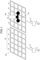
- Fig. 1 is an explanatory diagram showing a power transmission system 100 for a small mobile body 200.
- the power transmission system 100 is equipped with an AC power source 10, an AC power supply unit 20, and power transmission coils 81.
- the power transmission coils 81 are located at least in part of the range of movement of the small mobile body 200.
- the power transmission coils 81 are disposed on a plane in a 4 x 5 grid, constituting a coil unit 88.
- the AC power supply unit 20 and the power transmission coils 81 are connected by transmission line 70.
- the small mobile body 200 is, for example, a transport device that carries parts and other items in a factory.
- the small mobile body 200 has a power receiving coil 281 and uses the power receiving coil 281 to receive power wirelessly from the power transmission coil 81 and moves around the factory.
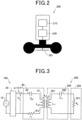
- Fig. 2 is an explanatory diagram showing the small mobile body 200.
- the small mobile body 200 has a battery 210, an AC power supply unit 220, and a power receiving coil 281.
- the power receiving coil 281 is electromagnetically coupled to the power transmission coil 81 and receives AC power from the power transmission coil 81.
- the AC power supply unit 220 converts the AC power received by the power receiving coil 281 into direct current.
- the AC power supply unit 220 for example, has a bridge rectifier circuit and a smoothing capacitor (not shown).
- the battery 210 stores power converted to direct current by AC power supply unit 220. The power stored in the battery 210 is used to power the small mobile body 200.
- Fig. 3 shows a schematic circuit diagram of the power transmission unit 80 of the power transmission system 100 and the power receiving unit 280 of the small mobile body 200.
- the power transmission unit 80 has a power transmission coil 81 connected in series with the AC power supply unit 20 and a capacitor 82.
- a resistor 81r in the circuit diagram in Fig. 3 is a parasitic resistance of the power transmission coil 81.
- the power receiving unit 280 has a power receiving coil 281 connected in series, a capacitor 282, and a load 221.
- the load 221 is the load of the small mobile body 200 and includes the load of the AC power supply unit 220 and the battery 210.
- an inductance of the power transmission coil 81 of the power transmission unit 80 is L g1
- a parasitic resistance is n
- a capacitance of the capacitor 82 is C g1
- a voltage effective value of the AC power supply unit 20 is V 1
- a transmission frequency is f
- n angular frequency is ⁇ .
- Each frequency ⁇ is 2 ⁇ f.
- an inductance of the power receiving coil 281 of the power receiving unit 280 is L v
- a capacitance of the capacitor 282 is C v
- an electrical resistance of the load 221 is R L .
- resonance means a state in which the voltage and current generated by the power transmission coil 81 or the power receiving coil 281 are larger than the voltage and current output from the AC power supply unit 20, when considered in terms of voltage and current amplitude. Or, it means a state in which an apparent power generated by the power transmission coil 81 and the power receiving coil 281 is larger than an apparent power at the output of the AC power supply unit 20.
- resonance means a state in which an imaginary component of the impedance of the transmission unit 80 decreases. Note that the imaginary component of the impedance of the transmission unit 80 may be zero.
- the impedance Z 1 is minimal.
- the imaginary component of the impedance of the power transmission coil 81 and the imaginary component of the impedance of the capacitor 82 are in opposite directions. That is, the imaginary component of the impedance of the power transmission coil 81 is positive. On the other hand, the imaginary component of the impedance of the capacitor 82 is negative. In the resonance state, the imaginary component of the positive impedance of the power transmission coil 81 and the imaginary component of the negative impedance of the capacitor 82 cancel each other, resulting in a smaller imaginary component of the impedance of the power transmission unit 80. Then, at a specific angular frequency ⁇ , the imaginary component of the impedance of the power transmission unit 80 from the power supply side becomes zero.
- k shown in Fig. 3 is a coupling coefficient. The following relationship exists between the coupling coefficient k and the mutual inductance L m .
- L m k ⁇ L g1 ⁇ Lv 1 / 2
- the coupling coefficient k is determined by the relative position of the power transmission coil 81 and the power receiving coil 281, and the larger the area of overlap between the power transmission coil 81 and the power receiving coil 281, the larger the coupling coefficient k. In other words, as the overlapping area of the power transmission coil 81 and the power receiving coil 281 increases, the coupling coefficient k also increases, and the magnitude of the mutual inductance L m also increases.
- Figs. 4A, 4B , and 4C are explanatory diagrams showing examples of configurations for changing the capacitance of the capacitor 82.
- the capacitor 82 has two capacitors 82a and 82b connected in parallel, and a switch 83, which is a capacitance modifier, is connected in series to the capacitor 82b.
- a switching control unit 85 acquires the voltage V 81 at both ends of the power transmission coil 81 using a voltage sensor 84 and drives the switch 83 to turn it on and off according to the value of the voltage V 81 .
- the switch 83 is turned on, the two capacitors 82a and 82b are connected in parallel, so the capacitance of the capacitor 82 is larger.
- a capacitance ratio of the capacitor 82 when the switch 83 is turned on and off is, for example, about 10 times greater, and more preferably about 100 times greater.
- the capacitance of the capacitor 82b should be about 9 or more times the capacitance of the capacitor 82a, more preferably about 99 times or more.
- the capacitances of the two capacitors 82a and 82b may be set so that the power transmission unit 80 resonances when the switch 83 is turned on, or so that the power transmission unit 80 resonances when the switch 83 is turned off, the capacitances of the two capacitors 82a and 82b may be set.
- the switch 83a may be used to switch which of the two capacitors 82a or 82b to be connected.
- two capacitors 82a and 82b may be connected in series, wiring may be provided to pass the capacitor 82b, and the switch 83c may be provided on the wiring passing the capacitor 82b.
- Mutual resonance means that when the power receiving coil 281 of the power receiving unit 280 approaches the power transmission coil 81, and the power transmission coil 81 and the power receiving coil 281 are coupled, they are in resonance. Whether the resonance is a single resonance or mutual resonance is determined by the inductance of the power transmission coil 81 and the capacitance of the capacitor 82.
- the impedance Z1 of the power transmission unit 80 is expressed by the following equation.
- Z 1 r 1 + j ⁇ L g1 + j ⁇ L m + 1 / j ⁇ C g1 .
- ⁇ L g1 -1/( ⁇ C g1 ) is not zero, the current I 1 through the power transmission unit 80 is reduced compared to the resonance state.
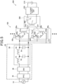
- Fig. 5 is an explanatory diagram showing a schematic configuration of a power transmission system 100 having a plurality of transmission units 80 and a small mobile body 200.
- the power transmission system 100 has an AC power source 10, an AC power supply unit 20, and the plurality of power transmission units 80.
- the power transmission units 80 are shown as transmission units 80a, 80b, and 80c.
- the AC power supply unit 20 is a device that generates AC voltage and supplies AC voltage to the power transmission unit 80.
- the AC power supply unit 20 has a power factor correction circuit 30, an inverter 40, and a filter 50.
- the power factor correction circuit 30 is a circuit that suppresses harmonic currents generated in the input current supplied from the AC power source 10 and brings the power factor close to 1.
- the inverter 40 converts DC voltage to AC at a predetermined frequency, for example, 85 kHz.
- he filter 50 has an L-type filter consisting of a coil 51 and a capacitor 52, and an L-type filter consisting of a coil 53 and a capacitor 54, both the L-type filters are connected in series.
- a plurality of power transmission units ..., 80a, 80b, 80c ... are connected in parallel to the AC power supply unit 20 as the power transmission units 80.
- the power transmission unit 80a has a power transmission coil 81a and a capacitor 82a connected in series.
- the power transmission unit 80b similarly has a power transmission coil 81b and a capacitor 82b connected in series.
- Other power transmission units, such as 80c, are similarly have power transmission coils and capacitors connected in series.
- the power transmission coil 81 is also referred to as "transmission coil 81" when there is no need to distinguish between the power transmission coils 81a, 81b, etc.
- the small mobile body 200 has a power receiving unit 280, an AC power supply unit 220, and a battery 210.
- the power receiving unit 280 has a power receiving coil 281 and a capacitor 282 connected in series.
- the power transmission coil 81a not only couples with the power receiving coil 281, but also with the adjacent power transmission coil 81b.
- the power transmission coil 81b not only couples with the power receiving coil 281, but also with the adjacent power transmission coils 81a and 81c.
- the power transmission coil 81c is a power transmission coil in the power transmission unit 80c, but is not shown in Fig. 5 for convenience of illustration.
- a coupling coefficient between the power transmission coil 81a and the power receiving coil 281 is kg1v
- a coupling coefficient between the power transmission coil 81b and the power receiving coil 281 is k g2v
- a coupling coefficient between the power transmission coil 81a and the adjacent power transmission coil 81b is k g1g2 .
- the coupling coefficient k g1g2 is determined by the relative position of the power transmission coils 81a and 81b, for example, relative distance. However, since the power transmission coils 81a and 81b are positioned and fixed in place, and the relative positions of the power transmission coils 81a and 81b do not change, the coupling coefficient k g1g2 , is a constant value.
- the relative distance is indicated, for example, by the distance between the centers of two coils.
- the coupling coefficient k g1v between the power transmission coil 81a and the power receiving coil 281 varies depending on the relative positions of the power transmission coil 81a and the power receiving coil 281. Therefore, the mutual inductance L ma between the power transmission coil 81a and the power receiving coil 281 also varies.
- the impedance of the power transmission unit 80a also varies due to the relative positions of the power transmission coil 81a and the power receiving coil 281, and the voltage V 81a at both ends of the power transmission coil 81a also varies.
- the mutual inductance L mb between the power transmission coil 81b and the power receiving coil 281 varies due the relative position of the power transmission coil 81b and the power receiving coil 281, which also varies the impedance of the power transmission unit 80b and the voltage V 81b at both ends of the power transmission coil 81b.
- Fig. 6 is an explanatory diagram showing the relationship between center positions of the power transmitting coils 81a, 81b, 81c and the power receiving coil 281 and the voltage of the transmitting coils 81a, 81b, 81c when the mobile body moves to the right.
- the voltages V 81a , V 81b , and V 81c in the upper graph show the voltages at both ends of the power transmission coils with the power transmission coils 81a, 81b, and 81c in resonance, respectively.
- the voltage Vn 81b in the lower graph shows the voltage at both ends of the power transmission coil 81b when the power transmission coil 81a is in resonance with the power receiving coil 281, but the power transmission coil 81b is not in resonance with the power receiving coil 281, i.e., non-resonance state.
- the voltage Vn 81c shows the voltage at both ends of the power transmission coil 81c when the power transmission coil 81b is in resonance with the power receiving coil 281, but the power transmission coil 81c is not in resonance with the power receiving coil 281, i.e., non-resonance state.
- the small mobile body 200 moves in the right direction in the figure.
- the center P281 of the power receiving coil 281 of the small mobile body 200 moves in the right direction in the figure, as ... P3, P4, ... P8 ....
- the power transmission coils 81a, 81b, and 81c are aligned in sequence along the direction of movement of the small mobile body 200, i.e., the direction of movement of the power receiving coil 281.
- Vn 81b k g1v ⁇ k g2v + k g1g2 ⁇ V 81a + Z 2 ⁇ I 2
- k g1v is the coupling coefficient between the power transmission coil 81a and the power receiving coil 281
- k g2v is the coupling coefficient between the power transmission coil 81b and the power receiving coil 28
- k g1g2 is the coupling coefficient between the power transmission coil 81a and the power receiving coil 81b
- Z 2 is the impedance of the power transmission unit 80b including the power transmission coil 81b
- I 2 is the current flowing in the power transmission coil 81b.
- the coupling coefficient K g1g2 is determined by the position of the power transmission coils 81a and 81b, and is a constant value regardless of the position of the power receiving coil 281.
- the coupling coefficients k g1v , k g2v , and voltage V 81a vary with the position of the power receiving coil 281. Note that since the power transmission coil 81b is not resonance, the current I 2 is small, and the second term in the above equation, Z 2 ⁇ I 2 , is smaller than the first term.
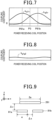
- Fig. 7 is an explanatory diagram showing the relationship between the position of the power receiving coil 281 and the coupling coefficients k g1v and k g2v between the power transmission coils 81a and 81b and the power receiving coil 281.
- the power transmission coils 81a and 81b are arranged so that the gap between the power transmission coils 81a and 81b is as small as possible, and the size of the power receiving coil 281 is large enough to span a plurality of power transmission coils, for example, the size of the power receiving coil 281 is large enough to span both of the power transmission coils 81a and 81b.
- the coupling coefficients k g1v and k g2v are positive maxima when the center P281 of the power receiving coil 281 is directly above the centers P81a and P81b of the transmitting coils 81a and 81b, respectively.
- the coupling coefficients k g1v and k g2v become smaller when the power transmission coils 81a and 81b are displaced from directly above the centers P81a and P81b. Note that if the center P281 of the power receiving coil 281 is greatly displaced from above the centers P81a and P81b of the transmitting coils 81a and 81b, the value may become negative.
- the power transmission coils 81a and 81b of the plurality of transmission units 80a and 80b are arranged so that the coupling coefficient between the power transmission coil 81 of at least one of the plurality of transmission units 80a and 80b and the power receiving coil 281, that is, at least one of the coupling coefficients k g1v and k g2v , is greater than zero, that is, positive.
- Fig. 8 is an explanatory diagram showing the relationship between the position of the power receiving coil 281 and the coupling coefficient k g1g2 between the two transmission coils 81a and 81b.
- the coupling coefficient k g1g2 since the coupling coefficient k g1g2 is determined by the position of the power transmission coils 81a and 81b, it becomes a constant value and does not change.
- the two power transmission coils 81a and 81b may be coupled through the power receiving coil 281. Therefore, the coupling coefficient k g1g2 is not a constant value and may vary slightly depending on the position of the power receiving coil 281.
- the small mobile body 200 moves to the right and the power receiving coil 281 also moves to the right.
- the power receiving coil 281 is between the power transmission coils 81a and 81b, and that the power transmission unit 80a including the power transmission coil 81a is in resonance state and the power transmission unit 80b including the power transmission coil 81b is in non-resonance state.
- the voltage Vn 81b of the power transmission coil 81b when the power transmission unit 80b is in a non-resonance state is greatest when the power receiving coil 281 is in the middle position P3 between the power transmission coil 81a and the power transmission coil 81b.
- the voltage Vn 81b of the power transmitting coil 81b becomes smaller.
- the voltage Vn 81b of the power transmission coil 81b becomes the threshold value Vnth.
- the switching control unit 85b switches the power transmission unit 80b including the power transmission coil 81b to the resonance state if the voltage Vn 81b of the power transmission coil 81b changes from above the threshold value Vnth to below the threshold value Vnth when the power transmission unit 80a is in the resonance state.
- the voltage V 81a of the power transmission coil 81a is below the threshold value Vth when the power receiving coil 281 reaches the position P5.
- the switching control unit 85a switches the power transmission unit 80a including the power transmission coil 81a to the non-resonance state when the voltage V 81a of the power transmission coil 81a is below the threshold value Vth.
- the voltage Vn 81c of the power transmission coil 81c is greatest when the power receiving coil 281 is at the middle position P6 between the power transmission coil 81b and the power transmission coil 81c.
- the voltage Vn 81c of the transmitting coil 81c becomes smaller.
- the voltage Vn 81c of the power transmission coil 81c becomes the threshold Vnth.
- the switching control unit 85c switches the power transmission unit 80c including the power transmission coil 81c to the resonance state if the voltage Vn81c of the power transmission coil 81c changes from above the threshold value Vnth to below the threshold value Vnth when the power transmission unit 80b is in the resonance state.
- the voltage V 81b of the power transmission coil 81b is below the threshold value Vth when the power receiving coil 281 reaches the position P8.
- the switching control unit 85b switches the power transmission unit 80b including the power transmission coil 81b to the non-resonance state when the voltage V 81b of the power transmission coil 81b is below the threshold value Vth.
- the power transmission unit 80a including the power transmission coil 81a is in resonance state and the power transmission unit 80b including the power transmission coil 81b is in non-resonance state.
- the voltage Vn 81b of the power transmission coil 81b when the power transmission unit 80b is in the non-resonance state is greatest when the power receiving coil 281 is at the middle position P6 between the power transmission coil 81c and the power transmission coil 81b.
- the voltage Vn 81b of the power transmitting coil 81b becomes smaller.
- the graph of the voltage Vn 81c shown in Fig. 6 becomes the graph of the voltage Vn 81b of the power transmission coil 81b
- the graph of the voltage Vn 81b becomes the graph of the voltage Vn 81a of the power transmission coil 81a.
- Fig. 9 shows a side view of the two power transmission coils 81a, 81b and the power receiving coil 281
- Fig. 10 shows a plan view of the two power transmission coils 81a, 81b and the power receiving coil 281.
- the two transmission coils 81a and 81b have substantially square shapes with one side length of a and are spaced ⁇ x apart.
- the distance between the centers of the power transmission coils 81a and 81b is a + ⁇ x.
- the power receiving coil 281 has a substantially square shape with one side length of 2a and moves ⁇ z higher from the two transmission coils 81a and 81b.
- Fig. 11 shows the relationship between the distance ⁇ x between the two transmission coils 81a and 81b and the coupling coefficient k g1g2 of the two transmission coils 81a and 81b.
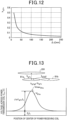
- Fig. 12 shows the relationship between the distance ⁇ z between the power transmission coil 81a and the power receiving coil 281 and the coupling coefficient k 1v between the power transmission coil 81a and the power receiving coil 281. Note that Fig. 12 shows a case where the center P281 of the power receiving coil 281 is positioned at P3, halfway between the two power transmission coils 81a and 81b.
- the coupling coefficient k g1g2 of the two transmission coils 81a and 81b becomes smaller as the distance ⁇ x between the two transmission coils 81a and 81b becomes larger, and it becomes larger as the distance ⁇ x becomes smaller.
- the coupling coefficient k 1v between the power transmission coil 81a and the power receiving coil 281 becomes smaller as the distance ⁇ z between the power transmission coil 81a and the power receiving coil 281 becomes larger, and it becomes larger as the distance ⁇ z becomes smaller. Therefore, these relationships can be used to obtain the desired coupling coefficients k g1g2 and k 1V .
- the values of the distance ⁇ x between the two transmission coils 81a and 81b and the distance ⁇ z in the z-direction between the power transmission coil 81a and the power receiving coil 281 can be determined. Note that as can be seen from Figs. 11 and 12 , the coupling coefficient k g1g2 of the power transmission coils 81a and 81b is smaller than the coupling coefficient k 1v between the power transmission coil 81a and the power receiving coil 281. This is because the magnetic flux through the power transmission coil 81a is directed in the ⁇ z direction, the magnetic flux of the power transmission coil 81a can easily pass through to the power receiving coil 281, which is in the +z direction.
- the power transmission coil 81b is located in the +x direction and has the same height in the z direction as the power transmission coil 81a, it is difficult for the magnetic flux passing through the power transmission coil 81a to pass through the power transmission coil 81b.
- Fig. 13 is an explanatory diagram showing a case of supplying power using a single transmission coil 81a.
- the coupling coefficient k g1g2 between the two power transmission coils 81a and 81b is determined from the distance ⁇ x between the two power transmission coils 81a and 81b, as described above. Once the distance ⁇ x between the two power transmission coils 81a and 81b is determined, the coupling coefficient k g1g2 between the two power transmission coils 81a and 81b becomes a constant value.
- the coupling coefficient k g1v between the power transmission coil 81a and the power receiving coil 281 varies depending on the position of the power receiving coil 281 relative to the power transmission coil 81a in the x and y directions, in addition to the distance ⁇ z in the z direction between the power transmission coil 81a and the power receiving coil 281.
- the coupling coefficient k g1v is maximal when the center of the power transmission coil 81a coincides with the center of the power receiving coil 281, and the more the center of the power receiving coil 281 shifts from the center of the power transmission coil 81a, the smaller the coupling coefficient k g1v .
- the coupling coefficient k g1v and the coupling coefficient k g1g2 satisfy the following equation. k g1g2 ⁇ k g1v
- V 81a Z 1 I 1 + j ⁇ L g1v I v
- the coupling coefficient k g1v between the power transmission coil 81a and the power receiving coil 281 is greater than the coupling coefficient k g1g2 between the two transmission coils 81a and 81b.
- the switching control unit 85a supplies power from the power transmission coil 81a to the power receiving coil 281 by setting the state of the first power transmission unit 80a to resonance state in the range where the coupling coefficient k g1v is greater than the coupling coefficient k g1g 2.
- the switching control unit 85a can stop supplying power from the power transmission coil 81a to the power receiving coil 281 by setting the state of the first power transmission unit 80a to a non-resonance state in the range where the coupling coefficient k g1v is less than the coupling coefficient k g1g2 .
- the switching control unit 85a can determine the strength of the magnetic flux penetrating the power transmission coil 81a and the power receiving coil 281 using the voltage V 81a of the power transmission coil 81a.
- the threshold value is set as the magnitude that exceeds the magnetic flux generated in the first power transmission coil 81a by the coupling between the first power transmission coil 81a and the second power transmission coil 81b, and the switching control unit 85a switches the state of the first power transmission unit 80a, which is one of the power transmission units, to the resonance state when the magnitude of the magnetic flux generated in the first power transmission coil 81a of the first power transmission unit 80a exceeds the predefined threshold value and switches to the non-resonance state when it is smaller than the threshold value.
- the threshold Vth for determining whether the state of the first power transmission unit 80a is resonance or non-resonance can be clarified.
- This threshold is set, for example, by the relative distance between the first power transmission coil 81A and the second power transmission coil 81B.
- the relative distance between the first power transmission coil 81A and the second power transmission coil 81B is the center-to-center distance between the center of the first power transmission coil 81A and the center of the second power transmission coil 81B.
- the switching control unit 85b switches the power transmission unit 80b including the power transmission coil 81b to the resonance state using the voltage Vn 81b of the power transmission coil 81b in the non-resonance state.
- the switching control unit 85a can switch the power transmission unit 80a including the power transmission coil 81a to the non-resonance state using the voltage Vn 81a of the power transmission coil 81a in the resonance state.
- the first embodiment uses one power transmission coil 81 to supply power
- the second embodiment differs in that it uses a plurality of power transmission coils 81 to supply power simultaneously.
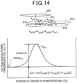
- Fig. 14 is an explanatory diagram showing a case of supplying power using four power transmission coils 81a, 81b, 81c, and 81d.
- the number of simultaneous power supplying is determined, for example, by an area ratio of the power transmission coils 81a, 81b, 81c, 81d to the area of the power receiving coil 281.
- the number of simultaneous power supplying coil is four, because the power receiving coil 281 has an area four times larger than that of the power transmission coil 81a.
- An area means, in each coil, the sum of the area inside the coil wiring portion and the area inside the coil wiring. Note that two or three power transmission coils, which are fewer than four, may be used to supply power simultaneously.
- the power transmission coil to be switched is called a first power transmission coil 81a
- the power transmission coils of the second power transmission units 80b, 80c, and 80d, which are adjacent to the first power transmission coil 81a and are supplying power are called second power transmission coils 81b, 81c, and 81d.
- the first power transmission coil 81a not only couples with the power receiving coil 281, but also with the second power transmission coils 81b, 81c and 81d.
- the coupling coefficient between the first power transmission coil 81a and the power receiving coil 281 is k g1v
- the coupling coefficients between the first power transmission coil 81a and the second power transmission coils 81b, 81c and 81d are k g1g2 , k g1g3 and k g1g4 respectively.
- the coupling coefficients k g1v , k g1g2 , k g1g3 , and k g1g4 satisfy the following equations. k g1g2 + k g1g3 + k g1g4 ⁇ k g1v
- the coupling relationship between the first power transmission coil 81a and the power receiving coil 281 is such that the coupling coefficient k g1v between the first power transmission coil 81a and the second power transmission coils 81b, 81c, 81d is greater than the sum of the coupling coefficients k g1g2 , k g1g3 and k g1g4 .
- the switching control unit 85a makes the state of the first power transmission unit 80a resonance in the range where the coupling coefficient k g1v is greater than the sum of the coupling coefficients k g1g2 , k g1g3 , and k g1g4 , and makes the state of the first power transmission unit 80a non-resonance in the range where the coupling coefficient kg1v is less than the sum of the coupling coefficients k g1g2 , k g1g3 , and k g1g4 .
- the threshold Vth for determining whether the state of the first power transmission unit 80a is resonance or non-resonance can be clarified.
- the first power transmission coil 81a can be switched in sequence to supply the power while maintaining a greater coupling between the first power transmission coil 81a and the power receiving coil 281 than between the first power transmission coil 81a and the second power transmission coils 81b to 81d.
- the voltage V 81a of the first power transmission coil 81a is expressed by the following equation using I 1 for the current flowing in the first power transmission coil 81a, I 2 , I 3 , and I 4 for the current flowing in the power second transmission coils 81b, 81c, and 81d, impedance Z 1 of the first power transmission unit 80a, and mutual inductances L g1g2 , L g1g3 , and L g1g4 between the first power transmission unit 80a and the second power transmission coils 81b, 81c, and 81d.
- V 81a Z 1 I 1 + j ⁇ L g1g2 I 2 + L g1g3 I 3 + L g1g4 I 4
- the minimum value Vmin 81a of the voltage V 81a of the first power transmission coil 81a occurs when the first power transmission coil 81a is coupled to the second power transmission coils 81b, 81c, 81d, but not to the power receiving coil 281.
- Fig. 15 compares the voltage V 81a of the first power transmission coil 81a in a case of one supplying coil and four supplying coils. If the minimum value Vmin 81a of the voltage V 81a of the first power transmission coil 81a when supplying power using four power transmission coils 81a to 81d is smaller than the maximum value Vmax 81a of the voltage V 81a of the first power transmission coil 81a when supplying power using one power transmission coil 81a, the voltage V 81a of the first power transmission coil 81a will exceed the maximum value Vmax 81a of the one supplying case somewhere as the center of the power receiving coil 281 moves.
- the switching control unit 85a can switch between the resonance and non-resonance states of the first power transmission coil 81a while maintaining a greater coupling between the first power transmission coil 81a and the power receiving coil 281 than between the first power transmission coil 81a and the second power transmission coils 81b to 81d.
- the switching control unit 85a can switch between the resonance and non-resonance states of the first power transmission unit 80a without being affected by changes in the respective currents I 1 , I 2 , I 3 , and I v due to misalignment.
- the above explanation describes a case in which four power transmission coils 81a-81d are used to supply four power transmission coils, but the number of power transmission coils may be other than four.
- the power transmission coil 81a is a hexagon with one side a, and the power transmission coils are arranged so that they are lined up in a honeycomb shape with six hexagonal power transmission coils 81b to 81g with one side a on each side of the power transmission coil 81a, seven coils are supplied.
- the voltage V 81a of the power transmission coil 81a is shown by the following equation.
- V 81a Z 1 I 1 + j ⁇ L g1g2 I 2 + j ⁇ L g1g3 I 3 + j ⁇ L g1g4 I 4 + j ⁇ L g1g5 I 5 + j ⁇ L g1g6 I 6 + j ⁇ L g1g7 I 7
- the shape of power transmission coils 81 is square, and when seven power transmission coils 81 are used, the shape of power transmission coils 81 is regular hexagonal, so that all power transmission coils 81 are the same shape and can be arranged without gaps.
- the plurality of power transmission units are disposed so that the coupling coefficient between the power transmission coil 81 of at least one of the plurality of power transmission units 80a and 80b, and the power receiving coil 281, that is, at least one of the coupling coefficients k g1v and k g2v , is zero or greater, that is, positive. Therefore, the switching control unit 85a places the state of the power transmission unit 80a in resonance when the power receiving coil 281 exists above the power transmission coil 81a and the coupling coefficient k g1v is positive, thus reducing the leakage of the magnetic flux of the power transmission coil 81a to other than the power receiving coil 281. The same is true for the magnetic flux of the power transmission coil 81b.
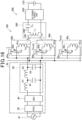
- Fig. 16 is an explanatory diagram showing a schematic configuration of a power transmission unit 100 having a plurality of power transmission units 80 and a small mobile body 200 in the third embodiment.
- the configuration of the third embodiment is almost the same as that of the first embodiment, but differs from the first embodiment in the following points.
- the non-power transmission state means a state in which the magnetic flux generated by the first power transmission coil 81a is below the standard value for human exposure that does not affect humans, as specified by the International Commission on Non-Ionizing Radiation Protection (ICNIRP), for example. In this state, sufficient power cannot be transmitted from the first power transmission coil 81a to the power receiving coil 282.
- the power transmission state means a state in which sufficient magnetic flux can be generated in the first power transmission coil 81a to supply sufficient power to the power receiving coil 282. Since the magnetic flux in this power transmission state can affect people, the power transmission system 100 is used, for example, in unmanned factories. In a manned factory, the effect of magnetic flux on people may be suppressed by having people work in magnetically shielded areas.
- Switching the state of the power transmission unit 80a to the resonance state means changing the capacitance C g1 of a capacitor 82 so that an imaginary component j ⁇ L m + 1/(j ⁇ C g1 ) of the following equation for the impedance of the power transmission unit 80a becomes zero.
- Z 1 r 1 + j ⁇ L m + 1 / j ⁇ C g1
- switching the state of the power transmission unit 80a to the power transmission state means changing the capacitance C g1 of the capacitor 82 so that the magnitude of the imaginary component j ⁇ L m + 1/(j ⁇ C g1 ) in the above equation is less than a predetermined magnitude. Therefore, whether the power transmission unit 80a is switched to the resonance state or the power transmission state, the capacitance C g1 of the capacitor 82 is changed in the same way.
- the range of capacitance C g1 of capacitor 82 is wider in the power transmission state than in the resonance state, and the relationship is that if the state of the power transmission unit 80a is resonance, it will be in the power transmission state, but not necessarily in the resonance state.
- the power transmission coil 81a magnetically couples with the adjacent power transmission coil 81b as well as with the distant power transmission coil 81c with the adjacent power transmission coil 81b in between, as shown in Fig. 16 .
- the relationship is that adjacent power transmission coils are magnetically coupled, but even magnetically coupled power transmission coils are not necessarily adjacent power transmission coils.
- the threshold value for when the switching control unit 85 switches the state of the power transmission unit 80a to the power transmission or non-power transmission state is set as a magnitude that exceeds the magnetic flux generated in the first power transmission coil 81a by the coupling between the first power transmission coil 81a and the second power transmission coil 81b in at least one or more second power transmission units 80b that magnetically couple to the first power transmission coil 81a.
- the coupling coefficient k g1g3 between the power transmission coil 81a and the power transmission coil 81c is very much smaller than the coupling coefficient k g1g2 between the power transmission coil 81a and the power transmission coil 81b.
- the coupling coefficient with the non-adjacent power transmission coil 81c is extremely smaller than the coupling coefficient with the adjacent power transmission coil 81b. Therefore, although the non-adjacent power transmission coil 81c is magnetically coupled to the power transmission coil 81a, the magnetic flux generated in the power transmission coil 81a due to coupling with the power transmission coil 81c is very small. Therefore, as in the third embodiment, it is preferable to set the threshold value as a magnitude that exceeds the magnetic flux generated in the first power transmission coil 81a by the coupling between the first power transmission coil 81a and the second power transmission coil 81b of at least one or more second power transmission units 80b that are magnetically coupled to the first power transmission coil 81a.
- the second power transmission coil may be the power transmission coil 81b, which does not include the power transmission coil 81c and is adj acent to the first power transmission coil 81a.
- This threshold is set, for example, by the relative distance between the first power transmission coil 81a and the second power transmission coil 81b.
- the relative distance between the first power transmission coil 81a and the second power transmission coil 81B is the center-to-center distance between the center of the first power transmission coil 81a and the center of the second power transmission coil 81b.
- the switching control unit 85a switches the state of the first power transmission unit 80a to the power transmission state when the magnitude of the magnetic flux generated in the first power transmission coil 81a of the first power transmission unit 80a, which is one of the power transmission units, exceeds a predetermined threshold value, and switches to the non-power transmission state when it is smaller than the threshold value, thus enabling more appropriate switching control between the power transmission and the non-power transmission.
- the threshold is set as a magnitude that exceeds the magnetic flux generated in the first power transmission coil 81a by the coupling of the first power transmission coil 81a and the second power transmission coil 81b of at least one or more second power transmission units 80b that are magnetically coupled to the first power transmission coil 81a, so that the first power transmission unit 80a can more accurately switch between the power transmission state and the non-power transmission state.
- the threshold of the third embodiment may be used in switching between resonance and non-resonance states in the first embodiment, and the threshold of the first embodiment may be used in switching between the power transmission state and the non-power transmission state in the third embodiment.
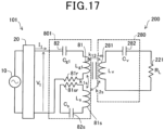
- Fig. 17 shows a schematic circuit diagram of a power transmission unit 801 of a power transmission system 101 and a power receiving unit 280 of a small mobile body 200 in the fourth embodiment.
- the power transmission unit 801 uses a split-coil resonance system in which the power transmission coil is divided into a power transmission coil 81 and a power transmission coil 81s, and a capacitor is also divided into capacitors 82 and 82s.
- the power transmission coil 81 and the capacitor 82 are connected in series, and the power transmission coil 81s and the capacitor 82s are connected in series. Note that the circuit configuration of the small mobile body 200 is the same in both the first and fourth embodiments.
- an inductance of the power transmission coil 81 is L g1
- an inductance of the power transmission coil 81s is L s
- a capacitance of capacitor 82 is C g1
- a capacitance of capacitor 82s is C s
- an inductance of a power receiving coil 282 is L v
- a capacitance of a capacitor 282 is C v
- a coupling coefficient between the power transmission coil 81s and the power transmission coil 81 is k 1s
- a coupling coefficient between the power transmission coil 81 and a power receiving coil 281 is k 12
- a coupling coefficient between the power transmission coil 81s and the power receiving coil 281 is ks 2 .
- the capacitance C g1 of the capacitor 82 and the capacitance C s of the capacitor 82s for the power transmission unit 801 to be in resonance alone are the same as in the first embodiment, respectively, and are as follows.
- C g1 1 / ⁇ 2 L g1
- C s 1 / ⁇ 2 L s
- I 1 k s2 / k 1s 2 L v / L 1g V 1 / R L
- the current I 0 when the power transmission coils 81, 81s and the power receiving coil 281 are not coupled is smaller than the current I 1 flowing in the power transmission coil 81 when the power transmission coils 81, 81 s and the power receiving coil 281 are resonance or coupled because resonance is broken and the impedance Z 1 is larger.
- the magnetic flux generated by the power transmission coil 81 and passing through the power receiving coil 282 is larger in the resonance or coupled state.
- the current flowing through the power transmission coil 81 can be increased to increase the amount of magnetic flux transmitted through the power receiving coil 282, while when the power receiving coil 281 is further away from the power transmission coil 81, the current flowing through the power transmission coil 81 can be reduced.
- Fig. 18 is an explanatory diagram showing a power transmission system 100 for a small mobile body in the fifth embodiment.
- the power transmission system 100 transmits power to a single small mobile body 200, however, in the fifth embodiment, the power transmission system 100 transmits power to a plurality of small mobile bodies 200 and 200x.
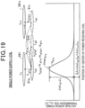
- Fig. 19 is an explanatory diagram showing the fifth embodiment of supplying power from one power transmission coil 81a to two small mobile bodies 200 and 200x.
- three power transmission coils 81a, 81b, 81x and two power receiving coils 281, 281x are shown.
- Inductances of the three power transmission coils 81a, 81b, and 81x are L g1 , L g2 , and L gx , respectively.
- inductances of the power receiving coils 281 and 281x of the small mobile bodies 200 and 200x are L v and L vx , respectively.
- a coupling coefficient between the power transmission coil 81a and the power transmission coil 81b is k g1g2
- coupling coefficients between the power transmission coil 81a and the power receiving coils 281 and 281x are k g1v1 and k g1vx , respectively.
- a coupling coefficient between the power transmission coil 81a and the power receiving coil 281x via the power transmission coil 81x is k g1gvx .
- V 81a Z 1 I 1 + j ⁇ L g 1 v I v + j ⁇ L gx I gx + j ⁇ L vx I vx
- the state of the first power transmission unit 80a when supplying power, is the power transmission state in the range where the coupling coefficient kg1v1 between the first power transmission coil 81a and the power receiving coil 281 is greater than the sum of the coupling coefficients k g1g2 , k g1vx , and k g1gvx , and the state of the first power transmission unit 80a is the non-power transmission state in the range where the coupling coefficient kg1v1 is less than the sum of the coupling coefficients k g1g2 , k g1gvx , and k g1vx .
- the switching control unit 85a can determine the strength of the magnetic flux penetrating the power transmission coil 81a and the power receiving coil 281 using the voltage V 81a of the power transmission coil 81a.
- the switching control unit 85a switches the state of the first power transmission unit 80a to the resonance state when the magnitude of the magnetic flux generated in the first power transmission coil 81a of the first power transmission unit 80a, which is one of the power transmission units, is greater than a predetermined threshold value, and switches to the non-resonance state when it is less than the threshold value.
- the threshold Vth can be used to determine whether the state of the first transmission unit 80a is a transmission state or a non-power transmission state.
- Fig. 20 is an explanatory diagram showing the fifth embodiment, in which four power transmission coils supply two small mobile bodies 200 and 200x.
- five power transmission coils 81a, 81b, 81c, 81d, 81x and two power receiving coils 281 and 281x are shown.
- Inductances of the five power transmission coils 81a, 81b, 81c, 81d, and 81x are L g1 , L g2 , L g3 , L g4 , and L gx , respectively.
- inductances of the power receiving coils 281 and 281x of the small mobile bodies 200 and 200x are L v and L vx , respectively.
- Coupling coefficients between the power transmission coil 81a and the power transmission coils 81b, 81c, and 81d are k g1g2 , k g1g3 , and k g1g4 , and coupling coefficients between the power transmission coil 81a and the power receiving coils 281 and 281x are k g1v1 and k g1vx , respectively.
- a coupling coefficient between the power transmission coil 81a and the power receiving coil 281x via the power transmission coil 81x is k g1gvx .
- the coupling coefficients k g1v1 , k g1g2 , k g1g3 , k g1g4 , k g1vx , and k g1gvx satisfy the following equation. k g 1 g 2 + k g 1 g 3 + k g 1 g 4 + k g 1 gvx + k g 1 vx ⁇ k g 1 v 1
- V 81a Z 1 I 1 + j ⁇ L g 1 g 2 I 2 + L g 1 g 3 I 3 + L g 1 g 4 I 4 + L gx I gx + L vx I vx
- j ⁇ L gx I gx + j ⁇ L vx I vx increases by the number of small mobile bodies 200x.
- the small mobile body 200 may have a plurality of power receiving coils.
- the concept for a case where the small mobile body 200 has a plurality of power receiving coils is the same as for the case where there are a plurality of small mobile bodies, where j ⁇ L gx I gx + j ⁇ L vx I vx increases by the number of power receiving coils.
- the state of the first power transmission unit 80a when supplying power, is the power transmission state in the range where the coupling coefficient k g1v1 between the first power transmission coil 81a and the power receiving coil 281 is greater than the sum of the coupling coefficients k g1g2 , k g1g3 , k g1g4 , k g1gvx and k g1vx.
- the state of the first power transmission unit 80a is the non-power transmission state in a range where the coupling coefficient k g1v1 is less than or equal to the sum of the coupling coefficients k g1g2 , k g1g3 , k g1g4 , k g1gvx and k g1vx ,.
- the switching control unit 85a can determine the strength of the magnetic flux penetrating the power transmission coil 81a and the power receiving coil 281 using the voltage V 81a of the power transmission coil 81a.
- the switching control unit 85a switches the state of the first power transmission unit 80a to the resonance state when the magnitude of the magnetic flux generated in the first power transmission coil 81a of the first power transmission unit 80a, which is one of the power transmission units, is above a predetermined threshold value, and switches to the non-resonance state when it is below the threshold value.
- the threshold Vth for determining whether the state of the first transmission unit 80a is the transmission state or the non-power transmission state can be used.
- Fig. 21 is an explanatory diagram showing a case where power transmission coils 81 are aligned in the x direction.
- the above embodiments described the example in which a plurality of transmission coils 81 are arranged in a grid pattern.
- the power transmission coils 81 are aligned in the x direction, and a small mobile body 200 moves in the x direction.
- the plurality of transmission coils 81 aligned in the x direction can transmit power sequentially as a power receiving coil 281 of the small mobile body 200 moves in the x direction.
- this sequence of transmitting coils 81 allows a simple continuous power supply from the plurality of transmitting coils 81 to the power receiving coil 281.
- Fig. 22 is an explanatory diagram showing another arrangement of transmission coils 81.
- An example shown in Fig. 22 has the power transmission coils 81 arranged in a line in the x-direction and the power transmission coils 81 arranged in a two-dimensional grid in the x- and y-directions.
- the power transmission coils 81 can be freely arranged to suit the layout of the factory.
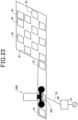
- Fig. 23 is an explanatory diagram showing yet another arrangement of power transmission coils 81.
- power transmission coils 81 are arranged except for some power transmission coils 81 from the example shown in Fig. 22 .
- the arrangement shown in Fig. 23 is one in which the power transmission coil 81 is located according to the power supply plan from the power transmission coil 81 to the power receiving coil 281.
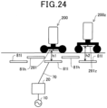
- Fig. 24 shows an example of changing the depth at which the power transmission coils 81 are located.
- the example shown in Fig. 24 shows a transmission coil 81h located at a shallow location on the ground plane and a transmission coil 81I located at a deeper location.
- two small mobile bodies 200 and 200z are shown. The ground height of a power receiving coil 281 of a small mobile body 200 is lower and the ground height of a power receiving coil 281z of a small mobile body 200z is higher.
- the distance between the deeply located transmission coil 81l and the power receiving coil 281 of the small mobile body 200 is h1, and as shown in Fig. 12 , a coupling coefficient between the power transmission coil 811 and the power receiving coil 281 can be large, therefore, enough power can be transmitted from the power transmission coil 811 to the power receiving coil 281.
- the distance between the deeply located transmission coil 81l and the power receiving coil 281z of the small mobile body 200z is h2, and as shown in Fig. 12 , the coupling coefficient between the power transmission coil 81l and the power receiving coil 281z cannot be increased, therefore, sufficient power cannot be transmitted.
- the coupling coefficient between the power transmission coil 81h and the power receiving coils 281, 281z can be increased and sufficient power can be transmitted to the power receiving coils 281, 281z.
- the example shown in Fig. 24 allows for the mixing of a plurality of small mobile bodies 200 and 200z with different heights of power receiving coils 281 and 281z. Further, for the small mobile body 200 with a low ground clearance of the power receiving coil 281, power is supplied from both power transmission coils 81l and 81h, and for the small mobile body 200z with a high ground clearance of the power receiving coil 281z, power is supplied from the power transmission coil 81h. As a result, the number of power supplying frequent to the small mobile body 200 with low ground clearance of the power receiving coil 281 can be increased.
- Fig. 25 is an explanatory diagram showing an example of different size, number of turns, and shape of power transmission coils depending on a location of power transmission coils.
- a power transmission coil 81S located to the left of a power transmission coil 81 is smaller in size than the power transmission coil 81. Therefore, a coupling coefficient when the power transmission coil 81s couples with a power receiving coil 281 becomes smaller. As a result, the amount of power supplied from the transmitting coil 81s to the power receiving coil 281 is small.
- a power transmission coil 81m located to the left of the power transmission coil 81 is the same size as the power transmission coil 81, but has more turns. Therefore, a coupling coefficient of the power transmission coil 81m coupling to the power receiving coil 281 is larger. As a result, the amount of power supplied from the power transmission coil 81m to the power receiving coil 281 is large.
- the amount of power supplied from the power transmission coil 81m to the power receiving coil can be changed.
- a power transmission coil 81e located to the right of the power transmission coil 81m has a circular shape. If the wiring lengths of the power transmission coils are the same, the power transmission coil 81e with the circular shape can have a larger area inside the power transmission coil than the rectangular power transmission coil 81. Therefore, when the wiring lengths of the power transmission coils are the same, a coupling coefficient of the power transmission coil 81e can be larger than that of the power transmission coil 81, and the amount of power supplied can be larger. Note that if the power transmission coil is a rectangular power transmission coil 81, it is easy to arrange the power transmission coils 81 without gaps in the area where the power transmission coils are located. As a result, an area where the power receiving coil 281 does not overlap with the power transmission coil 81 can be reduced.
- the voltage of the power transmission coil 81a is used to determine the coupling between the power transmission coil 81a and the power receiving coil 281, the power transmission coil 81a and the power transmission coil 81b, etc.
- the current flowing in the power transmission coil 81a may be used to determine the coupling between the power transmission coil 81a and the power receiving coil 281, the power transmission coil 81a and the power transmission coil 81b, etc.
- the impedance of the power transmission unit 80 is switched between the resonance and non-resonance states, or between the power transmission and non-power transmission states, by switching the capacitance of the capacitor 82
- the impedance may be configured to switch between the resonance and non-resonance states, or between the power transmission and non-power transmission states, of the power transmission unit 80 by switching the inductance of the power transmission coil 81.
- a variable capacitor may be used as a capacitor 82.
- the capacitance of a capacitor may be changed by changing the distance between two pole plates that constitutes the capacitor, using the force due to the magnetic flux received by the capacitor.
- the capacitors 82a and 82b are connected in parallel, they may be configured to be connected in series.
- the capacitors 82a and 82b are used as the capacitors 82, three or more capacitors may be used and the number of capacitors connected in series or in parallel may be switched.
- the switch 83 may be a physical connection or disconnection switch, such as a relay, or an electrical connection or disconnection switch, such as a semiconductor switch.
- the number of coils connected may be switched by a switch, or a variable inductor that can change the magnitude of inductance may be used.
- a coil in which the permeability of the core material changes may be used as a variable inductor.
- the switch may change the number of coil turns, or a plurality of coils may be connected in series or parallel, and the switch may change the number of coils connected.
- the switch may be a physical connection or disconnection, such as a relay, or an electrical connection or disconnection, such as a semiconductor switch.
- a variable resistor may be disposed in the power transmission circuit 80 and the impedance may be changed by changing an electrical resistance of the variable resistor.
- the electrical resistance of the variable resistor is the real component of impedance.
- the variable resistor has a mechanism to vary the length and width of an internal resistive element.
- a potentiometer may be used as a variable resistor, for example.
- a plurality of resistors may be arranged in series or parallel, and a switch may be used to switch the number of resistors connected to the power transmission circuit 80. Similar to switching the capacitance of a capacitor or switching the inductance of a coil, this switch may be physically connected or disconnected, such as a relay, or electrically connected or disconnected, such as a semiconductor switch.
- variable capacitor, the variable inductor, and the variable resistor are examples of variable impedance devices, and at least one of the variable impedance devices may be used to change the impedance of the power transmission circuit 80 to switch between the resonance and non-resonance states, or between the power transmission and non-power transmission states.
- magnetic flux is measured indirectly by measuring the voltage and current of the power transmission coil
- magnetic flux may also be measured using a magnetic sensor such as a Hall sensor.
- the present disclosure can be realized in various forms, and for example, addition to a wireless power supply system, it can be realized in the form of a power transmission device or the like.
- the present disclosure is not limited to the embodiments described above, but can be realized in various configurations to the extent that the scop is not departed from.
- the technical features of the embodiments corresponding to the technical features in each of the embodiments described in the Summary of the Invention section can be replaced or combined as appropriate to solve some or all of the above issues or to achieve some or all of the above effects.
- the technical feature is not described as essential in the specification, it can be deleted as appropriate.
Landscapes
- Engineering & Computer Science (AREA)
- Computer Networks & Wireless Communication (AREA)
- Power Engineering (AREA)
- Physics & Mathematics (AREA)
- Electromagnetism (AREA)
- Current-Collector Devices For Electrically Propelled Vehicles (AREA)
Abstract
Description
- This application is based on and claims the benefit of priority from earlier
Japanese Patent Application No. 2021-090830 filed on May 31, 2021 Japanese Patent Application No. 2022-035987 filed on March 9, 2022 - The present disclosure relates to a wireless power supply system.
-
JP 2019-71719 A - However, a coupling between a plurality of power transmission coils was not considered in the wireless power supply system for mobile bodies described in
JP 2019-71719 A - According to an aspect of the present disclosure, there is provided a wireless power supply system for a mobile body equipped with a power receiving unit having a power receiving coil. The wireless power supply system includes an AC power supply unit and a plurality of power transmission units, the plurality of power transmission units are disposed in at least a part of a moving range of the moving body and include a power transmission coil. The wireless power supply system includes a plurality of power transmission units that receive a supply of power from the AC power supply unit and supply power to a power receiving unit via the power transmission coil in a resonance state, and a switching control unit that switches a state of a first power transmission unit to a resonance state when the magnitude of the magnetic flux generated in a first power transmission coil of the first power transmission unit, which is one of the plurality of power transmission units, is greater than a predetermined threshold value, and switches to a non-resonance state when the magnitude is less than the threshold value. The threshold is set as a magnitude that exceeds the magnetic flux generated in the first power transmission coil due to a coupling between the first power transmission coil and a second power transmission coil of a second power transmission unit, which is adj acent to the first power transmission coil. According to this aspect, the switching control unit can supply power to the power receiving unit by switching the resonance state of the plurality of power transmission units in sequence by setting the threshold value appropriately and setting the state of the first power transmission unit to resonance or non-resonance according to the magnitude of the magnetic flux passing through the first power transmission coil.
- The above and other objects, features and advantages of the present disclosure will be made clearer by the following detailed description with reference to the accompanying drawings. The drawings are:
-
Fig. 1 is an explanatory diagram showing a power transmission system for a small mobile body; -
Fig. 2 is an explanatory diagram showing the small mobile body; -
Fig. 3 is a schematic circuit diagram of a power transmission unit of the power transmission system and a power receiving unit of the small mobile body; -
Fig. 4A is an explanatory diagram showing an example of a configuration for changing the capacitance of a capacitor; -
Fig. 4B is an explanatory diagram showing another example of a configuration for changing the capacitance of a capacitor; -
Fig. 4C is an explanatory diagram showing yet another example of a configuration for changing the capacitance of a capacitor; -
Fig. 5 is an explanatory diagram showing a schematic configuration of a power transmission system having a plurality of power transmission units and a small mobile body; -
Fig. 6 is an explanatory diagram showing the relationship between center positions of the power transmission coils and the power receiving coil and the voltage of the power transmission coils when the mobile body moves to the right; -
Fig. 7 is an explanatory diagram showing the relationship between the position of the power receiving coil and the coupling coefficient between the power transmission coil and the power receiving coil; -
Fig. 8 is an explanatory diagram showing the relationship between the position of the power receiving coil and the coupling coefficient between the two power transmission coils; -
Fig. 9 is a side view showing the two power transmission coils and the power receiving coil; -
Fig. 10 is a plan view showing two power transmission coils and the power receiving coil; -
Fig. 11 is a graph showing the relationship between a distance between two power transmission coils and the coupling coefficient of the two power transmission coils; -
Fig. 12 is a graph showing the relationship between the distance between the power transmission coil and the power receiving coil and the coupling coefficient between the power transmission coil and the power receiving coil; -
Fig. 13 is an explanatory diagram showing a case where power is supplied using a single power transmission coil; -
Fig. 14 is an explanatory diagram showing a case where power is supplied using four power transmission coils; -
Fig. 15 is an explanatory diagram comparing the voltage of the first power transmission coil in the case of a single power supply coil and four power supply coils; -
Fig. 16 is an explanatory diagram showing a schematic configuration of a power transmission system having a plurality of power transmission units and a small mobile body in a third embodiment; -
Fig. 17 is a schematic circuit diagram of a power transmission system of a power transmission system and a power receiving unit of a small mobile body in a fourth embodiment; -
Fig. 18 is an explanatory diagram showing a power transmission system for small mobile bodies in a fifth embodiment; -
Fig. 19 is an explanatory diagram when power is supplied to two small mobile bodies from a single power transmission coil in the fifth embodiment; -
Fig. 20 is an explanatory diagram when power is supplied to two small mobile bodies from four power transmission coils in the fifth embodiment; -
Fig. 21 is an explanatory diagram showing a case where power transmission coils are lined up in a straight line in an x direction; -
Fig. 22 is an explanatory diagram showing another arrangement of power transmission coils; -
Fig. 23 is an explanatory diagram showing yet another arrangement of power transmission coils; -
Fig. 24 is an example in which the depth at which the power transmission coil is disposed is varied; and -
Fig. 25 is an explanatory diagram showing an example in which the size, number of turns, and shape of the power transmission coil are varied depending on a placement location of the power transmission coil. -
Fig. 1 is an explanatory diagram showing apower transmission system 100 for a smallmobile body 200. Thepower transmission system 100 is equipped with anAC power source 10, an ACpower supply unit 20, andpower transmission coils 81. In the present embodiment, thepower transmission coils 81 are located at least in part of the range of movement of the smallmobile body 200. In the example shown inFig. 1 , thepower transmission coils 81 are disposed on a plane in a 4 x 5 grid, constituting acoil unit 88. The ACpower supply unit 20 and thepower transmission coils 81 are connected bytransmission line 70. The smallmobile body 200 is, for example, a transport device that carries parts and other items in a factory. The smallmobile body 200 has a power receivingcoil 281 and uses thepower receiving coil 281 to receive power wirelessly from thepower transmission coil 81 and moves around the factory. -
Fig. 2 is an explanatory diagram showing the smallmobile body 200. The smallmobile body 200 has abattery 210, an ACpower supply unit 220, and apower receiving coil 281. The power receivingcoil 281 is electromagnetically coupled to thepower transmission coil 81 and receives AC power from thepower transmission coil 81. The ACpower supply unit 220 converts the AC power received by thepower receiving coil 281 into direct current. The ACpower supply unit 220, for example, has a bridge rectifier circuit and a smoothing capacitor (not shown). Thebattery 210 stores power converted to direct current by ACpower supply unit 220. The power stored in thebattery 210 is used to power the smallmobile body 200. -
Fig. 3 shows a schematic circuit diagram of thepower transmission unit 80 of thepower transmission system 100 and thepower receiving unit 280 of the smallmobile body 200. Thepower transmission unit 80 has apower transmission coil 81 connected in series with the ACpower supply unit 20 and acapacitor 82. Aresistor 81r in the circuit diagram inFig. 3 is a parasitic resistance of thepower transmission coil 81. Thepower receiving unit 280 has apower receiving coil 281 connected in series, acapacitor 282, and aload 221. Theload 221 is the load of the smallmobile body 200 and includes the load of the ACpower supply unit 220 and thebattery 210. - Here, an inductance of the
power transmission coil 81 of thepower transmission unit 80 is Lg1, a parasitic resistance is n, a capacitance of thecapacitor 82 is Cg1, a voltage effective value of the ACpower supply unit 20 is V1, a transmission frequency is f, and n angular frequency is ω. Each frequency ω is 2πf. In addition, an inductance of thepower receiving coil 281 of thepower receiving unit 280 is Lv, a capacitance of thecapacitor 282 is Cv, and an electrical resistance of theload 221 is RL. - A case where each of the
power transmission units 80 andpower receiving units 280 resonance independently will be considered. When thepower transmission coil 81 and thecapacitor 82 are connected in series, resonance means a state in which the voltage and current generated by thepower transmission coil 81 or thepower receiving coil 281 are larger than the voltage and current output from the ACpower supply unit 20, when considered in terms of voltage and current amplitude. Or, it means a state in which an apparent power generated by thepower transmission coil 81 and thepower receiving coil 281 is larger than an apparent power at the output of the ACpower supply unit 20. In addition, if it is considered that resonance in terms of impedance, resonance means a state in which an imaginary component of the impedance of thetransmission unit 80 decreases. Note that the imaginary component of the impedance of thetransmission unit 80 may be zero. - The impedance Z1 of the
power transmission unit 80 is expressed by the following equation:
- In the resonance state, the imaginary component of the impedance Z1 decreases.
- If the imaginary component of the impedance Z1 is zero, the impedance Z1 is minimal.
- That is:

- Or, bracket the left side of the above equation with j, it becomes:

- As can be seen from the equation bracketed by j, the imaginary component of the impedance of the
power transmission coil 81 and the imaginary component of the impedance of thecapacitor 82 are in opposite directions. That is, the imaginary component of the impedance of thepower transmission coil 81 is positive. On the other hand, the imaginary component of the impedance of thecapacitor 82 is negative. In the resonance state, the imaginary component of the positive impedance of thepower transmission coil 81 and the imaginary component of the negative impedance of thecapacitor 82 cancel each other, resulting in a smaller imaginary component of the impedance of thepower transmission unit 80. Then, at a specific angular frequency ω, the imaginary component of the impedance of thepower transmission unit 80 from the power supply side becomes zero. The capacitance Cg1 of thecapacitor 82 for which thepower transmission unit 80 is in a resonance state by itself and the imaginary component of the impedance becomes zero is Cg1 = 1/(ω2Lg1) - The current I1 flowing in the
power transmission unit 80 at this time is extreme and I1 = V1/r1. - Similarly, in the
power receiving unit 280, the capacitance C1 of thecapacitor 282 for which the power receiving unit 280is in a resonance state by itself and the imaginary component of impedance becomes zero is C1 = 1/(ω2Lv). - As the small
mobile body 200 moves and thepower receiving coil 281 of thepower receiving unit 280 approaches thepower transmission coil 81, thepower transmission coil 81 and thepower receiving coil 281 couple, and the inductance of thepower transmission coil 81 changes. If a mutual inductance at coupling is Lm, the impedance Z1 of thepower transmission unit 80 is Z1 = {r1 + jωLm + 1/(jωCg1)}. If the capacitance Cg1 ofcapacitor 82 is set so that jωLm + 1/(jωCg1) approaches zero, resonance can be maintained. Note that k shown inFig. 3 is a coupling coefficient. The following relationship exists between the coupling coefficient k and the mutual inductance Lm.
- The coupling coefficient k is determined by the relative position of the
power transmission coil 81 and thepower receiving coil 281, and the larger the area of overlap between thepower transmission coil 81 and thepower receiving coil 281, the larger the coupling coefficient k. In other words, as the overlapping area of thepower transmission coil 81 and thepower receiving coil 281 increases, the coupling coefficient k also increases, and the magnitude of the mutual inductance Lm also increases. - When the
power transmission coil 81 and thepower receiving coil 281 are coupled and in resonance state, if the output voltage of the ACpower supply unit 20 is V1, the current I1 of thepower transmission unit 80 is indicated by the following equation.
-
Figs. 4A, 4B , and4C are explanatory diagrams showing examples of configurations for changing the capacitance of thecapacitor 82. In the example shown inFig. 4A , thecapacitor 82 has twocapacitors switch 83, which is a capacitance modifier, is connected in series to thecapacitor 82b. A switchingcontrol unit 85 acquires the voltage V81 at both ends of thepower transmission coil 81 using avoltage sensor 84 and drives theswitch 83 to turn it on and off according to the value of the voltage V81. When theswitch 83 is turned on, the twocapacitors capacitor 82 is larger. On the other hand, when theswitch 83 is turned off, only thecapacitor 82a is connected, so the capacitance of thecapacitor 82 is only that of thecapacitor 82a and is smaller than when theswitch 83 is turned on. A capacitance ratio of thecapacitor 82 when theswitch 83 is turned on and off is, for example, about 10 times greater, and more preferably about 100 times greater. To achieve the capacitance ratio of about 10 or even 100 times, for example, the capacitance of thecapacitor 82b should be about 9 or more times the capacitance of thecapacitor 82a, more preferably about 99 times or more. Note that the capacitances of the twocapacitors power transmission unit 80 resonances when theswitch 83 is turned on, or so that thepower transmission unit 80 resonances when theswitch 83 is turned off, the capacitances of the twocapacitors Fig. 4B , theswitch 83a may be used to switch which of the twocapacitors Fig. 4C , twocapacitors capacitor 82b, and theswitch 83c may be provided on the wiring passing thecapacitor 82b. In this case, when theswitch 83c is turned on, only thecapacitor 82a is connected. On the other hand, whenswitch 83c is turned off, thecapacitors capacitor 82 is smaller than when theswitch 83c is turned on. - Next, a case of mutual resonance in
Fig. 3 will be considered. Mutual resonance means that when thepower receiving coil 281 of thepower receiving unit 280 approaches thepower transmission coil 81, and thepower transmission coil 81 and thepower receiving coil 281 are coupled, they are in resonance. Whether the resonance is a single resonance or mutual resonance is determined by the inductance of thepower transmission coil 81 and the capacitance of thecapacitor 82. - In mutual resonance, because of the added effect of the mutual inductance Lm of the
power transmission coil 81 and thepower receiving coil 281, the impedance Z1 of thepower transmission unit 80 is expressed by the following equation.
- In the resonance state, since the equation is jωLg1+jωLm+1/(jωCg1) = 0 or j{ωLg1+ωLm-1/(ωCg1)}= 0, Cg1 = 1/{ω2(Lg1+Lm)}. Similarly, when the
power receiving unit 280 is in the resonance state, Cv = 1/{ω2 (Lv + Lm)}. - The current I1 flowing through the
power transmission unit 80 in the resonance state is I1
- Note that if the
power receiving coil 281 of thepower receiving unit 280 is not in the vicinity of thepower transmission coil 81, and thepower transmission coil 81 and thepower receiving coil 281 are not coupled, thepower transmission unit 80 will not be in resonance and the current I1 through thepower transmission unit 80 will be I1 = V1/[r1 2 + {ωLg1-1/(ωCg1)}2] 1/2. Here, since when thepower transmission unit 80 is not in resonance, ωLg1-1/(ωCg1) is not zero, the current I1 through thepower transmission unit 80 is reduced compared to the resonance state. -
Fig. 5 is an explanatory diagram showing a schematic configuration of apower transmission system 100 having a plurality oftransmission units 80 and a smallmobile body 200. Thepower transmission system 100 has anAC power source 10, an ACpower supply unit 20, and the plurality ofpower transmission units 80. InFig. 5 , thepower transmission units 80 are shown astransmission units power transmission units 80 are distinguished, they are referred to aspower transmission units transmission unit 80". The ACpower supply unit 20 is a device that generates AC voltage and supplies AC voltage to thepower transmission unit 80. The ACpower supply unit 20 has a powerfactor correction circuit 30, aninverter 40, and afilter 50. The powerfactor correction circuit 30 is a circuit that suppresses harmonic currents generated in the input current supplied from theAC power source 10 and brings the power factor close to 1. Theinverter 40 converts DC voltage to AC at a predetermined frequency, for example, 85 kHz. he filter 50 has an L-type filter consisting of acoil 51 and acapacitor 52, and an L-type filter consisting of acoil 53 and acapacitor 54, both the L-type filters are connected in series. A plurality of power transmission units ..., 80a, 80b, 80c ... are connected in parallel to the ACpower supply unit 20 as thepower transmission units 80. Thepower transmission unit 80a has apower transmission coil 81a and acapacitor 82a connected in series. Thepower transmission unit 80b similarly has apower transmission coil 81b and acapacitor 82b connected in series. Other power transmission units, such as 80c, are similarly have power transmission coils and capacitors connected in series. Note that thepower transmission coil 81 is also referred to as "transmission coil 81" when there is no need to distinguish between thepower transmission coils - The small
mobile body 200 has apower receiving unit 280, an ACpower supply unit 220, and abattery 210. Thepower receiving unit 280 has apower receiving coil 281 and acapacitor 282 connected in series. - When each of the power transmission coils 81 is positioned adjacent to each other as shown in
Fig. 5 , thepower transmission coil 81a not only couples with thepower receiving coil 281, but also with the adjacentpower transmission coil 81b. In addition, thepower transmission coil 81b not only couples with thepower receiving coil 281, but also with the adjacent power transmission coils 81a and 81c. Thepower transmission coil 81c is a power transmission coil in thepower transmission unit 80c, but is not shown inFig. 5 for convenience of illustration. A coupling coefficient between thepower transmission coil 81a and thepower receiving coil 281 is kg1v, a coupling coefficient between thepower transmission coil 81b and thepower receiving coil 281 is kg2v, and a coupling coefficient between thepower transmission coil 81a and the adjacentpower transmission coil 81b is kg1g2. The coupling coefficient kg1g2, is determined by the relative position of the power transmission coils 81a and 81b, for example, relative distance. However, since the power transmission coils 81a and 81b are positioned and fixed in place, and the relative positions of the power transmission coils 81a and 81b do not change, the coupling coefficient kg1g2, is a constant value. Here, the relative distance is indicated, for example, by the distance between the centers of two coils. n the other hand, the coupling coefficient kg1v between thepower transmission coil 81a and thepower receiving coil 281 varies depending on the relative positions of thepower transmission coil 81a and thepower receiving coil 281. Therefore, the mutual inductance Lma between thepower transmission coil 81a and thepower receiving coil 281 also varies. As a result, the impedance of thepower transmission unit 80a also varies due to the relative positions of thepower transmission coil 81a and thepower receiving coil 281, and the voltage V81a at both ends of thepower transmission coil 81a also varies. Similarly, the mutual inductance Lmb between thepower transmission coil 81b and thepower receiving coil 281 varies due the relative position of thepower transmission coil 81b and thepower receiving coil 281, which also varies the impedance of thepower transmission unit 80b and the voltage V81b at both ends of thepower transmission coil 81b. -
Fig. 6 is an explanatory diagram showing the relationship between center positions of the power transmitting coils 81a, 81b, 81c and thepower receiving coil 281 and the voltage of the transmittingcoils power transmission coils power transmission coil 81b when thepower transmission coil 81a is in resonance with thepower receiving coil 281, but thepower transmission coil 81b is not in resonance with thepower receiving coil 281, i.e., non-resonance state. Similarly, the voltage Vn81c shows the voltage at both ends of thepower transmission coil 81c when thepower transmission coil 81b is in resonance with thepower receiving coil 281, but thepower transmission coil 81c is not in resonance with thepower receiving coil 281, i.e., non-resonance state. In the example shown inFig. 6 , the smallmobile body 200 moves in the right direction in the figure. The center P281 of thepower receiving coil 281 of the smallmobile body 200 moves in the right direction in the figure, as ... P3, P4, ... P8 .... Thepower transmission coils mobile body 200, i.e., the direction of movement of thepower receiving coil 281. - In the resonance state, the voltages V81a, V81b, and V81c are the greatest when the
power receiving coil 281 is directly above the center of the corresponding transmission coil, respectively, and decrease as the coil is displaced from the center of the corresponding transmission coil. On the other hand, the voltage Vn81b is shown by the following equation.
- In the above equation, kg1v is the coupling coefficient between the
power transmission coil 81a and thepower receiving coil 281, kg2v is the coupling coefficient between thepower transmission coil 81b and thepower receiving coil 281, and kg1g2 is the coupling coefficient between thepower transmission coil 81a and thepower receiving coil 81b. Z2 is the impedance of thepower transmission unit 80b including thepower transmission coil 81b, and I2 is the current flowing in thepower transmission coil 81b. In the above equation, the coupling coefficient Kg1g2 is determined by the position of the power transmission coils 81a and 81b, and is a constant value regardless of the position of thepower receiving coil 281. In contrast, the coupling coefficients kg1v, kg2v, and voltage V81a vary with the position of thepower receiving coil 281. Note that since thepower transmission coil 81b is not resonance, the current I2 is small, and the second term in the above equation, Z2 × I2, is smaller than the first term. -
Fig. 7 is an explanatory diagram showing the relationship between the position of thepower receiving coil 281 and the coupling coefficients kg1v and kg2v between the power transmission coils 81a and 81b and thepower receiving coil 281. Here, the power transmission coils 81a and 81b are arranged so that the gap between the power transmission coils 81a and 81b is as small as possible, and the size of thepower receiving coil 281 is large enough to span a plurality of power transmission coils, for example, the size of thepower receiving coil 281 is large enough to span both of the power transmission coils 81a and 81b. The coupling coefficients kg1v and kg2v are positive maxima when the center P281 of thepower receiving coil 281 is directly above the centers P81a and P81b of the transmittingcoils power receiving coil 281 is greatly displaced from above the centers P81a and P81b of the transmittingcoils transmission units power transmission coil 81 of at least one of the plurality oftransmission units power receiving coil 281, that is, at least one of the coupling coefficients kg1v and kg2v, is greater than zero, that is, positive. -
Fig. 8 is an explanatory diagram showing the relationship between the position of thepower receiving coil 281 and the coupling coefficient kg1g2 between the twotransmission coils power receiving coil 281. Therefore, the coupling coefficient k g1g2 is not a constant value and may vary slightly depending on the position of thepower receiving coil 281. - Next, kg1v × kg2v in the above equation will be considered. When the center P281 of the
power receiving coil 281 is directly above the middle position P3 of thepower transmitting coil 81a and the transmittingcoil 81b, kg1v × kg2v in the above equation is the largest. Therefore, the voltage Vn81b in the non-resonance state is greatest when the center P281 of thepower receiving coil 281 is directly above the middle position P3 of thepower transmitting coil 81a and thepower transmitting coil 81b, and decreases as it shifts from the middle position P3 of the transmittingcoil - As shown in
Fig. 6 , it is assumed that the smallmobile body 200 moves to the right and thepower receiving coil 281 also moves to the right. It is assumed that thepower receiving coil 281 is between the power transmission coils 81a and 81b, and that thepower transmission unit 80a including thepower transmission coil 81a is in resonance state and thepower transmission unit 80b including thepower transmission coil 81b is in non-resonance state. The voltage Vn81b of thepower transmission coil 81b when thepower transmission unit 80b is in a non-resonance state is greatest when thepower receiving coil 281 is in the middle position P3 between thepower transmission coil 81a and thepower transmission coil 81b. When thepower receiving coil 281 moves from the middle position P3 inFig. 6 to, for example, the right, the voltage Vn81b of thepower transmitting coil 81b becomes smaller. When thepower receiving coil 281 reaches the position P4, the voltage Vn81b of thepower transmission coil 81b becomes the threshold value Vnth. The switchingcontrol unit 85b switches thepower transmission unit 80b including thepower transmission coil 81b to the resonance state if the voltage Vn81b of thepower transmission coil 81b changes from above the threshold value Vnth to below the threshold value Vnth when thepower transmission unit 80a is in the resonance state. The voltage V81a of thepower transmission coil 81a is below the threshold value Vth when thepower receiving coil 281 reaches the position P5. The switchingcontrol unit 85a switches thepower transmission unit 80a including thepower transmission coil 81a to the non-resonance state when the voltage V81a of thepower transmission coil 81a is below the threshold value Vth. - When the
power transmission unit 80c is in a non-resonance state, the voltage Vn81c of thepower transmission coil 81c is greatest when thepower receiving coil 281 is at the middle position P6 between thepower transmission coil 81b and thepower transmission coil 81c. As thepower receiving coil 281 moves from the middle position P6 inFig. 6 to, for example, the right, the voltage Vn81c of the transmittingcoil 81c becomes smaller. When thepower receiving coil 281 reaches the position P7, the voltage Vn81c of thepower transmission coil 81c becomes the threshold Vnth. The switchingcontrol unit 85c switches thepower transmission unit 80c including thepower transmission coil 81c to the resonance state if the voltage Vn81c of thepower transmission coil 81c changes from above the threshold value Vnth to below the threshold value Vnth when thepower transmission unit 80b is in the resonance state. The voltage V81b of thepower transmission coil 81b is below the threshold value Vth when thepower receiving coil 281 reaches the position P8. The switchingcontrol unit 85b switches thepower transmission unit 80b including thepower transmission coil 81b to the non-resonance state when the voltage V81b of thepower transmission coil 81b is below the threshold value Vth. - The same is true when the small
mobile body 200 moves to the left and thepower receiving coil 281 also moves to the left. In this case, thepower transmission unit 80a including thepower transmission coil 81a is in resonance state and thepower transmission unit 80b including thepower transmission coil 81b is in non-resonance state. The voltage Vn81b of thepower transmission coil 81b when thepower transmission unit 80b is in the non-resonance state is greatest when thepower receiving coil 281 is at the middle position P6 between thepower transmission coil 81c and thepower transmission coil 81b. When thepower receiving coil 281 moves from the middle position P6 in Fig. 6B to, for example, the left, the voltage Vn81b of thepower transmitting coil 81b becomes smaller. In other words, if the smallmobile body 200 moves to the left, the graph of the voltage Vn81c shown inFig. 6 becomes the graph of the voltage Vn81b of thepower transmission coil 81b, and the graph of the voltage Vn81b becomes the graph of the voltage Vn81a of thepower transmission coil 81a. -
Fig. 9 shows a side view of the twopower transmission coils power receiving coil 281, andFig. 10 shows a plan view of the twopower transmission coils power receiving coil 281. The twotransmission coils power receiving coil 281 has a substantially square shape with one side length of 2a and moves Δz higher from the twotransmission coils -
Fig. 11 shows the relationship between the distance Δx between the twotransmission coils transmission coils Fig. 12 shows the relationship between the distance Δz between thepower transmission coil 81a and thepower receiving coil 281 and the coupling coefficient k1v between thepower transmission coil 81a and thepower receiving coil 281. Note thatFig. 12 shows a case where the center P281 of thepower receiving coil 281 is positioned at P3, halfway between the two power transmission coils 81a and 81b. - The coupling coefficient kg1g2 of the two
transmission coils transmission coils power transmission coil 81a and thepower receiving coil 281 becomes smaller as the distance Δz between thepower transmission coil 81a and thepower receiving coil 281 becomes larger, and it becomes larger as the distance Δz becomes smaller. Therefore, these relationships can be used to obtain the desired coupling coefficients kg1g2 and k1V. The values of the distance Δx between the twotransmission coils power transmission coil 81a and thepower receiving coil 281 can be determined. Note that as can be seen fromFigs. 11 and12 , the coupling coefficient kg1g2 of the power transmission coils 81a and 81b is smaller than the coupling coefficient k1v between thepower transmission coil 81a and thepower receiving coil 281. This is because the magnetic flux through thepower transmission coil 81a is directed in the ±z direction, the magnetic flux of thepower transmission coil 81a can easily pass through to thepower receiving coil 281, which is in the +z direction. On the other hand, since thepower transmission coil 81b is located in the +x direction and has the same height in the z direction as thepower transmission coil 81a, it is difficult for the magnetic flux passing through thepower transmission coil 81a to pass through thepower transmission coil 81b. -
Fig. 13 is an explanatory diagram showing a case of supplying power using asingle transmission coil 81a. The coupling coefficient kg1g2 between the two power transmission coils 81a and 81b is determined from the distance Δx between the two power transmission coils 81a and 81b, as described above. Once the distance Δx between the two power transmission coils 81a and 81b is determined, the coupling coefficient kg1g2 between the two power transmission coils 81a and 81b becomes a constant value. On the other hand, the coupling coefficient kg1v between thepower transmission coil 81a and thepower receiving coil 281 varies depending on the position of thepower receiving coil 281 relative to thepower transmission coil 81a in the x and y directions, in addition to the distance Δz in the z direction between thepower transmission coil 81a and thepower receiving coil 281. When the distance Δz between thepower transmission coil 81a and thepower receiving coil 281 in the z direction is constant, the coupling coefficient kg1v is maximal when the center of thepower transmission coil 81a coincides with the center of thepower receiving coil 281, and the more the center of thepower receiving coil 281 shifts from the center of thepower transmission coil 81a, the smaller the coupling coefficient kg1v. When supplying power, the coupling coefficient kg1v and the coupling coefficient kg1g2 satisfy the following equation.
- In the present embodiment, if the mutual inductance of the
power transmission coil 81a and thepower receiving coil 281 is Lg1v, and the current flowing in thepower receiving coil 281 is Iv, the voltage V81a of thepower transmission coil 81a is shown by the following equation.
- According to the present embodiment, when power is supplied, the coupling coefficient kg1v between the
power transmission coil 81a and thepower receiving coil 281 is greater than the coupling coefficient kg1g2 between the twotransmission coils control unit 85a supplies power from thepower transmission coil 81a to thepower receiving coil 281 by setting the state of the firstpower transmission unit 80a to resonance state in the range where the coupling coefficient kg1v is greater than thecoupling coefficient k g1g2. The switchingcontrol unit 85a can stop supplying power from thepower transmission coil 81a to thepower receiving coil 281 by setting the state of the firstpower transmission unit 80a to a non-resonance state in the range where the coupling coefficient kg1v is less than the coupling coefficient kg1g2. - Since the strength of the magnetic flux penetrating the
power transmission coil 81a and thepower receiving coil 281 corresponds to the coupling coefficient kg1v, the switchingcontrol unit 85a can determine the strength of the magnetic flux penetrating thepower transmission coil 81a and thepower receiving coil 281 using the voltage V81a of thepower transmission coil 81a. In other words, the threshold value is set as the magnitude that exceeds the magnetic flux generated in the firstpower transmission coil 81a by the coupling between the firstpower transmission coil 81a and the secondpower transmission coil 81b, and the switchingcontrol unit 85a switches the state of the firstpower transmission unit 80a, which is one of the power transmission units, to the resonance state when the magnitude of the magnetic flux generated in the firstpower transmission coil 81a of the firstpower transmission unit 80a exceeds the predefined threshold value and switches to the non-resonance state when it is smaller than the threshold value. As a result, the threshold Vth for determining whether the state of the firstpower transmission unit 80a is resonance or non-resonance can be clarified. This threshold is set, for example, by the relative distance between the first power transmission coil 81A and the second power transmission coil 81B. The relative distance between the first power transmission coil 81A and the second power transmission coil 81B is the center-to-center distance between the center of the first power transmission coil 81A and the center of the second power transmission coil 81B. - The switching
control unit 85b switches thepower transmission unit 80b including thepower transmission coil 81b to the resonance state using the voltage Vn81b of thepower transmission coil 81b in the non-resonance state. The switchingcontrol unit 85a can switch thepower transmission unit 80a including thepower transmission coil 81a to the non-resonance state using the voltage Vn81a of thepower transmission coil 81a in the resonance state. - The first embodiment uses one
power transmission coil 81 to supply power, whereas the second embodiment differs in that it uses a plurality of power transmission coils 81 to supply power simultaneously.Fig. 14 is an explanatory diagram showing a case of supplying power using fourpower transmission coils power transmission coils power receiving coil 281. For example, if thepower transmission coils power receiving coil 281 has a substantially square shape ofside length 2a, the number of simultaneous power supplying coil is four, because thepower receiving coil 281 has an area four times larger than that of thepower transmission coil 81a. An area means, in each coil, the sum of the area inside the coil wiring portion and the area inside the coil wiring. Note that two or three power transmission coils, which are fewer than four, may be used to supply power simultaneously. - The power transmission coil to be switched is called a first
power transmission coil 81a, and the power transmission coils of the secondpower transmission units power transmission coil 81a and are supplying power, are called second power transmission coils 81b, 81c, and 81d. The firstpower transmission coil 81a not only couples with thepower receiving coil 281, but also with the second power transmission coils 81b, 81c and 81d. The coupling coefficient between the firstpower transmission coil 81a and thepower receiving coil 281 is kg1v, and the coupling coefficients between the firstpower transmission coil 81a and the second power transmission coils 81b, 81c and 81d are kg1g2, kg1g3 and kg1g4 respectively. When supplying power, the coupling coefficients kg1v, kg1g2, kg1g3, and kg1g4 satisfy the following equations.
- In the present embodiment, the coupling relationship between the first
power transmission coil 81a and thepower receiving coil 281 is such that the coupling coefficient kg1v between the firstpower transmission coil 81a and the second power transmission coils 81b, 81c, 81d is greater than the sum of the coupling coefficients kg1g2, kg1g3 and kg1g4. Therefore, the switchingcontrol unit 85a makes the state of the firstpower transmission unit 80a resonance in the range where the coupling coefficient kg1v is greater than the sum of the coupling coefficients kg1g2, kg1g3, and kg1g4, and makes the state of the firstpower transmission unit 80a non-resonance in the range where the coupling coefficient kg1v is less than the sum of the coupling coefficients kg1g2, kg1g3, and kg1g4. As a result, the threshold Vth for determining whether the state of the firstpower transmission unit 80a is resonance or non-resonance can be clarified. In addition, the firstpower transmission coil 81a can be switched in sequence to supply the power while maintaining a greater coupling between the firstpower transmission coil 81a and thepower receiving coil 281 than between the firstpower transmission coil 81a and the second power transmission coils 81b to 81d. - The voltage V81a of the first
power transmission coil 81a is expressed by the following equation using I1 for the current flowing in the firstpower transmission coil 81a, I2, I3, and I4 for the current flowing in the power second transmission coils 81b, 81c, and 81d, impedance Z1 of the firstpower transmission unit 80a, and mutual inductances Lg1g2, Lg1g3, and Lg1g4 between the firstpower transmission unit 80a and the second power transmission coils 81b, 81c, and 81d.
- The minimum value Vmin81a of the voltage V81a of the first
power transmission coil 81a occurs when the firstpower transmission coil 81a is coupled to the second power transmission coils 81b, 81c, 81d, but not to thepower receiving coil 281. -
Fig. 15 compares the voltage V81a of the firstpower transmission coil 81a in a case of one supplying coil and four supplying coils. If the minimum value Vmin81a of the voltage V81a of the firstpower transmission coil 81a when supplying power using four power transmission coils 81a to 81d is smaller than the maximum value Vmax81a of the voltage V81a of the firstpower transmission coil 81a when supplying power using onepower transmission coil 81a, the voltage V81a of the firstpower transmission coil 81a will exceed the maximum value Vmax81a of the one supplying case somewhere as the center of thepower receiving coil 281 moves. Therefore, between the minimum value Vmin81a and the maximum value Vmax81a, there is a threshold Vth that switches thepower transmission coil 81a between supplying and not supplying, i.e., resonance and non-resonance states. Thus, the switchingcontrol unit 85a can switch between the resonance and non-resonance states of the firstpower transmission coil 81a while maintaining a greater coupling between the firstpower transmission coil 81a and thepower receiving coil 281 than between the firstpower transmission coil 81a and the second power transmission coils 81b to 81d. - In addition, in the present embodiment, as shown in
Fig. 15 , the sum of the product I1 of the impedance due to the mutual inductance of the firstpower transmission coil 81a and thepower receiving coil 281 and the current in the firstpower transmission coil 81a, the impedance due to the mutual inductance between the firstpower transmission coil 81a and the second power transmission coils 81b, 81c, and 81d, and the currents I2, I3, and I4 flowing in the second power transmission coils 81b, 81c, and 81d is less than the product of the impedance due to the mutual inductance of the firstpower transmission coil 81a and the current Iv flowing in thepower receiving coil 281. Therefore, the switchingcontrol unit 85a can switch between the resonance and non-resonance states of the firstpower transmission unit 80a without being affected by changes in the respective currents I1, I2, I3, and Iv due to misalignment. - The above explanation describes a case in which four power transmission coils 81a-81d are used to supply four power transmission coils, but the number of power transmission coils may be other than four. For example, if the
power transmission coil 81a is a hexagon with one side a, and the power transmission coils are arranged so that they are lined up in a honeycomb shape with six hexagonal power transmission coils 81b to 81g with one side a on each side of thepower transmission coil 81a, seven coils are supplied. The voltage V81a of thepower transmission coil 81a is shown by the following equation.
- When four power transmission coils 81 are used, the shape of power transmission coils 81 is square, and when seven power transmission coils 81 are used, the shape of power transmission coils 81 is regular hexagonal, so that all power transmission coils 81 are the same shape and can be arranged without gaps.
- In the present embodiment, as described above, the plurality of power transmission units are disposed so that the coupling coefficient between the
power transmission coil 81 of at least one of the plurality ofpower transmission units power receiving coil 281, that is, at least one of the coupling coefficients kg1v and kg2v, is zero or greater, that is, positive. Therefore, the switchingcontrol unit 85a places the state of thepower transmission unit 80a in resonance when thepower receiving coil 281 exists above thepower transmission coil 81a and the coupling coefficient kg1v is positive, thus reducing the leakage of the magnetic flux of thepower transmission coil 81a to other than thepower receiving coil 281. The same is true for the magnetic flux of thepower transmission coil 81b. -
Fig. 16 is an explanatory diagram showing a schematic configuration of apower transmission unit 100 having a plurality ofpower transmission units 80 and a smallmobile body 200 in the third embodiment. The configuration of the third embodiment is almost the same as that of the first embodiment, but differs from the first embodiment in the following points. - (1) In the first embodiment, the state of the
power transmission unit 80a is switched to the resonance state or the non-resonance state, whereas in the third embodiment, the state of thepower transmission unit 80a is switched to the power transmission state or the non-power transmission state. - (2) In the first embodiment, the threshold value when the switching
control unit 85 switches the state of thepower transmission unit 80a between the resonance state and the non-resonance state is the magnetic flux generated in the firstpower transmission coil 81a due to coupling with the adjacent power transmission coil, however, in the third embodiment, it is defined by the magnitude of the magnetic flux generated in the firstpower transmission coil 81a due to coupling with the magnetically coupledpower transmission coil 81a. - First, the power transmission state and the non-power transmission state are explained. The non-power transmission state means a state in which the magnetic flux generated by the first
power transmission coil 81a is below the standard value for human exposure that does not affect humans, as specified by the International Commission on Non-Ionizing Radiation Protection (ICNIRP), for example. In this state, sufficient power cannot be transmitted from the firstpower transmission coil 81a to thepower receiving coil 282. The power transmission state means a state in which sufficient magnetic flux can be generated in the firstpower transmission coil 81a to supply sufficient power to thepower receiving coil 282. Since the magnetic flux in this power transmission state can affect people, thepower transmission system 100 is used, for example, in unmanned factories. In a manned factory, the effect of magnetic flux on people may be suppressed by having people work in magnetically shielded areas. - The difference between switching the state of the
power transmission unit 80a to a resonance state and switching it to the power transmission state is explained below. Switching the state of thepower transmission unit 80a to the resonance state means changing the capacitance Cg1 of acapacitor 82 so that an imaginary component jωLm + 1/(jωCg1) of the following equation for the impedance of thepower transmission unit 80a becomes zero.
- In contrast, switching the state of the
power transmission unit 80a to the power transmission state means changing the capacitance Cg1 of thecapacitor 82 so that the magnitude of the imaginary component jωLm + 1/(jωCg1) in the above equation is less than a predetermined magnitude. Therefore, whether thepower transmission unit 80a is switched to the resonance state or the power transmission state, the capacitance Cg1 of thecapacitor 82 is changed in the same way. However, the range of capacitance C g1 ofcapacitor 82 is wider in the power transmission state than in the resonance state, and the relationship is that if the state of thepower transmission unit 80a is resonance, it will be in the power transmission state, but not necessarily in the resonance state. - Next, the difference between adjacency and coupling is explained. The reach of the magnetic flux emitted by the
power transmission coil 81a is infinite. Therefore, thepower transmission coil 81a magnetically couples with the adjacentpower transmission coil 81b as well as with the distantpower transmission coil 81c with the adjacentpower transmission coil 81b in between, as shown inFig. 16 . Thus, the relationship is that adjacent power transmission coils are magnetically coupled, but even magnetically coupled power transmission coils are not necessarily adjacent power transmission coils. - In the third embodiment, the threshold value for when the switching
control unit 85 switches the state of thepower transmission unit 80a to the power transmission or non-power transmission state is set as a magnitude that exceeds the magnetic flux generated in the firstpower transmission coil 81a by the coupling between the firstpower transmission coil 81a and the secondpower transmission coil 81b in at least one or more secondpower transmission units 80b that magnetically couple to the firstpower transmission coil 81a. Note that the coupling coefficient kg1g3 between thepower transmission coil 81a and thepower transmission coil 81c is very much smaller than the coupling coefficient kg1g2 between thepower transmission coil 81a and thepower transmission coil 81b. In other words, the coupling coefficient with the non-adjacentpower transmission coil 81c is extremely smaller than the coupling coefficient with the adjacentpower transmission coil 81b. Therefore, although the non-adjacentpower transmission coil 81c is magnetically coupled to thepower transmission coil 81a, the magnetic flux generated in thepower transmission coil 81a due to coupling with thepower transmission coil 81c is very small. Therefore, as in the third embodiment, it is preferable to set the threshold value as a magnitude that exceeds the magnetic flux generated in the firstpower transmission coil 81a by the coupling between the firstpower transmission coil 81a and the secondpower transmission coil 81b of at least one or more secondpower transmission units 80b that are magnetically coupled to the firstpower transmission coil 81a. However, for practical purposes, as in the first embodiment, it is acceptable to set the threshold value to a magnitude that exceeds the magnetic flux generated in the firstpower transmission coil 81a due to coupling with the adjacentpower transmission coil 81b. The second power transmission coil may be thepower transmission coil 81b, which does not include thepower transmission coil 81c and is adj acent to the firstpower transmission coil 81a. This threshold is set, for example, by the relative distance between the firstpower transmission coil 81a and the secondpower transmission coil 81b. The relative distance between the firstpower transmission coil 81a and the second power transmission coil 81B is the center-to-center distance between the center of the firstpower transmission coil 81a and the center of the secondpower transmission coil 81b. - According to the third embodiment, the switching
control unit 85a switches the state of the firstpower transmission unit 80a to the power transmission state when the magnitude of the magnetic flux generated in the firstpower transmission coil 81a of the firstpower transmission unit 80a, which is one of the power transmission units, exceeds a predetermined threshold value, and switches to the non-power transmission state when it is smaller than the threshold value, thus enabling more appropriate switching control between the power transmission and the non-power transmission. In addition, the threshold is set as a magnitude that exceeds the magnetic flux generated in the firstpower transmission coil 81a by the coupling of the firstpower transmission coil 81a and the secondpower transmission coil 81b of at least one or more secondpower transmission units 80b that are magnetically coupled to the firstpower transmission coil 81a, so that the firstpower transmission unit 80a can more accurately switch between the power transmission state and the non-power transmission state. - The threshold of the third embodiment may be used in switching between resonance and non-resonance states in the first embodiment, and the threshold of the first embodiment may be used in switching between the power transmission state and the non-power transmission state in the third embodiment.
-
Fig. 17 shows a schematic circuit diagram of apower transmission unit 801 of apower transmission system 101 and apower receiving unit 280 of a smallmobile body 200 in the fourth embodiment. In the fourth embodiment, thepower transmission unit 801 uses a split-coil resonance system in which the power transmission coil is divided into apower transmission coil 81 and apower transmission coil 81s, and a capacitor is also divided intocapacitors power transmission coil 81 and thecapacitor 82 are connected in series, and thepower transmission coil 81s and thecapacitor 82s are connected in series. Note that the circuit configuration of the smallmobile body 200 is the same in both the first and fourth embodiments. - In the fourth embodiment, an inductance of the
power transmission coil 81 is Lg1, an inductance of thepower transmission coil 81s is Ls, a capacitance ofcapacitor 82 is Cg1, a capacitance ofcapacitor 82s is Cs, an inductance of apower receiving coil 282 is Lv, a capacitance of acapacitor 282 is Cv, a coupling coefficient between thepower transmission coil 81s and thepower transmission coil 81 is k1s, a coupling coefficient between thepower transmission coil 81 and apower receiving coil 281 is k12, and a coupling coefficient between thepower transmission coil 81s and thepower receiving coil 281 is ks2. - The capacitance Cg1 of the
capacitor 82 and the capacitance Cs of thecapacitor 82s for thepower transmission unit 801 to be in resonance alone are the same as in the first embodiment, respectively, and are as follows.

- In addition, the capacitance Cv of the
capacitor 282 for thepower receiving circuit 280 to resonance becomes Cv = 1/{ω2Lv (1-2ks2k12/k1s)}. - When the power transmission coils 81, 81s and the
power receiving coil 281 are coupled and resonance, the current I1 in the resonance state is shown below when the output voltage of the ACpower supply unit 20 is V1.
- Next, a case in the fourth embodiment where the
power receiving unit 280 is not in the vicinity of thepower transmitting unit 801 and the power transmitting coils 81, 81s and thepower receiving coil 281 are not coupled will be considered. If a parasitic resistance of thepower transmission coil 81s is rs and a mutual inductance of thepower transmission coil 81 and thepower transmission coil 81s is Lsm, the current I0 flowing in thepower transmission coil 81 is shown as follows.
- The current I0 when the power transmission coils 81, 81s and the
power receiving coil 281 are not coupled is smaller than the current I1 flowing in thepower transmission coil 81 when the power transmission coils 81, 81s and thepower receiving coil 281 are resonance or coupled because resonance is broken and the impedance Z1 is larger. As a result, it can be said that the magnetic flux generated by thepower transmission coil 81 and passing through thepower receiving coil 282 is larger in the resonance or coupled state. - According to the fourth embodiment, since the split-coil resonance system is used, when the
power receiving coil 281 is closer to thepower transmission coil 81, the current flowing through thepower transmission coil 81 can be increased to increase the amount of magnetic flux transmitted through thepower receiving coil 282, while when thepower receiving coil 281 is further away from thepower transmission coil 81, the current flowing through thepower transmission coil 81 can be reduced. -
Fig. 18 is an explanatory diagram showing apower transmission system 100 for a small mobile body in the fifth embodiment. In the first embodiment, thepower transmission system 100 transmits power to a single smallmobile body 200, however, in the fifth embodiment, thepower transmission system 100 transmits power to a plurality of smallmobile bodies -
Fig. 19 is an explanatory diagram showing the fifth embodiment of supplying power from onepower transmission coil 81a to two smallmobile bodies Fig. 19 , threepower transmission coils power transmission coils mobile bodies power transmission coil 81a and thepower transmission coil 81b is kg1g2, and coupling coefficients between thepower transmission coil 81a and the power receiving coils 281 and 281x are kg1v1 and kg1vx, respectively. In addition, a coupling coefficient between thepower transmission coil 81a and thepower receiving coil 281x via thepower transmission coil 81x is kg1gvx. When supplying power, the coupling coefficients kg1v1, kg1g2, kg1vx, and kg1gvx satisfy the following equation.
- When supplying one small
mobile body 200, the following equation is satisfied, as explained in the first embodiment, and comparing the two, when there are a plurality of small mobile bodies, kg1gvx + kg1vx increases by the number of smallmobile bodies 200x that are increased.
- In addition, assuming that a current in the
power transmission coil 81a is I1, a current in thepower receiving coil 281 is Iv, a current in thepower transmission coil 81x is Ix, and a current in thepower receiving coil 281x is Ivx, the voltage V81a of thepower transmission coil 81a is indicated by the following equation.
- Similarly, compared to the case with one small mobile body, when there are a plurality of small mobile bodies, jωLgxIgx + jωLvxIvx is increased by the number of small
mobile bodies 200x that are increased. - In the present embodiment, when supplying power, the state of the first
power transmission unit 80a is the power transmission state in the range where the coupling coefficient kg1v1 between the firstpower transmission coil 81a and thepower receiving coil 281 is greater than the sum of the coupling coefficients kg1g2, kg1vx, and kg1gvx, and the state of the firstpower transmission unit 80a is the non-power transmission state in the range where the coupling coefficient kg1v1 is less than the sum of the coupling coefficients kg1g2, kg1gvx, and kg1vx. - In addition, since the strength of the magnetic flux penetrating the
power transmission coil 81a and thepower receiving coil 281 corresponds to the coupling coefficient kg1v1 and also to the voltage V81a of thepower transmission coil 81a, the switchingcontrol unit 85a can determine the strength of the magnetic flux penetrating thepower transmission coil 81a and thepower receiving coil 281 using the voltage V81a of thepower transmission coil 81a. In other words, the switchingcontrol unit 85a switches the state of the firstpower transmission unit 80a to the resonance state when the magnitude of the magnetic flux generated in the firstpower transmission coil 81a of the firstpower transmission unit 80a, which is one of the power transmission units, is greater than a predetermined threshold value, and switches to the non-resonance state when it is less than the threshold value. As a result, the threshold Vth can be used to determine whether the state of thefirst transmission unit 80a is a transmission state or a non-power transmission state. -
Fig. 20 is an explanatory diagram showing the fifth embodiment, in which four power transmission coils supply two smallmobile bodies Fig. 20 , fivepower transmission coils power transmission coils mobile bodies power transmission coil 81a and the power transmission coils 81b, 81c, and 81d are kg1g2, kg1g3, and kg1g4, and coupling coefficients between thepower transmission coil 81a and the power receiving coils 281 and 281x are kg1v1 and kg1vx, respectively. In addition, a coupling coefficient between thepower transmission coil 81a and thepower receiving coil 281x via thepower transmission coil 81x is kg1gvx. When supplying power, the coupling coefficients kg1v1, kg1g2, kg1g3, kg1g4, kg1vx, and kg1gvx satisfy the following equation.
- When supplying one small
mobile body 200, the following equation is satisfied, as explained in the first embodiment, and comparing the two, when there are a plurality of small mobile bodies, kg1gvx + kg1vx is increased by the number of smallmobile bodies 200x that are increased
- In addition, assuming that a current in the
power transmission coil 81a is I1, ta current in thepower receiving coil 281 is Iv, a current in thepower transmission coil 81x is Ix, and a current in thepower receiving coil 281x is Ivx, a voltage V81a of thepower transmission coil 81a is indicated by the following equation.
- Similarly, if there are a plurality of small mobile bodies, jωLgxIgx + jωLvxIvx increases by the number of small
mobile bodies 200x. The smallmobile body 200 may have a plurality of power receiving coils. The concept for a case where the smallmobile body 200 has a plurality of power receiving coils is the same as for the case where there are a plurality of small mobile bodies, where jωLgxIgx + jωLvxIvx increases by the number of power receiving coils. - In the present embodiment, when supplying power, the state of the first
power transmission unit 80a is the power transmission state in the range where the coupling coefficient kg1v1 between the firstpower transmission coil 81a and thepower receiving coil 281 is greater than the sum of the coupling coefficients kg1g2, kg1g3, kg1g4, kg1gvx and kg1vx. In addition, the state of the firstpower transmission unit 80a is the non-power transmission state in a range where the coupling coefficient kg1v1 is less than or equal to the sum of the coupling coefficients kg1g2, kg1g3, kg1g4, kg1gvx and kg1vx,. - Further, since the strength of the magnetic flux penetrating the
power transmission coil 81a and thepower receiving coil 281 corresponds to the coupling coefficient kg1v1 and also to the voltage V81a of thepower transmission coil 81a, the switchingcontrol unit 85a can determine the strength of the magnetic flux penetrating thepower transmission coil 81a and thepower receiving coil 281 using the voltage V81a of thepower transmission coil 81a. In other words, the switchingcontrol unit 85a switches the state of the firstpower transmission unit 80a to the resonance state when the magnitude of the magnetic flux generated in the firstpower transmission coil 81a of the firstpower transmission unit 80a, which is one of the power transmission units, is above a predetermined threshold value, and switches to the non-resonance state when it is below the threshold value. As a result, the threshold Vth for determining whether the state of thefirst transmission unit 80a is the transmission state or the non-power transmission state can be used. -
Fig. 21 is an explanatory diagram showing a case where power transmission coils 81 are aligned in the x direction. The above embodiments described the example in which a plurality of transmission coils 81 are arranged in a grid pattern. In an example shown inFig. 21 , the power transmission coils 81 are aligned in the x direction, and a smallmobile body 200 moves in the x direction. The plurality of transmission coils 81 aligned in the x direction can transmit power sequentially as apower receiving coil 281 of the smallmobile body 200 moves in the x direction. In other words, this sequence of transmittingcoils 81 allows a simple continuous power supply from the plurality of transmittingcoils 81 to thepower receiving coil 281. -
Fig. 22 is an explanatory diagram showing another arrangement of transmission coils 81. An example shown inFig. 22 has the power transmission coils 81 arranged in a line in the x-direction and the power transmission coils 81 arranged in a two-dimensional grid in the x- and y-directions. Thus, the power transmission coils 81 can be freely arranged to suit the layout of the factory. -
Fig. 23 is an explanatory diagram showing yet another arrangement of power transmission coils 81. In an example shown inFig. 23 , power transmission coils 81 are arranged except for some power transmission coils 81 from the example shown inFig. 22 . In other words, the arrangement shown inFig. 23 is one in which thepower transmission coil 81 is located according to the power supply plan from thepower transmission coil 81 to thepower receiving coil 281. By not locating the power transmission coils 81 in areas where power supply is not required, the degree of freedom in coil location can be improved and costs can be reduced. -
Fig. 24 shows an example of changing the depth at which the power transmission coils 81 are located. The example shown inFig. 24 shows atransmission coil 81h located at a shallow location on the ground plane and a transmission coil 81I located at a deeper location. In addition, two smallmobile bodies power receiving coil 281 of a smallmobile body 200 is lower and the ground height of apower receiving coil 281z of a smallmobile body 200z is higher. - The distance between the deeply located transmission coil 81l and the
power receiving coil 281 of the smallmobile body 200 is h1, and as shown inFig. 12 , a coupling coefficient between thepower transmission coil 811 and thepower receiving coil 281 can be large, therefore, enough power can be transmitted from thepower transmission coil 811 to thepower receiving coil 281. In contrast, the distance between the deeply located transmission coil 81l and thepower receiving coil 281z of the smallmobile body 200z is h2, and as shown inFig. 12 , the coupling coefficient between the power transmission coil 81l and thepower receiving coil 281z cannot be increased, therefore, sufficient power cannot be transmitted. On the other hand, since thepower transmission coil 81h, which is located in a shallow location, has a narrower distance from the power receiving coils 281, 281z of all the smallmobile bodies power transmission coil 81h and the power receiving coils 281, 281z can be increased and sufficient power can be transmitted to the power receiving coils 281, 281z. - The example shown in
Fig. 24 allows for the mixing of a plurality of smallmobile bodies mobile body 200 with a low ground clearance of thepower receiving coil 281, power is supplied from bothpower transmission coils 81l and 81h, and for the smallmobile body 200z with a high ground clearance of thepower receiving coil 281z, power is supplied from thepower transmission coil 81h. As a result, the number of power supplying frequent to the smallmobile body 200 with low ground clearance of thepower receiving coil 281 can be increased. -
Fig. 25 is an explanatory diagram showing an example of different size, number of turns, and shape of power transmission coils depending on a location of power transmission coils. A power transmission coil 81S located to the left of apower transmission coil 81 is smaller in size than thepower transmission coil 81. Therefore, a coupling coefficient when thepower transmission coil 81s couples with apower receiving coil 281 becomes smaller. As a result, the amount of power supplied from the transmittingcoil 81s to thepower receiving coil 281 is small. Apower transmission coil 81m located to the left of thepower transmission coil 81 is the same size as thepower transmission coil 81, but has more turns. Therefore, a coupling coefficient of thepower transmission coil 81m coupling to thepower receiving coil 281 is larger. As a result, the amount of power supplied from thepower transmission coil 81m to thepower receiving coil 281 is large. Thus, by changing the size and number of turns of the power transmission coil, the amount of power supplied from the power transmission coil to the power receiving coil can be changed. - A
power transmission coil 81e located to the right of thepower transmission coil 81m has a circular shape. If the wiring lengths of the power transmission coils are the same, thepower transmission coil 81e with the circular shape can have a larger area inside the power transmission coil than the rectangularpower transmission coil 81. Therefore, when the wiring lengths of the power transmission coils are the same, a coupling coefficient of thepower transmission coil 81e can be larger than that of thepower transmission coil 81, and the amount of power supplied can be larger. Note that if the power transmission coil is a rectangularpower transmission coil 81, it is easy to arrange the power transmission coils 81 without gaps in the area where the power transmission coils are located. As a result, an area where thepower receiving coil 281 does not overlap with thepower transmission coil 81 can be reduced. - Although in each of the above embodiments, the voltage of the
power transmission coil 81a is used to determine the coupling between thepower transmission coil 81a and thepower receiving coil 281, thepower transmission coil 81a and thepower transmission coil 81b, etc., the current flowing in thepower transmission coil 81a may be used to determine the coupling between thepower transmission coil 81a and thepower receiving coil 281, thepower transmission coil 81a and thepower transmission coil 81b, etc. - Although in each of the above embodiments, the impedance of the
power transmission unit 80 is switched between the resonance and non-resonance states, or between the power transmission and non-power transmission states, by switching the capacitance of thecapacitor 82, the impedance may be configured to switch between the resonance and non-resonance states, or between the power transmission and non-power transmission states, of thepower transmission unit 80 by switching the inductance of thepower transmission coil 81. - Although in each of the above embodiments, the capacitance of the
capacitor 82 was switched usingswitching control unit 85, a variable capacitor may be used as acapacitor 82. For example, the capacitance of a capacitor may be changed by changing the distance between two pole plates that constitutes the capacitor, using the force due to the magnetic flux received by the capacitor. Although in the example shown inFig. 3 , thecapacitors capacitors capacitors 82, three or more capacitors may be used and the number of capacitors connected in series or in parallel may be switched. Theswitch 83 may be a physical connection or disconnection switch, such as a relay, or an electrical connection or disconnection switch, such as a semiconductor switch. - When switching the inductance of the power transmission coils 81, the number of coils connected may be switched by a switch, or a variable inductor that can change the magnitude of inductance may be used. For example, a coil in which the permeability of the core material changes may be used as a variable inductor. The switch may change the number of coil turns, or a plurality of coils may be connected in series or parallel, and the switch may change the number of coils connected. As with switching the capacitance of the capacitor, the switch may be a physical connection or disconnection, such as a relay, or an electrical connection or disconnection, such as a semiconductor switch.
- A variable resistor may be disposed in the
power transmission circuit 80 and the impedance may be changed by changing an electrical resistance of the variable resistor. The electrical resistance of the variable resistor is the real component of impedance. The variable resistor has a mechanism to vary the length and width of an internal resistive element. A potentiometer may be used as a variable resistor, for example. In addition, a plurality of resistors may be arranged in series or parallel, and a switch may be used to switch the number of resistors connected to thepower transmission circuit 80. Similar to switching the capacitance of a capacitor or switching the inductance of a coil, this switch may be physically connected or disconnected, such as a relay, or electrically connected or disconnected, such as a semiconductor switch. The variable capacitor, the variable inductor, and the variable resistor are examples of variable impedance devices, and at least one of the variable impedance devices may be used to change the impedance of thepower transmission circuit 80 to switch between the resonance and non-resonance states, or between the power transmission and non-power transmission states. - Although in each of the above embodiments, magnetic flux is measured indirectly by measuring the voltage and current of the power transmission coil, magnetic flux may also be measured using a magnetic sensor such as a Hall sensor.
- It should be appreciated that the present disclosure can be realized in various forms, and for example, addition to a wireless power supply system, it can be realized in the form of a power transmission device or the like.
- The present disclosure is not limited to the embodiments described above, but can be realized in various configurations to the extent that the scop is not departed from. For example, the technical features of the embodiments corresponding to the technical features in each of the embodiments described in the Summary of the Invention section can be replaced or combined as appropriate to solve some or all of the above issues or to achieve some or all of the above effects. In addition, if the technical feature is not described as essential in the specification, it can be deleted as appropriate.
Claims (21)
- A wireless power supply system (100) for wirelessly supplying power to a mobile body (200) including a power receiving unit (280) having a power receiving coil (281), the wireless power supply system comprising:an AC power supply unit (20);a plurality of power transmission units (80) disposed in at least a part of a moving range of the moving body, the plurality of power transmission units include power transmission coils (81) and receive power from the AC power supply unit and supply power to the power receiving unit via the power transmission coils in a resonance state; anda switching control unit that switches a state of a first power transmission unit (80a) to a resonance state when the magnitude of the magnetic flux generated in a first power transmission coil (81a) of the first power transmission unit, which is one of the plurality of power transmission units, is greater than a predetermined threshold value, and switches to a non-resonance state when the magnitude is less than the threshold value; whereinthe threshold is set as a magnitude that exceeds the magnetic flux generated in the first power transmission coil due to a coupling between the first power transmission coil and a second power transmission coil (81b) of a second power transmission unit (80b), which is adjacent to the first power transmission coil.
- The wireless power supply system according to claim 1, whereinthe power transmission unit includes a capacitance modifier that changes a capacitance of a capacitor connected to the power transmission coil, andthe switching control unit drives the capacitance modifier to switch the capacitance of the capacitor between a capacitance that is in the resonance state and a capacitance that is in the non-resonance state.
- The wireless power supply system according to claim 1 or 2, wherein
a coupling relationship between the first power transmission coil and the second power transmission coil is a coupling relationship in which a coupling coefficient between the power receiving coil and the first power transmission coil is greater than or equal to the sum of coupling coefficients of the first power transmission coil and the second power transmission coil. - The wireless power supply system according to any one of claims 1 to 3, wherein
the predetermined threshold value is set by a relative distance between the first power transmission coil and the second power transmission coil. - The wireless power supply system according to claim 4, wherein
the relative distance is a distance between a center of the first power transmission coil and a center of the second power transmission coil. - A wireless power supply system (100) for wirelessly supplying power to a mobile body (200) including a power receiving unit (280) having a power receiving coil (281), the wireless power supply system comprising:an AC power supply unit (20);a plurality of power transmission units (80) disposed in at least a part of a moving range of the moving body, the plurality of power transmission units include power transmission coils (81) and receive power from the AC power supply unit and supply power to the power receiving unit via the power transmission coils; anda switching control unit that switches a state of a first power transmission unit (80a) to a power transmission state when the magnitude of the magnetic flux generated in a first power transmission coil (81a) of the first power transmission unit, which is one of the plurality of power transmission units, is greater than a predetermined threshold value, and switches to a non-power transmission state when the magnitude is less than the threshold value; whereinthe threshold is set as a magnitude that exceeds the magnetic flux generated in the first power transmission coil due to a coupling between the first power transmission coil and a second power transmission coil (81b) of at least one or more second power transmission units (80b) that are magnetically coupled to the first power transmission coil.
- The wireless power supply system according to claim 6, wherein
the second power transmission coil is adjacent to the first power transmission coil. - The wireless power supply system according to claim 6 or 7, wherein
a coupling relationship between the first power transmission coil and the second power transmission coil is a coupling relationship in which a coupling coefficient between the power receiving coil and the first power transmission coil is greater than or equal to the sum of coupling coefficients of the first power transmission coil and the second power transmission coil. - The wireless power supply system according to any one of claims 6 to 8, wherein
the predetermined threshold value is set by a relative distance between the first power transmission coil and the second power transmission coil. - The wireless power supply system according to claim 9, wherein
the relative distance is a distance between a center of the first power transmission coil and a center of the second power transmission coil. - The wireless power supply system according to any one of claims 6 to 10, wherein
The switching control unit switches between the power transmission state and the non-power transmission state in the first power transmission unit by changing an impedance of the first power transmission unit. - Wireless power supply system according to claim 11the switching control unit switches the state of the first power transmission unit to the resonance state when the state of the first power transmission unit is switched to the power transmission state, andthe switching control unit switches the state of the first power transmission unit to the non-resonance state when the state of the first power transmission unit is switched to the non-power transmission state.
- The wireless power supply system according to claim 12, wherein
the first power transmission unit includes a variable impedance device that can switch between the resonance state and the non-resonance state. - The wireless power supply system according to claim 13, wherein
the variable impedance device includes at least one of a variable inductor and a variable capacitor. - The wireless power supply system according to any one of claims 1 to 14, wherein
the first power transmission coil and the second power transmission coil are arranged on a plane. - The wireless power supply system according to claim 15, wherein
the first power transmission coil and the second power transmission coil are arranged in a grid or honeycomb shape. - The wireless power supply system according to any one of claims 1 to 14, wherein
the first power transmission coil and the second power transmission coil are aligned on a line. - The wireless power supply system according to any one of claims 1 to 14, wherein
the switching control unit determines the magnitude of the magnetic flux generated in the first power transmission coil using a voltage or current of the first power transmission coil. - The wireless power supply system according to any one of claims 1 to 18, whereinthe power transmission coils of the plurality of power transmission units are arranged so that the sum of the product of:the impedance due to the mutual inductance of the first power transmission coil and the power receiving coil and the current in the first power transmission coil,the impedance due to the mutual inductance between the first power transmission coil and the second power transmission coils, andthe currents flowing in the second power transmission coils,is less than the product of the impedance due to the mutual inductance of the first power transmission coil and the current flowing in the power receiving coil.
- The wireless power supply system according to any one of claims 1 to 19, wherein
the power transmission coils of the plurality of transmission units are arranged such that the coupling coefficient between the power transmission coil of at least one of the plurality of transmission units and the power receiving coil is greater than zero. - The wireless power supply system according to any one of claims 1 to 19, wherein
a position at which the switching control unit switches the state of resonance of the power transmission unit is a position at which the coupling coefficient between the power transmission coil and the power receiving coil of the power transmission unit is positive.
Applications Claiming Priority (3)
| Application Number | Priority Date | Filing Date | Title |
|---|---|---|---|
| JP2021090830 | 2021-05-31 | ||
| JP2022035987A JP7505517B2 (en) | 2021-05-31 | 2022-03-09 | Wireless power supply system |
| PCT/JP2022/013436 WO2022254893A1 (en) | 2021-05-31 | 2022-03-23 | Non-contact power feeding system |
Publications (4)
| Publication Number | Publication Date |
|---|---|
| EP4350947A1 true EP4350947A1 (en) | 2024-04-10 |
| EP4350947A4 EP4350947A4 (en) | 2025-01-15 |
| EP4350947C0 EP4350947C0 (en) | 2025-11-05 |
| EP4350947B1 EP4350947B1 (en) | 2025-11-05 |
Family
ID=84323004
Family Applications (1)
| Application Number | Title | Priority Date | Filing Date |
|---|---|---|---|
| EP22815650.1A Active EP4350947B1 (en) | 2021-05-31 | 2022-03-23 | Non-contact power feeding system |
Country Status (3)
| Country | Link |
|---|---|
| US (1) | US20240106276A1 (en) |
| EP (1) | EP4350947B1 (en) |
| WO (1) | WO2022254893A1 (en) |
Families Citing this family (2)
| Publication number | Priority date | Publication date | Assignee | Title |
|---|---|---|---|---|
| CN118523512B (en) * | 2024-07-24 | 2024-10-25 | 湖北工业大学 | Resonant wireless battery charging system and parameter determination method thereof |
| JP2026059339A (en) * | 2024-09-26 | 2026-04-07 | 株式会社豊田中央研究所 | Power transmission and reception systems, power transmission equipment, and power receiving equipment |
Family Cites Families (4)
| Publication number | Priority date | Publication date | Assignee | Title |
|---|---|---|---|---|
| JP2019071719A (en) | 2017-10-07 | 2019-05-09 | 株式会社ワィティー | Wireless power supply system for mobile |
| JP7163940B2 (en) * | 2019-07-25 | 2022-11-01 | 株式会社デンソー | Contactless power supply |
| JP2022035987A (en) | 2020-08-21 | 2022-03-04 | パナソニックIpマネジメント株式会社 | Switching power supply device, vehicle and control method |
| JP2021090830A (en) | 2021-03-01 | 2021-06-17 | 株式会社三洋物産 | Game machine |
-
2022
- 2022-03-23 WO PCT/JP2022/013436 patent/WO2022254893A1/en not_active Ceased
- 2022-03-23 EP EP22815650.1A patent/EP4350947B1/en active Active
-
2023
- 2023-11-30 US US18/524,755 patent/US20240106276A1/en active Pending
Also Published As
| Publication number | Publication date |
|---|---|
| EP4350947C0 (en) | 2025-11-05 |
| EP4350947A4 (en) | 2025-01-15 |
| WO2022254893A1 (en) | 2022-12-08 |
| US20240106276A1 (en) | 2024-03-28 |
| EP4350947B1 (en) | 2025-11-05 |
Similar Documents
| Publication | Publication Date | Title |
|---|---|---|
| US20240106276A1 (en) | Wireless power supply system | |
| US9735628B2 (en) | Wireless energy transfer for mobile device applications | |
| JP6700455B2 (en) | apparatus | |
| US10141105B2 (en) | Wireless power transmission system for free-position wireless charging of multiple devices | |
| US9912173B2 (en) | Method and apparatus for wireless power transmission | |
| JP5941046B2 (en) | Inductive power receiver device | |
| JP7505517B2 (en) | Wireless power supply system | |
| JP2021023094A (en) | Non-contact power supply device | |
| Bhattacharya et al. | Design of static wireless charging coils for integration into electric vehicle | |
| DE102004047189A1 (en) | Sensor for locating metallic objects and method for evaluating measuring signals of such a sensor | |
| Neugebauer et al. | Filters with inductance cancellation using printed circuit board transformers | |
| US10388450B2 (en) | Inductor module and electric power transmission system | |
| CN108028549A (en) | Contactless power supply device | |
| Wang et al. | An inductive power transfer system with multiple receivers utilizing diverted magnetic field and two transmitters for IoT-level automatic catering vehicles | |
| US12151570B2 (en) | Contactless power supply system and coil unit thereof | |
| CN114144959B (en) | Contactless power supply device | |
| JP2013162611A (en) | Wireless power feeding device | |
| JP6891369B2 (en) | Power transmission system and seat for power transmission | |
| Zahedi et al. | Comparative study of self-compensated coil geometries for wireless power transfer system | |
| Bilal et al. | Interoperability of magnetic pads with intermediate coils and different primaries | |
| JP2016039718A (en) | Contactless power supply | |
| CN113949175B (en) | Mesh planar transmitting mechanism and omnidirectional wireless power transmission system at any position | |
| CN117397145A (en) | Contactless power supply system | |
| KR20250124412A (en) | Systems and methods for wireless power transfer | |
| WO2021084256A1 (en) | Network for and method of wireless power transfer |
Legal Events
| Date | Code | Title | Description |
|---|---|---|---|
| STAA | Information on the status of an ep patent application or granted ep patent |
Free format text: STATUS: THE INTERNATIONAL PUBLICATION HAS BEEN MADE |
|
| PUAI | Public reference made under article 153(3) epc to a published international application that has entered the european phase |
Free format text: ORIGINAL CODE: 0009012 |
|
| STAA | Information on the status of an ep patent application or granted ep patent |
Free format text: STATUS: REQUEST FOR EXAMINATION WAS MADE |
|
| 17P | Request for examination filed |
Effective date: 20231213 |
|
| AK | Designated contracting states |
Kind code of ref document: A1 Designated state(s): AL AT BE BG CH CY CZ DE DK EE ES FI FR GB GR HR HU IE IS IT LI LT LU LV MC MK MT NL NO PL PT RO RS SE SI SK SM TR |
|
| DAV | Request for validation of the european patent (deleted) | ||
| DAX | Request for extension of the european patent (deleted) | ||
| STAA | Information on the status of an ep patent application or granted ep patent |
Free format text: STATUS: EXAMINATION IS IN PROGRESS |
|
| A4 | Supplementary search report drawn up and despatched |
Effective date: 20241212 |
|
| RIC1 | Information provided on ipc code assigned before grant |
Ipc: H02J 50/90 20160101ALI20241206BHEP Ipc: H02J 7/02 20160101ALI20241206BHEP Ipc: H02J 7/00 20060101ALI20241206BHEP Ipc: H02J 50/70 20160101ALI20241206BHEP Ipc: H02J 50/40 20160101ALI20241206BHEP Ipc: H02J 50/12 20160101AFI20241206BHEP |
|
| 17Q | First examination report despatched |
Effective date: 20250103 |
|
| GRAP | Despatch of communication of intention to grant a patent |
Free format text: ORIGINAL CODE: EPIDOSNIGR1 |
|
| STAA | Information on the status of an ep patent application or granted ep patent |
Free format text: STATUS: GRANT OF PATENT IS INTENDED |
|
| INTG | Intention to grant announced |
Effective date: 20250616 |
|
| GRAS | Grant fee paid |
Free format text: ORIGINAL CODE: EPIDOSNIGR3 |
|
| GRAA | (expected) grant |
Free format text: ORIGINAL CODE: 0009210 |
|
| STAA | Information on the status of an ep patent application or granted ep patent |
Free format text: STATUS: THE PATENT HAS BEEN GRANTED |
|
| AK | Designated contracting states |
Kind code of ref document: B1 Designated state(s): AL AT BE BG CH CY CZ DE DK EE ES FI FR GB GR HR HU IE IS IT LI LT LU LV MC MK MT NL NO PL PT RO RS SE SI SK SM TR |
|
| REG | Reference to a national code |
Ref country code: CH Ref legal event code: F10 Free format text: ST27 STATUS EVENT CODE: U-0-0-F10-F00 (AS PROVIDED BY THE NATIONAL OFFICE) Effective date: 20251105 Ref country code: GB Ref legal event code: FG4D |
|
| REG | Reference to a national code |
Ref country code: IE Ref legal event code: FG4D |
|
| U01 | Request for unitary effect filed |
Effective date: 20251106 |
|
| U07 | Unitary effect registered |
Designated state(s): AT BE BG DE DK EE FI FR IT LT LU LV MT NL PT RO SE SI Effective date: 20251113 |
|
| PG25 | Lapsed in a contracting state [announced via postgrant information from national office to epo] |
Ref country code: ES Free format text: LAPSE BECAUSE OF FAILURE TO SUBMIT A TRANSLATION OF THE DESCRIPTION OR TO PAY THE FEE WITHIN THE PRESCRIBED TIME-LIMIT Effective date: 20251105 |
|
| PG25 | Lapsed in a contracting state [announced via postgrant information from national office to epo] |
Ref country code: NO Free format text: LAPSE BECAUSE OF FAILURE TO SUBMIT A TRANSLATION OF THE DESCRIPTION OR TO PAY THE FEE WITHIN THE PRESCRIBED TIME-LIMIT Effective date: 20260205 |
|
| PG25 | Lapsed in a contracting state [announced via postgrant information from national office to epo] |
Ref country code: HR Free format text: LAPSE BECAUSE OF FAILURE TO SUBMIT A TRANSLATION OF THE DESCRIPTION OR TO PAY THE FEE WITHIN THE PRESCRIBED TIME-LIMIT Effective date: 20251105 |
|
| PG25 | Lapsed in a contracting state [announced via postgrant information from national office to epo] |
Ref country code: RS Free format text: LAPSE BECAUSE OF FAILURE TO SUBMIT A TRANSLATION OF THE DESCRIPTION OR TO PAY THE FEE WITHIN THE PRESCRIBED TIME-LIMIT Effective date: 20260205 |
|
| PG25 | Lapsed in a contracting state [announced via postgrant information from national office to epo] |
Ref country code: IS Free format text: LAPSE BECAUSE OF FAILURE TO SUBMIT A TRANSLATION OF THE DESCRIPTION OR TO PAY THE FEE WITHIN THE PRESCRIBED TIME-LIMIT Effective date: 20260305 |
|
| PG25 | Lapsed in a contracting state [announced via postgrant information from national office to epo] |
Ref country code: PL Free format text: LAPSE BECAUSE OF FAILURE TO SUBMIT A TRANSLATION OF THE DESCRIPTION OR TO PAY THE FEE WITHIN THE PRESCRIBED TIME-LIMIT Effective date: 20251105 |
|
| U20 | Renewal fee for the european patent with unitary effect paid |
Year of fee payment: 5 Effective date: 20260326 |