EP4350928A1 - A control system configured for, and a method for, controlling a converter - Google Patents
A control system configured for, and a method for, controlling a converter Download PDFInfo
- Publication number
- EP4350928A1 EP4350928A1 EP22200358.4A EP22200358A EP4350928A1 EP 4350928 A1 EP4350928 A1 EP 4350928A1 EP 22200358 A EP22200358 A EP 22200358A EP 4350928 A1 EP4350928 A1 EP 4350928A1
- Authority
- EP
- European Patent Office
- Prior art keywords
- emf
- vector
- unlim
- lim
- positive
- Prior art date
- Legal status (The legal status is an assumption and is not a legal conclusion. Google has not performed a legal analysis and makes no representation as to the accuracy of the status listed.)
- Pending
Links
Images

Classifications
-
- H—ELECTRICITY
- H02—GENERATION; CONVERSION OR DISTRIBUTION OF ELECTRIC POWER
- H02J—ELECTRIC POWER NETWORKS; CIRCUIT ARRANGEMENTS OR SYSTEMS FOR SUPPLYING OR DISTRIBUTING ELECTRIC POWER; SYSTEMS FOR STORING ELECTRIC ENERGY
- H02J3/00—Circuit arrangements for AC mains or AC distribution networks
- H02J3/38—Arrangements for feeding a single network from two or more generators or sources in parallel; Arrangements for feeding already energised networks from additional generators or sources in parallel
-
- H—ELECTRICITY
- H02—GENERATION; CONVERSION OR DISTRIBUTION OF ELECTRIC POWER
- H02M—APPARATUS FOR CONVERSION BETWEEN AC AND AC, BETWEEN AC AND DC, OR BETWEEN DC AND DC, AND FOR USE WITH MAINS OR SIMILAR POWER SUPPLY SYSTEMS; CONVERSION OF DC OR AC INPUT POWER INTO SURGE OUTPUT POWER; CONTROL OR REGULATION THEREOF
- H02M7/00—Conversion of AC power input into DC power output; Conversion of DC power input into AC power output
- H02M7/42—Conversion of DC power input into AC power output without possibility of reversal
- H02M7/44—Conversion of DC power input into AC power output without possibility of reversal by static converters
- H02M7/48—Conversion of DC power input into AC power output without possibility of reversal by static converters using discharge tubes with control electrode or semiconductor devices with control electrode
- H02M7/53—Conversion of DC power input into AC power output without possibility of reversal by static converters using discharge tubes with control electrode or semiconductor devices with control electrode using devices of a triode or transistor type requiring continuous application of a control signal
- H02M7/537—Conversion of DC power input into AC power output without possibility of reversal by static converters using discharge tubes with control electrode or semiconductor devices with control electrode using devices of a triode or transistor type requiring continuous application of a control signal using semiconductor devices only, e.g. single switched pulse inverters
- H02M7/5387—Conversion of DC power input into AC power output without possibility of reversal by static converters using discharge tubes with control electrode or semiconductor devices with control electrode using devices of a triode or transistor type requiring continuous application of a control signal using semiconductor devices only, e.g. single switched pulse inverters in a bridge configuration
- H02M7/53871—Conversion of DC power input into AC power output without possibility of reversal by static converters using discharge tubes with control electrode or semiconductor devices with control electrode using devices of a triode or transistor type requiring continuous application of a control signal using semiconductor devices only, e.g. single switched pulse inverters in a bridge configuration with automatic control of output voltage or current
- H02M7/53875—Conversion of DC power input into AC power output without possibility of reversal by static converters using discharge tubes with control electrode or semiconductor devices with control electrode using devices of a triode or transistor type requiring continuous application of a control signal using semiconductor devices only, e.g. single switched pulse inverters in a bridge configuration with automatic control of output voltage or current with analogue control of three-phase output
- H02M7/53876—Conversion of DC power input into AC power output without possibility of reversal by static converters using discharge tubes with control electrode or semiconductor devices with control electrode using devices of a triode or transistor type requiring continuous application of a control signal using semiconductor devices only, e.g. single switched pulse inverters in a bridge configuration with automatic control of output voltage or current with analogue control of three-phase output based on synthesising a desired voltage vector via the selection of appropriate fundamental voltage vectors, and corresponding dwelling times
-
- H—ELECTRICITY
- H02—GENERATION; CONVERSION OR DISTRIBUTION OF ELECTRIC POWER
- H02M—APPARATUS FOR CONVERSION BETWEEN AC AND AC, BETWEEN AC AND DC, OR BETWEEN DC AND DC, AND FOR USE WITH MAINS OR SIMILAR POWER SUPPLY SYSTEMS; CONVERSION OF DC OR AC INPUT POWER INTO SURGE OUTPUT POWER; CONTROL OR REGULATION THEREOF
- H02M7/00—Conversion of AC power input into DC power output; Conversion of DC power input into AC power output
- H02M7/42—Conversion of DC power input into AC power output without possibility of reversal
- H02M7/44—Conversion of DC power input into AC power output without possibility of reversal by static converters
- H02M7/48—Conversion of DC power input into AC power output without possibility of reversal by static converters using discharge tubes with control electrode or semiconductor devices with control electrode
- H02M7/483—Converters with outputs that each can have more than two voltages levels
- H02M7/4835—Converters with outputs that each can have more than two voltages levels comprising two or more cells, each including a switchable capacitor, the capacitors having a nominal charge voltage which corresponds to a given fraction of the input voltage, and the capacitors being selectively connected in series to determine the instantaneous output voltage
Definitions
- the present disclosure relates to electric power systems, especially control of electric power systems.
- Synchronous generators provide power systems with important ancillary services, such as synchronizing and damping torque, high short-circuit currents and inertia.
- the ancillary services are important for being able to handle large disturbances in a power system, such as, for example, a short-circuit fault, and play a big part in why conventional synchronous generators are able to provide, so called, grid-forming capabilities.
- a control system for controlling a converter connected at a point-of-common-coupling (PCC) to emulate a voltage source connected to the PCC via an impedance.
- the system is configured to receive a PCC voltage vector which is measured at the PCC, and an electromagnetic force (EMF) vector of the voltage source.
- the system is further configured to decompose the PCC voltage vector, the EMF vector, and a vector representative of the impedance into, corresponding, positive and negative sequence vectors, and to calculate positive and negative sequence vectors of a reference current based on at least the positive and negative sequence vectors of the PCC voltage vector, the EMF vector, and the impedance.
- the system is further configured to transform the positive and negative sequence vectors of the reference current into a three-phase reference frame to obtain a vector of reference currents for three phases.
- the system comprises an EMF-limiter configured to, if one or more phase currents of the phase currents vector is determined to exceed a predetermined current limit, limit at least one of the positive and negative sequence vectors of the EMF vector such that the resulting one or more phase currents of the phase currents vector is reduced below said predetermined current limit.
- the system is configured to calculate a reference voltage vector based at least on the EMF vector output from the EMF-limiter.
- a method for controlling a converter connected at a PCC, to emulate a voltage source connected to the PCC via am impedance.
- the method comprises the steps of receiving a PCC voltage vector which is measured at the PCC, and an EMF vector of the voltage source, decomposing the PCC voltage vector, the EMF vector, and a vector representative of the impedance into, corresponding, positive and negative sequence vectors.
- the method comprises the steps of calculating positive and negative sequence vectors of a reference current based on at least the positive and negative sequence vectors of the PCC voltage vector, the EMF vector, and the impedance, and transforming the positive and negative sequence vectors of the reference current into a three-phase reference frame to obtain a vector of reference currents for three phases.
- the method further comprises the steps of determining if one or more phase currents of the phase currents vector exceed a predetermined current limit, and of so, limit at least one of the positive and negative sequence vectors of the EMF vector such that the resulting one or more phase currents of the phase currents vector is reduced below said predetermined current limit.
- the method further comprises calculating a reference voltage vector based at least on the EMF vector output from the EMF-limiter.
- the present disclosure is based on the concept of using positive and negative sequence vectors of the EMF vector in order to determine references for the converter such that physical limits of the converter are not exceeded. Further, the present disclosure provides for positive and negative sequence limitation, in order to preserve the grid forming capabilities of a converter. Thereby, an improved control of a converter connected to a power network at a PCC is provided. Further, the present disclosure may provide for an increased longevity of the converter and/or an increased level of security for people operating and/or maintaining the converter, or being near the converter, by ensuring that the physical limits of the converter are adhered to.
- Physical limits may include a maximum converter current and/or voltage of the converter.
- the converter may form part of a greater power system, which may consequently put additional limitations on the converter, such as, but not limited to, a maximum direct current (DC) a maximum DC voltage, and/or converter valve power limits.
- DC direct current
- Such module limitations may be calculated, measure and/or determined by a module outside of the control system.
- the module may be communicatively coupled to the control system in order to be able to communicate the limitations.
- the module limitations may be aggregated to determine power limits, which may include maximum and/or minimum limits for active and/or reactive power. Further, the present disclosure may be configured to receive and/or calculate active and/or reactive power, which may be derived from a steady state model of the converter.
- the EMF vector of the voltage source may be calculated based on active and reactive power references and active and reactive power measured at the PCC.
- control system and the method according to present disclosure may further comprise continuous evaluation of active and/or reactive power limits, and may be configured to limit, or bound, a magnitude and/or phase angle of the EMF vector based on said active and/or reactive power limits.
- active power range and the reactive power range may each be defined by a minimum limit and/or a maximum limit, respectively.
- the control system according to present disclosure may further comprise a power limiter configured for limiting the positive sequence EMF magnitude and/or the positive sequence EMF angle of the positive sequence EMF vector if the resulting active power falls outside of an active power range
- the power limiter may further be configured for limiting the negative sequence EMF magnitude and the negative sequence EMF angle of the negative sequence EMF vector if the resulting reactive power falls outside of a reactive power range. Consequently, the method according to the present disclosure may involve the corresponding step(s).
- the control system may further comprise a reactive power controller (RPC) configured to calculate the EMF magnitude of the EMF vector based on at least a reactive power reference and a reactive power measured at the PCC, and an active power controller (APC) configured to calculate the EMF angle of the EMF vector based on the active power reference and the active power measured at the PCC.
- RPC reactive power controller
- APC active power controller
- the method according to the present disclosure may comprise the steps of calculating the EMF magnitude of the EMF vector based on at least a reactive power reference and a reactive power measured at the PCC and or calculating the EMF angle of the EMF vector based on the active power reference and the active power measured at the PCC.
- the present disclosure may use conventional anti wind-up schemes, which may utilize a difference between unlimited and limited magnitude and/or phase angle of the EMF vector, so as to correct errors.
- the converter may be a modular multilevel converter (MMC).
- MMC modular multilevel converter
- the converter may be connected to a power grid, such a national or regional power grid, at a PCC.
- the impedance may be a virtual impedance or a physical impedance.
- Decomposition of vectors into positive and/or negative sequence vectors may be made by conventional decomposition methods.
- the predetermined current limit may be calculated based on physical parameters of the converters and/or a power system to which the converter is connected.
- the physical parameters may include, but are not limited to, a measured thermal stress of semiconductors of the converter, thermal stress of a transformer of the converter, and/or a predetermined converter capability.
- the present disclosure may include the use of a current reference limiter.
- the current reference limiter may be based on current refences measured after the virtual admittance, i.e., at the PCC.
- the current reference limiter may be configured to ensure that current references are below a maximum current limit. Thereby, the current reference limiter may protect the converter and/or the power system to which the converter is connected.
- the use of the current reference limiter may come at the cost of, temporarily, losing grid forming capabilities.
- the limiting of at least one of the EMF positive and negative sequence vectors may be based on steady state peak values for output phases of the converter.
- the EMF limiting may then be configured to limit, bound, or bring down, peak output currents of the converter within limits. If possible, only the EMF magnitude may be limited. However, sometimes only limiting the EMF magnitude is not sufficient, and both the EMF magnitude and the EMF angle may have to be limited, or modified.
- the reference current may also be understood as a predicted steady-state current, and the terms may be used interchangeably.
- the unlimited positive and negative sequence vectors of the steady-state current (or reference current) may be based on the corresponding positive and negative sequence vectors of the EMF vector minus the PCC voltage vector divided by the impedance vector.
- the predicted steady-state current vector may be determined based on a difference between the EMF vector and the PCC voltage vector.
- e Lim + may be the limited positive sequence EMF magnitude of the EMF vector
- ⁇ p may be the positive sequence EMF angle of the EMF vector
- e Lim ⁇ may be the limited negative sequence EMF magnitude of the EMF vector
- ⁇ n may be the negative sequence EMF angle of the EMF vector
- k may be a reduction factor equal to the predetermined current limit divided by a maximum phase current.
- Unlim + and i _ Ref , Unlim ⁇ may be the calculated positive and negative sequence vectors of the reference current Alternatively, or additionally, the vector of reference currents for three phases i _ ABC , Unlim may be used to determine the limits for at least one of the EMF positive and negative sequence vectors.
- the calculation of a maximum current limit may be made by parametrizing an affine curve where a maximum current lies and equating it to the maximum current limit.
- the current reference limiter discussed in the above may use the reduction factor to reduce the current reference.
- the reference voltage may be determined by, at least, feeding the EMF vector through a, real or virtual, admittance or a, real or virtual, impedance or admittance. If a, real or virtual, impedance is used, a grid current measurement may further be used to determine the reference voltage.
- the reference voltage for the converter may be calculated based on the EMF vector output from the control system or method according to the present disclosure.
- the EMF vector which may have been limited according to the present disclosure, may be input into a (virtual) admittance together with a voltage measured at the PCC to obtain a reference current.
- the reference current may be fed into a current controller in order to obtain the reference voltage.
- the EMF vector may be fed to a voltage controller, which may obtain the active and reactive powers measured at the PCC, wherein the voltage controller may be configured to determine the reference voltage.
- the present disclosure may include feeding the EMF vector through a virtual impedance, which may also have a current measured at the PCC as input signal, wherein the resulting output is fed to the voltage controller.
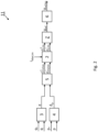
- Fig. 1 illustrates a control system 1 according to an exemplifying embodiment of the present disclosure.
- the control system 1 is configured to calculate a reference voltage vector u ref for a converter (not shown).
- the converter may be connected to a power grid at a point-of-common-coupling (PCC).
- PCC point-of-common-coupling
- the control system 1 may be configured to provide grid forming capabilities, by controlling the converter. Grid forming provided by the control system 1 may be seen as controlling the converter to emulate a voltage source connected to the PCC via an impedance Z, which may virtual or real.
- the control system 1 comprises an electromotive force, EMF-, limiter 2.
- the EMF-limiter may be configured to receive positive and negative sequence vectors e _ Unlim + , e _ Unlim ⁇ which have been decomposed of an EMF vector.
- the EMF-limiter 2 is configured to receive, and/or calculate, a predetermined current limit i MaxLim . Further, the EMF-limiter 2 is configured to monitor a vector i ABC,Unlim of reference currents for three phases to check (continuously or intermittently) whether any of the phases, i.e., components of the vector, exceed the predetermined current limit i MaxLim . If the predetermined current limit i MaxLim is exceeded, the EMF-limiter is configured to limit the positive and/or the negative sequence vectors of the EMF vector e _ Unlim + , e _ Unlim ⁇ .
- the vector i ABC,Unlim of reference currents may be a transformation of a positive and negative sequence vectors i _ Ref , Unlim + , i _ Ref , Unlim ⁇ of a reference current (not shown), which is shown in Fig. 1 as a transformation block 6.
- the transformation may be performed by other components of the control system 1.
- the EMF-limiter may be configured to receive, or calculate, the positive and negative sequence vectors i _ Ref , Unlim + , i _ Ref , Unlim ⁇ of the reference current, and then perform the transformation.
- the positive and negative sequence vectors i _ Ref , Unlim + , i _ Ref , Unlim ⁇ of the reference current may be calculated based on at least the following inputs: the positive and negative sequence vectors u + , u - of a PCC voltage vector (which is measured at the PCC), the EMF vector e _ Unlim + , e _ Unlim ⁇ , and the impedance Z + , Z - .
- the positive and negative sequence vectors i _ Ref , Unlim + , i _ Ref , Unlim ⁇ of the reference current is shown as being calculated by a component block 5 (discussed further in the below) having received the abovementioned inputs.
- the present disclosure is not limited to such a calculation, and that the positive and negative sequence vectors i _ Ref , Unlim + , i _ Ref , Unlim ⁇ of the reference current may be calculated by another component of the control system 1, such as the EMF-limiter 2, having received the abovementioned inputs.
- the vector i ABC,Unlim of reference currents for three phases is a transformation of the positive and negative sequence vectors i _ Ref , Unlim + , i _ Ref , Unlim ⁇ of the reference current, which is turn is determined based on the positive and the negative sequence vectors of the EMF vector e _ Unlim + , e _ Unlim ⁇ , a limitation of the positive and the negative sequence vectors of the EMF vector e _ Unlim + , e _ Unlim ⁇ thereby causes the vector i ABC,Unlim of reference currents for three phases to be limited.
- This limitation by the EMF-limiter 2 is performed until all components of the vector i ABC,Unlim of reference currents for three phases is below the predetermined current limit i MaxLim .
- the resulting output from the EMF-limiter 2, if the predetermined current limit i MaxLim is being exceeded, may be referenced to as the limited positive and negative sequence vectors of the EMF vector e _ Lim + , e _ Lim ⁇ .
- the control system 1 may further comprise a reactive power controller (RPC) 3 configured to calculate the EMF magnitude e of the (unlimited) EMF vector based on received signals of a reactive power reference q ⁇ and a reactive power q measured at the PCC.
- the control system 1 may further comprise an active power controller (APC) 4 configured to calculate an EMF angle ⁇ p of the (unlimited) EMF vector based on received signals of an active power reference p ⁇ and an active power p measured at the PCC.
- the RPC 3 and the APC 4 may be configured to calculate the components of the (unlimited) EMF vector for the rest of the control system 1.
- the RPC 3 and the APC 4 may further be configured to limit the EMF magnitude e and the EMF angle ⁇ p based on received maximum and minimum limits for the reactive power q max , q min , and the active power p max , p min .
- the EMF magnitude e and the EMF angle ⁇ p being output from the RPC 3 and the APC 4, respectively, are shown as being fed via another component 5 from which output is being fed to the EMF-limiter 2.
- the other component 5 may, for example, be understood as a general purpose calculation block of the control system 1.
- the component 5 may, alternatively or additionally, be understood as an active and reactive power limiter which may be configured to calculate the (unlimited) EMF vector and the reactive and/or the active power references p ⁇ , q ⁇ .
- the component 5 may further be configured to determine maximum and minimum limits for the EMF magnitude e and the EMF angle ⁇ p . Further, the limits for the EMF magnitude e and the EMF angle ⁇ p may be determined based on reactive power q max , q min limits, and active power limits p max , p min .
- the component 5, and/or the control system 1 may be configured to, continuously or intermittently, calculate limits of the EMF magnitude e and the EMF angle ⁇ p , which may be based on physical limitations of the converter and/or electrical characteristics at the PCC and or the limits for reactive power q max , q min , and the active power p max , p min .
- the active power limits p max , pmin and reactive power limits q max , q min may be received, by the component 5 and/or another component of the control system 1, or may be calculated, by the component 5 and/or another component of the control system 1, based on physical limitations of the converter and/or electrical characteristics at the PCC.
- the component 5 may be configured to calculate the positive and negative sequence vectors i _ Ref , Unlim + , i _ Ref , Unlim ⁇ and to transmit them to the EMF-limiter 2.
- the present disclosure is not limited to the component 5 calculating the positive and negative sequence vectors i _ Ref , Unlim + , i _ Ref , Unlim ⁇ , and the calculation may be performed by another portion of the control system 1, such as, for example, the EMF-limiter 2.
- Fig. 1 further shows the (potentially) limited positive and the negative sequence vectors of the EMF vector e _ Lim + , e _ Lim ⁇ being output from the EMF-limiter 2 and fed through an impedance block Z.
- the impedance block Z may alternatively be understood as an admittance block.
- the impedance block Z may be configured to receive the positive and the negative sequence vectors of the EMF vector e _ Lim + , e _ Lim ⁇ and the positive and negative sequence vectors of a PCC voltage vector, and to calculate the reference voltage vector u ref for the converter based on the received vectors, i.e. inputs.
- the calculation of the reference voltage vector u ref may further be based on positive and negative sequence vectors i + , i - of a PCC current vector (not shown).
- the control system 1 may be configured to receive the PCC current vector and to then decompose the PCC current vector into respective positive and negative sequence vectors.
- the impedance block Z is shown as receiving the positive and negative sequence vectors i + , i - of a PCC current vector, however, any component of the control system 1 may be configured to receive the PCC current vector and may be configured to decompose it, or it may be configured to receive the decomposed positive and negative sequence vectors i + , i - of a PCC current vector.
- the impedance block Z may be configured to calculate a reference current vector (not shown) in order to then calculate the reference voltage vector u ref .
- Fig. 2 illustrates a control system 11 according to an exemplifying embodiment of the present disclosure.
- Figs. 1 and 2 share a majority of their components. Therefore, reference is made to the text related to Fig. 1 in order to provide an increased understanding of the features which are shared by the exemplifying embodiments shown in Figs. 1 and 2 .
- control system 11 shown in Fig. 2 A difference between the control system 11 shown in Fig. 2 and the control system 1 shown in Fig. 1 is that the control system 11 shown in Fig. 2 further comprises a limiter block 6.
- the limiter block 6 may be configured to receive, or calculate, a maximum reference voltage limit, and may be configured to ensure that the reference voltage vector u ref does not exceed the maximum reference voltage limit. In other words, the limiter block 6 may be configured to limit the reference voltage vector u ref from exceeding the maximum reference voltage limit.
- the limiter block 6 may be configured to limit the reference voltage vector u ref output from the impedance block Z.
- the limiter block 6 may be configured to receive a reference current vector which has been calculated by the impedance block Z , and may then limit the reference current vector.
- the control system 11 may further comprise a current controller (not shown) configured to receive the (limited) reference current vector in order to calculate the (limited) reference voltage vector u ref .
- the reference voltage vector u ref would be limited by limiting the reference current vector.
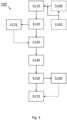
- Fig. 3 illustrates a flow chart of a method 100 according to an exemplifying embodiment of the present disclosure.
- the method 100 may include the step of receiving S110 a PCC voltage vector u g which is measured at a PCC, and an electromagnetic force, EMF, vector e unlim of the voltage source.
- the method may comprise, prior to the step of receiving S110, the step of calculating S105 the electromagnetic force, EMF, vector e of a voltage source based on active and reactive power references p ⁇ , q ⁇ and active and reactive power p, q, measured at the PCC wherein the method may further comprise calculating S106 the EMF magnitude e of the EMF vector e based on at least a reactive power reference q ⁇ and a reactive power q measured at the PCC, and the EMF angle ⁇ p of the EMF vector e based on at least an active power reference p ⁇ and an active power p measured at the PCC.
- the method 100 may further comprise the steps of decomposing S120 the PCC voltage vector, the EMF vector, and a vector representative of the impedance into, corresponding, positive and negative sequence vectors u + , u - , e +,unlim , e -,unlim , Z+, Z - , and calculating S130 positive and negative sequence vectors i _ Ref , Unlim + , i _ Ref , Unlim ⁇ of a reference current based on at least the positive and negative sequence vectors of the PCC voltage vector, the EMF vector, and the impedance.
- the method 100 may further comprise, while performing the steps of decomposing S120 and the calculating S130, limiting S125 the positive sequence EMF magnitude e + and the positive sequence EMF angle ⁇ p of the positive sequence EMF vector e + as well as the negative sequence EMF magnitude e - and the negative sequence EMF angle of the negative sequence EMF vector e - if the resulting power and/or the resulting reactive power falls outside of an active power range and a reactive power range, respectively.
- the method 100 may further comprise the step of transforming S140 the positive and negative sequence vectors of the reference current into a three-phase reference frame to obtain a vector i ABC,Unlim of reference currents for three phases.
- the method 100 further comprises the steps of determining S150 if one or more phase currents of the phase currents vector exceed a predetermined current limit i MaxLim , and if a determination S150 confirms that the predetermined current limit i MaxLim is exceeded, limiting S160 at least one of the positive and negative sequence vectors e +,lim , e -,lim , of the EMF vector such that the resulting one or more phase currents of the phase currents vector i ABC,Unlim is reduced below said predetermined current limit, and calculating S170 a reference voltage u ref based at least on the EMF vector output from the EMF-limiter.
Landscapes
- Engineering & Computer Science (AREA)
- Power Engineering (AREA)
- Supply And Distribution Of Alternating Current (AREA)
Abstract
Description
- The present disclosure relates to electric power systems, especially control of electric power systems.
- Synchronous generators provide power systems with important ancillary services, such as synchronizing and damping torque, high short-circuit currents and inertia. The ancillary services are important for being able to handle large disturbances in a power system, such as, for example, a short-circuit fault, and play a big part in why conventional synchronous generators are able to provide, so called, grid-forming capabilities.
- Power systems and power generation are going through a shift due to the increasing penetration of renewable energy sources, such as photovoltaic panels and wind turbines. In parallel with the increase of renewable energy sources, the integration of power-electronic systems, such as Flexible Alternating Current Transmission Systems (FACTS) and High-Voltage, Direct Current (HVDC) systems, has increased to deal with such renewable energy sources. Thereby, in order to properly meet the increase of renewable energy sources, there is a need for power-electronic systems being able to provide grid-forming capabilities, rather than so called grid-following capabilities.
- Therefore, there is a great interest in using converters, for example, of FACTS-and/or HVDC-systems, in a power system to more reliably provide grid-forming capabilities.
- It is therefore an object of the present invention to provide a control system, and a method thereof, which allows for using converters to provide grid-forming capabilities.
- According to a first aspect of the present disclosure, a control system is provided. The control system is provided for controlling a converter connected at a point-of-common-coupling (PCC) to emulate a voltage source connected to the PCC via an impedance. The system is configured to receive a PCC voltage vector which is measured at the PCC, and an electromagnetic force (EMF) vector of the voltage source. The system is further configured to decompose the PCC voltage vector, the EMF vector, and a vector representative of the impedance into, corresponding, positive and negative sequence vectors, and to calculate positive and negative sequence vectors of a reference current based on at least the positive and negative sequence vectors of the PCC voltage vector, the EMF vector, and the impedance. The system is further configured to transform the positive and negative sequence vectors of the reference current into a three-phase reference frame to obtain a vector of reference currents for three phases. The system comprises an EMF-limiter configured to, if one or more phase currents of the phase currents vector is determined to exceed a predetermined current limit, limit at least one of the positive and negative sequence vectors of the EMF vector such that the resulting one or more phase currents of the phase currents vector is reduced below said predetermined current limit. The system is configured to calculate a reference voltage vector based at least on the EMF vector output from the EMF-limiter.
- According to a second aspect of the present disclosure, a method is provided. The method is provided for controlling a converter connected at a PCC, to emulate a voltage source connected to the PCC via am impedance. The method comprises the steps of receiving a PCC voltage vector which is measured at the PCC, and an EMF vector of the voltage source, decomposing the PCC voltage vector, the EMF vector, and a vector representative of the impedance into, corresponding, positive and negative sequence vectors. The method comprises the steps of calculating positive and negative sequence vectors of a reference current based on at least the positive and negative sequence vectors of the PCC voltage vector, the EMF vector, and the impedance, and transforming the positive and negative sequence vectors of the reference current into a three-phase reference frame to obtain a vector of reference currents for three phases. The method further comprises the steps of determining if one or more phase currents of the phase currents vector exceed a predetermined current limit, and of so, limit at least one of the positive and negative sequence vectors of the EMF vector such that the resulting one or more phase currents of the phase currents vector is reduced below said predetermined current limit. The method further comprises calculating a reference voltage vector based at least on the EMF vector output from the EMF-limiter.
- The present disclosure is based on the concept of using positive and negative sequence vectors of the EMF vector in order to determine references for the converter such that physical limits of the converter are not exceeded. Further, the present disclosure provides for positive and negative sequence limitation, in order to preserve the grid forming capabilities of a converter. Thereby, an improved control of a converter connected to a power network at a PCC is provided. Further, the present disclosure may provide for an increased longevity of the converter and/or an increased level of security for people operating and/or maintaining the converter, or being near the converter, by ensuring that the physical limits of the converter are adhered to.
- Physical limits may include a maximum converter current and/or voltage of the converter. The converter may form part of a greater power system, which may consequently put additional limitations on the converter, such as, but not limited to, a maximum direct current (DC) a maximum DC voltage, and/or converter valve power limits. Such module limitations may be calculated, measure and/or determined by a module outside of the control system. The module may be communicatively coupled to the control system in order to be able to communicate the limitations. The module limitations may be aggregated to determine power limits, which may include maximum and/or minimum limits for active and/or reactive power. Further, the present disclosure may be configured to receive and/or calculate active and/or reactive power, which may be derived from a steady state model of the converter.
- The EMF vector of the voltage source may be calculated based on active and reactive power references and active and reactive power measured at the PCC.
- The control system and the method according to present disclosure may further comprise continuous evaluation of active and/or reactive power limits, and may be configured to limit, or bound, a magnitude and/or phase angle of the EMF vector based on said active and/or reactive power limits. Further, the active power range and the reactive power range may each be defined by a minimum limit and/or a maximum limit, respectively.
- The control system according to present disclosure may further comprise a power limiter configured for limiting the positive sequence EMF magnitude and/or the positive sequence EMF angle of the positive sequence EMF vector if the resulting active power falls outside of an active power range The power limiter may further be configured for limiting the negative sequence EMF magnitude and the negative sequence EMF angle of the negative sequence EMF vector if the resulting reactive power falls outside of a reactive power range. Consequently, the method according to the present disclosure may involve the corresponding step(s).
- The control system according to the present disclosure may further comprise a reactive power controller (RPC) configured to calculate the EMF magnitude of the EMF vector based on at least a reactive power reference and a reactive power measured at the PCC, and an active power controller (APC) configured to calculate the EMF angle of the EMF vector based on the active power reference and the active power measured at the PCC. The method according to the present disclosure may comprise the steps of calculating the EMF magnitude of the EMF vector based on at least a reactive power reference and a reactive power measured at the PCC and or calculating the EMF angle of the EMF vector based on the active power reference and the active power measured at the PCC.
- Further, the present disclosure may use conventional anti wind-up schemes, which may utilize a difference between unlimited and limited magnitude and/or phase angle of the EMF vector, so as to correct errors.
- The converter may be a modular multilevel converter (MMC). The converter may be connected to a power grid, such a national or regional power grid, at a PCC. The impedance may be a virtual impedance or a physical impedance.
- Decomposition of vectors into positive and/or negative sequence vectors may be made by conventional decomposition methods.
- The predetermined current limit may be calculated based on physical parameters of the converters and/or a power system to which the converter is connected. The physical parameters may include, but are not limited to, a measured thermal stress of semiconductors of the converter, thermal stress of a transformer of the converter, and/or a predetermined converter capability.
- Further, the present disclosure may include the use of a current reference limiter. The current reference limiter may be based on current refences measured after the virtual admittance, i.e., at the PCC. The current reference limiter may be configured to ensure that current references are below a maximum current limit. Thereby, the current reference limiter may protect the converter and/or the power system to which the converter is connected. However, the use of the current reference limiter may come at the cost of, temporarily, losing grid forming capabilities.
- The limiting of at least one of the EMF positive and negative sequence vectors, which may, alternatively, be referenced to in the following as "the EMF limiting", may be based on steady state peak values for output phases of the converter. The EMF limiting may then be configured to limit, bound, or bring down, peak output currents of the converter within limits. If possible, only the EMF magnitude may be limited. However, sometimes only limiting the EMF magnitude is not sufficient, and both the EMF magnitude and the EMF angle may have to be limited, or modified.
- The positive and negative sequence vectors of the reference current may be calculated according to the following equations:


- The reference current may also be understood as a predicted steady-state current, and the terms may be used interchangeably. In other words, the unlimited positive and negative sequence vectors of the steady-state current (or reference current) may be based on the corresponding positive and negative sequence vectors of the EMF vector minus the PCC voltage vector divided by the impedance vector. In other words, the predicted steady-state current vector may be determined based on a difference between the EMF vector and the PCC voltage vector.
- The limiting of at least one of the EMF positive and negative sequence vectors may be according to either of the following set of equations:


- The calculation of a maximum current limit may be made by parametrizing an affine curve where a maximum current lies and equating it to the maximum current limit. The affine curve could be parametrized as AA · e + BB = i, where


- To find the solution to the above parametrization of the affine curve, one can solve the following quadratic equation:

- The above quadratic equation can be transformed into a quadratic equation of the form Ax 2 + Bx + C = 0 with

- By taking the positive solution, the EMF magnitude can be found as:


- However, the above limitation may sometimes not be sufficient to ensure that all of the phase currents of the converter are below the predetermined current limit. In such a case, it may be necessary to apply further limitation by using a reduction factor, which may be defined by dividing the predetermined current limit with a calculated maximum phase current, i Max,ph, as follows:


- The maximum phase current may be extracted from the determined vector of reference currents for three phases, as follows:

- The above would lead to the following limitation of the positive and negative sequence vectors of the EMF vector:


- Further, the current reference limiter discussed in the above may use the reduction factor to reduce the current reference.
- The reference voltage may be determined by, at least, feeding the EMF vector through a, real or virtual, admittance or a, real or virtual, impedance or admittance. If a, real or virtual, impedance is used, a grid current measurement may further be used to determine the reference voltage. Thus, the reference voltage for the converter may be calculated based on the EMF vector output from the control system or method according to the present disclosure. The EMF vector, which may have been limited according to the present disclosure, may be input into a (virtual) admittance together with a voltage measured at the PCC to obtain a reference current. The reference current may be fed into a current controller in order to obtain the reference voltage. Alternatively, the EMF vector may be fed to a voltage controller, which may obtain the active and reactive powers measured at the PCC, wherein the voltage controller may be configured to determine the reference voltage. However, before feeding the EMF vector to the voltage controller, the present disclosure may include feeding the EMF vector through a virtual impedance, which may also have a current measured at the PCC as input signal, wherein the resulting output is fed to the voltage controller.
- It is noted that other embodiments using all possible combinations of features recited in the above-described embodiments, alternatives or examples, may be envisaged. Thus, the present disclosure also relates to all possible combinations of features mentioned herein.
- Exemplifying embodiments will now be described in more detail, with reference to the following appended drawings.
-
Figs. 1 to 2 illustrate control systems according to exemplifying embodiments of the present disclosure. -
Fig. 3 illustrates a flow chart according to an exemplifying embodiment of the present disclosure. - As illustrated in the figures, the sizes of elements and region may be exaggerated for illustrative purposes and, thus, are provided to illustrate the general structures of the embodiments. Like reference numerals refer to like elements throughout.
- Exemplifying embodiments will now be described more fully hereinafter with reference to the accompanying drawings in which currently preferred embodiments are shown. The invention may, however, be embodied in many different forms and should not be construed as limited to the embodiments set forth herein; rather, these embodiments are provided for thoroughness and completeness, and fully convey the scope of the invention to the skilled person.
-
Fig. 1 illustrates a control system 1 according to an exemplifying embodiment of the present disclosure. The control system 1 is configured to calculate a reference voltage vector u ref for a converter (not shown). The converter may be connected to a power grid at a point-of-common-coupling (PCC). The control system 1 may be configured to provide grid forming capabilities, by controlling the converter. Grid forming provided by the control system 1 may be seen as controlling the converter to emulate a voltage source connected to the PCC via an impedance Z, which may virtual or real. - The control system 1 comprises an electromotive force, EMF-,
limiter 2. The EMF-limiter may be configured to receive positive and negative sequence vectors

- The EMF-
limiter 2 is configured to receive, and/or calculate, a predetermined current limit iMaxLim. Further, the EMF-limiter 2 is configured to monitor a vector i ABC,Unlim of reference currents for three phases to check (continuously or intermittently) whether any of the phases, i.e., components of the vector, exceed the predetermined current limit iMaxLim. If the predetermined current limit iMaxLim is exceeded, the EMF-limiter is configured to limit the positive and/or the negative sequence vectors of the EMF vector
- The vector i ABC,Unlim of reference currents may be a transformation of a positive and negative sequence vectors

Fig. 1 as atransformation block 6. However, it is to be understood that the transformation may be performed by other components of the control system 1. For example, the EMF-limiter may be configured to receive, or calculate, the positive and negative sequence vectors
- The positive and negative sequence vectors
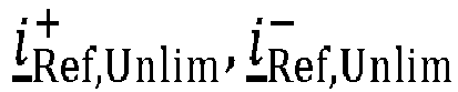

Fig.1 , the positive and negative sequence vectors

limiter 2, having received the abovementioned inputs. - Since the vector i ABC,Unlim of reference currents for three phases is a transformation of the positive and negative sequence vectors


limiter 2 is performed until all components of the vector i ABC,Unlim of reference currents for three phases is below the predetermined current limit iMaxLim. The resulting output from the EMF-limiter 2, if the predetermined current limit iMaxLim is being exceeded, may be referenced to as the limited positive and negative sequence vectors of the EMF vector
- The control system 1 may further comprise a reactive power controller (RPC) 3 configured to calculate the EMF magnitude e of the (unlimited) EMF vector based on received signals of a reactive power reference q∗ and a reactive power q measured at the PCC. The control system 1 may further comprise an active power controller (APC) 4 configured to calculate an EMF angle δp of the (unlimited) EMF vector based on received signals of an active power reference p∗ and an active power p measured at the PCC. Thereby, the
RPC 3 and theAPC 4 may be configured to calculate the components of the (unlimited) EMF vector for the rest of the control system 1. TheRPC 3 and theAPC 4 may further be configured to limit the EMF magnitude e and the EMF angle δp based on received maximum and minimum limits for the reactive power qmax, qmin, and the active power pmax, pmin. InFig. 1 , the EMF magnitude e and the EMF angle δp being output from theRPC 3 and theAPC 4, respectively, are shown as being fed via anothercomponent 5 from which output is being fed to the EMF-limiter 2. Theother component 5 may, for example, be understood as a general purpose calculation block of the control system 1. However, thecomponent 5 may, alternatively or additionally, be understood as an active and reactive power limiter which may be configured to calculate the (unlimited) EMF vector and the reactive and/or the active power references p∗, q∗. Thecomponent 5 may further be configured to determine maximum and minimum limits for the EMF magnitude e and the EMF angle δp . Further, the limits for the EMF magnitude e and the EMF angle δp may be determined based on reactive power qmax, qmin limits, and active power limits pmax, pmin. In other words, thecomponent 5, and/or the control system 1, may be configured to, continuously or intermittently, calculate limits of the EMF magnitude e and the EMF angle δp , which may be based on physical limitations of the converter and/or electrical characteristics at the PCC and or the limits for reactive power qmax, qmin, and the active power pmax, pmin. - The active power limits pmax, pmin and reactive power limits qmax, qmin may be received, by the
component 5 and/or another component of the control system 1, or may be calculated, by thecomponent 5 and/or another component of the control system 1, based on physical limitations of the converter and/or electrical characteristics at the PCC. - Further, the
component 5 may be configured to calculate the positive and negative sequence vectors
limiter 2. However, the present disclosure is not limited to thecomponent 5 calculating the positive and negative sequence vectors
limiter 2. -
Fig. 1 further shows the (potentially) limited positive and the negative sequence vectors of the EMF vector
limiter 2 and fed through an impedance block Z. The impedance block Z may alternatively be understood as an admittance block. The impedance block Z may be configured to receive the positive and the negative sequence vectors of the EMF vector
Fig. 1 the impedance block Z is shown as receiving the positive and negative sequence vectors i +,i - of a PCC current vector, however, any component of the control system 1 may be configured to receive the PCC current vector and may be configured to decompose it, or it may be configured to receive the decomposed positive and negative sequence vectors i +,i - of a PCC current vector. The impedance block Z may be configured to calculate a reference current vector (not shown) in order to then calculate the reference voltage vector u ref. -
Fig. 2 illustrates acontrol system 11 according to an exemplifying embodiment of the present disclosure. - The exemplifying embodiments shown in
Figs. 1 and2 share a majority of their components. Therefore, reference is made to the text related toFig. 1 in order to provide an increased understanding of the features which are shared by the exemplifying embodiments shown inFigs. 1 and2 . - A difference between the
control system 11 shown inFig. 2 and the control system 1 shown inFig. 1 is that thecontrol system 11 shown inFig. 2 further comprises alimiter block 6. - The
limiter block 6 may be configured to receive, or calculate, a maximum reference voltage limit, and may be configured to ensure that the reference voltage vector u ref does not exceed the maximum reference voltage limit. In other words, thelimiter block 6 may be configured to limit the reference voltage vector u ref from exceeding the maximum reference voltage limit. - The
limiter block 6 may be configured to limit the reference voltage vector u ref output from the impedance block Z. - Alternatively, the
limiter block 6 may be configured to receive a reference current vector which has been calculated by the impedance block Z, and may then limit the reference current vector. In such an alternative, thecontrol system 11 may further comprise a current controller (not shown) configured to receive the (limited) reference current vector in order to calculate the (limited) reference voltage vector u ref. Thereby, the reference voltage vector u ref would be limited by limiting the reference current vector. -
Fig. 3 illustrates a flow chart of amethod 100 according to an exemplifying embodiment of the present disclosure. - The
method 100 may include the step of receiving S110 a PCC voltage vector u g which is measured at a PCC, and an electromagnetic force, EMF, vector e unlim of the voltage source. - The method may comprise, prior to the step of receiving S110, the step of calculating S105 the electromagnetic force, EMF, vector e of a voltage source based on active and reactive power references p∗, q∗ and active and reactive power p, q, measured at the PCC wherein the method may further comprise calculating S106 the EMF magnitude e of the EMF vector e based on at least a reactive power reference q∗ and a reactive power q measured at the PCC, and the EMF angle δp of the EMF vector e based on at least an active power reference p∗ and an active power p measured at the PCC.
- The
method 100 may further comprise the steps of decomposing S120 the PCC voltage vector, the EMF vector, and a vector representative of the impedance into, corresponding, positive and negative sequence vectors u +, u -, e +,unlim, e -,unlim, Z+, Z -, and calculating S130 positive and negative sequence vectors
method 100 may further comprise, while performing the steps of decomposing S120 and the calculating S130, limiting S125 the positive sequence EMF magnitude e + and the positive sequence EMF angle δp of the positive sequence EMF vector e + as well as the negative sequence EMF magnitude e - and the negative sequence EMF angle of the negative sequence EMF vector e - if the resulting power and/or the resulting reactive power falls outside of an active power range and a reactive power range, respectively. - The
method 100 may further comprise the step of transforming S140 the positive and negative sequence vectors of the reference current into a three-phase reference frame to obtain a vector i ABC,Unlim of reference currents for three phases. - The
method 100 further comprises the steps of determining S150 if one or more phase currents of the phase currents vector exceed a predetermined current limiti MaxLim, and if a determination S150 confirms that the predetermined current limiti MaxLim is exceeded, limiting S160 at least one of the positive and negative sequence vectors e +,lim, e -,lim, of the EMF vector such that the resulting one or more phase currents of the phase currents vector i ABC,Unlim is reduced below said predetermined current limit, and calculating S170 a reference voltage u ref based at least on the EMF vector output from the EMF-limiter. - The invention has mainly been described above with reference to a few embodiments. However, as is readily appreciated by a person skilled in the art, other embodiments than the ones disclosed above are equally possible within the scope of the invention, as defined by the appended patent claims. Further, although features and elements are described above in particular combinations, each feature or element can be used alone without the other features and elements or in various combinations with or without other features and elements.
- Additionally, variations to the disclosed embodiments can be understood and effected by the skilled person in practicing the claimed invention, from a study of the drawings, the disclosure, and the appended claims. In the claims, the word "comprising" does not exclude other elements, and the indefinite article "a" or "an" does not exclude a plurality. The mere fact that certain features are recited in mutually different dependent claims does not indicate that a combination of these features cannot be used to advantage.
Claims (15)
- A control system (1) for controlling a converter connected at a point-of-common-coupling, PCC, to emulate a voltage source connected to the PCC via an impedance (Z), wherein the system is configured to:receive a PCC voltage vector which is measured at the PCC, and an electromagnetic force, EMF, vector (e unlim) of the voltage source; anddecompose the PCC voltage vector, the EMF vector, and a vector representative of the impedance into, corresponding, positive and negative sequence vectors (u+, u -,
 calculate positive and negative sequence vectors
 transform the positive and negative sequence vectors of the reference current into a three-phase reference frame to obtain a vector ( i ABC,Unlim) of reference currents for three phases;wherein the system comprises an EMF-limiter (2) configured to, if one or more phase currents of the phase currents vector ( i ABC,Unlim) is determined to exceed a predetermined current limit (i MaxLim), limit at least one of the positive and negative sequence vectors (e +,lim, e -,lim,) of the EMF vector such that the resulting one or more phase currents of the phase currents vector is reduced below said predetermined current limit; andwherein the system is configured to calculate a reference voltage vector (u ref) based at least on the EMF vector output from the EMF-limiter.
 - The control system according to claim 1, wherein the limiting of at least one of the EMF positive and negative sequence vectors (e +,unlim, e -,unlim,) is according to: or


- The control system according to claim 1 or 2, wherein the system is configured to calculate the electromagnetic force, EMF, vector (e unlim) of the voltage source based on active and reactive power references (p∗, q∗) and active and reactive power measured at the PCC (p, q).
- The control system according to claim 3, further comprising a power limiter configured for limiting the positive sequence EMF magnitude (e +) and the positive sequence EMF angle (δp ) of the positive sequence EMF vector ( e +) as well as the negative sequence EMF magnitude (e -) and the negative sequence EMF angle (δn ) of the negative sequence EMF vector ( e -) if the resulting power and/or the resulting reactive power falls outside of an active power range and a reactive power range, respectively.
- The control system according to claim 4, wherein the active power range and the reactive power range are each defined by a minimum limit (pmin, qmin) and/or a maximum limit (pmax, qmax), respectively.
- The control system according to any of the preceding claims, wherein the current positive and negative sequence vectors


- The control system according to any of claims 3 to 6, further comprisinga reactive power controller, RPC, (3) configured to calculate the EMF magnitude (e) of the EMF vector (e) based on at least a reactive power reference (q∗) and a reactive power (q) measured at the PCC; andan active power controller, APC, (4) configured to calculate the EMF angle (δp ) of the EMF vector (e) based on at least an active power reference (p∗) and an active power (p) measured at the PCC.
- The control system according to any of the preceding claims, wherein the reference voltage vector (u ref) is determined by at least:
feeding the positive and negative sequence vectors (e +,lim, e -,lim,) of the EMF vector output from the EMF-limiter (2) through the impedance (Z) or through a virtual admittance in order to obtain the calculated reference voltage vector (u ref). - A method (100) for controlling a converter connected at a point-of-common-coupling, PCC, to emulate a voltage source connected to the PCC via an impedance (Z), the method comprising the steps of:receiving (S110) a PCC voltage vector which is measured at the PCC, and an electromagnetic force, EMF, vector (e unlim) of the voltage source; anddecomposing (S120) the PCC voltage vector, the EMF vector, and a vector representative of the impedance into, corresponding, positive and negative sequence vectors (u +, u -, e +,unlim, e -,unlim, Z+, Z-);calculating (S130) positive and negative sequence vectors
 transforming (S140) the positive and negative sequence vectors of the reference current into a three-phase reference frame to obtain a vector ( i ABC,Unlim) of reference currents for three phases;determining (S150) if one or more phase currents of the phase currents vector exceed a predetermined current limit (i MaxLim), and if so, limit (S160) at least one of the positive and negative sequence vectors (e +,lim, e -,lim,) of the EMF vector such that the resulting one or more phase currents of the phase currents vector ( i ABC,Unlim) is reduced below said predetermined current limit; andcalculating (S170) a reference voltage (u ref) based at least on the EMF vector output from the EMF-limiter.
 - The method according to claim 9, wherein the step of limiting (S160) at least one of the EMF positive and negative sequence vectors (e +,unlim, e -,unlim,) is performed according to: or


- The method according to claim 9 or 10, further comprising the step of:
calculating (S105) the electromagnetic force, EMF, vector (e) of the voltage source based on active and reactive power references (p∗, q∗) and active and reactive power measured at the PCC (p, q). - The method according to claim 11, further comprising the step of:
limiting (S125) the positive sequence EMF magnitude (e +) and the positive sequence EMF angle (δp ) of the positive sequence EMF vector ( e +) as well as the negative sequence EMF magnitude (e -) and the negative sequence EMF angle (δn ) of the negative sequence EMF vector ( e -) if the resulting power and/or the resulting reactive power falls outside of an active power range and a reactive power range, respectively. - The method according to any of claims 9 to 12, the active power range and the reactive power range are each defined by a minimum limit (pmin, qmin) and/or a maximum limit (pmax, qmax), respectively.
- The method according to any of claims 9 to 13, wherein the positive and negative sequence vectors


- The method according to any of claims 9 to 14, further comprising the steps of:calculating (S106) the EMF magnitude (e) of the EMF vector (e) based on at least a reactive power reference (q∗) and a reactive power (q) measured at the PCC; andcalculating (S106) the EMF angle (δp ) of the EMF vector (e) based on at least an active power reference (p∗) and an active power (p) measured at the PCC.
Priority Applications (1)
| Application Number | Priority Date | Filing Date | Title |
|---|---|---|---|
| EP22200358.4A EP4350928A1 (en) | 2022-10-07 | 2022-10-07 | A control system configured for, and a method for, controlling a converter |
Applications Claiming Priority (1)
| Application Number | Priority Date | Filing Date | Title |
|---|---|---|---|
| EP22200358.4A EP4350928A1 (en) | 2022-10-07 | 2022-10-07 | A control system configured for, and a method for, controlling a converter |
Publications (1)
| Publication Number | Publication Date |
|---|---|
| EP4350928A1 true EP4350928A1 (en) | 2024-04-10 |
Family
ID=83689497
Family Applications (1)
| Application Number | Title | Priority Date | Filing Date |
|---|---|---|---|
| EP22200358.4A Pending EP4350928A1 (en) | 2022-10-07 | 2022-10-07 | A control system configured for, and a method for, controlling a converter |
Country Status (1)
| Country | Link |
|---|---|
| EP (1) | EP4350928A1 (en) |
-
2022
- 2022-10-07 EP EP22200358.4A patent/EP4350928A1/en active Pending
Non-Patent Citations (3)
| Title |
|---|
| ACHARYA SAMRAT ET AL: "A Control Strategy for Voltage Unbalance Mitigation in an Islanded Microgrid Considering Demand Side Management Capability", IEEE TRANSACTIONS ON SMART GRID, IEEE, USA, vol. 10, no. 3, 1 May 2019 (2019-05-01), pages 2558 - 2568, XP011720806, ISSN: 1949-3053, [retrieved on 20190419], DOI: 10.1109/TSG.2018.2804954 * |
| JAYANTI N G ET AL: "Sequence analysis based DSP controller for Dynamic Voltage Restorer (DVR)", POWER ELECTRONICS SPECIALISTS CONFERENCE, 2008. PESC 2008. IEEE, IEEE, PISCATAWAY, NJ, USA, 15 June 2008 (2008-06-15), pages 3986 - 3991, XP031300580, ISBN: 978-1-4244-1667-7 * |
| LI ZILIN ET AL: "An Adaptive Fault Ride-Through Scheme for Grid-Forming Inverters Under Asymmetrical Grid Faults", IEEE TRANSACTIONS ON INDUSTRIAL ELECTRONICS, IEEE SERVICE CENTER, PISCATAWAY, NJ, USA, vol. 69, no. 12, 20 December 2021 (2021-12-20), pages 12912 - 12923, XP011913993, ISSN: 0278-0046, [retrieved on 20211221], DOI: 10.1109/TIE.2021.3135641 * |
Similar Documents
| Publication | Publication Date | Title |
|---|---|---|
| US8593114B2 (en) | Control device for doubly-fed induction generator in which feedback linearization method is embedded | |
| EP2065994B1 (en) | Compensation of harmonics of electrical network | |
| EP2621046B1 (en) | System and method for reactive power regulation | |
| Marques et al. | Inner control method and frequency regulation of a DFIG connected to a DC link | |
| Park et al. | Reactive power P&O anti-islanding method for a grid-connected inverter with critical load | |
| US20160118877A1 (en) | Current source converter differential protection method and relay protection device | |
| US10027253B2 (en) | Voltage source converter | |
| US12095385B2 (en) | Power conversion device that calculates an estimated value of an upper impedance | |
| US9853582B2 (en) | Converter interconnected with a wind power generation farm to enable continuous power transmission and operating method thereof | |
| US10030632B2 (en) | Control device for voltage source converter and operating method thereof | |
| CN104782013A (en) | Wind power plant and method for supplying electrical energy | |
| KR101410744B1 (en) | Limitation method of the current and regeneration power reference using the grid-side converter capacity connected with utility grid | |
| Boukhriss et al. | Maximization of generated power from wind energy conversion systems using a doubly fed induction generator with active disturbance rejection control | |
| EP4050791B1 (en) | System and method for providing grid-forming control for a double-fed wind turbine generator | |
| EP3276771A1 (en) | Method and system for controlling voltage and frequency in an isolated network | |
| KR20150130865A (en) | Converter controller and operating method thereof | |
| US11942876B2 (en) | Power conversion device | |
| CN103296689A (en) | Method for compensation and handling of asymmetric sag of power grid based on negative-sequence current | |
| CN109193673B (en) | A grid adaptive detection platform voltage fluctuation and flicker control method | |
| Wang et al. | Comparison of Grid-Following and Grid-Forming Control in Weak AC System | |
| AU2021103722A4 (en) | A power flow control method for ac-dc hybrid power grid | |
| US20250070697A1 (en) | System and method for decoupling current command components in a synchronously-rotating frame | |
| Marques et al. | Control method of the DFIG connected to a DC link through a diode bridge | |
| CN110649636B (en) | Method and virtual synchronous generator control device for suppressing voltage oscillation of DC power system of multi-electric aircraft | |
| CN118117610A (en) | Control method of wind power generation system and wind power generation system |
Legal Events
| Date | Code | Title | Description |
|---|---|---|---|
| PUAI | Public reference made under article 153(3) epc to a published international application that has entered the european phase |
Free format text: ORIGINAL CODE: 0009012 |
|
| STAA | Information on the status of an ep patent application or granted ep patent |
Free format text: STATUS: THE APPLICATION HAS BEEN PUBLISHED |
|
| AK | Designated contracting states |
Kind code of ref document: A1 Designated state(s): AL AT BE BG CH CY CZ DE DK EE ES FI FR GB GR HR HU IE IS IT LI LT LU LV MC ME MK MT NL NO PL PT RO RS SE SI SK SM TR |
|
| STAA | Information on the status of an ep patent application or granted ep patent |
Free format text: STATUS: REQUEST FOR EXAMINATION WAS MADE |
|
| 17P | Request for examination filed |
Effective date: 20241007 |
|
| RBV | Designated contracting states (corrected) |
Designated state(s): AL AT BE BG CH CY CZ DE DK EE ES FI FR GB GR HR HU IE IS IT LI LT LU LV MC ME MK MT NL NO PL PT RO RS SE SI SK SM TR |