EP4350918A1 - Method and system for identifying dominant overvoltage of a high-proportion new energy power system, electronic device, storage medium, and computer program product - Google Patents
Method and system for identifying dominant overvoltage of a high-proportion new energy power system, electronic device, storage medium, and computer program product Download PDFInfo
- Publication number
- EP4350918A1 EP4350918A1 EP22939913.4A EP22939913A EP4350918A1 EP 4350918 A1 EP4350918 A1 EP 4350918A1 EP 22939913 A EP22939913 A EP 22939913A EP 4350918 A1 EP4350918 A1 EP 4350918A1
- Authority
- EP
- European Patent Office
- Prior art keywords
- new energy
- bus
- energy terminal
- voltage
- maximum
- Prior art date
- Legal status (The legal status is an assumption and is not a legal conclusion. Google has not performed a legal analysis and makes no representation as to the accuracy of the status listed.)
- Granted
Links
Images

Classifications
-
- H—ELECTRICITY
- H02—GENERATION; CONVERSION OR DISTRIBUTION OF ELECTRIC POWER
- H02J—ELECTRIC POWER NETWORKS; CIRCUIT ARRANGEMENTS OR SYSTEMS FOR SUPPLYING OR DISTRIBUTING ELECTRIC POWER; SYSTEMS FOR STORING ELECTRIC ENERGY
- H02J3/00—Circuit arrangements for AC mains or AC distribution networks
- H02J3/001—Arrangements for handling faults or abnormalities, e.g. emergencies or contingencies
- H02J3/0012—Arrangements for handling faults or abnormalities, e.g. emergencies or contingencies characterised by the contingency detection means in AC networks, e.g. using phasor measurement units [PMU], synchrophasors or contingency analysis
-
- H—ELECTRICITY
- H02—GENERATION; CONVERSION OR DISTRIBUTION OF ELECTRIC POWER
- H02H—EMERGENCY PROTECTIVE CIRCUIT ARRANGEMENTS
- H02H7/00—Emergency protective circuit arrangements specially adapted for specific types of electric machines or apparatus or for sectionalised protection of cable or line systems, and effecting automatic switching in the event of an undesired change from normal working conditions
- H02H7/22—Emergency protective circuit arrangements specially adapted for specific types of electric machines or apparatus or for sectionalised protection of cable or line systems, and effecting automatic switching in the event of an undesired change from normal working conditions for distribution gear, e.g. bus-bar systems; for switching devices
-
- G—PHYSICS
- G06—COMPUTING OR CALCULATING; COUNTING
- G06Q—INFORMATION AND COMMUNICATION TECHNOLOGY [ICT] SPECIALLY ADAPTED FOR ADMINISTRATIVE, COMMERCIAL, FINANCIAL, MANAGERIAL OR SUPERVISORY PURPOSES; SYSTEMS OR METHODS SPECIALLY ADAPTED FOR ADMINISTRATIVE, COMMERCIAL, FINANCIAL, MANAGERIAL OR SUPERVISORY PURPOSES, NOT OTHERWISE PROVIDED FOR
- G06Q10/00—Administration; Management
- G06Q10/06—Resources, workflows, human or project management; Enterprise or organisation planning; Enterprise or organisation modelling
- G06Q10/063—Operations research, analysis or management
- G06Q10/0635—Risk analysis of enterprise or organisation activities
-
- G—PHYSICS
- G06—COMPUTING OR CALCULATING; COUNTING
- G06Q—INFORMATION AND COMMUNICATION TECHNOLOGY [ICT] SPECIALLY ADAPTED FOR ADMINISTRATIVE, COMMERCIAL, FINANCIAL, MANAGERIAL OR SUPERVISORY PURPOSES; SYSTEMS OR METHODS SPECIALLY ADAPTED FOR ADMINISTRATIVE, COMMERCIAL, FINANCIAL, MANAGERIAL OR SUPERVISORY PURPOSES, NOT OTHERWISE PROVIDED FOR
- G06Q50/00—Information and communication technology [ICT] specially adapted for implementation of business processes of specific business sectors, e.g. utilities or tourism
- G06Q50/06—Energy or water supply
-
- H—ELECTRICITY
- H02—GENERATION; CONVERSION OR DISTRIBUTION OF ELECTRIC POWER
- H02H—EMERGENCY PROTECTIVE CIRCUIT ARRANGEMENTS
- H02H3/00—Emergency protective circuit arrangements for automatic disconnection directly responsive to an undesired change from normal electric working condition with or without subsequent reconnection ; integrated protection
- H02H3/20—Emergency protective circuit arrangements for automatic disconnection directly responsive to an undesired change from normal electric working condition with or without subsequent reconnection ; integrated protection responsive to excess voltage
-
- H—ELECTRICITY
- H02—GENERATION; CONVERSION OR DISTRIBUTION OF ELECTRIC POWER
- H02J—ELECTRIC POWER NETWORKS; CIRCUIT ARRANGEMENTS OR SYSTEMS FOR SUPPLYING OR DISTRIBUTING ELECTRIC POWER; SYSTEMS FOR STORING ELECTRIC ENERGY
- H02J3/00—Circuit arrangements for AC mains or AC distribution networks
- H02J3/001—Arrangements for handling faults or abnormalities, e.g. emergencies or contingencies
- H02J3/00125—Transmission line or load transient problems, e.g. overvoltage, resonance or self-excitation of inductive loads
Definitions
- the disclosure relates to, but is not limited to, the technical field of safety and stability analysis for a high-proportion new energy power system, and in particular to a method and system for identifying a dominant overvoltage of a high-proportion new energy power system, an electronic device, a storage medium, and a computer program product.
- Embodiments of the disclosure provides a method and system for identifying a dominant overvoltage of a high-proportion new energy power system, an electronic device, a storage medium, and a computer program product.
- a method for identifying a dominant overvoltage of a high-proportion new energy power system includes the following operations.
- a voltage amplitude of a new energy terminal and a voltage amplitude of an alternating-current (AC) bus at any moment after faults of the new energy terminal and the AC bus are cleared, are determined respectively.
- An overvoltage limit ratio is determined according to a ratio of the voltage amplitude of the new energy terminal to the voltage amplitude of the AC bus.
- a critical overvoltage limit ratio is determined.
- a maximum new energy terminal voltage value and a maximum AC bus voltage value bearable for the new energy terminal and the AC bus are determined respectively.
- Identification of a dominant voltage safety constraint is performed according to the overvoltage limit ratio, the critical overvoltage limit ratio, the maximum new energy terminal voltage value and the maximum AC bus voltage value, and an identification result is determined.
- a system for identifying a dominant overvoltage of a high-proportion new energy power system includes a voltage amplitude calculation unit, an overvoltage limit ratio determination unit, a critical overvoltage limit ratio determination unit, a maximum voltage value calculation unit and an identification unit.
- the voltage amplitude calculation unit is configured to determine a voltage amplitude of a new energy terminal and a voltage amplitude of an AC bus at any moment after faults of the new energy terminal and the AC bus are cleared respectively.
- the overvoltage limit ratio determination unit is configured to determine an overvoltage limit ratio according to a ratio of the voltage amplitude of the new energy terminal to the voltage amplitude of the AC bus.
- the critical overvoltage limit ratio determination unit is configured to determine a critical overvoltage limit ratio.
- the maximum voltage value calculation unit is configured to determine a maximum new energy terminal voltage value and a maximum AC bus voltage value bearable for the new energy terminal and the AC bus respectively.
- the identification unit is configured to perform identification of a dominant voltage safety constraint according to the overvoltage limit ratio, the critical overvoltage limit ratio, the maximum new energy terminal voltage value and the maximum AC bus voltage value, and determine an identification result.
- an embodiment of the disclosure provides a computer-readable storage medium, having stored thereon a computer program, the program implements operations of the method for identifying a dominant overvoltage of a high-proportion new energy power system when the program is executed by a processor.
- an embodiment of the disclosure provides an electronic device, the electronic device includes the above computer-readable storage medium and one or more processors configured to execute the program in the computer-readable storage medium.
- an embodiment of the disclosure provides a computer program product, the computer program product includes a computer instruction, the computer instruction enables a computer device to perform operations of the above method for identifying a dominant overvoltage of a high-proportion new energy power system when the computer instruction is executed on the computer device.
- the embodiments of the disclosure provide a method and system for identifying a dominant overvoltage of a high-proportion new energy power system, including the following operations.
- An overvoltage limit ratio is determined according to a ratio of the voltage amplitude of the new energy terminal to the voltage amplitude of the AC bus.
- a critical overvoltage limit ratio is determined.
- a maximum new energy terminal voltage value and a maximum AC bus voltage value bearable for the new energy terminal and the AC bus are determined respectively.
- Identification of a dominant voltage safety constraint is performed according to the overvoltage limit ratio, the critical overvoltage limit ratio, the maximum new energy terminal voltage value and the maximum AC bus voltage value, and an identification result is determined.
- the embodiments of the disclosure take a voltage source converter (VSC) grid-connected system as a research object, establish a voltage analytical calculation model which considers dynamic characteristics of a PLL, and reveal a correlation relationship between voltage dynamics of the VSC grid-connected system and dynamics of the PLL; and take an overvoltage limit ratio as an index, and implement identification of a dominant voltage constraint by considering an overvoltage limit.
- VSC voltage source converter
- the embodiments of the disclosure may provide strong support for safety and stability analysis and control of the high-proportion new energy power system.
- FIG. 1 is a flowchart of a method 100 for identifying a dominant overvoltage of a high-proportion new energy power system according to an embodiment of the disclosure.
- the method for identifying a dominant overvoltage of a high-proportion new energy power system takes a voltage source converter (VSC) grid-connected system as a research object, establishes a voltage analytical calculation model which considers dynamic characteristics of a phase locked loop (PLL), and reveals a correlation relationship between voltage dynamics of the VSC grid-connected system and dynamics of the PLL; and takes an overvoltage limit ratio as an index, and implements identification of a dominant voltage constraint by considering an overvoltage limit.
- VSC voltage source converter
- PLL phase locked loop
- the embodiments of the disclosure may provide strong support for safety and stability analysis and control of the high-proportion new energy power system.
- the method 100 for identifying a dominant overvoltage of a high-proportion new energy power system provided by the embodiment of the disclosure starts from operation 101.
- a voltage amplitude of a new energy terminal and a voltage amplitude of an alternating-current (AC) bus at any moment after faults of the new energy terminal and the AC bus are cleared, are determined respectively.
- AC alternating-current
- U t ) is a voltage amplitude of the new energy terminal at a moment t
- u f q t is a q-axis component of a voltage of the new energy terminal at the moment t;
- VSC is a commonly used grid-connected interface of a new energy power generation device.
- the embodiment of the disclosure establishes a VSC grid-connected system model which considers dynamics of the PLL, as shown in FIG. 2 .
- u r , u s and u g are a voltage of the new energy terminal, a voltage of the AC bus and an electromotive force of an equivalent power supply of an AC power grid, respectively;
- L c , L r and L g are an equivalent inductance of a filter, a grid-connected inductance and an equivalent inductance of a receiving end grid, respectively.
- VSC adopts a grid voltage orientation based on the PLL.
- a "dot" added above a letter represents calculation of a derivative of a variable represented by the letter with respect to time, for example, x represents calculation of a derivative of x with respect to time.
- a control strategy for overvoltage occurred to the VSC grid-connected system is analyzed.
- Uncoordinated control of a new energy generation device with a characteristic of reactive power control in a large disturbance transient process is a main cause of overvoltage occurred to the VSC grid-connected system.
- the embodiment of the disclosure is based on state switching of a VSC control outer loop at a grid side of the new energy power generation device, and divides the large disturbance transient process into four stages, as shown in FIG. 4 .
- Stage I a stable operation state ( t ⁇ t 1 ).
- Stage II a low voltage crossing state ( t 1 ⁇ t ⁇ t 2 ).
- a large disturbance fault occurs to the VSC grid-connected system at a moment t 1 , which causes voltage at a grid-connected point dropping rapidly, and the VSC grid-connected system enters the low voltage crossing state due to a too low voltage caused by dropping, until the large disturbance fault is cleared at a moment t 2 , here a dropping degree of the voltage of the new energy terminal is related to factors such as a fault type, a fault degree, etc.
- the electromotive force of the equivalent power supply of the AC power grid U g 0.1 p.u., and the control outer loop is in a cut-out state.
- Stage III an initial stage after the fault is cleared ( t 2 ⁇ t ⁇ t 3 ).
- the VSC grid-connected system enters a fault recovery stage at a moment t 2 , and due to impacts of voltage measurement, feedback and other links, the control outer loop of the new energy power generation device may be delayed by about 20 ms to put-in again, that is, at a moment t 3 .
- the electromotive force of the equivalent power supply of the AC power grid U g 1.0 p.u.
- the control outer loop is in a cut-out state.
- the active power P r and reactive power Q r injected by VSC into the power system are 0 p.u. and 1.0 p.u., respectively.
- Stage IV restoring to the stable operation state ( t > t 3 ).
- the VSC grid-connected system After the large disturbance fault occurs to the system, the VSC grid-connected system generates overvoltage due to short-time reactive power surplus in stage III.
- U, ( t ) is a voltage amplitude of the new energy terminal at a moment t
- u f q t is a q-axis component of a voltage of the new energy terminal at the moment t
- u r d t is a d-axis component of the voltage of the new energy terminal at the moment t
- U g is an electromotive force of an equivalent power supply of an AC power grid
- ⁇ pll ( t ) is an angular frequency of a PLL at the moment t
- ⁇ pll ( t ) is a phase locked angle of the PLL at the
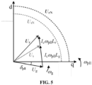
- FIG. 5 shows a relationship between main electrical quantities in the VSC grid-connected system, and dynamic processes of the voltage U r of the new energy terminal and the voltage U s of the AC bus are similar in a transient process.
- an outermost arc is the voltage amplitude U r of the new energy terminal
- an inner arc is the voltage amplitude U s of the AC bus.
- an overvoltage limit ratio is determined according to a ratio of the voltage amplitude of the new energy terminal to the voltage amplitude of the AC bus.
- the overvoltage limit ratio is determined according to the voltage amplitude of the new energy terminal to the voltage amplitude of the AC bus, to determine a device and AC bus to which voltage-exceeding-limit firstly occurs, of the VSC grid-connected system, that is, to determine the dominant voltage safety constraint.
- the embodiment of the disclosure defines the ratio of the voltage amplitude U r of the new energy terminal to the voltage amplitude U s of the AC bus as the overvoltage limit ratio N.
- a critical overvoltage limit ratio is determined.
- the device and bus to which overvoltage-exceeding-limit occurs, of the power system are related to the overvoltage limit ratio N.
- N m 1 + L r L g ⁇ L r U g 2 L g ⁇ ⁇ g 2 L r 2 + L r L g 1 U sN 2
- N m is the critical overvoltage limit ratio
- L v is an equivalent reactance between the new energy terminal and the AC bus
- U g is an electromotive force of an equivalent power supply of an AC power grid
- ⁇ g is an angular frequency of the AC power grid
- L g is an equivalent reactance from the AC bus to an infinite power supply
- U sN is a preset overvoltage limit value of the AC bus.
- a maximum new energy terminal voltage value and a maximum AC bus voltage value bearable for the new energy terminal and the AC bus are determined respectively.
- identification of a dominant voltage safety constraint is performed according to the overvoltage limit ratio, the critical overvoltage limit ratio, the maximum new energy terminal voltage value and the maximum AC bus voltage value, and an identification result is determined.
- the operation of performing identification of the dominant voltage safety constraint according to the overvoltage limit ratio, the critical overvoltage limit ratio, the maximum new energy terminal voltage value and the maximum AC bus voltage value, and determining the identification result includes the following operations.
- the voltage-exceeding-limit firstly occurs to the new energy terminal, in response to that the voltage amplitude of the new energy terminal is less than or equal to the maximum new energy terminal voltage value, and the overvoltage limit ratio is greater than 1 and less than the critical overvoltage limit ratio.
- the voltage-exceeding-limit simultaneously occurs to the new energy terminal and the AC bus, in response to that the voltage amplitude of the new energy terminal is less than or equal to the maximum new energy terminal voltage value, and the overvoltage limit ratio is equal to the critical overvoltage limit ratio.
- the voltage-exceeding-limit firstly occurs to the AC bus, in response to that the voltage amplitude of the AC bus is less than or equal to the maximum AC bus voltage value, and the overvoltage limit ratio is greater than the critical overvoltage limit ratio.
- the dominant voltage safety constraint of the high-proportion new energy power system is identified based on the overvoltage limit ratio N.
- the following type 1, type 2, type 3 and type 4 are included.
- Type 1 when U r ⁇ U r_max and N ⁇ 1, in this type, the voltage amplitude U r of the new energy terminal is less than or equal to the voltage amplitude U s of the AC bus. It may be known from the vector relationship between electrical quantities in FIG. 5 that the voltage-exceeding-limit firstly occurs to the new energy terminal, and is constrained by an overvoltage protection setting value U rN of the new energy terminal.
- Type 2 when U r ⁇ U r_max and 1 ⁇ N ⁇ N m , it may be known from the above descriptions that a protection action triggered by overvoltage under this configuration strategy firstly occurs to the new energy terminal and is constrained by the voltage amplitude U r of the new energy terminal.
- Type 4 when U s ⁇ U s_max and N > N m , a protection action triggered by overvoltage under this configuration strategy firstly occurs to the AC bus and is constrained by the voltage amplitude U s of the AC bus.
- the embodiment of the disclosure focuses on an overvoltage problem caused after clearing the large disturbance fault of the high-proportion new energy power system.
- the embodiment of the disclosure takes a VSC grid-connected system as a research object, establishes a voltage analytical calculation model which considers dynamic characteristics of a PLL, and reveals a correlation relationship between voltage dynamics of the VSC grid-connected system and dynamics of the PLL; and proposes an overvoltage limit ratio as an index, and implements identification of a dominant overvoltage constraint by considering an overvoltage limit.
- Relevant research results may provide strong support for safety and stability analysis and control of the high-proportion new energy power system.
- Operation 1 a correlation relationship between voltage dynamics of the VSC grid-connected system and dynamics of the PLL is analyzed, and an analytical expression which may characterize the correlation relationship is established.
- Operation 2 a control strategy of the VSC grid-connected system during a large disturbance transient is analyzed, and a stage where overvoltage occurs is identified.
- Operation 3 a coupling relationship among overvoltage of different devices and buses of the high-proportion new energy power system is analyzed, and an analytical expression between voltage dynamics and dynamics of the PLL in the overvoltage stage is established.
- an overvoltage limit ratio is calculated, and a dominant overvoltage constraint of the high-proportion new energy power system is determined based on the overvoltage limit ratio.
- U I is a highest operation voltage at a voltage level of the AC bus;
- U g is a reference voltage; and
- k s is an overvoltage capability coefficient.
- an overvoltage limit ratio N 0.955 under this overvoltage protection configuration strategy. It may be known from Table 1 that the new energy terminal firstly reaches its overvoltage protection setting value, which triggers a rapid terminal tripping action, and a dominant voltage safety constraint is a voltage of the new energy terminal.
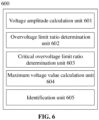
- FIG. 6 is a schematic structural diagram of a system 600 for identifying a dominant overvoltage of a high-proportion new energy power system according to an embodiment of the disclosure.
- the system 600 for identifying a dominant overvoltage of a high-proportion new energy power system provided by the embodiment of the disclosure includes a voltage amplitude calculation unit 601, an overvoltage limit ratio determination unit 602, a critical overvoltage limit ratio determination unit 603, a maximum voltage value calculation unit 604 and an identification unit 605.
- the voltage amplitude calculation unit 601 is configured to determine a voltage amplitude of a new energy terminal and a voltage amplitude of an AC bus at any moment after faults of the new energy terminal and the AC bus are cleared respectively.
- the voltage amplitude calculation unit 601 is specifically configured to determine the voltage amplitude of the new energy terminal and the voltage amplitude of the AC bus at any moment after faults of the new energy terminal and the AC bus are cleared respectively according to the following formulas (14) and (15):
- U r ( t ) is a voltage amplitude of the new energy terminal at a moment t
- u f q t is a q-axis component of a voltage of the
- the overvoltage limit ratio determination unit 602 is configured to determine an overvoltage limit ratio according to a ratio of the voltage amplitude of the new energy terminal to the voltage amplitude of the AC bus.
- the critical overvoltage limit ratio determination unit 603 is configured to determine a critical overvoltage limit ratio.
- the maximum voltage value calculation unit 604 is configured to determine a maximum new energy terminal voltage value and a maximum AC bus voltage value bearable for the new energy terminal and the AC bus respectively.
- the maximum voltage value calculation unit 604 is specifically configured to determine the maximum new energy terminal voltage value and the maximum AC bus voltage value bearable for the new energy terminal and the AC bus respectively according to the following formulas (17) and (18):
- U r _ max U g 2 + 2 U g ⁇ g L ⁇ + ⁇ g L ⁇ 2
- U s _ max U g 2 + 2 U g ⁇ g L g + ⁇ g L g 2
- U r_max is the maximum new energy terminal voltage value
- U s_max is the maximum AC bus voltage value
- U g is an electromotive force of an equivalent power supply of an AC power grid
- ⁇ g is an angular frequency of the AC power grid
- L ⁇ is an equivalent reactance from the new energy terminal to an infinite power supply
- L p is an equivalent reactance from the AC bus to the infinite power supply.
- the identification unit 605 is configured to perform identification of a dominant voltage safety constraint according to the overvoltage limit ratio, the critical overvoltage limit ratio, the maximum new energy terminal voltage value and the maximum AC bus voltage value, and determine an identification result.
- the identification unit 605 configured to perform identification of the dominant voltage safety constraint according to the overvoltage limit ratio, the critical overvoltage limit ratio, the maximum new energy terminal voltage value and the maximum AC bus voltage value, and determine the identification result, includes that the identification unit is configured to:
- the system 600 for identifying a dominant overvoltage of a high-proportion new energy power system according to the embodiment of the disclosure corresponds to the method 100 for identifying a dominant overvoltage of a high-proportion new energy power system according to another embodiment of the disclosure, and will not be elaborated here.
- an embodiment of the disclosure provides a computer-readable storage medium, having stored thereon a computer program, the program implements any one of operations of the method for identifying a dominant overvoltage of a high-proportion new energy power system when the program is executed by a processor.
- an embodiment of the disclosure provides an electronic device, the electronic device includes the above computer-readable storage medium and one or more processors configured to execute the program in the computer-readable storage medium.
- an embodiment of the disclosure provides a computer program product, the computer program product includes a computer instruction, the computer instruction enables a computer device to perform operations of the above method for identifying a dominant overvoltage of a high-proportion new energy power system when the computer instruction is executed on the computer device.
- the embodiments of the disclosure may be provided as methods, systems or computer program products. Therefore, the disclosure may take forms of embodiments with entire hardware, embodiments with entire software, or embodiments combining software with hardware aspects. Furthermore, the disclosure may take a form of a computer program product implemented on one or more computer-available storage media (including, but not limited to a disk storage, a Compact Disk Read Only Memory (CD-ROM), an optical storage, etc.) containing computer-available program codes.
- CD-ROM Compact Disk Read Only Memory
- These computer program instructions may also be stored in a computer-readable memory which may guide a computer or another programmable data processing device to operate in a specific manner, such that the instructions stored in the computer-readable memory generate a manufactured product including an instruction device, and the instruction device implements functions specified in one or more flows of the flowcharts and/or one or more blocks of the block diagrams.
- These computer program instructions may also be loaded onto a computer or another programmable data processing device, such that a series of operations are executed on the computer or another programmable device to generate computer-implemented processing, and thus the instructions executed on the computer or another programmable device provide operations for implementing functions specified in one or more flows of the flowcharts and/or one or more blocks of the block diagrams.
Landscapes
- Business, Economics & Management (AREA)
- Engineering & Computer Science (AREA)
- Human Resources & Organizations (AREA)
- Economics (AREA)
- Strategic Management (AREA)
- Tourism & Hospitality (AREA)
- General Business, Economics & Management (AREA)
- Power Engineering (AREA)
- Health & Medical Sciences (AREA)
- Marketing (AREA)
- Theoretical Computer Science (AREA)
- Entrepreneurship & Innovation (AREA)
- General Physics & Mathematics (AREA)
- Physics & Mathematics (AREA)
- Quality & Reliability (AREA)
- Development Economics (AREA)
- Operations Research (AREA)
- Educational Administration (AREA)
- Public Health (AREA)
- Water Supply & Treatment (AREA)
- General Health & Medical Sciences (AREA)
- Primary Health Care (AREA)
- Game Theory and Decision Science (AREA)
- Supply And Distribution Of Alternating Current (AREA)
- Measurement Of Current Or Voltage (AREA)
- Power Sources (AREA)
Abstract
Description
- This application is filed based on and claims priority to
Chinese Patent application No. 202210475787.1 filed on April 29, 2022 - The disclosure relates to, but is not limited to, the technical field of safety and stability analysis for a high-proportion new energy power system, and in particular to a method and system for identifying a dominant overvoltage of a high-proportion new energy power system, an electronic device, a storage medium, and a computer program product.
- With the increasing proportion of power electronic devices such as new energy power generation devices or the like in installed capacity of a power system, safety and stability characteristics of the power system are undergoing significant changes. Safety issues of new power systems, represented by overvoltage, have become increasingly prominent, which greatly restricts access scales of the new energy power generation devices in the power system.
- In a high-proportion new energy power system, there are numerous causation and rich function mechanisms to induce overvoltage, and there are obvious differences in possibility of overvoltage occurred to different devices and buses in a power grid and risks caused by the overvoltage. Therefore, it is of great practical significance to analyze risks and their correlation relationships of overvoltage of different devices and buses, locate a dominant overvoltage constraint and further take corresponding suppression and protection measures, to guide design of controllers in the new energy power generation devices and safety and guide stability analysis and control of the high-proportion new energy power system.
- However, existing researches mainly focus on calculation and evaluation of degree of overvoltage of the power system, with little focus on analysis and research of correlation relationships of overvoltage among different devices and buses in the power grid, and especially, research on a method for identifying a dominant overvoltage by considering an overvoltage limit has not been reported yet. In a word, a method for identifying a dominant overvoltage of a high-proportion new energy power system by considering dynamics of a phase locked loop (PLL), is still absent at present.
- Embodiments of the disclosure provides a method and system for identifying a dominant overvoltage of a high-proportion new energy power system, an electronic device, a storage medium, and a computer program product.
- According to an aspect of the embodiments of the disclosure, there is provided a method for identifying a dominant overvoltage of a high-proportion new energy power system, the method includes the following operations.
- A voltage amplitude of a new energy terminal and a voltage amplitude of an alternating-current (AC) bus at any moment after faults of the new energy terminal and the AC bus are cleared, are determined respectively.
- An overvoltage limit ratio is determined according to a ratio of the voltage amplitude of the new energy terminal to the voltage amplitude of the AC bus.
- A critical overvoltage limit ratio is determined.
- A maximum new energy terminal voltage value and a maximum AC bus voltage value bearable for the new energy terminal and the AC bus are determined respectively.
- Identification of a dominant voltage safety constraint is performed according to the overvoltage limit ratio, the critical overvoltage limit ratio, the maximum new energy terminal voltage value and the maximum AC bus voltage value, and an identification result is determined.
- According to another aspect of the embodiments of the disclosure, there is provided a system for identifying a dominant overvoltage of a high-proportion new energy power system, the system includes a voltage amplitude calculation unit, an overvoltage limit ratio determination unit, a critical overvoltage limit ratio determination unit, a maximum voltage value calculation unit and an identification unit.
- The voltage amplitude calculation unit is configured to determine a voltage amplitude of a new energy terminal and a voltage amplitude of an AC bus at any moment after faults of the new energy terminal and the AC bus are cleared respectively.
- The overvoltage limit ratio determination unit is configured to determine an overvoltage limit ratio according to a ratio of the voltage amplitude of the new energy terminal to the voltage amplitude of the AC bus.
- The critical overvoltage limit ratio determination unit is configured to determine a critical overvoltage limit ratio.
- The maximum voltage value calculation unit is configured to determine a maximum new energy terminal voltage value and a maximum AC bus voltage value bearable for the new energy terminal and the AC bus respectively.
- The identification unit is configured to perform identification of a dominant voltage safety constraint according to the overvoltage limit ratio, the critical overvoltage limit ratio, the maximum new energy terminal voltage value and the maximum AC bus voltage value, and determine an identification result.
- According to another aspect of the embodiments of the disclosure, an embodiment of the disclosure provides a computer-readable storage medium, having stored thereon a computer program, the program implements operations of the method for identifying a dominant overvoltage of a high-proportion new energy power system when the program is executed by a processor.
- According to another aspect of the embodiments of the disclosure, an embodiment of the disclosure provides an electronic device, the electronic device includes the above computer-readable storage medium and one or more processors configured to execute the program in the computer-readable storage medium.
- According to another aspect of the embodiments of the disclosure, an embodiment of the disclosure provides a computer program product, the computer program product includes a computer instruction, the computer instruction enables a computer device to perform operations of the above method for identifying a dominant overvoltage of a high-proportion new energy power system when the computer instruction is executed on the computer device.
- The embodiments of the disclosure provide a method and system for identifying a dominant overvoltage of a high-proportion new energy power system, including the following operations. A voltage amplitude of a new energy terminal and a voltage amplitude of an AC bus at any moment after faults of the new energy terminal and the AC bus are cleared, are determined respectively. An overvoltage limit ratio is determined according to a ratio of the voltage amplitude of the new energy terminal to the voltage amplitude of the AC bus. A critical overvoltage limit ratio is determined. A maximum new energy terminal voltage value and a maximum AC bus voltage value bearable for the new energy terminal and the AC bus are determined respectively. Identification of a dominant voltage safety constraint is performed according to the overvoltage limit ratio, the critical overvoltage limit ratio, the maximum new energy terminal voltage value and the maximum AC bus voltage value, and an identification result is determined. The embodiments of the disclosure take a voltage source converter (VSC) grid-connected system as a research object, establish a voltage analytical calculation model which considers dynamic characteristics of a PLL, and reveal a correlation relationship between voltage dynamics of the VSC grid-connected system and dynamics of the PLL; and take an overvoltage limit ratio as an index, and implement identification of a dominant voltage constraint by considering an overvoltage limit. The embodiments of the disclosure may provide strong support for safety and stability analysis and control of the high-proportion new energy power system.
- Exemplary embodiments of the disclosure may be understood more completely with reference to the following drawings.
-
FIG. 1 is a flowchart of amethod 100 for identifying a dominant overvoltage of a high-proportion new energy power system according to an embodiment of the disclosure. -
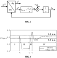
FIG. 2 is a schematic diagram of a model of a VSC grid-connected system which considers dynamics of a PLL according to an embodiment of the disclosure. -
FIG. 3 is a topology diagram of a control link of a PLL according to an embodiment of the disclosure. -
FIG. 4 is a schematic diagram of a voltage variation of a VSC grid-connected system in a large disturbance transient process according to an embodiment of the disclosure. -
FIG. 5 is a schematic diagram of an electrical vector relationship according to an embodiment of the disclosure. -
FIG. 6 is a schematic structural diagram of asystem 600 for identifying a dominant overvoltage of a high-proportion new energy power system according to an embodiment of the disclosure. - Exemplary embodiments of the disclosure are described now with reference to the drawings. However, the disclosure may be implemented in many different forms and is not limited to the embodiments described here. These embodiments are provided to disclose the disclosure thoroughly and completely, and to fully convey the scope of the disclosure to those skilled in the art. Terms of the exemplary embodiments represented in the drawings are not intended to limit the disclosure. In the drawings, the same unit/component is marked with the same reference symbol.
- Unless otherwise specified, terms used here (including technological terms) have commonly understood meanings to those skilled in the art. Furthermore, it may be understood that terms defined in commonly used dictionaries should be understood to have meanings consistent with the context of their relevant field, and should not be understood as idealistic or too formal meanings.
-
FIG. 1 is a flowchart of amethod 100 for identifying a dominant overvoltage of a high-proportion new energy power system according to an embodiment of the disclosure. As shown inFIG. 1 , the method for identifying a dominant overvoltage of a high-proportion new energy power system provided by the embodiment of the disclosure takes a voltage source converter (VSC) grid-connected system as a research object, establishes a voltage analytical calculation model which considers dynamic characteristics of a phase locked loop (PLL), and reveals a correlation relationship between voltage dynamics of the VSC grid-connected system and dynamics of the PLL; and takes an overvoltage limit ratio as an index, and implements identification of a dominant voltage constraint by considering an overvoltage limit. The embodiments of the disclosure may provide strong support for safety and stability analysis and control of the high-proportion new energy power system. Themethod 100 for identifying a dominant overvoltage of a high-proportion new energy power system provided by the embodiment of the disclosure starts fromoperation 101. At 101, a voltage amplitude of a new energy terminal and a voltage amplitude of an alternating-current (AC) bus at any moment after faults of the new energy terminal and the AC bus are cleared, are determined respectively. - Preferably, the operation of determining the voltage amplitude of the new energy terminal and the voltage amplitude of the AC bus at any moment after faults of the new energy terminal and the AC bus are cleared respectively, includes the following formulas:


here U, (t) is a voltage amplitude of the new energy terminal at a moment t;


- VSC is a commonly used grid-connected interface of a new energy power generation device. The embodiment of the disclosure establishes a VSC grid-connected system model which considers dynamics of the PLL, as shown in
FIG. 2 . A voltage equation thereof is:
here i c is an input current; ur , us and ug are a voltage of the new energy terminal, a voltage of the AC bus and an electromotive force of an equivalent power supply of an AC power grid, respectively; and L c, L r and L g are an equivalent inductance of a filter, a grid-connected inductance and an equivalent inductance of a receiving end grid, respectively. - VSC adopts a grid voltage orientation based on the PLL. A topology diagram of a control link of the PLL is shown in
FIG. 3 , and a control system equation thereof is:
here θ pll is a phase-locked angle of the PLL, k p_pll and k i_pll are PI parameters of the PLL,
- In the embodiment of the disclosure, a control strategy for overvoltage occurred to the VSC grid-connected system is analyzed.
- Uncoordinated control of a new energy generation device with a characteristic of reactive power control in a large disturbance transient process is a main cause of overvoltage occurred to the VSC grid-connected system. The embodiment of the disclosure is based on state switching of a VSC control outer loop at a grid side of the new energy power generation device, and divides the large disturbance transient process into four stages, as shown in
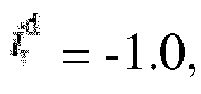
FIG. 4 . - Stage I: a stable operation state (t<t 1). At this stage, the VSC grid-connected system operates in a rated state, the electromotive force of the equivalent power supply of the AC power grid Ug = 1.0 p.u., and the control outer loop is in a put-in state. Under the stable operation state, an active power P r and reactive power Q r injected by VSC into a power system are 1.0 p.u. and 0 respectively. Therefore, there are the following assumptions:

- Stage II: a low voltage crossing state (t 1<t<t 2). A large disturbance fault occurs to the VSC grid-connected system at a moment t 1, which causes voltage at a grid-connected point dropping rapidly, and the VSC grid-connected system enters the low voltage crossing state due to a too low voltage caused by dropping, until the large disturbance fault is cleared at a moment t 2, here a dropping degree of the voltage of the new energy terminal is related to factors such as a fault type, a fault degree, etc. As an example, at this stage, the electromotive force of the equivalent power supply of the AC power grid Ug = 0.1 p.u., and the control outer loop is in a cut-out state. The active power P r and reactive power Q r injected by VSC into the power system are 0 p.u. and 1.0 p.u., respectively. Therefore, there are the following assumptions:


- Stage III: an initial stage after the fault is cleared (t 2<t<t 3). The VSC grid-connected system enters a fault recovery stage at a moment t 2, and due to impacts of voltage measurement, feedback and other links, the control outer loop of the new energy power generation device may be delayed by about 20 ms to put-in again, that is, at a moment t 3. As an example, at this stage, the electromotive force of the equivalent power supply of the AC power grid Ug = 1.0 p.u., and the control outer loop is in a cut-out state. The active power P r and reactive power Q r injected by VSC into the power system are 0 p.u. and 1.0 p.u., respectively. Therefore, there are the following assumptions:


- Stage IV: restoring to the stable operation state (t>t 3). The VSC grid-connected system makes the control outer loop to put-in again at the moment t 3, and the active power P r and reactive power Q r injected by VSC into the power system are 1.0 p.u. and 0 respectively. Therefore, there are the following assumptions:


- Furthermore, some new energy power generation devices may recognize a high voltage crossing state since they are equipped with corresponding control strategies for high voltage crossing. However, considering delay effects of voltage measurement, feedback and other links, the strategies for the high voltage crossing will actually function by delaying to stage IV, without making any impact on stage III.
- Therefore, in the embodiment of the disclosure, an analytical expression between overvoltage dynamics and PLL dynamics of the new energy terminal and the AC bus in stage III is established.
- After the large disturbance fault occurs to the system, the VSC grid-connected system generates overvoltage due to short-time reactive power surplus in stage III. Based on the current assumptions of stage III, the equation (3) may be simplified as:

- Therefore, a voltage amplitude Ur of the new energy terminal may be expressed by:

- Taking an AC bus as an example, a voltage amplitude Us of the AC bus after a large disturbance is cleared, is expressed by:

here U,(t) is a voltage amplitude of the new energy terminal at a moment t;


-
FIG. 5 shows a relationship between main electrical quantities in the VSC grid-connected system, and dynamic processes of the voltage U r of the new energy terminal and the voltage U s of the AC bus are similar in a transient process. InFIG. 5 , an outermost arc is the voltage amplitude U r of the new energy terminal, and an inner arc is the voltage amplitude U s of the AC bus. - At 102, an overvoltage limit ratio is determined according to a ratio of the voltage amplitude of the new energy terminal to the voltage amplitude of the AC bus.
- In the embodiment of the disclosure, the overvoltage limit ratio is determined according to the voltage amplitude of the new energy terminal to the voltage amplitude of the AC bus, to determine a device and AC bus to which voltage-exceeding-limit firstly occurs, of the VSC grid-connected system, that is, to determine the dominant voltage safety constraint. The embodiment of the disclosure defines the ratio of the voltage amplitude U r of the new energy terminal to the voltage amplitude U s of the AC bus as the overvoltage limit ratio N.
- At 103, a critical overvoltage limit ratio is determined.
- Preferably, the operation of determining the critical overvoltage limit ratio includes the following formula:

here N m is the critical overvoltage limit ratio; L s is an equivalent reactance between the new energy terminal and the AC bus; U g is an electromotive force of an equivalent power supply of an AC power grid; ω g is an angular frequency of the AC power grid; L p is an equivalent reactance from the AC bus to an infinite power supply; and U sN is a preset overvoltage limit value of the AC bus. - In the embodiment of the disclosure, in case that the voltage amplitude U r of the new energy terminal (or the voltage amplitude U s of the AC bus) does not exceed a maximum bearable voltage value U r_max (or U s_max), the device and bus to which overvoltage-exceeding-limit occurs, of the power system are related to the overvoltage limit ratio N. It is assumed that when N=Nm, the voltage U r of the new energy terminal and the voltage U s of the AC bus reach their respective voltage safety constraints simultaneously, and the critical overvoltage limit ratio N m is expressed by:

here N m is the critical overvoltage limit ratio; Lv is an equivalent reactance between the new energy terminal and the AC bus; U g is an electromotive force of an equivalent power supply of an AC power grid; ω g is an angular frequency of the AC power grid; L g is an equivalent reactance from the AC bus to an infinite power supply; and U sN is a preset overvoltage limit value of the AC bus. - At 104, a maximum new energy terminal voltage value and a maximum AC bus voltage value bearable for the new energy terminal and the AC bus are determined respectively.
- Preferably, the operation of determining the maximum new energy terminal voltage value and the maximum AC bus voltage value bearable for the new energy terminal and the AC bus respectively includes the following formulas:


here U r_max is the maximum new energy terminal voltage value; U s_max is the maximum AC bus voltage value; U g is an electromotive force of an equivalent power supply of an AC power grid; ω g is an angular frequency of the AC power grid; L Σ is an equivalent reactance from the new energy terminal to an infinite power supply; and L p is an equivalent reactance from the AC bus to the infinite power supply. - At 105, identification of a dominant voltage safety constraint is performed according to the overvoltage limit ratio, the critical overvoltage limit ratio, the maximum new energy terminal voltage value and the maximum AC bus voltage value, and an identification result is determined.
- Preferably, the operation of performing identification of the dominant voltage safety constraint according to the overvoltage limit ratio, the critical overvoltage limit ratio, the maximum new energy terminal voltage value and the maximum AC bus voltage value, and determining the identification result includes the following operations.
- It is determined that voltage-exceeding-limit firstly occurs to the new energy terminal, in response to that the voltage amplitude of the new energy terminal is less than or equal to the maximum new energy terminal voltage value, and the overvoltage limit ratio is less than or equal to 1.
- It is determined that the voltage-exceeding-limit firstly occurs to the new energy terminal, in response to that the voltage amplitude of the new energy terminal is less than or equal to the maximum new energy terminal voltage value, and the overvoltage limit ratio is greater than 1 and less than the critical overvoltage limit ratio.
- It is determined that the voltage-exceeding-limit simultaneously occurs to the new energy terminal and the AC bus, in response to that the voltage amplitude of the new energy terminal is less than or equal to the maximum new energy terminal voltage value, and the overvoltage limit ratio is equal to the critical overvoltage limit ratio.
- It is determined that the voltage-exceeding-limit firstly occurs to the AC bus, in response to that the voltage amplitude of the AC bus is less than or equal to the maximum AC bus voltage value, and the overvoltage limit ratio is greater than the critical overvoltage limit ratio.
- In the embodiment of the disclosure, the dominant voltage safety constraint of the high-proportion new energy power system is identified based on the overvoltage limit ratio N. Exemplarily, the
following type 1, type 2, type 3 and type 4 are included. - Type 1: when U r≤U r_max and N≤1, in this type, the voltage amplitude U r of the new energy terminal is less than or equal to the voltage amplitude U s of the AC bus. It may be known from the vector relationship between electrical quantities in
FIG. 5 that the voltage-exceeding-limit firstly occurs to the new energy terminal, and is constrained by an overvoltage protection setting value U rN of the new energy terminal. - Type 2: when U r≤U r_max and 1<N<N m, it may be known from the above descriptions that a protection action triggered by overvoltage under this configuration strategy firstly occurs to the new energy terminal and is constrained by the voltage amplitude U r of the new energy terminal.
- [0074] Type 3: when U r≤U r_max and N=N m, under this protection configuration strategy, transient voltage rise of the new energy terminal and the AC bus caused by disturbance will simultaneously reach their respective overvoltage limits.
- [0075] Type 4: when U s≤U s_max and N>N m, a protection action triggered by overvoltage under this configuration strategy firstly occurs to the AC bus and is constrained by the voltage amplitude U s of the AC bus.
- [0076] Furthermore, in case that U r (or U s) exceeds the maximum bearable voltage value U T_max (or U s_max), the overvoltage limit is invalid. In summary, a method for identifying a dominant constraint based on the overvoltage limit ratio is shown in Table 1.
- [0077] The embodiment of the disclosure focuses on an overvoltage problem caused after clearing the large disturbance fault of the high-proportion new energy power system. The embodiment of the disclosure takes a VSC grid-connected system as a research object, establishes a voltage analytical calculation model which considers dynamic characteristics of a PLL, and reveals a correlation relationship between voltage dynamics of the VSC grid-connected system and dynamics of the PLL; and proposes an overvoltage limit ratio as an index, and implements identification of a dominant overvoltage constraint by considering an overvoltage limit. Relevant research results may provide strong support for safety and stability analysis and control of the high-proportion new energy power system.
- [0078] One possible implementation process applicable to the embodiment of the disclosure is described below, and may include the following
operations 1 to 4. - [0079]
Operation 1, a correlation relationship between voltage dynamics of the VSC grid-connected system and dynamics of the PLL is analyzed, and an analytical expression which may characterize the correlation relationship is established. - [0080] Operation 2, a control strategy of the VSC grid-connected system during a large disturbance transient is analyzed, and a stage where overvoltage occurs is identified.
- [0081] Operation 3, a coupling relationship among overvoltage of different devices and buses of the high-proportion new energy power system is analyzed, and an analytical expression between voltage dynamics and dynamics of the PLL in the overvoltage stage is established.
- [0082] Operation 4, an overvoltage limit ratio is calculated, and a dominant overvoltage constraint of the high-proportion new energy power system is determined based on the overvoltage limit ratio.
- [0083] In an actual engineering practice, in order to prevent irreversible damages such as insulation breakdown, electrical stress tension, or the like from occurring to the new energy power generation device due to overvoltage, the overvoltage protection setting value of the new energy terminal is usually set to U rN = 1.3 p.u.; an insulation limit U sN for overvoltage of the AC bus is usually set as the following formula:

- [0084] In the formula, U I is a highest operation voltage at a voltage level of the AC bus; U g is a reference voltage; and k s is an overvoltage capability coefficient. Taking 110kV AC bus as an example,

- [0085] It may be obtained that an overvoltage limit ratio N=0.955 under this overvoltage protection configuration strategy. It may be known from Table 1 that the new energy terminal firstly reaches its overvoltage protection setting value, which triggers a rapid terminal tripping action, and a dominant voltage safety constraint is a voltage of the new energy terminal.
Table 1 Overvoltage limit ratio Range of overvoltage limit Position of dominant voltage safety constraint Dominant factors of boundary N≤1 U rN≤U r_max new energy terminal protection setting value of the terminal U rN>U r_max overvoltage limit is invalid 1<N<Nm U rN≤U r_max new energy terminal protection setting value of the terminal U rN>U r_max overvoltage limit is invalid N=Nm U rN≤U r_max new energy terminal, bus dominate simultaneously U rN>U r_max overvoltage limit is invalid N>Nm U rN≤U r_max bus insulation limit of the bus U rN>U r_max overvoltage limit is invalid - [0086]
FIG. 6 is a schematic structural diagram of asystem 600 for identifying a dominant overvoltage of a high-proportion new energy power system according to an embodiment of the disclosure. As shown inFIG. 6 , thesystem 600 for identifying a dominant overvoltage of a high-proportion new energy power system provided by the embodiment of the disclosure includes a voltageamplitude calculation unit 601, an overvoltage limitratio determination unit 602, a critical overvoltage limitratio determination unit 603, a maximum voltagevalue calculation unit 604 and anidentification unit 605. - [0087] Preferably, the voltage
amplitude calculation unit 601 is configured to determine a voltage amplitude of a new energy terminal and a voltage amplitude of an AC bus at any moment after faults of the new energy terminal and the AC bus are cleared respectively. - [0088] Preferably, the voltage
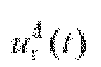
amplitude calculation unit 601 is specifically configured to determine the voltage amplitude of the new energy terminal and the voltage amplitude of the AC bus at any moment after faults of the new energy terminal and the AC bus are cleared respectively according to the following formulas (14) and (15):

[0089] here U r(t) is a voltage amplitude of the new energy terminal at a moment t;


- [0090] Preferably, the overvoltage limit
ratio determination unit 602 is configured to determine an overvoltage limit ratio according to a ratio of the voltage amplitude of the new energy terminal to the voltage amplitude of the AC bus. - [0091] Preferably, the critical overvoltage limit
ratio determination unit 603 is configured to determine a critical overvoltage limit ratio. - [0092] Preferably, the critical overvoltage limit
ratio determination unit 603 is specifically configured to determine the critical overvoltage limit ratio according to the following formula (16):
[0093] here N m is the critical overvoltage limit ratio; 4, is an equivalent reactance between the new energy terminal and the AC bus; U g is an electromotive force of an equivalent power supply of an AC power grid; ω g is an angular frequency of the AC power grid; L p is an equivalent reactance from the AC bus to an infinite power supply; and U sN is a preset overvoltage limit value of the AC bus. - [0094] Preferably, the maximum voltage
value calculation unit 604 is configured to determine a maximum new energy terminal voltage value and a maximum AC bus voltage value bearable for the new energy terminal and the AC bus respectively. - [0095] Preferably, the maximum voltage
value calculation unit 604 is specifically configured to determine the maximum new energy terminal voltage value and the maximum AC bus voltage value bearable for the new energy terminal and the AC bus respectively according to the following formulas (17) and (18):

[0096] here U r_max is the maximum new energy terminal voltage value; U s_max is the maximum AC bus voltage value; U g is an electromotive force of an equivalent power supply of an AC power grid; ω g is an angular frequency of the AC power grid; L Σ is an equivalent reactance from the new energy terminal to an infinite power supply; and L p is an equivalent reactance from the AC bus to the infinite power supply. - [0097] Preferably, the
identification unit 605 is configured to perform identification of a dominant voltage safety constraint according to the overvoltage limit ratio, the critical overvoltage limit ratio, the maximum new energy terminal voltage value and the maximum AC bus voltage value, and determine an identification result. - [0098] Preferably, the
identification unit 605 configured to perform identification of the dominant voltage safety constraint according to the overvoltage limit ratio, the critical overvoltage limit ratio, the maximum new energy terminal voltage value and the maximum AC bus voltage value, and determine the identification result, includes that the identification unit is configured to: - [0099] determine that voltage-exceeding-limit firstly occurs to the new energy terminal, in response to that the voltage amplitude of the new energy terminal is less than or equal to the maximum new energy terminal voltage value, and the overvoltage limit ratio is less than or equal to 1;
- [00100] determine that the voltage-exceeding-limit firstly occurs to the new energy terminal, in response to that the voltage amplitude of the new energy terminal is less than or equal to the maximum new energy terminal voltage value, and the overvoltage limit ratio is greater than 1 and less than the critical overvoltage limit ratio;
- [00101] determine that the voltage-exceeding-limit simultaneously occurs to the new energy terminal and the AC bus, in response to that the voltage amplitude of the new energy terminal is less than or equal to the maximum new energy terminal voltage value, and the overvoltage limit ratio is equal to the critical overvoltage limit ratio; and
- [00102] determine that the voltage-exceeding-limit firstly occurs to the AC bus, in response to that the voltage amplitude of the AC bus is less than or equal to the maximum AC bus voltage value, and the overvoltage limit ratio is greater than the critical overvoltage limit ratio.
- [00103] The
system 600 for identifying a dominant overvoltage of a high-proportion new energy power system according to the embodiment of the disclosure corresponds to themethod 100 for identifying a dominant overvoltage of a high-proportion new energy power system according to another embodiment of the disclosure, and will not be elaborated here. - [00104] According to another aspect of the embodiments of the disclosure, an embodiment of the disclosure provides a computer-readable storage medium, having stored thereon a computer program, the program implements any one of operations of the method for identifying a dominant overvoltage of a high-proportion new energy power system when the program is executed by a processor.
- [00105] According to another aspect of the embodiments of the disclosure, an embodiment of the disclosure provides an electronic device, the electronic device includes the above computer-readable storage medium and one or more processors configured to execute the program in the computer-readable storage medium.
- [00106] According to another aspect of the embodiments of the disclosure, an embodiment of the disclosure provides a computer program product, the computer program product includes a computer instruction, the computer instruction enables a computer device to perform operations of the above method for identifying a dominant overvoltage of a high-proportion new energy power system when the computer instruction is executed on the computer device.
- [00107] The disclosure has been described with reference to a few embodiments. However, it is well known by those skilled in the art that other embodiments of the disclosure except the above disclosed embodiments fall within the scope of the disclosure equivalently, as limited by the appended patent claims.
- [00108] In general, all terms used in the claims are interpreted according to their ordinary meanings in the technical field, unless otherwise explicitly defined there. All references to "a/the/these [device, component, etc.]" are openly interpreted as at least one instance of the device, component, etc., unless otherwise explicitly stated. It is unnecessary for the operations of any method disclosed here to be executed in the exact orders as disclosed, unless explicitly stated.
- [00109] It may be understood by those skilled in the art that the embodiments of the disclosure may be provided as methods, systems or computer program products. Therefore, the disclosure may take forms of embodiments with entire hardware, embodiments with entire software, or embodiments combining software with hardware aspects. Furthermore, the disclosure may take a form of a computer program product implemented on one or more computer-available storage media (including, but not limited to a disk storage, a Compact Disk Read Only Memory (CD-ROM), an optical storage, etc.) containing computer-available program codes.
- [00110] The disclosure is described with reference to flowcharts and/or block diagrams of methods, devices (systems) and computer program products according to the embodiments of the disclosure. It should be understood that computer program instructions may implement each flow and/or block in the flowcharts and/or the block diagrams, as well as combinations of flows and/or blocks in the flowcharts and/or the block diagrams. These computer program instructions may be provided to a processor of a general purpose computer, a specialized computer, an embedded processor or another programmable data processing device to generate a machine, such that instructions executed by the processor of the computer or another programmable data processing device generate a device configured to implement functions specified in one or more flows of the flowcharts and/or one or more blocks of the block diagrams.
- [00111] These computer program instructions may also be stored in a computer-readable memory which may guide a computer or another programmable data processing device to operate in a specific manner, such that the instructions stored in the computer-readable memory generate a manufactured product including an instruction device, and the instruction device implements functions specified in one or more flows of the flowcharts and/or one or more blocks of the block diagrams.
- [00112] These computer program instructions may also be loaded onto a computer or another programmable data processing device, such that a series of operations are executed on the computer or another programmable device to generate computer-implemented processing, and thus the instructions executed on the computer or another programmable device provide operations for implementing functions specified in one or more flows of the flowcharts and/or one or more blocks of the block diagrams.
- [00113] Finally, it should be noted that the above embodiments are only intended to explain technical solutions of the disclosure and are not intended to limit the technical solutions. Although the disclosure has been described in detail with reference to the above embodiments, it should be understood by those of ordinary skill in the art that modifications or equivalent replacements may be still made to specific embodiments of the disclosure, and any modification or equivalent replacement which do not depart from the spirit and scope of the disclosure should fall within the scope of protection of the claims of the disclosure.
Claims (13)
- A method for identifying a dominant overvoltage of a high-proportion new energy power system, comprising:determining a voltage amplitude of a new energy terminal and a voltage amplitude of an alternating-current (AC) bus at any moment after faults of the new energy terminal and the AC bus are cleared respectively;determining an overvoltage limit ratio according to a ratio of the voltage amplitude of the new energy terminal to the voltage amplitude of the AC bus;determining a critical overvoltage limit ratio;determining a maximum new energy terminal voltage value and a maximum AC bus voltage value bearable for the new energy terminal and the AC bus respectively; andperforming identification of a dominant voltage safety constraint according to the overvoltage limit ratio, the critical overvoltage limit ratio, the maximum new energy terminal voltage value and the maximum AC bus voltage value, and determining an identification result.
- The method of claim 1, wherein determining the voltage amplitude of the new energy terminal and the voltage amplitude of the AC bus at any moment after faults of the new energy terminal and the AC bus are cleared respectively, comprises:





- The method of claim 1, wherein determining the critical overvoltage limit ratio comprises:

- The method of claim 1, wherein determining the maximum new energy terminal voltage value and the maximum AC bus voltage value bearable for the new energy terminal and the AC bus respectively comprises:


- The method of claim 1, wherein performing identification of the dominant voltage safety constraint according to the overvoltage limit ratio, the critical overvoltage limit ratio, the maximum new energy terminal voltage value and the maximum AC bus voltage value, and determining the identification result comprise:determining that voltage-exceeding-limit firstly occurs to the new energy terminal, in response to that the voltage amplitude of the new energy terminal is less than or equal to the maximum new energy terminal voltage value, and the overvoltage limit ratio is less than or equal to 1;determining that the voltage-exceeding-limit firstly occurs to the new energy terminal, in response to that the voltage amplitude of the new energy terminal is less than or equal to the maximum new energy terminal voltage value, and the overvoltage limit ratio is greater than 1 and less than the critical overvoltage limit ratio;determining that the voltage-exceeding-limit simultaneously occurs to the new energy terminal and the AC bus, in response to that the voltage amplitude of the new energy terminal is less than or equal to the maximum new energy terminal voltage value, and the overvoltage limit ratio is equal to the critical overvoltage limit ratio; anddetermining that the voltage-exceeding-limit firstly occurs to the AC bus, in response to that the voltage amplitude of the AC bus is less than or equal to the maximum AC bus voltage value, and the overvoltage limit ratio is greater than the critical overvoltage limit ratio.
- A system for identifying a dominant overvoltage of a high-proportion new energy power system, comprising:a voltage amplitude calculation unit, configured to determine a voltage amplitude of a new energy terminal and a voltage amplitude of an alternating-current (AC) bus at any moment after faults of the new energy terminal and the AC bus are cleared respectively;an overvoltage limit ratio determination unit, configured to determine an overvoltage limit ratio according to a ratio of the voltage amplitude of the new energy terminal to the voltage amplitude of the AC bus;a critical overvoltage limit ratio determination unit, configured to determine a critical overvoltage limit ratio;a maximum voltage value calculation unit, configured to determine a maximum new energy terminal voltage value and a maximum AC bus voltage value bearable for the new energy terminal and the AC bus respectively; andan identification unit, configured to perform identification of a dominant voltage safety constraint according to the overvoltage limit ratio, the critical overvoltage limit ratio, the maximum new energy terminal voltage value and the maximum AC bus voltage value, and determine an identification result.
- The system of claim 6, wherein the voltage amplitude calculation unit is specifically configured to determine the voltage amplitude of the new energy terminal and the voltage amplitude of the AC bus at any moment after faults of the new energy terminal and the AC bus are cleared respectively by formulas:


- The system of claim 6, wherein the critical overvoltage limit ratio determination unit is specifically configured to determine the critical overvoltage limit ratio by a formula:

- The system of claim 6, wherein the maximum voltage value calculation unit is specifically configured to determine the maximum new energy terminal voltage value and the maximum AC bus voltage value bearable for the new energy terminal and the AC bus respectively by formulas:


- The system of claim 6, wherein the identification unit is specifically configured to:determine that voltage-exceeding-limit firstly occurs to the new energy terminal, in response to that the voltage amplitude of the new energy terminal is less than or equal to the maximum new energy terminal voltage value, and the overvoltage limit ratio is less than or equal to 1;determine that the voltage-exceeding-limit firstly occurs to the new energy terminal, in response to that the voltage amplitude of the new energy terminal is less than or equal to the maximum new energy terminal voltage value, and the overvoltage limit ratio is greater than 1 and less than the critical overvoltage limit ratio;determine that the voltage-exceeding-limit simultaneously occurs to the new energy terminal and the AC bus, in response to that the voltage amplitude of the new energy terminal is less than or equal to the maximum new energy terminal voltage value, and the overvoltage limit ratio is equal to the critical overvoltage limit ratio; anddetermine that the voltage-exceeding-limit firstly occurs to the AC bus, in response to that the voltage amplitude of the AC bus is less than or equal to the maximum AC bus voltage value, and the overvoltage limit ratio is greater than the critical overvoltage limit ratio.
- A computer-readable storage medium, having stored thereon a computer program, the program implementing steps of the method of any one of claims 1 to 5 when the program is executed by a processor.
- An electronic device, comprising:the computer-readable storage medium of claim 11; andone or more processors, configured to execute the program in the computer-readable storage medium.
- A computer program product, comprising a computer instruction, the computer instruction enabling a computer device to perform steps of the method of any one of claims 1 to 5 when the computer instruction is executed on the computer device.
Applications Claiming Priority (2)
| Application Number | Priority Date | Filing Date | Title |
|---|---|---|---|
| CN202210475787.1A CN115842327A (en) | 2022-04-29 | 2022-04-29 | Method and system for identifying dominant overvoltage of high-proportion new energy power system |
| PCT/CN2022/136790 WO2023207099A1 (en) | 2022-04-29 | 2022-12-06 | Method and system for identifying dominant overvoltage of a high-proportion new energy power system, electronic device, storage medium, and computer program product |
Publications (3)
| Publication Number | Publication Date |
|---|---|
| EP4350918A1 true EP4350918A1 (en) | 2024-04-10 |
| EP4350918A4 EP4350918A4 (en) | 2024-11-13 |
| EP4350918B1 EP4350918B1 (en) | 2025-11-05 |
Family
ID=85574702
Family Applications (1)
| Application Number | Title | Priority Date | Filing Date |
|---|---|---|---|
| EP22939913.4A Active EP4350918B1 (en) | 2022-04-29 | 2022-12-06 | Method and system for identifying dominant overvoltage of a high-proportion new energy power system, electronic device, storage medium, and computer program product |
Country Status (5)
| Country | Link |
|---|---|
| US (1) | US20240235184A1 (en) |
| EP (1) | EP4350918B1 (en) |
| CN (1) | CN115842327A (en) |
| AU (1) | AU2022455910B2 (en) |
| WO (1) | WO2023207099A1 (en) |
Families Citing this family (1)
| Publication number | Priority date | Publication date | Assignee | Title |
|---|---|---|---|---|
| CN119787381B (en) * | 2024-12-30 | 2025-10-03 | 西南交通大学 | A new energy reactive power control method for transient overvoltage suppression in DC power grid |
Family Cites Families (6)
| Publication number | Priority date | Publication date | Assignee | Title |
|---|---|---|---|---|
| CN109659969B (en) * | 2019-02-15 | 2019-11-15 | 四川大学 | A method for judging and controlling dynamic stability of flexible direct current transmission |
| CN112560222B (en) * | 2020-11-16 | 2024-08-09 | 国网辽宁省电力有限公司电力科学研究院 | Reactive power optimization configuration method for improving dynamic stability of power grid |
| CN113705138A (en) * | 2021-08-30 | 2021-11-26 | 国网上海市电力公司 | Online safety assessment method for large-scale alternating current and direct current power grid |
| CN113890083B (en) * | 2021-08-31 | 2023-09-01 | 华为数字能源技术有限公司 | Power converter control method, control device and computer storage medium |
| CN113783232B (en) * | 2021-11-09 | 2022-02-11 | 中国电力科学研究院有限公司 | A method and device for monitoring the synchronization safety and stability of a new energy grid-connected system |
| CN114118546A (en) * | 2021-11-15 | 2022-03-01 | 中国电力科学研究院有限公司 | Overvoltage risk assessment method and system for high-proportion new energy power system |
-
2022
- 2022-04-29 CN CN202210475787.1A patent/CN115842327A/en active Pending
- 2022-12-06 AU AU2022455910A patent/AU2022455910B2/en active Active
- 2022-12-06 WO PCT/CN2022/136790 patent/WO2023207099A1/en not_active Ceased
- 2022-12-06 EP EP22939913.4A patent/EP4350918B1/en active Active
- 2022-12-06 US US18/559,561 patent/US20240235184A1/en active Pending
Also Published As
| Publication number | Publication date |
|---|---|
| EP4350918B1 (en) | 2025-11-05 |
| US20240235184A1 (en) | 2024-07-11 |
| WO2023207099A1 (en) | 2023-11-02 |
| EP4350918A4 (en) | 2024-11-13 |
| CN115842327A (en) | 2023-03-24 |
| AU2022455910A1 (en) | 2023-12-21 |
| AU2022455910B2 (en) | 2024-10-24 |
Similar Documents
| Publication | Publication Date | Title |
|---|---|---|
| US11146063B1 (en) | Renewable power transmission line using the square error method | |
| US9742192B2 (en) | Method and system for island detection and anti-islanding protection in distributed power generation systems | |
| US20250167541A1 (en) | Active Arc Voltage-Current Conversion Method, System, and Medium for Distribution Networks | |
| CN112467733B (en) | A kind of active power injection full compensation arc suppression coil active withdrawal method | |
| CN102882193A (en) | Method and system for traveling wave protection setting of high-voltage direct-current transmission line | |
| EP4297218A1 (en) | Low-capacitive-reactance protection method and system, and computer-readable storage medium and computer program product | |
| EP3639336B1 (en) | Method for detecting fault in power transmission line and protection system using the same | |
| US11962150B1 (en) | System and method of protecting power system having inverter-interfaced renewable energy sources | |
| Trevisan et al. | Analysis of low frequency interactions of DFIG wind turbine systems in series compensated grids | |
| EP4507152B1 (en) | Method and apparatus for determining voltage support strength of new-energy power system in real time, and device, storage medium and computer program product | |
| EP4350918B1 (en) | Method and system for identifying dominant overvoltage of a high-proportion new energy power system, electronic device, storage medium, and computer program product | |
| Nasr et al. | Power swing in systems with inverter-based resources—Part II: Impact on protection systems | |
| Liemann et al. | Voltage stability analysis of grid-forming converters with current limitation | |
| CN115833225A (en) | VSG Transient Stability Interval Analysis Method Considering the Effect of Current Limiting Link | |
| CN117277247B (en) | A fault rotation arc extinguishing method and system for small current grounding system distribution network | |
| JP7289748B2 (en) | Evaluation method for determining the islanding detection limit of a system connected to a PCS that does not use an active system | |
| Jaiswal et al. | Reinforcement learning based islanding detection technique in distributed generation | |
| Al-Kaoaz et al. | Performance enhancement of distance relay in presence of unified power flow controller | |
| US20250192547A1 (en) | Arc suppression method, system, and medium for distribution network faults based on closed-loop self-healing control | |
| Eberlein | Small-signal stability modelling and optimization of microgrids | |
| Liao et al. | A study on HVDC overcurrent during commutation failure | |
| Wenig et al. | Internal converter-and DC-fault handling for a single point grounded bipolar MMC-HVDC system | |
| Wijayalath et al. | Comparative Analysis of Grid-Forming Inverters: Influence of Control Parameters and Grid Conditions on Transient Stability | |
| Changizian et al. | An improved control method for limiting current in VSC-HVDC system under unbalanced conditions | |
| Radecic et al. | Investigation of resonance between HVDC-MMC link and AC network |
Legal Events
| Date | Code | Title | Description |
|---|---|---|---|
| STAA | Information on the status of an ep patent application or granted ep patent |
Free format text: STATUS: THE INTERNATIONAL PUBLICATION HAS BEEN MADE |
|
| PUAI | Public reference made under article 153(3) epc to a published international application that has entered the european phase |
Free format text: ORIGINAL CODE: 0009012 |
|
| STAA | Information on the status of an ep patent application or granted ep patent |
Free format text: STATUS: REQUEST FOR EXAMINATION WAS MADE |
|
| 17P | Request for examination filed |
Effective date: 20240104 |
|
| AK | Designated contracting states |
Kind code of ref document: A1 Designated state(s): AL AT BE BG CH CY CZ DE DK EE ES FI FR GB GR HR HU IE IS IT LI LT LU LV MC ME MK MT NL NO PL PT RO RS SE SI SK SM TR |
|
| A4 | Supplementary search report drawn up and despatched |
Effective date: 20241010 |
|
| RIC1 | Information provided on ipc code assigned before grant |
Ipc: H02J 3/00 20060101ALI20241004BHEP Ipc: H02H 3/20 20060101ALI20241004BHEP Ipc: G06Q 50/06 20240101ALI20241004BHEP Ipc: H02J 3/40 20060101ALI20241004BHEP Ipc: H02H 7/22 20060101AFI20241004BHEP |
|
| REG | Reference to a national code |
Ref country code: DE Free format text: PREVIOUS MAIN CLASS: H02H0007220000 Ref country code: DE Ref legal event code: R079 Ref document number: 602022024701 Country of ref document: DE Free format text: PREVIOUS MAIN CLASS: H02H0007220000 Ipc: G06Q0010063500 |
|
| GRAP | Despatch of communication of intention to grant a patent |
Free format text: ORIGINAL CODE: EPIDOSNIGR1 |
|
| STAA | Information on the status of an ep patent application or granted ep patent |
Free format text: STATUS: GRANT OF PATENT IS INTENDED |
|
| RIC1 | Information provided on ipc code assigned before grant |
Ipc: H02J 3/00 20060101ALI20250526BHEP Ipc: H02H 3/20 20060101ALI20250526BHEP Ipc: G06Q 50/06 20240101ALI20250526BHEP Ipc: G06Q 10/0635 20230101AFI20250526BHEP |
|
| DAV | Request for validation of the european patent (deleted) | ||
| DAX | Request for extension of the european patent (deleted) | ||
| INTG | Intention to grant announced |
Effective date: 20250611 |
|
| GRAS | Grant fee paid |
Free format text: ORIGINAL CODE: EPIDOSNIGR3 |
|
| GRAA | (expected) grant |
Free format text: ORIGINAL CODE: 0009210 |
|
| STAA | Information on the status of an ep patent application or granted ep patent |
Free format text: STATUS: THE PATENT HAS BEEN GRANTED |
|
| AK | Designated contracting states |
Kind code of ref document: B1 Designated state(s): AL AT BE BG CH CY CZ DE DK EE ES FI FR GB GR HR HU IE IS IT LI LT LU LV MC ME MK MT NL NO PL PT RO RS SE SI SK SM TR |
|
| REG | Reference to a national code |
Ref country code: CH Ref legal event code: F10 Free format text: ST27 STATUS EVENT CODE: U-0-0-F10-F00 (AS PROVIDED BY THE NATIONAL OFFICE) Effective date: 20251105 Ref country code: GB Ref legal event code: FG4D |
|
| REG | Reference to a national code |
Ref country code: DE Ref legal event code: R096 Ref document number: 602022024701 Country of ref document: DE |
|
| REG | Reference to a national code |
Ref country code: IE Ref legal event code: FG4D |
|
| PGFP | Annual fee paid to national office [announced via postgrant information from national office to epo] |
Ref country code: AT Payment date: 20260113 Year of fee payment: 4 |
|
| REG | Reference to a national code |
Ref country code: NL Ref legal event code: MP Effective date: 20251105 |
|
| PG25 | Lapsed in a contracting state [announced via postgrant information from national office to epo] |
Ref country code: ES Free format text: LAPSE BECAUSE OF FAILURE TO SUBMIT A TRANSLATION OF THE DESCRIPTION OR TO PAY THE FEE WITHIN THE PRESCRIBED TIME-LIMIT Effective date: 20251105 |
|
| REG | Reference to a national code |
Ref country code: LT Ref legal event code: MG9D |
|
| PG25 | Lapsed in a contracting state [announced via postgrant information from national office to epo] |
Ref country code: NO Free format text: LAPSE BECAUSE OF FAILURE TO SUBMIT A TRANSLATION OF THE DESCRIPTION OR TO PAY THE FEE WITHIN THE PRESCRIBED TIME-LIMIT Effective date: 20260205 |
|
| PGFP | Annual fee paid to national office [announced via postgrant information from national office to epo] |
Ref country code: DE Payment date: 20260108 Year of fee payment: 4 |
|
| PG25 | Lapsed in a contracting state [announced via postgrant information from national office to epo] |
Ref country code: AT Free format text: LAPSE BECAUSE OF FAILURE TO SUBMIT A TRANSLATION OF THE DESCRIPTION OR TO PAY THE FEE WITHIN THE PRESCRIBED TIME-LIMIT Effective date: 20251105 Ref country code: FI Free format text: LAPSE BECAUSE OF FAILURE TO SUBMIT A TRANSLATION OF THE DESCRIPTION OR TO PAY THE FEE WITHIN THE PRESCRIBED TIME-LIMIT Effective date: 20251105 Ref country code: HR Free format text: LAPSE BECAUSE OF FAILURE TO SUBMIT A TRANSLATION OF THE DESCRIPTION OR TO PAY THE FEE WITHIN THE PRESCRIBED TIME-LIMIT Effective date: 20251105 |
|
| REG | Reference to a national code |
Ref country code: AT Ref legal event code: MK05 Ref document number: 1855166 Country of ref document: AT Kind code of ref document: T Effective date: 20251105 |
|
| PG25 | Lapsed in a contracting state [announced via postgrant information from national office to epo] |
Ref country code: NL Free format text: LAPSE BECAUSE OF FAILURE TO SUBMIT A TRANSLATION OF THE DESCRIPTION OR TO PAY THE FEE WITHIN THE PRESCRIBED TIME-LIMIT Effective date: 20251105 |
|
| PG25 | Lapsed in a contracting state [announced via postgrant information from national office to epo] |
Ref country code: RS Free format text: LAPSE BECAUSE OF FAILURE TO SUBMIT A TRANSLATION OF THE DESCRIPTION OR TO PAY THE FEE WITHIN THE PRESCRIBED TIME-LIMIT Effective date: 20260205 |
|
| PG25 | Lapsed in a contracting state [announced via postgrant information from national office to epo] |
Ref country code: IS Free format text: LAPSE BECAUSE OF FAILURE TO SUBMIT A TRANSLATION OF THE DESCRIPTION OR TO PAY THE FEE WITHIN THE PRESCRIBED TIME-LIMIT Effective date: 20260305 |
|
| PG25 | Lapsed in a contracting state [announced via postgrant information from national office to epo] |
Ref country code: PT Free format text: LAPSE BECAUSE OF FAILURE TO SUBMIT A TRANSLATION OF THE DESCRIPTION OR TO PAY THE FEE WITHIN THE PRESCRIBED TIME-LIMIT Effective date: 20260305 |
|
| PG25 | Lapsed in a contracting state [announced via postgrant information from national office to epo] |
Ref country code: PL Free format text: LAPSE BECAUSE OF FAILURE TO SUBMIT A TRANSLATION OF THE DESCRIPTION OR TO PAY THE FEE WITHIN THE PRESCRIBED TIME-LIMIT Effective date: 20251105 |
|
| PG25 | Lapsed in a contracting state [announced via postgrant information from national office to epo] |
Ref country code: LV Free format text: LAPSE BECAUSE OF FAILURE TO SUBMIT A TRANSLATION OF THE DESCRIPTION OR TO PAY THE FEE WITHIN THE PRESCRIBED TIME-LIMIT Effective date: 20251105 |
|
| PG25 | Lapsed in a contracting state [announced via postgrant information from national office to epo] |
Ref country code: BG Free format text: LAPSE BECAUSE OF FAILURE TO SUBMIT A TRANSLATION OF THE DESCRIPTION OR TO PAY THE FEE WITHIN THE PRESCRIBED TIME-LIMIT Effective date: 20251105 |