EP4350850A2 - Cylindrical secondary battery - Google Patents
Cylindrical secondary battery Download PDFInfo
- Publication number
- EP4350850A2 EP4350850A2 EP23200525.6A EP23200525A EP4350850A2 EP 4350850 A2 EP4350850 A2 EP 4350850A2 EP 23200525 A EP23200525 A EP 23200525A EP 4350850 A2 EP4350850 A2 EP 4350850A2
- Authority
- EP
- European Patent Office
- Prior art keywords
- plate
- secondary battery
- cylindrical secondary
- electrode
- head
- Prior art date
- Legal status (The legal status is an assumption and is not a legal conclusion. Google has not performed a legal analysis and makes no representation as to the accuracy of the status listed.)
- Pending
Links
Images



Classifications
-
- H—ELECTRICITY
- H01—ELECTRIC ELEMENTS
- H01M—PROCESSES OR MEANS, e.g. BATTERIES, FOR THE DIRECT CONVERSION OF CHEMICAL ENERGY INTO ELECTRICAL ENERGY
- H01M50/00—Constructional details or processes of manufacture of the non-active parts of electrochemical cells other than fuel cells, e.g. hybrid cells
- H01M50/10—Primary casings; Jackets or wrappings
- H01M50/172—Arrangements of electric connectors penetrating the casing
- H01M50/174—Arrangements of electric connectors penetrating the casing adapted for the shape of the cells
- H01M50/179—Arrangements of electric connectors penetrating the casing adapted for the shape of the cells for cells having curved cross-section, e.g. round or elliptic
-
- H—ELECTRICITY
- H01—ELECTRIC ELEMENTS
- H01M—PROCESSES OR MEANS, e.g. BATTERIES, FOR THE DIRECT CONVERSION OF CHEMICAL ENERGY INTO ELECTRICAL ENERGY
- H01M50/00—Constructional details or processes of manufacture of the non-active parts of electrochemical cells other than fuel cells, e.g. hybrid cells
- H01M50/50—Current conducting connections for cells or batteries
- H01M50/572—Means for preventing undesired use or discharge
- H01M50/574—Devices or arrangements for the interruption of current
- H01M50/583—Devices or arrangements for the interruption of current in response to current, e.g. fuses
-
- H—ELECTRICITY
- H01—ELECTRIC ELEMENTS
- H01M—PROCESSES OR MEANS, e.g. BATTERIES, FOR THE DIRECT CONVERSION OF CHEMICAL ENERGY INTO ELECTRICAL ENERGY
- H01M50/00—Constructional details or processes of manufacture of the non-active parts of electrochemical cells other than fuel cells, e.g. hybrid cells
- H01M50/10—Primary casings; Jackets or wrappings
- H01M50/147—Lids or covers
- H01M50/148—Lids or covers characterised by their shape
- H01M50/152—Lids or covers characterised by their shape for cells having curved cross-section, e.g. round or elliptic
-
- H—ELECTRICITY
- H01—ELECTRIC ELEMENTS
- H01M—PROCESSES OR MEANS, e.g. BATTERIES, FOR THE DIRECT CONVERSION OF CHEMICAL ENERGY INTO ELECTRICAL ENERGY
- H01M50/00—Constructional details or processes of manufacture of the non-active parts of electrochemical cells other than fuel cells, e.g. hybrid cells
- H01M50/10—Primary casings; Jackets or wrappings
- H01M50/102—Primary casings; Jackets or wrappings characterised by their shape or physical structure
- H01M50/107—Primary casings; Jackets or wrappings characterised by their shape or physical structure having curved cross-section, e.g. round or elliptic
-
- H—ELECTRICITY
- H01—ELECTRIC ELEMENTS
- H01M—PROCESSES OR MEANS, e.g. BATTERIES, FOR THE DIRECT CONVERSION OF CHEMICAL ENERGY INTO ELECTRICAL ENERGY
- H01M50/00—Constructional details or processes of manufacture of the non-active parts of electrochemical cells other than fuel cells, e.g. hybrid cells
- H01M50/10—Primary casings; Jackets or wrappings
- H01M50/116—Primary casings; Jackets or wrappings characterised by the material
- H01M50/117—Inorganic material
- H01M50/119—Metals
-
- H—ELECTRICITY
- H01—ELECTRIC ELEMENTS
- H01M—PROCESSES OR MEANS, e.g. BATTERIES, FOR THE DIRECT CONVERSION OF CHEMICAL ENERGY INTO ELECTRICAL ENERGY
- H01M50/00—Constructional details or processes of manufacture of the non-active parts of electrochemical cells other than fuel cells, e.g. hybrid cells
- H01M50/10—Primary casings; Jackets or wrappings
- H01M50/147—Lids or covers
- H01M50/148—Lids or covers characterised by their shape
- H01M50/154—Lid or cover comprising an axial bore for receiving a central current collector
-
- H—ELECTRICITY
- H01—ELECTRIC ELEMENTS
- H01M—PROCESSES OR MEANS, e.g. BATTERIES, FOR THE DIRECT CONVERSION OF CHEMICAL ENERGY INTO ELECTRICAL ENERGY
- H01M50/00—Constructional details or processes of manufacture of the non-active parts of electrochemical cells other than fuel cells, e.g. hybrid cells
- H01M50/10—Primary casings; Jackets or wrappings
- H01M50/147—Lids or covers
- H01M50/155—Lids or covers characterised by the material
- H01M50/157—Inorganic material
- H01M50/159—Metals
-
- H—ELECTRICITY
- H01—ELECTRIC ELEMENTS
- H01M—PROCESSES OR MEANS, e.g. BATTERIES, FOR THE DIRECT CONVERSION OF CHEMICAL ENERGY INTO ELECTRICAL ENERGY
- H01M50/00—Constructional details or processes of manufacture of the non-active parts of electrochemical cells other than fuel cells, e.g. hybrid cells
- H01M50/10—Primary casings; Jackets or wrappings
- H01M50/183—Sealing members
- H01M50/184—Sealing members characterised by their shape or structure
-
- H—ELECTRICITY
- H01—ELECTRIC ELEMENTS
- H01M—PROCESSES OR MEANS, e.g. BATTERIES, FOR THE DIRECT CONVERSION OF CHEMICAL ENERGY INTO ELECTRICAL ENERGY
- H01M50/00—Constructional details or processes of manufacture of the non-active parts of electrochemical cells other than fuel cells, e.g. hybrid cells
- H01M50/10—Primary casings; Jackets or wrappings
- H01M50/183—Sealing members
- H01M50/186—Sealing members characterised by the disposition of the sealing members
-
- H—ELECTRICITY
- H01—ELECTRIC ELEMENTS
- H01M—PROCESSES OR MEANS, e.g. BATTERIES, FOR THE DIRECT CONVERSION OF CHEMICAL ENERGY INTO ELECTRICAL ENERGY
- H01M50/00—Constructional details or processes of manufacture of the non-active parts of electrochemical cells other than fuel cells, e.g. hybrid cells
- H01M50/30—Arrangements for facilitating escape of gases
- H01M50/342—Non-re-sealable arrangements
- H01M50/3425—Non-re-sealable arrangements in the form of rupturable membranes or weakened parts, e.g. pierced with the aid of a sharp member
-
- H—ELECTRICITY
- H01—ELECTRIC ELEMENTS
- H01M—PROCESSES OR MEANS, e.g. BATTERIES, FOR THE DIRECT CONVERSION OF CHEMICAL ENERGY INTO ELECTRICAL ENERGY
- H01M50/00—Constructional details or processes of manufacture of the non-active parts of electrochemical cells other than fuel cells, e.g. hybrid cells
- H01M50/40—Separators; Membranes; Diaphragms; Spacing elements inside cells
- H01M50/471—Spacing elements inside cells other than separators, membranes or diaphragms; Manufacturing processes thereof
- H01M50/474—Spacing elements inside cells other than separators, membranes or diaphragms; Manufacturing processes thereof characterised by their position inside the cells
-
- H—ELECTRICITY
- H01—ELECTRIC ELEMENTS
- H01M—PROCESSES OR MEANS, e.g. BATTERIES, FOR THE DIRECT CONVERSION OF CHEMICAL ENERGY INTO ELECTRICAL ENERGY
- H01M50/00—Constructional details or processes of manufacture of the non-active parts of electrochemical cells other than fuel cells, e.g. hybrid cells
- H01M50/40—Separators; Membranes; Diaphragms; Spacing elements inside cells
- H01M50/471—Spacing elements inside cells other than separators, membranes or diaphragms; Manufacturing processes thereof
- H01M50/477—Spacing elements inside cells other than separators, membranes or diaphragms; Manufacturing processes thereof characterised by their shape
-
- H—ELECTRICITY
- H01—ELECTRIC ELEMENTS
- H01M—PROCESSES OR MEANS, e.g. BATTERIES, FOR THE DIRECT CONVERSION OF CHEMICAL ENERGY INTO ELECTRICAL ENERGY
- H01M50/00—Constructional details or processes of manufacture of the non-active parts of electrochemical cells other than fuel cells, e.g. hybrid cells
- H01M50/40—Separators; Membranes; Diaphragms; Spacing elements inside cells
- H01M50/471—Spacing elements inside cells other than separators, membranes or diaphragms; Manufacturing processes thereof
- H01M50/48—Spacing elements inside cells other than separators, membranes or diaphragms; Manufacturing processes thereof characterised by the material
- H01M50/483—Inorganic material
-
- H—ELECTRICITY
- H01—ELECTRIC ELEMENTS
- H01M—PROCESSES OR MEANS, e.g. BATTERIES, FOR THE DIRECT CONVERSION OF CHEMICAL ENERGY INTO ELECTRICAL ENERGY
- H01M50/00—Constructional details or processes of manufacture of the non-active parts of electrochemical cells other than fuel cells, e.g. hybrid cells
- H01M50/40—Separators; Membranes; Diaphragms; Spacing elements inside cells
- H01M50/471—Spacing elements inside cells other than separators, membranes or diaphragms; Manufacturing processes thereof
- H01M50/48—Spacing elements inside cells other than separators, membranes or diaphragms; Manufacturing processes thereof characterised by the material
- H01M50/486—Organic material
-
- H—ELECTRICITY
- H01—ELECTRIC ELEMENTS
- H01M—PROCESSES OR MEANS, e.g. BATTERIES, FOR THE DIRECT CONVERSION OF CHEMICAL ENERGY INTO ELECTRICAL ENERGY
- H01M50/00—Constructional details or processes of manufacture of the non-active parts of electrochemical cells other than fuel cells, e.g. hybrid cells
- H01M50/50—Current conducting connections for cells or batteries
- H01M50/531—Electrode connections inside a battery casing
-
- H—ELECTRICITY
- H01—ELECTRIC ELEMENTS
- H01M—PROCESSES OR MEANS, e.g. BATTERIES, FOR THE DIRECT CONVERSION OF CHEMICAL ENERGY INTO ELECTRICAL ENERGY
- H01M50/00—Constructional details or processes of manufacture of the non-active parts of electrochemical cells other than fuel cells, e.g. hybrid cells
- H01M50/50—Current conducting connections for cells or batteries
- H01M50/531—Electrode connections inside a battery casing
- H01M50/538—Connection of several leads or tabs of wound or folded electrode stacks
-
- H—ELECTRICITY
- H01—ELECTRIC ELEMENTS
- H01M—PROCESSES OR MEANS, e.g. BATTERIES, FOR THE DIRECT CONVERSION OF CHEMICAL ENERGY INTO ELECTRICAL ENERGY
- H01M50/00—Constructional details or processes of manufacture of the non-active parts of electrochemical cells other than fuel cells, e.g. hybrid cells
- H01M50/50—Current conducting connections for cells or batteries
- H01M50/543—Terminals
- H01M50/547—Terminals characterised by the disposition of the terminals on the cells
- H01M50/55—Terminals characterised by the disposition of the terminals on the cells on the same side of the cell
-
- H—ELECTRICITY
- H01—ELECTRIC ELEMENTS
- H01M—PROCESSES OR MEANS, e.g. BATTERIES, FOR THE DIRECT CONVERSION OF CHEMICAL ENERGY INTO ELECTRICAL ENERGY
- H01M50/00—Constructional details or processes of manufacture of the non-active parts of electrochemical cells other than fuel cells, e.g. hybrid cells
- H01M50/50—Current conducting connections for cells or batteries
- H01M50/543—Terminals
- H01M50/552—Terminals characterised by their shape
- H01M50/559—Terminals adapted for cells having curved cross-section, e.g. round, elliptic or button cells
-
- H—ELECTRICITY
- H01—ELECTRIC ELEMENTS
- H01M—PROCESSES OR MEANS, e.g. BATTERIES, FOR THE DIRECT CONVERSION OF CHEMICAL ENERGY INTO ELECTRICAL ENERGY
- H01M50/00—Constructional details or processes of manufacture of the non-active parts of electrochemical cells other than fuel cells, e.g. hybrid cells
- H01M50/50—Current conducting connections for cells or batteries
- H01M50/543—Terminals
- H01M50/564—Terminals characterised by their manufacturing process
- H01M50/566—Terminals characterised by their manufacturing process by welding, soldering or brazing
-
- H—ELECTRICITY
- H01—ELECTRIC ELEMENTS
- H01M—PROCESSES OR MEANS, e.g. BATTERIES, FOR THE DIRECT CONVERSION OF CHEMICAL ENERGY INTO ELECTRICAL ENERGY
- H01M50/00—Constructional details or processes of manufacture of the non-active parts of electrochemical cells other than fuel cells, e.g. hybrid cells
- H01M50/50—Current conducting connections for cells or batteries
- H01M50/543—Terminals
- H01M50/564—Terminals characterised by their manufacturing process
- H01M50/567—Terminals characterised by their manufacturing process by fixing means, e.g. screws, rivets or bolts
-
- H—ELECTRICITY
- H01—ELECTRIC ELEMENTS
- H01M—PROCESSES OR MEANS, e.g. BATTERIES, FOR THE DIRECT CONVERSION OF CHEMICAL ENERGY INTO ELECTRICAL ENERGY
- H01M50/00—Constructional details or processes of manufacture of the non-active parts of electrochemical cells other than fuel cells, e.g. hybrid cells
- H01M50/50—Current conducting connections for cells or batteries
- H01M50/572—Means for preventing undesired use or discharge
- H01M50/574—Devices or arrangements for the interruption of current
- H01M50/578—Devices or arrangements for the interruption of current in response to pressure
-
- H—ELECTRICITY
- H01—ELECTRIC ELEMENTS
- H01M—PROCESSES OR MEANS, e.g. BATTERIES, FOR THE DIRECT CONVERSION OF CHEMICAL ENERGY INTO ELECTRICAL ENERGY
- H01M50/00—Constructional details or processes of manufacture of the non-active parts of electrochemical cells other than fuel cells, e.g. hybrid cells
- H01M50/50—Current conducting connections for cells or batteries
- H01M50/572—Means for preventing undesired use or discharge
- H01M50/574—Devices or arrangements for the interruption of current
- H01M50/581—Devices or arrangements for the interruption of current in response to temperature
-
- H—ELECTRICITY
- H01—ELECTRIC ELEMENTS
- H01M—PROCESSES OR MEANS, e.g. BATTERIES, FOR THE DIRECT CONVERSION OF CHEMICAL ENERGY INTO ELECTRICAL ENERGY
- H01M50/00—Constructional details or processes of manufacture of the non-active parts of electrochemical cells other than fuel cells, e.g. hybrid cells
- H01M50/50—Current conducting connections for cells or batteries
- H01M50/572—Means for preventing undesired use or discharge
- H01M50/584—Means for preventing undesired use or discharge for preventing incorrect connections inside or outside the batteries
- H01M50/59—Means for preventing undesired use or discharge for preventing incorrect connections inside or outside the batteries characterised by the protection means
- H01M50/593—Spacers; Insulating plates
-
- H—ELECTRICITY
- H01—ELECTRIC ELEMENTS
- H01M—PROCESSES OR MEANS, e.g. BATTERIES, FOR THE DIRECT CONVERSION OF CHEMICAL ENERGY INTO ELECTRICAL ENERGY
- H01M2200/00—Safety devices for primary or secondary batteries
- H01M2200/10—Temperature sensitive devices
- H01M2200/103—Fuse
-
- Y—GENERAL TAGGING OF NEW TECHNOLOGICAL DEVELOPMENTS; GENERAL TAGGING OF CROSS-SECTIONAL TECHNOLOGIES SPANNING OVER SEVERAL SECTIONS OF THE IPC; TECHNICAL SUBJECTS COVERED BY FORMER USPC CROSS-REFERENCE ART COLLECTIONS [XRACs] AND DIGESTS
- Y02—TECHNOLOGIES OR APPLICATIONS FOR MITIGATION OR ADAPTATION AGAINST CLIMATE CHANGE
- Y02E—REDUCTION OF GREENHOUSE GAS [GHG] EMISSIONS, RELATED TO ENERGY GENERATION, TRANSMISSION OR DISTRIBUTION
- Y02E60/00—Enabling technologies; Technologies with a potential or indirect contribution to GHG emissions mitigation
- Y02E60/10—Energy storage using batteries
Definitions
- aspects of embodiments of the present disclosure relate to a cylindrical secondary battery.
- a cylindrical secondary battery has an electrode assembly wound in a cylindrical shape accommodated together with an electrolyte in a cylindrical can, which is then sealed with a cap plate.
- the cap plate may be provided with a cap-up or a rivet terminal as a structure acting as a positive terminal.
- the rivet terminal is thicker than the cap-up structure because it requires physical coupling strength to maintain a compressive force on a gasket.
- soldering bonding is structurally impossible, a fusible link which allows for current to be cut off by being melted by high current is not feasible.
- aspects of embodiments of the present disclosure provide a cylindrical secondary battery having a current blocking function.
- a cylindrical secondary battery includes: a cylindrical can; a cap plate coupled to the can, the cap plate having a convex area, a concave area, and an opening; an electrode assembly accommodated in the can and including a first electrode plate and a second electrode plate; and a first terminal exposed to the outside of the cap plate through the opening and having a convex area and a concave area.
- the convex areas and the concave areas of the cap plate and the first terminal are alternately arranged.
- the first terminal may include: a base block electrically connected to the first electrode plate; a head facing the base block and exposed to the outside through the opening; and a fusible link connecting the base block and the head and having a diameter less than that of the head.
- the base block may include: a first protrusion protruding from an edge of a top surface thereof toward the head; a second protrusion protruding from a center thereof toward the head; and a groove recessed between the first protrusion and the second protrusion.
- the cap plate may include: a flat first plate part; a second plate part parallel to the first plate part; an inclined part inclined upwardly from the first plate part and extending between the first plate part and the second plate part; and an extension part extending from the second plate part toward the base block.
- the second plate part and the first protrusion may face each other, and the extension part and the groove may face each other.
- the first terminal may further include an insulation member between the base block and the head.
- the insulation member may be a glass to metal sealing material.
- the cylindrical secondary battery may further include: a first electrode collector plate electrically connected to the first electrode plate and the first terminal; and a second electrode collector plate electrically connected to the second electrode plate and the can.
- Opposite ends of the can may be open.
- the cap plate may be coupled to one open end, and a circular bottom plate may be coupled to the other open end.
- the first electrode collector plate may be between the electrode assembly and the cap plate, and the second electrode collector plate may be between the electrode assembly and the bottom plate.
- a surface of the second plate part may protrude further outwardly than a surface of the head.
- the insulation member may include a protrusion protruding further outwardly than a surface of the head.
- Embodiments of the present disclosure may be embodied in many different forms and should not be construed as being limited to the embodiments described herein. Rather, these embodiments are provided so that this disclosure will be thorough and complete and will fully convey the scope of the present disclosure to those skilled in the art.
- the expression "at least one of a, b, or c" indicates only a, only b, only c, both a and b, both a and c, both b and c, all of a, b, and c, or variations thereof.
- the terms “use,” “using,” and “used” may be considered synonymous with the terms “utilize,” “utilizing,” and “utilized,” respectively.
- the terms “substantially,” “about,” and similar terms are used as terms of approximation and not as terms of degree, and are intended to account for the inherent variations in measured or calculated values that would be recognized by those of ordinary skill in the art.
- first, second, third, etc. may be used herein to describe various elements, components, regions, layers, and/or sections, these elements, components, regions, layers, and/or sections should not be limited by these terms. These terms are used to distinguish one element, component, region, layer, or section from another element, component, region, layer, or section. Thus, a first element, component, region, layer, or section discussed below could be termed a second element, component, region, layer, or section without departing from the teachings of example embodiments.
- spatially relative terms such as “beneath,” “below,” “lower,” “above,” “upper,” and the like, may be used herein for ease of description to describe one element or feature's relationship to another element(s) or feature(s) referring to the figures. It will be understood that the spatially relative terms are intended to encompass different orientations of the device in use or operation in addition to the orientation depicted in the figures. For example, if the device in the figures is turned over, elements described as “below” or “beneath” other elements or features would then be oriented “above” or “over” the other elements or features. Thus, the term “below” may encompass both an orientation of above and below. The device may be otherwise oriented (rotated 90 degrees or at other orientations), and the spatially relative descriptors used herein should be interpreted accordingly.
- an upper side is defined as an upper portion
- a lower side is defined as a lower portion based on the orientation of FIG. 1 .
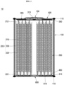
- FIG. 1 is a schematic cross-sectional view of a cylindrical secondary battery according to an embodiment.
- FIG. 2 illustrates an enlarged cross-sectional view of a cap plate and a first terminal of the cylindrical secondary battery shown in FIG. 1 .
- FIG. 3 illustrates an enlarged cross-sectional view of a bottom plate the cylindrical secondary battery shown in FIG. 1 .
- a cylindrical secondary battery 10 may include a cylindrical can 100, a cap plate 500 coupled to one end of the can 100, and a bottom plate 600 coupled to another end (e.g., an opposite end) of the can 100.
- the electrode assembly 200 may be accommodated together with an electrolyte in the can 100.
- the electrode assembly 200 may be electrically connected to a first electrode collector plate 300 and a second electrode collector plate 400 and may be electrically connected to a first terminal 700 and the can 100.
- the electrode assembly 200, connected to the first electrode collector plate 300 and the second electrode collector plate 400 may be accommodated in the can 100, and the cap plate 500 may be assembled to seal the can 100.
- the can 100 may have a hollow cylindrical shape, and at least one of one end or the other end of the can 100 in a longitudinal direction may be open. If one end of the can is open, a circular bottom part of the can and a side part extending from the bottom part may be integrated with each other. If both ends of the can 100 are open, the circular bottom plate 600 may be separately coupled to the can 100, as described above.
- the can 100 may be made of steel, a steel alloy, nickel-plated steel, a nickel-plated steel alloy, aluminium, an aluminium alloy, or an equivalent thereof but is not limited thereto.
- the electrode assembly 200 may include a first electrode plate 210, a second electrode plate 220, and a separator 230.
- the first electrode plate 210 may be a positive electrode plate on which a positive electrode active material layer (e.g., transition metal oxide (LiCoO 2 , LiNiO 2 , LiMn 2 O 4 , etc.)) is disposed on both surfaces thereof.
- the first electrode plate 210 may have a first electrode non-coating portion 212 on which the positive electrode active material layer is not disposed.
- the first electrode non-coating portion 212 may be disposed to face an upper portion of the can 100, which is one end of the can 100, with respect to FIG. 1 .
- the second electrode plate 220 may be a negative electrode plate on which a negative electrode active material layer (e.g., graphite, carbon, etc.) is disposed on both surfaces thereof.
- the second electrode plate 220 may include a second electrode non-coating portion 222 on which the negative electrode active material layer is not disposed.
- the second electrode non-coating portion 222 may be disposed to face a lower portion of the can 100, which is the other end of the can 100, with respect to FIG. 1 .
- the separator 230 may be interposed between the first electrode plate 210 and the second electrode plate 220 to prevent a short circuit therebetween while allowing only lithium ions to move therebetween.
- the first electrode plate 210 may be aluminium (Al) foil
- the second electrode plate 220 may be copper (Cu) or nickel (Ni) foil
- the separator 230 may be made of polyethylene (PE) or polypropylene (PP), but the present disclosure is not limited to these materials.
- the first electrode plate 210, the second electrode plate 220, and the separator 230 may be wound in a substantially cylindrical shape and accommodated in the can 100.
- the first electrode non-coating portion 212 may be electrically connected to the first electrode collector plate 300
- the second electrode non-coating portion 222 may be electrically connected to the second electrode collector plate 400.
- the first electrode collector plate 300 may be disposed between the first electrode non-coating portion 212 and the cap plate 500 and electrically connected to the first electrode non-coating portion 212.
- An insulator 305 may be inserted between the first electrode collector plate 300 and the cap plate 500.
- the first electrode collector plate 300 may be electrically connected to a first terminal 700, to be described later, by welding (welding part 310). Because the first electrode non-coating portion 212 and the first terminal 700 are electrically connected to each other, the first terminal 700 may be a positive electrode.
- the second electrode collector plate 400 may be disposed between the second electrode non-coating portion 222 and the bottom plate 600 and electrically connected to the second electrode non-coating portion 222.
- the second electrode collector plate 400 may be in contact with or welded to the bottom plate 600 or the can 100 and, thus, may be electrically connected to the bottom plate 600 or the can 100.
- An insulator 410 may be inserted between the second electrode collector plate 400 and the bottom plate 600 to insulate an area other than a portion that is in contact with the bottom plate 600 or the can 100. Because the second electrode non-coating portion 222 and the can 100 are electrically connected to each other, the can 100 may be a negative electrode.
- the cap plate 500 may have a substantially circular plate shape when viewed from above and may be welded to the can 100 to seal the can 100.
- the cap plate 500 may be made of aluminium or the same material as the can 100.
- the cap plate 500 may have a circular plate ring shape having a hollow (e.g., an opening) at a center thereof.
- the bottom plate 600 may be coupled to the lower portion of the can 100 facing (e.g., opposite to) the cap plate 500.
- the cap plate 500 may include a first plate part 510 parallel to the first electrode collector plate 300, an inclined part 520 connected to the first plate part 510 and inclined upwardly from the first plate part 510, a second plate part 530 connected to the inclined part 520 and parallel to the first plate part 510, and an extension part 540 vertically extending downwardly from the second plate part 530.
- the cap plate 500 may have a protrusion 512 protruding upwardly along an edge of the first plate part 510.
- the protrusion 512 may be a portion to be welded to the can 100 and may form a welding part 110 seated on the can 100 and melted during laser welding to weld the cap plate 500 to the can 100. Because the first plate part 510 is welded to the can 100, the first plate part 510 may have the same negative polarity as the can 100.
- the inclined part 520 may extend upwardly to form an obtuse angle with respect to the first plate part 510.
- the second plate part 530 may have an area less than that of the first plate part 510.
- One end of the second plate part 530 may be connected to the inclined part 520, and another end thereof may be disposed toward the hollow at the center of the cap plate 500.
- the end of the second plate part 530 toward the hollow may be bent downwardly to form the extension part 540.
- the first terminal 700 may be disposed below the second plate part 530 and the extension part 540.
- the bottom plate 600 may have a substantially circular plate shape when viewed from below and may be coupled to the lower portion of the can 100 to seal the can 100.
- a notch 610 that is configured to rupture if gas pressure inside the can 100 exceeds a reference (or predetermined) pressure may be formed in a plate surface (e.g., an inner plate surface) of the bottom plate 600.
- the protrusion 620 may protrude downwardly along an edge of the bottom plate 600.
- the protrusion 620 may be welded to the can 100 to form a welded part 110.
- the above-described first terminal 700 may include a base block 710 electrically connected to the first electrode collector plate 300, a head 720 electrically connected to the outside, a fusible link 730 connecting the base block 710 to the head 720, and an insulation member 740 insulating the first terminal 700 from the cap plate 500.
- the base block 710, the head 720, and the fusible link 730 may be made of aluminium.
- the base block 710 may have a circular plate shape when viewed from the bottom and may have a flat bottom surface and a top surface with an uneven structure.
- the bottom surface of the base block 710 may be electrically connected to the first electrode collector plate 300 by welding or the like (formation of a weld part 310).
- the base block 710 may include a first protrusion 712 protruding upwardly along an edge of the top surface of the base block 710 and a second protrusion 714 protruding upwardly at the center thereof.
- the base block 710 may have a groove 716 defined therein and recessed downwardly between the first protrusion 712 and the second protrusion 714.
- a height from the bottom surface of the base block 710 to the top surface of the first protrusion 712 may be greater than a height from the bottom surface of the base block 710 to the top surface of the second protrusion 714 (e.g., the first protrusion 712 may be thicker than the second protrusion 714).
- a height from the bottom surface of the base block 710 to the top surface of the groove 716 may be less than a height from the bottom surface of the base block 710 to the top surface of the second protrusion 714 such that the first protrusion 712 is disposed below the second plate part 530.
- the groove 716 is defined below the extension part 540.
- the protruding portion of the first terminal 700 may be disposed on the protruding portion of the cap plate 500, and the protruding portion of the cap plate 500 may be disposed on the recessed portion of the first terminal 700.
- the cap plate 500 and the first terminal 700 may be disposed in a structure in which the cap plate 500 and the first terminal 700 are alternately engaged with each other.
- the head 720 may be disposed to be spaced a distance (e.g., a predetermined distance) from (or above) the top surface of the second protrusion 714.
- the head 720 may be a portion electrically connected to the outside and may be electrically connected to the base block 710 by the fusible link 730. Therefore, the head 720 has a positive polarity. In some embodiments, the head 720 may have a circular plate shape. A top surface of the head 720 may protrude from the top surface of the second plate part 530 of the cap plate 500 or may be disposed at the same height as the top surface of the second plate part 530 of the cap plate 500.
- the fusible link 730 may mechanically and electrically connect the base block 710 to the head 720.
- the fusible link 730 may have a diameter less than a diameter of the head 720 and may have an hourglass shape.
- the base block 710 and the head 720 may be soldered to each other to act as the fusible link 730.
- a shape of the fusible link 730 may not be limited as long as the fusible link 730 is melted if high current passes therethrough.
- the insulation member 740 may be made of, for example, a glass to metal sealing (GTMS) material or a polymer material.
- the insulation member 740 may insulate the cap plate 500 from the first terminal 700 by filling the space between the base block 710 and the head 720 and may seal the inside of the can 100.
- GTMS glass to metal sealing
- the insulation member 740 may be prepared in a manner in which a binder is mixed with glass powder, and then, the mixture is pressed and molded into a desired shape. Then, the cap plate 500 and the first terminal 700 are disposed on and integrated with the mixture in a sintering process.
- the insulation member 740 may be manufactured to be thicker than a gap between the cap plate 500 and the base block 710 and then disposed under the cap plate 500. Then, the first terminal 700 may be bonded to be in close contact with the cap plate 500 and the base block 710 through heat treatment.
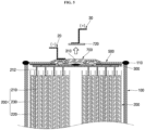
- FIG. 4 illustrates a schematic cross-sectional view of an electrical connection relationship in the cylindrical secondary battery illustrated in FIG. 1 .
- FIG. 5 illustrates a cross-sectional view the fusible link separated from the cylindrical secondary battery illustrated in FIG. 4 .
- an external positive terminal 30 may be connected to the head 720 of the first terminal 700, and an external negative terminal 20 may be connected to the cap plate 500. If a high current exceeding a limit (or maximum) current is generated due to an external short circuit or heat generation, Referring to FIG. 5 , resistance in the fusible link 730, which has a diameter less than that of the head 720 or of the base block 710, may significantly increase causing the fusible link 730 to melt and, thus, disconnect from the base block 710. In some embodiments, the external positive terminal 30 and the head 720 of the first terminal 700 may be separated from the base block 710 to cut off current. In some embodiments, the fusible link 730 may act as a fuse to cut off the current.
- the insulation member 740 may be very resistant to high heat, and thus, even if the head 720 is detached and separated, the base block 710 and the cap plate 500 may remain insulated from each other and sealed therebetween, referring to FIG. 5 . This is achieved because the insulation member 740 is filled in the space in which the protruding and recessed structures of the cap plate 500 and the first terminal 700 are alternately disposed. Therefore, the sealing and insulation of the cylindrical secondary battery 10 may be secured even if the high current is generated and the current is cut off, and thus, safety may be maintained.
- the secondary battery according to embodiments of the present disclosure may further include a structure for preventing the external short circuit.
- FIGS. 6 and 7 illustrate enlarged cross-sectional views of a cap plate and a first terminal according to other embodiments.
- a surface of a second plate part 530' may protrude further outwardly than (e.g., may protrude above) the surface of the head 720 of the first terminal 700.
- a surface height of the second plate part 530' may be higher than a surface height of the head 720.
- a thickness of the second plate part 530' may be greater than that of a first plate part 510 or an inclined part 520.
- a protrusion 742' that protrudes further outwardly than (e.g., protrudes above) the surface of the head 720 of the first terminal 700' may be disposed on a top surface of an insulation member 740' (e.g., the surface exposed between the first plate part 510 and the head 720).
- the first terminal and the cap plate may not be short circuited together.
- limitations such as short circuit marks, voltage drop, damage, poor outer appearance, leakage, and the like may be prevented from occurring.
- the rivet terminal structure may be improved to cut off the current if the high current is generated, thereby improving the safety of the secondary battery.
Landscapes
- Chemical & Material Sciences (AREA)
- Chemical Kinetics & Catalysis (AREA)
- Electrochemistry (AREA)
- General Chemical & Material Sciences (AREA)
- Inorganic Chemistry (AREA)
- Engineering & Computer Science (AREA)
- Manufacturing & Machinery (AREA)
- Connection Of Batteries Or Terminals (AREA)
- Sealing Battery Cases Or Jackets (AREA)
Abstract
Description
- Aspects of embodiments of the present disclosure relate to a cylindrical secondary battery.
- Generally, a cylindrical secondary battery has an electrode assembly wound in a cylindrical shape accommodated together with an electrolyte in a cylindrical can, which is then sealed with a cap plate. The cap plate may be provided with a cap-up or a rivet terminal as a structure acting as a positive terminal.
- The rivet terminal is thicker than the cap-up structure because it requires physical coupling strength to maintain a compressive force on a gasket. In addition, because soldering bonding is structurally impossible, a fusible link which allows for current to be cut off by being melted by high current is not feasible.
- The above-described information serves as background to the present disclosure and is for improving understanding of the background of the present disclosure. Thus, it may include information that does not constitute the related (or prior) art.
- Aspects of embodiments of the present disclosure provide a cylindrical secondary battery having a current blocking function.
- A cylindrical secondary battery, according to an embodiment of the present disclosure, includes: a cylindrical can; a cap plate coupled to the can, the cap plate having a convex area, a concave area, and an opening; an electrode assembly accommodated in the can and including a first electrode plate and a second electrode plate; and a first terminal exposed to the outside of the cap plate through the opening and having a convex area and a concave area. The convex areas and the concave areas of the cap plate and the first terminal are alternately arranged.
- The first terminal may include: a base block electrically connected to the first electrode plate; a head facing the base block and exposed to the outside through the opening; and a fusible link connecting the base block and the head and having a diameter less than that of the head.
- The base block may include: a first protrusion protruding from an edge of a top surface thereof toward the head; a second protrusion protruding from a center thereof toward the head; and a groove recessed between the first protrusion and the second protrusion.
- The cap plate may include: a flat first plate part; a second plate part parallel to the first plate part; an inclined part inclined upwardly from the first plate part and extending between the first plate part and the second plate part; and an extension part extending from the second plate part toward the base block.
- The second plate part and the first protrusion may face each other, and the extension part and the groove may face each other.
- The first terminal may further include an insulation member between the base block and the head.
- The insulation member may be a glass to metal sealing material.
- The cylindrical secondary battery may further include: a first electrode collector plate electrically connected to the first electrode plate and the first terminal; and a second electrode collector plate electrically connected to the second electrode plate and the can.
- Opposite ends of the can may be open. The cap plate may be coupled to one open end, and a circular bottom plate may be coupled to the other open end.
- The first electrode collector plate may be between the electrode assembly and the cap plate, and the second electrode collector plate may be between the electrode assembly and the bottom plate.
- A surface of the second plate part may protrude further outwardly than a surface of the head.
- The insulation member may include a protrusion protruding further outwardly than a surface of the head.
- At least some of the above and other features of the invention are set out in the claims.
- The accompanying drawings are included to provide a further understanding of the present disclosure and are incorporated in and constitute a part of this specification. The drawings illustrate embodiments of the present disclosure and, together with the description, describe aspects and features of the present disclosure. In the drawings:
-
FIG. 1 illustrates a schematic cross-sectional view of a cylindrical secondary battery according to an embodiment; -
FIG. 2 illustrates an enlarged cross-sectional view of a cap plate and a first terminal of the cylindrical secondary battery shown inFIG. 1 ; -
FIG. 3 illustrates an enlarged cross-sectional view of a bottom plate of the cylindrical secondary battery shown inFIG. 1 ; -
FIG. 4 illustrates a schematic cross-sectional view of an electrical connection relationship in the cylindrical secondary battery shown inFIG. 1 ; -
FIG. 5 illustrates a cross-sectional view of a fusible link separated from the cylindrical secondary battery illustrated inFIG. 4 ; and -
FIGS. 6 and 7 illustrate enlarged cross-sectional views of a cap plate and a first terminal according to various embodiments. - Embodiments of the present disclosure may be embodied in many different forms and should not be construed as being limited to the embodiments described herein. Rather, these embodiments are provided so that this disclosure will be thorough and complete and will fully convey the scope of the present disclosure to those skilled in the art.
- It will be understood that when an element or layer is referred to as being "on," "connected to," or "coupled to" another element or layer, it may be directly on, connected, or coupled to the other element or layer or one or more intervening elements or layers may also be present. When an element or layer is referred to as being "directly on," "directly connected to," or "directly coupled to" another element or layer, there are no intervening elements or layers present. For example, when a first element is described as being "coupled" or "connected" to a second element, the first element may be directly coupled or connected to the second element or the first element may be indirectly coupled or connected to the second element via one or more intervening elements.
- In the figures, dimensions of the various elements, layers, etc. may be exaggerated for clarity of illustration. The same reference numerals designate the same elements. As used herein, the term "and/or" includes any and all combinations of one or more of the associated listed items. Further, the use of "may" when describing embodiments of the present disclosure relates to "one or more embodiments of the present disclosure." Expressions, such as "at least one of" and "any one of," when preceding a list of elements, modify the entire list of elements and do not modify the individual elements of the list. For example, the expression "at least one of a, b, or c" indicates only a, only b, only c, both a and b, both a and c, both b and c, all of a, b, and c, or variations thereof. As used herein, the terms "use," "using," and "used" may be considered synonymous with the terms "utilize," "utilizing," and "utilized," respectively. As used herein, the terms "substantially," "about," and similar terms are used as terms of approximation and not as terms of degree, and are intended to account for the inherent variations in measured or calculated values that would be recognized by those of ordinary skill in the art.
- It will be understood that, although the terms first, second, third, etc. may be used herein to describe various elements, components, regions, layers, and/or sections, these elements, components, regions, layers, and/or sections should not be limited by these terms. These terms are used to distinguish one element, component, region, layer, or section from another element, component, region, layer, or section. Thus, a first element, component, region, layer, or section discussed below could be termed a second element, component, region, layer, or section without departing from the teachings of example embodiments.
- Spatially relative terms, such as "beneath," "below," "lower," "above," "upper," and the like, may be used herein for ease of description to describe one element or feature's relationship to another element(s) or feature(s) referring to the figures. It will be understood that the spatially relative terms are intended to encompass different orientations of the device in use or operation in addition to the orientation depicted in the figures. For example, if the device in the figures is turned over, elements described as "below" or "beneath" other elements or features would then be oriented "above" or "over" the other elements or features. Thus, the term "below" may encompass both an orientation of above and below. The device may be otherwise oriented (rotated 90 degrees or at other orientations), and the spatially relative descriptors used herein should be interpreted accordingly.
- The terminology used herein is for the purpose of describing embodiments of the present disclosure and is not intended to be limiting of the present disclosure. As used herein, the singular forms "a" and "an" are intended to include the plural forms as well, unless the context clearly indicates otherwise. It will be further understood that the terms "includes," "including," "comprises," and/or "comprising," when used in this specification, specify the presence of stated features, integers, steps, operations, elements, and/or components but do not preclude the presence or addition of one or more other features, integers, steps, operations, elements, components, and/or groups thereof.
- Hereinafter, a cylindrical secondary battery according to embodiments of the present disclosure will be described, in detail, with reference to the accompanying drawings. For convenience, an upper side is defined as an upper portion, and a lower side is defined as a lower portion based on the orientation of
FIG. 1 . -
FIG. 1 is a schematic cross-sectional view of a cylindrical secondary battery according to an embodiment.FIG. 2 illustrates an enlarged cross-sectional view of a cap plate and a first terminal of the cylindrical secondary battery shown inFIG. 1 .FIG. 3 illustrates an enlarged cross-sectional view of a bottom plate the cylindrical secondary battery shown inFIG. 1 . - Referring to
FIG. 1 , a cylindricalsecondary battery 10, according to an embodiment of the present disclosure, may include acylindrical can 100, acap plate 500 coupled to one end of thecan 100, and abottom plate 600 coupled to another end (e.g., an opposite end) of thecan 100. Theelectrode assembly 200 may be accommodated together with an electrolyte in thecan 100. Theelectrode assembly 200 may be electrically connected to a firstelectrode collector plate 300 and a secondelectrode collector plate 400 and may be electrically connected to afirst terminal 700 and thecan 100. After thecan 100 and thebottom plate 600 are assembled together, theelectrode assembly 200, connected to the firstelectrode collector plate 300 and the secondelectrode collector plate 400, may be accommodated in thecan 100, and thecap plate 500 may be assembled to seal thecan 100. - Referring to
FIG. 1 , thecan 100 may have a hollow cylindrical shape, and at least one of one end or the other end of thecan 100 in a longitudinal direction may be open. If one end of the can is open, a circular bottom part of the can and a side part extending from the bottom part may be integrated with each other. If both ends of thecan 100 are open, thecircular bottom plate 600 may be separately coupled to thecan 100, as described above. The can 100 may be made of steel, a steel alloy, nickel-plated steel, a nickel-plated steel alloy, aluminium, an aluminium alloy, or an equivalent thereof but is not limited thereto. - Referring to
FIG. 1 , theelectrode assembly 200 may include afirst electrode plate 210, asecond electrode plate 220, and aseparator 230. For example, thefirst electrode plate 210 may be a positive electrode plate on which a positive electrode active material layer (e.g., transition metal oxide (LiCoO2, LiNiO2, LiMn2O4, etc.)) is disposed on both surfaces thereof. Thefirst electrode plate 210 may have a firstelectrode non-coating portion 212 on which the positive electrode active material layer is not disposed. The firstelectrode non-coating portion 212 may be disposed to face an upper portion of thecan 100, which is one end of thecan 100, with respect toFIG. 1 . In some embodiments, thesecond electrode plate 220 may be a negative electrode plate on which a negative electrode active material layer (e.g., graphite, carbon, etc.) is disposed on both surfaces thereof. Thesecond electrode plate 220 may include a secondelectrode non-coating portion 222 on which the negative electrode active material layer is not disposed. The secondelectrode non-coating portion 222 may be disposed to face a lower portion of thecan 100, which is the other end of thecan 100, with respect toFIG. 1 . In some embodiments, theseparator 230 may be interposed between thefirst electrode plate 210 and thesecond electrode plate 220 to prevent a short circuit therebetween while allowing only lithium ions to move therebetween. For example, thefirst electrode plate 210 may be aluminium (Al) foil, thesecond electrode plate 220 may be copper (Cu) or nickel (Ni) foil, and theseparator 230 may be made of polyethylene (PE) or polypropylene (PP), but the present disclosure is not limited to these materials. Thefirst electrode plate 210, thesecond electrode plate 220, and theseparator 230 may be wound in a substantially cylindrical shape and accommodated in thecan 100. Here, the firstelectrode non-coating portion 212 may be electrically connected to the firstelectrode collector plate 300, and the secondelectrode non-coating portion 222 may be electrically connected to the secondelectrode collector plate 400. - Referring to
FIG. 1 , the firstelectrode collector plate 300 may be disposed between the firstelectrode non-coating portion 212 and thecap plate 500 and electrically connected to the firstelectrode non-coating portion 212. Aninsulator 305 may be inserted between the firstelectrode collector plate 300 and thecap plate 500. The firstelectrode collector plate 300 may be electrically connected to afirst terminal 700, to be described later, by welding (welding part 310). Because the firstelectrode non-coating portion 212 and thefirst terminal 700 are electrically connected to each other, thefirst terminal 700 may be a positive electrode. - The second
electrode collector plate 400 may be disposed between the secondelectrode non-coating portion 222 and thebottom plate 600 and electrically connected to the secondelectrode non-coating portion 222. The secondelectrode collector plate 400 may be in contact with or welded to thebottom plate 600 or thecan 100 and, thus, may be electrically connected to thebottom plate 600 or thecan 100. Aninsulator 410 may be inserted between the secondelectrode collector plate 400 and thebottom plate 600 to insulate an area other than a portion that is in contact with thebottom plate 600 or thecan 100. Because the secondelectrode non-coating portion 222 and thecan 100 are electrically connected to each other, thecan 100 may be a negative electrode. - Referring to
FIGS. 1 and2 , thecap plate 500 may have a substantially circular plate shape when viewed from above and may be welded to thecan 100 to seal thecan 100. Thecap plate 500 may be made of aluminium or the same material as thecan 100. Thecap plate 500 may have a circular plate ring shape having a hollow (e.g., an opening) at a center thereof. Thebottom plate 600 may be coupled to the lower portion of thecan 100 facing (e.g., opposite to) thecap plate 500. - In some embodiments, the
cap plate 500 may include afirst plate part 510 parallel to the firstelectrode collector plate 300, aninclined part 520 connected to thefirst plate part 510 and inclined upwardly from thefirst plate part 510, asecond plate part 530 connected to theinclined part 520 and parallel to thefirst plate part 510, and anextension part 540 vertically extending downwardly from thesecond plate part 530. - The
cap plate 500 may have aprotrusion 512 protruding upwardly along an edge of thefirst plate part 510. Theprotrusion 512 may be a portion to be welded to thecan 100 and may form awelding part 110 seated on thecan 100 and melted during laser welding to weld thecap plate 500 to thecan 100. Because thefirst plate part 510 is welded to thecan 100, thefirst plate part 510 may have the same negative polarity as thecan 100. - The
inclined part 520 may extend upwardly to form an obtuse angle with respect to thefirst plate part 510. - The
second plate part 530 may have an area less than that of thefirst plate part 510. One end of thesecond plate part 530 may be connected to theinclined part 520, and another end thereof may be disposed toward the hollow at the center of thecap plate 500. The end of thesecond plate part 530 toward the hollow may be bent downwardly to form theextension part 540. Thefirst terminal 700 may be disposed below thesecond plate part 530 and theextension part 540. - Referring to
FIG. 3 , thebottom plate 600 may have a substantially circular plate shape when viewed from below and may be coupled to the lower portion of thecan 100 to seal thecan 100. Anotch 610 that is configured to rupture if gas pressure inside thecan 100 exceeds a reference (or predetermined) pressure may be formed in a plate surface (e.g., an inner plate surface) of thebottom plate 600. Theprotrusion 620 may protrude downwardly along an edge of thebottom plate 600. Theprotrusion 620 may be welded to thecan 100 to form a weldedpart 110. - Referring to
FIGS. 1 and2 , the above-described first terminal 700 may include abase block 710 electrically connected to the firstelectrode collector plate 300, ahead 720 electrically connected to the outside, afusible link 730 connecting thebase block 710 to thehead 720, and aninsulation member 740 insulating the first terminal 700 from thecap plate 500. In some embodiments, thebase block 710, thehead 720, and thefusible link 730 may be made of aluminium. - The
base block 710 may have a circular plate shape when viewed from the bottom and may have a flat bottom surface and a top surface with an uneven structure. The bottom surface of thebase block 710 may be electrically connected to the firstelectrode collector plate 300 by welding or the like (formation of a weld part 310). In some embodiments, thebase block 710 may include afirst protrusion 712 protruding upwardly along an edge of the top surface of thebase block 710 and asecond protrusion 714 protruding upwardly at the center thereof. Thebase block 710 may have agroove 716 defined therein and recessed downwardly between thefirst protrusion 712 and thesecond protrusion 714. A height from the bottom surface of thebase block 710 to the top surface of thefirst protrusion 712 may be greater than a height from the bottom surface of thebase block 710 to the top surface of the second protrusion 714 (e.g., thefirst protrusion 712 may be thicker than the second protrusion 714). A height from the bottom surface of thebase block 710 to the top surface of thegroove 716 may be less than a height from the bottom surface of thebase block 710 to the top surface of thesecond protrusion 714 such that thefirst protrusion 712 is disposed below thesecond plate part 530. Thegroove 716 is defined below theextension part 540. Due to this arrangement, the protruding portion of thefirst terminal 700 may be disposed on the protruding portion of thecap plate 500, and the protruding portion of thecap plate 500 may be disposed on the recessed portion of thefirst terminal 700. In some embodiments, thecap plate 500 and thefirst terminal 700 may be disposed in a structure in which thecap plate 500 and thefirst terminal 700 are alternately engaged with each other. Thehead 720 may be disposed to be spaced a distance (e.g., a predetermined distance) from (or above) the top surface of thesecond protrusion 714. - The
head 720 may be a portion electrically connected to the outside and may be electrically connected to thebase block 710 by thefusible link 730. Therefore, thehead 720 has a positive polarity. In some embodiments, thehead 720 may have a circular plate shape. A top surface of thehead 720 may protrude from the top surface of thesecond plate part 530 of thecap plate 500 or may be disposed at the same height as the top surface of thesecond plate part 530 of thecap plate 500. - The
fusible link 730 may mechanically and electrically connect thebase block 710 to thehead 720. Thefusible link 730 may have a diameter less than a diameter of thehead 720 and may have an hourglass shape. In some embodiments, thebase block 710 and thehead 720 may be soldered to each other to act as thefusible link 730. In some embodiments, because thefusible link 730 has a diameter less than that of thehead 720, a shape of thefusible link 730 may not be limited as long as thefusible link 730 is melted if high current passes therethrough. - The
insulation member 740 may be made of, for example, a glass to metal sealing (GTMS) material or a polymer material. Theinsulation member 740 may insulate thecap plate 500 from thefirst terminal 700 by filling the space between thebase block 710 and thehead 720 and may seal the inside of thecan 100. - In an embodiment in which the
insulation member 740 is made of the GTMS material, theinsulation member 740 may be prepared in a manner in which a binder is mixed with glass powder, and then, the mixture is pressed and molded into a desired shape. Then, thecap plate 500 and thefirst terminal 700 are disposed on and integrated with the mixture in a sintering process. In an embodiment in which theinsulation member 740 is made of the polymer material, theinsulation member 740 may be manufactured to be thicker than a gap between thecap plate 500 and thebase block 710 and then disposed under thecap plate 500. Then, thefirst terminal 700 may be bonded to be in close contact with thecap plate 500 and thebase block 710 through heat treatment. - In the cylindrical secondary battery according to embodiments of the present disclosure having the above-described structure, operation of the fusible link and a state of the secondary battery when a high current is generated will be described hereinafter.
-
FIG. 4 illustrates a schematic cross-sectional view of an electrical connection relationship in the cylindrical secondary battery illustrated inFIG. 1 .FIG. 5 illustrates a cross-sectional view the fusible link separated from the cylindrical secondary battery illustrated inFIG. 4 . - Referring to
FIG. 4 , in the cylindricalsecondary battery 10 as described above, an externalpositive terminal 30 may be connected to thehead 720 of thefirst terminal 700, and an externalnegative terminal 20 may be connected to thecap plate 500. If a high current exceeding a limit (or maximum) current is generated due to an external short circuit or heat generation, Referring toFIG. 5 , resistance in thefusible link 730, which has a diameter less than that of thehead 720 or of thebase block 710, may significantly increase causing thefusible link 730 to melt and, thus, disconnect from thebase block 710. In some embodiments, the externalpositive terminal 30 and thehead 720 of thefirst terminal 700 may be separated from thebase block 710 to cut off current. In some embodiments, thefusible link 730 may act as a fuse to cut off the current. - In an embodiment in which the
insulation member 740 is made of the GTMS material, theinsulation member 740 may be very resistant to high heat, and thus, even if thehead 720 is detached and separated, thebase block 710 and thecap plate 500 may remain insulated from each other and sealed therebetween, referring toFIG. 5 . This is achieved because theinsulation member 740 is filled in the space in which the protruding and recessed structures of thecap plate 500 and thefirst terminal 700 are alternately disposed. Therefore, the sealing and insulation of the cylindricalsecondary battery 10 may be secured even if the high current is generated and the current is cut off, and thus, safety may be maintained. - The secondary battery according to embodiments of the present disclosure may further include a structure for preventing the external short circuit.
-
FIGS. 6 and 7 illustrate enlarged cross-sectional views of a cap plate and a first terminal according to other embodiments. - In another embodiment, Referring to
FIG. 6 , in a cap plate 500', a surface of a second plate part 530' (e.g., the top surface with reference toFIG. 6 ) may protrude further outwardly than (e.g., may protrude above) the surface of thehead 720 of thefirst terminal 700. In some embodiments, inFIG. 6 , a surface height of the second plate part 530' may be higher than a surface height of thehead 720. For this, a thickness of the second plate part 530' may be greater than that of afirst plate part 510 or aninclined part 520. - In another embodiment, for example, referring to
FIG. 7 , a protrusion 742' that protrudes further outwardly than (e.g., protrudes above) the surface of thehead 720 of the first terminal 700' may be disposed on a top surface of an insulation member 740' (e.g., the surface exposed between thefirst plate part 510 and the head 720). - Due to the structure illustrated in
FIG. 6 or 7 , even if a linear metal object contacts the outside of the secondary battery, the first terminal and the cap plate may not be short circuited together. In some embodiments, limitations such as short circuit marks, voltage drop, damage, poor outer appearance, leakage, and the like may be prevented from occurring. - According to embodiments of the present disclosure, the rivet terminal structure may be improved to cut off the current if the high current is generated, thereby improving the safety of the secondary battery.
- The above-described embodiments are merely some embodiments, and the present disclosure is not limited to the foregoing embodiments. It will be understood by those of ordinary skill in the art that various changes in form and details may be made therein without departing from the scope of the present disclosure as defined by the following claims and their equivalents.
Claims (12)
- A cylindrical secondary battery comprising:a cylindrical can;a cap plate coupled to the can, the cap plate having a convex area, a concave area, and an opening;an electrode assembly accommodated in the can and comprising a first electrode plate and a second electrode plate; anda first terminal exposed to the outside of the cap plate through the opening and having a convex area and a concave area,wherein the convex areas and the concave areas of the cap plate and the first terminal are alternately arranged.
- The cylindrical secondary battery as claimed in claim 1, wherein the first terminal comprises:a base block electrically connected to the first electrode plate;a head facing the base block and exposed to the outside through the opening;
anda fusible link connecting the base block and the head and having a diameter less than that of the head. - The cylindrical secondary battery as claimed in claim 2, wherein the base block comprises:a first protrusion protruding from an edge of a top surface thereof toward the head;a second protrusion protruding from a center thereof toward the head; anda groove recessed between the first protrusion and the second protrusion.
- The cylindrical secondary battery as claimed in claim 3, wherein the cap plate comprises:a flat first plate part;a second plate part parallel to the first plate part;an inclined part inclined upwardly from the first plate part and extending between the first plate part and the second plate part; andan extension part extending from the second plate part toward the base block.
- The cylindrical secondary battery as claimed in claim 4, wherein the second plate part and the first protrusion face each other, and
wherein the extension part and the groove face each other. - The cylindrical secondary battery as claimed in any one of claims 2 to 5, wherein the first terminal further comprises an insulation member between the base block and the head.
- The cylindrical secondary battery as claimed in claim 6, wherein the insulation member is a glass to metal sealing material.
- The cylindrical secondary battery as claimed in any one of claims 1 to 7, further comprising:a first electrode collector plate electrically connected to the first electrode plate
and the first terminal; anda second electrode collector plate electrically connected to the second electrode plate and the can. - The cylindrical secondary battery as claimed in claim 8, wherein opposite ends of the can are open, and
wherein the cap plate is coupled to one open end, and a circular bottom plate is coupled to the other open end. - The cylindrical secondary battery as claimed in claim 9, wherein the first electrode collector plate is between the electrode assembly and the cap plate, and
wherein the second electrode collector plate is between the electrode assembly and the bottom plate. - The cylindrical secondary battery as claimed in any one of claims 4 to 10, wherein a surface of the second plate part protrudes further outwardly than a surface of the head.
- The cylindrical secondary battery as claimed in any one of claims 6 to 10, wherein the insulation member comprises a protrusion protruding further outwardly than a surface of the head.
Applications Claiming Priority (1)
| Application Number | Priority Date | Filing Date | Title |
|---|---|---|---|
| KR1020220126938A KR102554328B1 (en) | 2022-10-05 | 2022-10-05 | Cylindrical secondary battery |
Publications (2)
| Publication Number | Publication Date |
|---|---|
| EP4350850A2 true EP4350850A2 (en) | 2024-04-10 |
| EP4350850A3 EP4350850A3 (en) | 2024-05-22 |
Family
ID=87160021
Family Applications (1)
| Application Number | Title | Priority Date | Filing Date |
|---|---|---|---|
| EP23200525.6A Pending EP4350850A3 (en) | 2022-10-05 | 2023-09-28 | Cylindrical secondary battery |
Country Status (4)
| Country | Link |
|---|---|
| US (1) | US20240120585A1 (en) |
| EP (1) | EP4350850A3 (en) |
| KR (1) | KR102554328B1 (en) |
| CN (1) | CN117855712A (en) |
Cited By (1)
| Publication number | Priority date | Publication date | Assignee | Title |
|---|---|---|---|---|
| US20240413503A1 (en) * | 2023-06-09 | 2024-12-12 | Samsung Sdi Co., Ltd. | Secondary battery |
Families Citing this family (1)
| Publication number | Priority date | Publication date | Assignee | Title |
|---|---|---|---|---|
| KR20250143583A (en) * | 2024-03-25 | 2025-10-02 | 삼성에스디아이 주식회사 | Rechargeable battery |
Family Cites Families (8)
| Publication number | Priority date | Publication date | Assignee | Title |
|---|---|---|---|---|
| KR100280721B1 (en) * | 1998-11-28 | 2001-03-02 | 김순택 | Cap assembly of square secondary battery |
| EP1914818B1 (en) * | 2006-10-06 | 2013-07-24 | Greatbatch Ltd. | Highly compact electrochemical cell |
| KR20170044973A (en) * | 2015-10-16 | 2017-04-26 | 주식회사 엘지화학 | Secondary battery |
| KR102487217B1 (en) * | 2018-02-01 | 2023-01-11 | 주식회사 엘지에너지솔루션 | Cap Assembly Having Rivet, and Cylindrical Battery Comprising Beading-part free and Climping-part free and the Cap Assembly |
| KR102642157B1 (en) * | 2018-04-30 | 2024-03-04 | 삼성에스디아이 주식회사 | Cylindrical lithium ion secondary battery |
| CN115004461B (en) * | 2020-02-28 | 2024-08-20 | 松下知识产权经营株式会社 | Power storage equipment |
| KR20220118893A (en) * | 2021-02-19 | 2022-08-26 | 주식회사 엘지에너지솔루션 | Cylindrical secondary battery cell, and battery pack and vehicle including the same |
| CN215578778U (en) * | 2021-05-21 | 2022-01-18 | 湖北亿纬动力有限公司 | A new type of cylindrical battery |
-
2022
- 2022-10-05 KR KR1020220126938A patent/KR102554328B1/en active Active
-
2023
- 2023-08-21 US US18/453,058 patent/US20240120585A1/en active Pending
- 2023-09-28 CN CN202311278805.8A patent/CN117855712A/en active Pending
- 2023-09-28 EP EP23200525.6A patent/EP4350850A3/en active Pending
Cited By (1)
| Publication number | Priority date | Publication date | Assignee | Title |
|---|---|---|---|---|
| US20240413503A1 (en) * | 2023-06-09 | 2024-12-12 | Samsung Sdi Co., Ltd. | Secondary battery |
Also Published As
| Publication number | Publication date |
|---|---|
| EP4350850A3 (en) | 2024-05-22 |
| US20240120585A1 (en) | 2024-04-11 |
| KR102554328B1 (en) | 2023-07-11 |
| CN117855712A (en) | 2024-04-09 |
Similar Documents
| Publication | Publication Date | Title |
|---|---|---|
| US20240120626A1 (en) | Cylindrical secondary battery | |
| EP4362154A1 (en) | Cylindrical secondary battery | |
| EP4148879A1 (en) | Cylindrical secondary battery | |
| KR100978092B1 (en) | Cap assembly and secondary battery having the same | |
| JP4231834B2 (en) | Secondary battery | |
| US10490792B2 (en) | Cap assembly for secondary battery | |
| KR102670692B1 (en) | Cylindrical secondary battery | |
| EP4258434A1 (en) | Cylindrical secondary battery | |
| KR101093339B1 (en) | High power secondary battery | |
| EP4350850A2 (en) | Cylindrical secondary battery | |
| EP4216363A1 (en) | Cylindrical secondary battery | |
| KR102611657B1 (en) | Secondary Battery | |
| EP1659651B1 (en) | Can-type secondary battery and method of manufacturing the same | |
| JP2011077023A (en) | Current breaking element, and secondary battery equipped with the same | |
| US8673483B2 (en) | Sealed battery | |
| US12407047B2 (en) | Battery and method of manufacturing same | |
| EP1973182A1 (en) | Secondary batery | |
| US20010012582A1 (en) | Prismatic sealed battery and method for making the same | |
| KR20260002386A (en) | Secondary Battery | |
| KR102824566B1 (en) | Cylindrical secondary battery | |
| EP4362153A1 (en) | Secondary battery | |
| KR102754588B1 (en) | Top cap, cap assembly for including the same and secondary battery | |
| KR20120052035A (en) | Cap assembly for secondary battery, secondary battery using the same, and method for manufacturing the secondary battery | |
| KR100490547B1 (en) | Lithium secondary battery having a protective mean | |
| KR101810269B1 (en) | The secondary battery with increased bonding strength between electrode assembly and the battery case |
Legal Events
| Date | Code | Title | Description |
|---|---|---|---|
| PUAI | Public reference made under article 153(3) epc to a published international application that has entered the european phase |
Free format text: ORIGINAL CODE: 0009012 |
|
| STAA | Information on the status of an ep patent application or granted ep patent |
Free format text: STATUS: REQUEST FOR EXAMINATION WAS MADE |
|
| 17P | Request for examination filed |
Effective date: 20230928 |
|
| AK | Designated contracting states |
Kind code of ref document: A2 Designated state(s): AL AT BE BG CH CY CZ DE DK EE ES FI FR GB GR HR HU IE IS IT LI LT LU LV MC ME MK MT NL NO PL PT RO RS SE SI SK SM TR |
|
| PUAL | Search report despatched |
Free format text: ORIGINAL CODE: 0009013 |
|
| AK | Designated contracting states |
Kind code of ref document: A3 Designated state(s): AL AT BE BG CH CY CZ DE DK EE ES FI FR GB GR HR HU IE IS IT LI LT LU LV MC ME MK MT NL NO PL PT RO RS SE SI SK SM TR |
|
| RIC1 | Information provided on ipc code assigned before grant |
Ipc: H01M 50/593 20210101ALI20240412BHEP Ipc: H01M 50/583 20210101ALI20240412BHEP Ipc: H01M 50/566 20210101ALI20240412BHEP Ipc: H01M 50/559 20210101ALI20240412BHEP Ipc: H01M 50/55 20210101ALI20240412BHEP Ipc: H01M 50/538 20210101ALI20240412BHEP Ipc: H01M 50/486 20210101ALI20240412BHEP Ipc: H01M 50/483 20210101ALI20240412BHEP Ipc: H01M 50/477 20210101ALI20240412BHEP Ipc: H01M 50/474 20210101ALI20240412BHEP Ipc: H01M 50/342 20210101ALI20240412BHEP Ipc: H01M 50/159 20210101ALI20240412BHEP Ipc: H01M 50/148 20210101ALI20240412BHEP Ipc: H01M 50/152 20210101ALI20240412BHEP Ipc: H01M 50/119 20210101ALI20240412BHEP Ipc: H01M 50/107 20210101AFI20240412BHEP |