EP4350844A1 - An assembly comprising a plurality of electrochemical cells and an electrical device comprising such assembly - Google Patents
An assembly comprising a plurality of electrochemical cells and an electrical device comprising such assembly Download PDFInfo
- Publication number
- EP4350844A1 EP4350844A1 EP22306489.0A EP22306489A EP4350844A1 EP 4350844 A1 EP4350844 A1 EP 4350844A1 EP 22306489 A EP22306489 A EP 22306489A EP 4350844 A1 EP4350844 A1 EP 4350844A1
- Authority
- EP
- European Patent Office
- Prior art keywords
- end group
- insulating layers
- group
- assembly
- thermal
- Prior art date
- Legal status (The legal status is an assumption and is not a legal conclusion. Google has not performed a legal analysis and makes no representation as to the accuracy of the status listed.)
- Pending
Links
Images

Classifications
-
- H—ELECTRICITY
- H01—ELECTRIC ELEMENTS
- H01M—PROCESSES OR MEANS, e.g. BATTERIES, FOR THE DIRECT CONVERSION OF CHEMICAL ENERGY INTO ELECTRICAL ENERGY
- H01M10/00—Secondary cells; Manufacture thereof
- H01M10/60—Heating or cooling; Temperature control
- H01M10/65—Means for temperature control structurally associated with the cells
- H01M10/653—Means for temperature control structurally associated with the cells characterised by electrically insulating or thermally conductive materials
-
- H—ELECTRICITY
- H01—ELECTRIC ELEMENTS
- H01M—PROCESSES OR MEANS, e.g. BATTERIES, FOR THE DIRECT CONVERSION OF CHEMICAL ENERGY INTO ELECTRICAL ENERGY
- H01M10/00—Secondary cells; Manufacture thereof
- H01M10/60—Heating or cooling; Temperature control
- H01M10/65—Means for temperature control structurally associated with the cells
- H01M10/655—Solid structures for heat exchange or heat conduction
- H01M10/6554—Rods or plates
- H01M10/6555—Rods or plates arranged between the cells
-
- H—ELECTRICITY
- H01—ELECTRIC ELEMENTS
- H01M—PROCESSES OR MEANS, e.g. BATTERIES, FOR THE DIRECT CONVERSION OF CHEMICAL ENERGY INTO ELECTRICAL ENERGY
- H01M10/00—Secondary cells; Manufacture thereof
- H01M10/60—Heating or cooling; Temperature control
- H01M10/65—Means for temperature control structurally associated with the cells
- H01M10/659—Means for temperature control structurally associated with the cells by heat storage or buffering, e.g. heat capacity or liquid-solid phase changes or transition
Definitions
- the present invention relates to an assembly comprising a plurality of electrochemical cells.
- the invention applies in particular to the manufacturing of a battery, especially for an electric or a hybrid vehicle.
- battery is meant a plurality of electrochemical cells electrically connected to one another.
- the plurality of electrochemical cells is arranged in the form of one or more module(s), each module comprising a plurality of electrochemical cells electrically connected to one another and mechanically assembled to one another by an assembly system, such as assembly plates.
- An electrochemical cell comprises, in particular, a group of positive electrodes connected to each other and a group of negative electrodes connected to each other, separated by a separator, the combination being known as a "stack".
- the positive electrodes connected to each other form a positive terminal
- the negative electrodes connected to each other form a negative terminal.
- Such layers are for example made of a thermally insulating material.
- the insulating layers placed between the electrochemical cells of a battery are identical to each other.
- One aim of the invention is thus to provide a solution preventing thermal runway in neighboring battery cells at any point of the battery in an efficient and economical way.
- the invention proposes an assembly comprising:
- the plurality of insulating layers consisting of a first end group of insulating layers, a central group of insulating layers and a second end group of insulating layers, the first end group, the central group and the second end group being successive and arranged in that particular order along the transverse direction.
- the arithmetical mean of thermal resistances of the first end group and the arithmetical mean of thermal resistances of the second end group are higher than the arithmetical mean of thermal resistances of the central group.
- the assembly comprises one or several of following features, taken individually or in any technically feasible combination:
- the invention also relates to an electrical device such as a battery module or a battery, comprising at least one assembly as previously described.
- the electrical device 10 is only partially depicted in Figure 1 and is for example a battery, a battery pack, or a battery module intended to be assembled with other modules in order to form a battery.
- the electrical device 10 is for example intended to be installed in an electric or hybrid motor vehicle (not shown).
- the electrical device 10 defines a longitudinal direction X that is for example the direction of travel of the vehicle, and a transverse direction Y perpendicular to the longitudinal direction X and which is for example the transverse direction of the vehicle.
- a third direction Z is further defined which is perpendicular to the longitudinal direction X and the transverse direction Y, and which is for example intended to be substantially vertical when the vehicle is on a horizontal surface (not shown).
- the electrical device 10 comprises at least one assembly 12, the assembly 12 comprising a first end 14 and second end 16 opposed to each other along the transverse direction Y and further comprising a first side 18 and a second side 20 opposed to each other along the longitudinal direction X.
- the electrical device 10 preferably comprises a plurality of assembly 12 electrically and mechanically connected to each other.
- the electrical device 10 preferably comprises, for each assembly 12, two side plates 22 and two end plates 24.
- each of the two side plates 22 lies against one of the first side 18 and the second side 20 of the assembly 12, and preferably covers it entirely.
- Each of the two end plates 24 lies against one of a first end 14 and second end 16 of the assembly 12, and preferably covers it entirely.
- the assembly 12 comprises a plurality of electrochemical cells 26 arranged along the transverse direction Y, especially between the two end plates 24.
- the assembly 12 preferably comprises at least four electrochemical cells 26.
- the assembly 12 comprises eight electrochemical cells 26.
- the assembly 12 comprises a plurality of insulating layers 28, each of the insulating layers 28 extending perpendicularly to the transverse direction Y, i.e. along the longitudinal direction X, and being arranged along the transverse direction Y between two adjacent electrochemical cells 26.
- the assembly 12 consists of a simple alternation of electrochemical cells 26 and insulating layers 28.
- the electrochemical cells 26 and the insulating layers 28 are arranged successively against each other in the transverse direction Y, so that there is no mechanical gap between these elements.
- the assembly 12 preferably comprises at least three insulating layers 28.
- the assembly 12 comprises a number of insulating layer 28 corresponding to the number of electrochemical cells 26 minus one.
- the assembly 12 comprises seven insulating layers 28.
- the insulating layers 28 is for example a plate, a foam or a gel of a thermal insulating material.
- the insulating layers 28 are made of a material selected from silicone, aerogel, fiberglass, Mica, and a phase-change material.
- the plurality of insulating layers 28 consists of a first end group 30 of insulating layers, a central group 32 of insulating layers and a second end 34 group of insulating layers.
- Each of the first end group 30, the central group 32 and the second end group 34 comprises at least one insulating layer 28.
- the first end group 30, the central group 32 and the second end group 34 are successive and arranged in that particular order along the transverse direction Y.
- the insulating layers 28 of the first end group 30 are nearest to the first end 14 of the assembly 12.
- the insulating layers 28 of the second end group 34 are nearest to the second end 16 of the assembly 12.
- the insulating layers 28 of central group 32 are located between the insulating layers 28 of the first end group 30 and the insulating layers 28 of the second end group 34 along the transverse direction Y.
- the first end group 30 and the second end group 34 have a same number of insulating layers 28.
- each of the first end group 30 and the second end group 34 is composed of two insulating layers 28, and the central group 34 is composed of three insulating layers 28.
- the first end group 30 and the second end group 34 are symmetrical to each other with respect to a median plane XZ of the assembly 12.
- the median plan XZ of the assembly 12 is a plane perpendicular to the transverse direction Y and is preferably at the same distance from each end 14, 16 of the assembly 12.
- Each of the insulating layers 28 has a thermal resistance r th along the transverse direction Y.
- This thermal resistance r th quantifies the surface resistance to a heat flow along the transverse direction Y between two isotherms.
- the two isotherms are preferably two plane surfaces of the insulating layer 28 parallel to each other, each lying against one of the corresponding electrochemical cells 26.
- each insulating layer 28 is defined in the transverse direction Y, and corresponds to the gap along the transverse direction Y between the two nearby electrochemical cells 26 as illustrated in Figure 2 .
- the arithmetical mean of thermal resistances r th of the first end group 30 and the arithmetical mean of thermal resistances r th of the second end group 34 are higher than the arithmetical mean of thermal resistances r th of the central group 32.
- the lowest thermal resistance r th in the first end group 30 and the lowest thermal resistance r th in the second end group 34 are at least 10% higher, preferably at least 50% higher, than the highest thermal resistance r th in the central group 32.
- the thermal resistances r th of the first end group 30 all have the same value +/- 5% and the thermal resistances r th of the second end group 34 all have the same value +/- 5%.
- the value of the thermal resistances r th of the first end group 30 is equal +/- 5% to the value of the thermal resistances r th of the second end group 34.
- the thermal resistances r th of the central group 32 all have the same value +/- 5%.
- the thermal conductivities ⁇ of the insulating layers 28 of the assembly 12 all have the same value +/- 5% and the variation of thermal resistances r th is obtained by a variation of thicknesses T of the insulating layers 28.
- the arithmetical mean of thicknesses T of the first end group 30 and the arithmetical mean of thicknesses T of the second end group 34 are larger than the arithmetical mean of the thicknesses T of the central group 32.
- the lowest thickness T in the first end group 30 and the lowest thickness T in the second end group 34 are at least 10% larger, preferably at least 50% larger, than the highest thickness T in the central group 32.
- the thicknesses T of the first end group 30 all have the same value +/- 5% and the thicknesses T of the second end group 34 all have the same value +/- 5%.
- the value of the thicknesses T of the first end group 30 is equal to the value of the thicknesses T of the second end group 34.
- the thicknesses T of the first end group 30 and the thicknesses T of the second end group 34 are comprised between 2 mm and 6 mm, preferably between 2.5 mm and 4.5 mm.
- the thicknesses T of the central group 32 all have the same value +/- 5%.
- the thicknesses T of the insulating layers 28 of the central group 32 are comprised between 0.1 mm and 4 mm, preferably between 0.5 mm and 3 mm.
- the thermal resistance required in the middle of the assembly 12 is actually smaller as the thermal resistance required near the ends 14, 16 of the assembly.
- the smaller thermal resistances r th of the central group 32 are sufficient to prevent, or at least delay, the thermal runaway propagating in both ways in the middle of the assembly 12.
- the higher thermal resistances r th of the first end group 30 and of the second end group 34 allow efficiently preventing, or at least delaying, the thermal runaway propagating in only one way.
- the assembly 12 according to the invention therefore allows preventing thermal runway in the electrical device 10 in an efficient way at any point of the battery.
- thermal resistance r th along the transverse direction Y, and in particular of the thickness T, of the insulating layers 28 allows optimizing the thermal insulation by adapting the thermal resistance r th according to the position along the transverse direction Y, and thus according to the required thermal insulation.
- this allows reducing the total length of the assembly 12 along the transverse direction Y by avoiding the use of too thick insulating layers 28.
- FIG. 3 an assembly 120 according to a second embodiment of the invention is described.
- the assembly 120 is analogous to the assembly 12 shown in Figures 1 and 2 . Similar elements have the same numerical references and will not be described again. Only the differences will be described in detail below.
- the thermal resistances r th of the first end group 30 do not all have the same value and the thermal resistances r th of the second end group 34 do not all have the same value.
- the thermal resistance r th of each of the insulating layers 28 of the first end group 30 and the thermal resistance r th of each of the insulating layers 28 of the second end group 34 increases as a function of the distance of said insulating layer 28 from the median plan XZ of the assembly 12.
- the thickness T of each of the insulating layers 28 of the first end group 30 and the thickness T of each of the insulating layers 28 of the second end group 34 increases as a function of the distance of the insulating layer 28 from the median plan XZ of the assembly 12.
- the thicknesses T of the first end group 30 and the thicknesses T of the second end group 34 increase with a constant step, for example equal to 0.5 mm.
- the thermal resistances r th of the central group 32 do not all have the same value.
- the thermal resistance r th of each of the insulating layers 28 of the central group 32 increases as a function of the distance of said insulating layer 28 from the median plan XZ of the assembly 12.
- the thickness T of each of the insulating layers 28 of the central group 32 increases as a function of the distance of said insulating layer 28 from the median plan XZ.
- the thicknesses T of the insulating layers 28 of the central group 32 increase with a constant step, for example equal to 0.5 mm.
- the thermal resistances r th of the first end group 30 all have the same value +/- 5% and the thermal resistances r th of the second end group 34 all have the same value +/- 5%.
- the thermal resistance r th of each of the insulating layers 28 of the central group 32 increases as a function of the distance of said insulating layer 28 from the median plan XZ of the assembly 12.
- the thermal resistance r th of each of the insulating layers 28 of the first end group 30 and the thermal resistance r th of each of the insulating layers 28 of the second end group 34 increases as a function of the distance of said insulating layer 28 from the median plan XZ of the assembly 12.
- the thicknesses T of the central group 32 all have the same value +/- 5%.
- the thicknesses T of the insulating layers 28 of the assembly 12 all have the same value +/- 5% and the variation of thermal resistances r th is obtained by a variation of thermal conductivities ⁇ of the insulating layers 28.
- the arithmetical mean of the thermal conductivities ⁇ of the insulating layers 28 of the first end group 30 and the arithmetical mean of the thermal conductivities ⁇ of the second end group 34 are lower than the arithmetical mean of the thermal conductivities ⁇ of the insulating layers 28 of the central group 32.
- the variation of thermal conductivities ⁇ of the insulating layers 28 is for example obtained by selecting different insulating materials according to the desired thermal conductivity ⁇ .
- the insulating layers 28 of the first end group 30 and the insulating layers 28 of the second end group 34 are made of a first material and the insulating layers 28 of the central group 32 are made of a second material, the second material being different from the first material.
- the first material has a lower thermal conductivities ⁇ than the second material.
- the first material and the second material are preferably selected from silicone, aerogel, fiberglass, Mica, and a phase-change material.
- the variation of thermal resistances r th is obtained by variation at the same time of thicknesses T and of the thermal conductivities ⁇ of the insulating layers 28, according to the one of the embodiments and variants described above.
Landscapes
- Engineering & Computer Science (AREA)
- Manufacturing & Machinery (AREA)
- Chemical & Material Sciences (AREA)
- Chemical Kinetics & Catalysis (AREA)
- Electrochemistry (AREA)
- General Chemical & Material Sciences (AREA)
- Primary Cells (AREA)
- Laminated Bodies (AREA)
- Secondary Cells (AREA)
Abstract
Description
- The present invention relates to an assembly comprising a plurality of electrochemical cells.
- The invention applies in particular to the manufacturing of a battery, especially for an electric or a hybrid vehicle. By "battery" is meant a plurality of electrochemical cells electrically connected to one another. According to a particular example of a battery, the plurality of electrochemical cells is arranged in the form of one or more module(s), each module comprising a plurality of electrochemical cells electrically connected to one another and mechanically assembled to one another by an assembly system, such as assembly plates. An electrochemical cell comprises, in particular, a group of positive electrodes connected to each other and a group of negative electrodes connected to each other, separated by a separator, the combination being known as a "stack". The positive electrodes connected to each other form a positive terminal, and the negative electrodes connected to each other form a negative terminal.
- In order to prevent or delay thermal runaway between the electrochemical cells, it is well known to install insulating layers between the electrochemical cells. Such layers are for example made of a thermally insulating material.
- In general, the insulating layers placed between the electrochemical cells of a battery are identical to each other.
- However, in order to reach sufficient efficiency in preventing thermal propagation between the electrochemical cells at any point of the battery, expensive layers with high thermal resistance are required. This leads to an increase in the cost of the battery. While in certain worst cases, this arrangement is not sufficient in preventing thermal propagation between cells to avoid thermal runaway in neighboring battery cells at any point of the battery.
- One aim of the invention is thus to provide a solution preventing thermal runway in neighboring battery cells at any point of the battery in an efficient and economical way.
- To this end, the invention proposes an assembly comprising:
- a plurality of electrochemical cells arranged along a transverse direction, and
- a plurality of insulating layers, each of the insulating layers extending perpendicularly to the transverse direction and being arranged along the transverse direction between two adjacent electrochemical cells, each of the insulating layers having a thermal resistance along the transverse direction.
- The plurality of insulating layers consisting of a first end group of insulating layers, a central group of insulating layers and a second end group of insulating layers, the first end group, the central group and the second end group being successive and arranged in that particular order along the transverse direction.
- The arithmetical mean of thermal resistances of the first end group and the arithmetical mean of thermal resistances of the second end group are higher than the arithmetical mean of thermal resistances of the central group.
- In other embodiments, the assembly comprises one or several of following features, taken individually or in any technically feasible combination:
- the first end group and the second end group have a same number of insulating layers;
- the lowest thermal resistance in the first end group and the lowest thermal resistance in the second end group are at least 10% higher, preferably at least 50% higher, than the highest thermal resistance in the central group;
- the thermal resistances of the first end group all have the same value +/- 5% and the thermal resistances of the second end group all have the same value +/- 5%;
- the value of the thermal resistances of the first end group is equal +/- 5% to the value of the thermal resistances of the second end group;
- the thermal resistance of each of the insulating layers of the first end group and the thermal resistance of each of the insulating layers of the second end group increases as a function of the distance of said insulating layer from a median plan of the assembly, the median plan being perpendicular to the transverse direction;
- the thermal resistances of the central group all have the same value +/- 5%;
- the thermal resistance of each of the insulating layers of the central group increases as a function of the distance of said insulating layer from a median plan of the assembly, the median plan being perpendicular to the transverse direction;
- each of the insulating layers defines a thickness in the transverse direction, the arithmetical mean of thicknesses of the first end group and the arithmetical mean of thicknesses of the second end group being larger than the arithmetical mean of thicknesses of the central group;
- the lowest thickness in the first end group and the lowest thickness in the second end group are at least 10% larger, preferably at least 50% larger, than the highest thickness in the central group;
- the thicknesses of the first end group and the thicknesses of the second end group are comprised between 2 mm and 6 mm, preferably between 3 mm and 4.5 mm and/or the thicknesses of the central group are comprised between 0.1 mm and 4 mm, preferably between 0.5 mm and 3 mm;
- each of the insulating layers has a thermal conductivity, the arithmetical mean of the thermal conductivities of the first end group and the arithmetical mean of the thermal conductivities of the second end group being lower than the arithmetical mean of the central group;
- the insulating layers are made of a material selected from silicone, aerogel, fiberglass, Mica, and a phase-change material;
- the insulating layers of the first end group and the insulating layers of the second end group are made of a first material and the insulating layers of the central group are made of a second material, the second material being different from the first material.
- The invention also relates to an electrical device such as a battery module or a battery, comprising at least one assembly as previously described.
- The invention and its advantages will be better understood on reading the following description given solely by way of non-limiting examples and with reference to the appended drawings, in which:
-
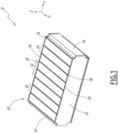
Figure 1 is a schematic perspective view of a part of an electric device comprising an assembly according to a first embodiment of the invention; -
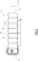
Figure 2 is a schematic side view of the assembly depicted inFigure 1 ; and -
Figure 3 is a schematic side view of an assembly according to a second embodiment of the invention. - An
electrical device 10 according to a first embodiment of the invention will be described with reference toFigure 1 and2 . - The
electrical device 10 is only partially depicted inFigure 1 and is for example a battery, a battery pack, or a battery module intended to be assembled with other modules in order to form a battery. - The
electrical device 10 is for example intended to be installed in an electric or hybrid motor vehicle (not shown). - The
electrical device 10 defines a longitudinal direction X that is for example the direction of travel of the vehicle, and a transverse direction Y perpendicular to the longitudinal direction X and which is for example the transverse direction of the vehicle. - A third direction Z is further defined which is perpendicular to the longitudinal direction X and the transverse direction Y, and which is for example intended to be substantially vertical when the vehicle is on a horizontal surface (not shown).
- The
electrical device 10 comprises at least oneassembly 12, theassembly 12 comprising afirst end 14 andsecond end 16 opposed to each other along the transverse direction Y and further comprising afirst side 18 and asecond side 20 opposed to each other along the longitudinal direction X. - The
electrical device 10 preferably comprises a plurality ofassembly 12 electrically and mechanically connected to each other. - As shown in
Figure 1 , theelectrical device 10 preferably comprises, for eachassembly 12, twoside plates 22 and twoend plates 24. - In particular, each of the two
side plates 22 lies against one of thefirst side 18 and thesecond side 20 of theassembly 12, and preferably covers it entirely. - Each of the two
end plates 24 lies against one of afirst end 14 andsecond end 16 of theassembly 12, and preferably covers it entirely. - The
assembly 12 comprises a plurality ofelectrochemical cells 26 arranged along the transverse direction Y, especially between the twoend plates 24. - The
assembly 12 preferably comprises at least fourelectrochemical cells 26. - In the example shown in the figures, the
assembly 12 comprises eightelectrochemical cells 26. - Furthermore, the
assembly 12 comprises a plurality ofinsulating layers 28, each of theinsulating layers 28 extending perpendicularly to the transverse direction Y, i.e. along the longitudinal direction X, and being arranged along the transverse direction Y between two adjacentelectrochemical cells 26. - In particular, the
assembly 12 consists of a simple alternation ofelectrochemical cells 26 andinsulating layers 28. - Preferably, the
electrochemical cells 26 and theinsulating layers 28 are arranged successively against each other in the transverse direction Y, so that there is no mechanical gap between these elements. - The
assembly 12 preferably comprises at least threeinsulating layers 28. - In particular, the
assembly 12 comprises a number ofinsulating layer 28 corresponding to the number ofelectrochemical cells 26 minus one. - In the example shown in the figures, the
assembly 12 comprises seveninsulating layers 28. - The
insulating layers 28 is for example a plate, a foam or a gel of a thermal insulating material. - Preferably, the
insulating layers 28 are made of a material selected from silicone, aerogel, fiberglass, Mica, and a phase-change material. - The plurality of
insulating layers 28 consists of afirst end group 30 of insulating layers, acentral group 32 of insulating layers and asecond end 34 group of insulating layers. - Each of the
first end group 30, thecentral group 32 and thesecond end group 34 comprises at least oneinsulating layer 28. - The
first end group 30, thecentral group 32 and thesecond end group 34 are successive and arranged in that particular order along the transverse direction Y. - In particular, as shown in
Figures 1 and2 , theinsulating layers 28 of thefirst end group 30 are nearest to thefirst end 14 of theassembly 12. Theinsulating layers 28 of thesecond end group 34 are nearest to thesecond end 16 of theassembly 12. Theinsulating layers 28 ofcentral group 32 are located between theinsulating layers 28 of thefirst end group 30 and theinsulating layers 28 of thesecond end group 34 along the transverse direction Y. - Preferably, the
first end group 30 and thesecond end group 34 have a same number ofinsulating layers 28. - In the example shown in
Figures 1 and2 , each of thefirst end group 30 and thesecond end group 34 is composed of two insulatinglayers 28, and thecentral group 34 is composed of three insulatinglayers 28. - Advantageously, the
first end group 30 and thesecond end group 34 are symmetrical to each other with respect to a median plane XZ of theassembly 12. The median plan XZ of theassembly 12 is a plane perpendicular to the transverse direction Y and is preferably at the same distance from eachend assembly 12. - Each of the insulating
layers 28 has a thermal resistance rth along the transverse direction Y. This thermal resistance rth quantifies the surface resistance to a heat flow along the transverse direction Y between two isotherms. For each insulatinglayer 28, the two isotherms are preferably two plane surfaces of the insulatinglayer 28 parallel to each other, each lying against one of the correspondingelectrochemical cells 26. - The thermal resistance rth along the transverse direction Y of each of the insulating
layers 28 is for example defined by the following formula:
layer 28 and λ is the thermal conductivity of the insulatinglayer 28. - More specifically, the thickness T of each insulating
layer 28 is defined in the transverse direction Y, and corresponds to the gap along the transverse direction Y between the two nearbyelectrochemical cells 26 as illustrated inFigure 2 . - According to the invention, the arithmetical mean of thermal resistances rth of the
first end group 30 and the arithmetical mean of thermal resistances rth of thesecond end group 34 are higher than the arithmetical mean of thermal resistances rth of thecentral group 32. - Preferably, the lowest thermal resistance rth in the
first end group 30 and the lowest thermal resistance rth in thesecond end group 34 are at least 10% higher, preferably at least 50% higher, than the highest thermal resistance rth in thecentral group 32. - In the first embodiment of the invention, the thermal resistances rth of the
first end group 30 all have the same value +/- 5% and the thermal resistances rth of thesecond end group 34 all have the same value +/- 5%. - More specifically, the value of the thermal resistances rth of the
first end group 30 is equal +/- 5% to the value of the thermal resistances rth of thesecond end group 34. - Moreover, in the first embodiment of the invention, the thermal resistances rth of the
central group 32 all have the same value +/- 5%. - More particularly, in the first embodiment of the invention illustrated in
Figures 1 and2 , the thermal conductivities λ of the insulatinglayers 28 of theassembly 12 all have the same value +/- 5% and the variation of thermal resistances rth is obtained by a variation of thicknesses T of the insulating layers 28. - To this end, the arithmetical mean of thicknesses T of the
first end group 30 and the arithmetical mean of thicknesses T of thesecond end group 34 are larger than the arithmetical mean of the thicknesses T of thecentral group 32. - Preferably, the lowest thickness T in the
first end group 30 and the lowest thickness T in thesecond end group 34 are at least 10% larger, preferably at least 50% larger, than the highest thickness T in thecentral group 32. - More specifically, as shown in
Figure 2 , the thicknesses T of thefirst end group 30 all have the same value +/- 5% and the thicknesses T of thesecond end group 34 all have the same value +/- 5%. - Preferably, the value of the thicknesses T of the
first end group 30 is equal to the value of the thicknesses T of thesecond end group 34. - For example, the thicknesses T of the
first end group 30 and the thicknesses T of thesecond end group 34 are comprised between 2 mm and 6 mm, preferably between 2.5 mm and 4.5 mm. - Moreover, as shown in
Figure 2 , the thicknesses T of thecentral group 32 all have the same value +/- 5%. - For example, the thicknesses T of the insulating
layers 28 of thecentral group 32 are comprised between 0.1 mm and 4 mm, preferably between 0.5 mm and 3 mm. - The behavior of
such assembly 12 in case of heating in one of theelectrochemical cells 26 will now be described with reference toFigure 2 . - As shown in
Figure 2 , when heat is generated at anelectrochemical cell 26 near thefirst end 14 of theassembly 12, the heat H propagates to the neighboringelectrochemical cells 26 along the transverse direction Y towards thesecond end 16. - The same applies when heat is generated at an
electrochemical cell 26 near thesecond end 16 of theassembly 12. - On the contrary, when heat is generated at an
electrochemical cell 26 near the median plan XZ of theassembly 12, i.e. in the middle of theassembly 12, the heat propagates to the neighboringelectrochemical cells 26 along the transverse direction Y in both ways, i.e. towards thefirst end 14 and towards thesecond end 16. - As the heat is propagated in both ways, the thermal resistance required in the middle of the
assembly 12 is actually smaller as the thermal resistance required near theends - Thus, the smaller thermal resistances rth of the
central group 32 are sufficient to prevent, or at least delay, the thermal runaway propagating in both ways in the middle of theassembly 12. - Furthermore, the higher thermal resistances rth of the
first end group 30 and of thesecond end group 34 allow efficiently preventing, or at least delaying, the thermal runaway propagating in only one way. - The
assembly 12 according to the invention therefore allows preventing thermal runway in theelectrical device 10 in an efficient way at any point of the battery. - Indeed, such variation of the thermal resistance rth along the transverse direction Y, and in particular of the thickness T, of the insulating
layers 28 allows optimizing the thermal insulation by adapting the thermal resistance rth according to the position along the transverse direction Y, and thus according to the required thermal insulation. - This allows reducing the cost of the insulating
layers 28, and thus of theelectrical device 10. - Furthermore, this allows reducing the total length of the
assembly 12 along the transverse direction Y by avoiding the use of too thick insulating layers 28. - This advantage makes it possible to increase the energy density of the
electrical device 10. - With reference to
Figure 3 , anassembly 120 according to a second embodiment of the invention is described. Theassembly 120 is analogous to theassembly 12 shown inFigures 1 and2 . Similar elements have the same numerical references and will not be described again. Only the differences will be described in detail below. - Unlike the first embodiment, the thermal resistances rth of the
first end group 30 do not all have the same value and the thermal resistances rth of thesecond end group 34 do not all have the same value. - More particularly, in this second embodiment, the thermal resistance rth of each of the insulating
layers 28 of thefirst end group 30 and the thermal resistance rth of each of the insulatinglayers 28 of thesecond end group 34 increases as a function of the distance of said insulatinglayer 28 from the median plan XZ of theassembly 12. - In other words, the further away an insulating
layer 28 of thefirst end group 30 is from the median plan XZ of theassembly 12, the higher is the thermal resistance rth of said insulatinglayer 28. The same applies for the insulatinglayers 28 of thesecond end group 34. - In particular, as shown in
Figure 3 , the thickness T of each of the insulatinglayers 28 of thefirst end group 30 and the thickness T of each of the insulatinglayers 28 of thesecond end group 34 increases as a function of the distance of the insulatinglayer 28 from the median plan XZ of theassembly 12. - In the example showed in
Figure 3 , the thicknesses T of thefirst end group 30 and the thicknesses T of thesecond end group 34 increase with a constant step, for example equal to 0.5 mm. - Furthermore, unlike the first embodiment, the thermal resistances rth of the
central group 32 do not all have the same value. - More particularly, in this second embodiment, the thermal resistance rth of each of the insulating
layers 28 of thecentral group 32 increases as a function of the distance of said insulatinglayer 28 from the median plan XZ of theassembly 12. - In other words, the further away an insulating
layer 28 of thecentral group 32 is from the median plan XZ of theassembly 12, the higher is the thermal resistance rth of said insulatinglayer 28. - In particular, as shown in
Figure 3 , the thickness T of each of the insulatinglayers 28 of thecentral group 32 increases as a function of the distance of said insulatinglayer 28 from the median plan XZ. - In the example showed in
Figure 3 , the thicknesses T of the insulatinglayers 28 of thecentral group 32 increase with a constant step, for example equal to 0.5 mm. - The invention is not limited to the previously described embodiments illustrated in the drawings.
- In particular, a combination of the first embodiment and the second embodiment is possible.
- More specifically, as a variant, the thermal resistances rth of the
first end group 30 all have the same value +/- 5% and the thermal resistances rth of thesecond end group 34 all have the same value +/- 5%. However, the thermal resistance rth of each of the insulatinglayers 28 of thecentral group 32 increases as a function of the distance of said insulatinglayer 28 from the median plan XZ of theassembly 12. - In another variant, the thermal resistance rth of each of the insulating
layers 28 of thefirst end group 30 and the thermal resistance rth of each of the insulatinglayers 28 of thesecond end group 34 increases as a function of the distance of said insulatinglayer 28 from the median plan XZ of theassembly 12. However, the thicknesses T of thecentral group 32 all have the same value +/- 5%. - In another particular embodiment of the invention (not shown), the thicknesses T of the insulating
layers 28 of theassembly 12 all have the same value +/- 5% and the variation of thermal resistances rth is obtained by a variation of thermal conductivities λ of the insulating layers 28. - Particularly, the arithmetical mean of the thermal conductivities λ of the insulating
layers 28 of thefirst end group 30 and the arithmetical mean of the thermal conductivities λ of thesecond end group 34 are lower than the arithmetical mean of the thermal conductivities λ of the insulatinglayers 28 of thecentral group 32. - All the embodiments and variants described above for the variation of thicknesses T also apply to the variation of thermal conductivities λ of the insulating layers 28.
- The variation of thermal conductivities λ of the insulating
layers 28 is for example obtained by selecting different insulating materials according to the desired thermal conductivity λ. - For example, the insulating
layers 28 of thefirst end group 30 and the insulatinglayers 28 of thesecond end group 34 are made of a first material and the insulatinglayers 28 of thecentral group 32 are made of a second material, the second material being different from the first material. - Preferably, the first material has a lower thermal conductivities λ than the second material.
- The first material and the second material are preferably selected from silicone, aerogel, fiberglass, Mica, and a phase-change material.
- In another particular embodiment of the invention not shown, the variation of thermal resistances rth is obtained by variation at the same time of thicknesses T and of the thermal conductivities λ of the insulating
layers 28, according to the one of the embodiments and variants described above.
Claims (15)
- An assembly (12) comprising:- a plurality of electrochemical cells (26) arranged along a transverse direction (Y), and- a plurality of insulating layers (28), each of the insulating layers (28) extending perpendicularly to the transverse direction (Y) and being arranged along the transverse direction (Y) between two adjacent electrochemical cells (26), each of the insulating layers (28) having a thermal resistance (rth ) along the transverse direction (Y),the plurality of insulating layers (28) consisting of a first end group (30) of insulating layers, a central group (32) of insulating layers and a second end group (34) of insulating layers, the first end group (30), the central group (32) and the second end group (34) being successive and arranged in that particular order along the transverse direction (Y),characterized in that the arithmetical mean of thermal resistances (rth ) of the first end group (30) and the arithmetical mean of thermal resistances (rth ) of the second end group (34) are higher than the arithmetical mean of thermal resistances (rth ) of the central group (32).
- The assembly according to claim 1, wherein the first end group (30) and the second end group (34) have a same number of insulating layers (28).
- The assembly according to claim 1 or 2, wherein the lowest thermal resistance (rth ) in the first end group (30) and the lowest thermal resistance (rth ) in the second end group (34) are at least 10% higher, preferably at least 50% higher, than the highest thermal resistance (rth ) in the central group (32).
- The assembly according to any one of the preceding claims, wherein the thermal resistances (rth ) of the first end group (30) all have the same value +/- 5% and the thermal resistances (rth ) of the second end group (34) all have the same value +/- 5%.
- The assembly according to claim 4, wherein the value of the thermal resistances (rth ) of the first end group (30) is equal +/- 5% to the value of the thermal resistances (rth ) of the second end group (34).
- The assembly according to any one of the claims 1 to 3, wherein the thermal resistance (rth ) of each of the insulating layers (28) of the first end group (30) and the thermal resistance (rth ) of each of the insulating layers (28) of the second end group (34) increases as a function of the distance of said insulating layer (28) from a median plan (XZ) of the assembly (12), the median plan (XZ) being perpendicular to the transverse direction (Y).
- The assembly according to any one of the preceding claims, wherein the thermal resistances (rth ) of the central group (32) all have the same value +/- 5%.
- The assembly according to any one of the claims 1 to 6, wherein the thermal resistance (rth ) of each of the insulating layers (28) of the central group (32) increases as a function of the distance of said insulating layer (28) from a median plan (XZ) of the assembly (12), the median plan (XZ) being perpendicular to the transverse direction (Y).
- The assembly according to any one of the preceding claims, wherein each of the insulating layers (28) defines a thickness (T) in the transverse direction (Y), the arithmetical mean of thicknesses (T) of the first end group (30) and the arithmetical mean of thicknesses (T) of the second end group (34) being larger than the arithmetical mean of thicknesses (T) of the central group (32).
- The assembly according to claim 9, wherein the lowest thickness (T) in the first end group (30) and the lowest thickness (T) in the second end group (34) are at least 10% larger, preferably at least 50% larger, than the highest thickness (T) in the central group (32).
- The assembly according to any one of the preceding claims, wherein the thicknesses (T) of the first end group (30) and the thicknesses (T) of the second end group (34) are comprised between 2 mm and 6 mm, preferably between 3 mm and 4.5 mm and/or the thicknesses (T) of the central group (32) are comprised between 0.1 mm and 4 mm, preferably between 0.5 mm and 3 mm.
- The assembly according to any one of the preceding claims, wherein each of the insulating layers (28) has a thermal conductivity (λ), the arithmetical mean of the thermal conductivities (λ) of the first end group (30) and the arithmetical mean of the thermal conductivities (λ) of the second end group (34) being lower than the arithmetical mean of the central group (32).
- The assembly according to any one of the preceding claims, wherein the insulating layers (28) are made of a material selected from silicone, aerogel, fiberglass, Mica, and a phase-change material.
- The assembly according to any one of the preceding claims, wherein the insulating layers (28) of the first end group (30) and the insulating layers (28) of the second end group (34) are made of a first material and the insulating layers (28) of the central group (32) are made of a second material, the second material being different from the first material.
- An electrical device (10), such as a battery module or a battery, comprising at least one assembly (12) according to any one of the preceding claims.
Priority Applications (2)
| Application Number | Priority Date | Filing Date | Title |
|---|---|---|---|
| EP22306489.0A EP4350844A1 (en) | 2022-10-05 | 2022-10-05 | An assembly comprising a plurality of electrochemical cells and an electrical device comprising such assembly |
| PCT/EP2023/077523 WO2024074590A2 (en) | 2022-10-05 | 2023-10-05 | An assembly comprising a plurality of electrochemical cells and an electrical device comprising such assembly |
Applications Claiming Priority (1)
| Application Number | Priority Date | Filing Date | Title |
|---|---|---|---|
| EP22306489.0A EP4350844A1 (en) | 2022-10-05 | 2022-10-05 | An assembly comprising a plurality of electrochemical cells and an electrical device comprising such assembly |
Publications (1)
| Publication Number | Publication Date |
|---|---|
| EP4350844A1 true EP4350844A1 (en) | 2024-04-10 |
Family
ID=83691232
Family Applications (1)
| Application Number | Title | Priority Date | Filing Date |
|---|---|---|---|
| EP22306489.0A Pending EP4350844A1 (en) | 2022-10-05 | 2022-10-05 | An assembly comprising a plurality of electrochemical cells and an electrical device comprising such assembly |
Country Status (2)
| Country | Link |
|---|---|
| EP (1) | EP4350844A1 (en) |
| WO (1) | WO2024074590A2 (en) |
Citations (6)
| Publication number | Priority date | Publication date | Assignee | Title |
|---|---|---|---|---|
| US20100136404A1 (en) * | 2009-08-31 | 2010-06-03 | Tesla Motors, Inc. | Thermal barrier structure for containing thermal runaway propagation within a battery pack |
| US20110159340A1 (en) * | 2009-12-25 | 2011-06-30 | Industrial Technology Research Institute | Protection structure forthermal dissipation and preventing thermal runaway diffusion in battery system |
| EP3432411A1 (en) * | 2017-07-17 | 2019-01-23 | Samsung SDI Co., Ltd. | Secondary battery module |
| CN112467285A (en) * | 2020-12-14 | 2021-03-09 | 天津市捷威动力工业有限公司 | Battery module for delaying thermal runaway and vehicle using same |
| EP3793000A1 (en) * | 2019-09-05 | 2021-03-17 | Samsung SDI Co., Ltd. | Energy storage module |
| US20210257690A1 (en) * | 2020-02-18 | 2021-08-19 | Rogers Corporation | Thermal management multilayer sheet for a battery |
-
2022
- 2022-10-05 EP EP22306489.0A patent/EP4350844A1/en active Pending
-
2023
- 2023-10-05 WO PCT/EP2023/077523 patent/WO2024074590A2/en not_active Ceased
Patent Citations (6)
| Publication number | Priority date | Publication date | Assignee | Title |
|---|---|---|---|---|
| US20100136404A1 (en) * | 2009-08-31 | 2010-06-03 | Tesla Motors, Inc. | Thermal barrier structure for containing thermal runaway propagation within a battery pack |
| US20110159340A1 (en) * | 2009-12-25 | 2011-06-30 | Industrial Technology Research Institute | Protection structure forthermal dissipation and preventing thermal runaway diffusion in battery system |
| EP3432411A1 (en) * | 2017-07-17 | 2019-01-23 | Samsung SDI Co., Ltd. | Secondary battery module |
| EP3793000A1 (en) * | 2019-09-05 | 2021-03-17 | Samsung SDI Co., Ltd. | Energy storage module |
| US20210257690A1 (en) * | 2020-02-18 | 2021-08-19 | Rogers Corporation | Thermal management multilayer sheet for a battery |
| CN112467285A (en) * | 2020-12-14 | 2021-03-09 | 天津市捷威动力工业有限公司 | Battery module for delaying thermal runaway and vehicle using same |
Also Published As
| Publication number | Publication date |
|---|---|
| WO2024074590A2 (en) | 2024-04-11 |
| WO2024074590A3 (en) | 2024-05-16 |
Similar Documents
| Publication | Publication Date | Title |
|---|---|---|
| CN111033876B (en) | Battery pack | |
| CN102593389B (en) | Vehicle battery packaging | |
| KR101112442B1 (en) | Battery Module Assembly of Improved Cooling Efficiency | |
| EP3131161B1 (en) | Current distribution system for a battery assembly utilizing non-overlapping bus bars | |
| EP3783734A1 (en) | Battery assembly, battery pack and vehicle | |
| US10511069B2 (en) | Battery | |
| US20120115011A1 (en) | Battery module having battery cell holder | |
| JP2022062288A (en) | Battery module | |
| KR102514497B1 (en) | Battery module and battery packr including the same | |
| JP2018530857A (en) | Heating panel | |
| CN114051673B (en) | Power storage group | |
| CN115621604A (en) | Battery and motor vehicle with integrated bus cooling | |
| EP4350844A1 (en) | An assembly comprising a plurality of electrochemical cells and an electrical device comprising such assembly | |
| CN115066799A (en) | Battery module and battery pack | |
| KR102272268B1 (en) | Current collector system for battery module, battery module, and vehicle | |
| CN116231193B (en) | A diamond-shaped battery cell system | |
| KR102767093B1 (en) | Battery unit that prevents a series of explosion of battery cells | |
| CN116806387A (en) | Battery cell for an electric energy accumulator with internal heating of the battery cell and battery for a motor vehicle | |
| CN218586112U (en) | Heating element, battery module, battery package and consumer | |
| JP5298604B2 (en) | Battery pack | |
| CN222546606U (en) | Battery modules, battery packs and battery system components | |
| JP7652111B2 (en) | Energy Storage Stack | |
| US20240213567A1 (en) | Thermal interlayer device with sandwich structure for battery modules to enhance cooling and prevent thermal propagation | |
| EP4654339A1 (en) | Battery module, and battery pack and vehicle comprising same | |
| EP4468453A1 (en) | Thermal barrier and thermal fin for a battery apparatus |
Legal Events
| Date | Code | Title | Description |
|---|---|---|---|
| PUAI | Public reference made under article 153(3) epc to a published international application that has entered the european phase |
Free format text: ORIGINAL CODE: 0009012 |
|
| STAA | Information on the status of an ep patent application or granted ep patent |
Free format text: STATUS: THE APPLICATION HAS BEEN PUBLISHED |
|
| AK | Designated contracting states |
Kind code of ref document: A1 Designated state(s): AL AT BE BG CH CY CZ DE DK EE ES FI FR GB GR HR HU IE IS IT LI LT LU LV MC ME MK MT NL NO PL PT RO RS SE SI SK SM TR |
|
| P01 | Opt-out of the competence of the unified patent court (upc) registered |
Effective date: 20240420 |
|
| STAA | Information on the status of an ep patent application or granted ep patent |
Free format text: STATUS: REQUEST FOR EXAMINATION WAS MADE |
|
| 17P | Request for examination filed |
Effective date: 20240927 |
|
| RBV | Designated contracting states (corrected) |
Designated state(s): AL AT BE BG CH CY CZ DE DK EE ES FI FR GB GR HR HU IE IS IT LI LT LU LV MC ME MK MT NL NO PL PT RO RS SE SI SK SM TR |
|
| RAP3 | Party data changed (applicant data changed or rights of an application transferred) |
Owner name: AUTOMOTIVE CELLS COMPANY SE |
|
| RAP3 | Party data changed (applicant data changed or rights of an application transferred) |
Owner name: AUTOMOTIVE CELLS COMPANY SE |