EP4350825B1 - Rechargeable battery - Google Patents
Rechargeable battery Download PDFInfo
- Publication number
- EP4350825B1 EP4350825B1 EP23197360.3A EP23197360A EP4350825B1 EP 4350825 B1 EP4350825 B1 EP 4350825B1 EP 23197360 A EP23197360 A EP 23197360A EP 4350825 B1 EP4350825 B1 EP 4350825B1
- Authority
- EP
- European Patent Office
- Prior art keywords
- electrode
- case
- rechargeable battery
- welding
- collecting plate
- Prior art date
- Legal status (The legal status is an assumption and is not a legal conclusion. Google has not performed a legal analysis and makes no representation as to the accuracy of the status listed.)
- Active
Links
Images


Classifications
-
- H—ELECTRICITY
- H01—ELECTRIC ELEMENTS
- H01M—PROCESSES OR MEANS, e.g. BATTERIES, FOR THE DIRECT CONVERSION OF CHEMICAL ENERGY INTO ELECTRICAL ENERGY
- H01M50/00—Constructional details or processes of manufacture of the non-active parts of electrochemical cells other than fuel cells, e.g. hybrid cells
- H01M50/50—Current conducting connections for cells or batteries
- H01M50/531—Electrode connections inside a battery casing
- H01M50/533—Electrode connections inside a battery casing characterised by the shape of the leads or tabs
-
- H—ELECTRICITY
- H01—ELECTRIC ELEMENTS
- H01M—PROCESSES OR MEANS, e.g. BATTERIES, FOR THE DIRECT CONVERSION OF CHEMICAL ENERGY INTO ELECTRICAL ENERGY
- H01M10/00—Secondary cells; Manufacture thereof
- H01M10/04—Construction or manufacture in general
- H01M10/0422—Cells or battery with cylindrical casing
-
- H—ELECTRICITY
- H01—ELECTRIC ELEMENTS
- H01M—PROCESSES OR MEANS, e.g. BATTERIES, FOR THE DIRECT CONVERSION OF CHEMICAL ENERGY INTO ELECTRICAL ENERGY
- H01M10/00—Secondary cells; Manufacture thereof
- H01M10/04—Construction or manufacture in general
- H01M10/0431—Cells with wound or folded electrodes
-
- H—ELECTRICITY
- H01—ELECTRIC ELEMENTS
- H01M—PROCESSES OR MEANS, e.g. BATTERIES, FOR THE DIRECT CONVERSION OF CHEMICAL ENERGY INTO ELECTRICAL ENERGY
- H01M10/00—Secondary cells; Manufacture thereof
- H01M10/05—Accumulators with non-aqueous electrolyte
- H01M10/058—Construction or manufacture
- H01M10/0587—Construction or manufacture of accumulators having only wound construction elements, i.e. wound positive electrodes, wound negative electrodes and wound separators
-
- H—ELECTRICITY
- H01—ELECTRIC ELEMENTS
- H01M—PROCESSES OR MEANS, e.g. BATTERIES, FOR THE DIRECT CONVERSION OF CHEMICAL ENERGY INTO ELECTRICAL ENERGY
- H01M50/00—Constructional details or processes of manufacture of the non-active parts of electrochemical cells other than fuel cells, e.g. hybrid cells
- H01M50/10—Primary casings; Jackets or wrappings
- H01M50/102—Primary casings; Jackets or wrappings characterised by their shape or physical structure
- H01M50/107—Primary casings; Jackets or wrappings characterised by their shape or physical structure having curved cross-section, e.g. round or elliptic
-
- H—ELECTRICITY
- H01—ELECTRIC ELEMENTS
- H01M—PROCESSES OR MEANS, e.g. BATTERIES, FOR THE DIRECT CONVERSION OF CHEMICAL ENERGY INTO ELECTRICAL ENERGY
- H01M50/00—Constructional details or processes of manufacture of the non-active parts of electrochemical cells other than fuel cells, e.g. hybrid cells
- H01M50/10—Primary casings; Jackets or wrappings
- H01M50/147—Lids or covers
- H01M50/148—Lids or covers characterised by their shape
- H01M50/152—Lids or covers characterised by their shape for cells having curved cross-section, e.g. round or elliptic
-
- H—ELECTRICITY
- H01—ELECTRIC ELEMENTS
- H01M—PROCESSES OR MEANS, e.g. BATTERIES, FOR THE DIRECT CONVERSION OF CHEMICAL ENERGY INTO ELECTRICAL ENERGY
- H01M50/00—Constructional details or processes of manufacture of the non-active parts of electrochemical cells other than fuel cells, e.g. hybrid cells
- H01M50/10—Primary casings; Jackets or wrappings
- H01M50/147—Lids or covers
- H01M50/166—Lids or covers characterised by the methods of assembling casings with lids
- H01M50/167—Lids or covers characterised by the methods of assembling casings with lids by crimping
-
- H—ELECTRICITY
- H01—ELECTRIC ELEMENTS
- H01M—PROCESSES OR MEANS, e.g. BATTERIES, FOR THE DIRECT CONVERSION OF CHEMICAL ENERGY INTO ELECTRICAL ENERGY
- H01M50/00—Constructional details or processes of manufacture of the non-active parts of electrochemical cells other than fuel cells, e.g. hybrid cells
- H01M50/10—Primary casings; Jackets or wrappings
- H01M50/172—Arrangements of electric connectors penetrating the casing
- H01M50/174—Arrangements of electric connectors penetrating the casing adapted for the shape of the cells
- H01M50/179—Arrangements of electric connectors penetrating the casing adapted for the shape of the cells for cells having curved cross-section, e.g. round or elliptic
-
- H—ELECTRICITY
- H01—ELECTRIC ELEMENTS
- H01M—PROCESSES OR MEANS, e.g. BATTERIES, FOR THE DIRECT CONVERSION OF CHEMICAL ENERGY INTO ELECTRICAL ENERGY
- H01M50/00—Constructional details or processes of manufacture of the non-active parts of electrochemical cells other than fuel cells, e.g. hybrid cells
- H01M50/10—Primary casings; Jackets or wrappings
- H01M50/183—Sealing members
- H01M50/184—Sealing members characterised by their shape or structure
-
- H—ELECTRICITY
- H01—ELECTRIC ELEMENTS
- H01M—PROCESSES OR MEANS, e.g. BATTERIES, FOR THE DIRECT CONVERSION OF CHEMICAL ENERGY INTO ELECTRICAL ENERGY
- H01M50/00—Constructional details or processes of manufacture of the non-active parts of electrochemical cells other than fuel cells, e.g. hybrid cells
- H01M50/10—Primary casings; Jackets or wrappings
- H01M50/183—Sealing members
- H01M50/186—Sealing members characterised by the disposition of the sealing members
-
- H—ELECTRICITY
- H01—ELECTRIC ELEMENTS
- H01M—PROCESSES OR MEANS, e.g. BATTERIES, FOR THE DIRECT CONVERSION OF CHEMICAL ENERGY INTO ELECTRICAL ENERGY
- H01M50/00—Constructional details or processes of manufacture of the non-active parts of electrochemical cells other than fuel cells, e.g. hybrid cells
- H01M50/30—Arrangements for facilitating escape of gases
- H01M50/342—Non-re-sealable arrangements
- H01M50/3425—Non-re-sealable arrangements in the form of rupturable membranes or weakened parts, e.g. pierced with the aid of a sharp member
-
- H—ELECTRICITY
- H01—ELECTRIC ELEMENTS
- H01M—PROCESSES OR MEANS, e.g. BATTERIES, FOR THE DIRECT CONVERSION OF CHEMICAL ENERGY INTO ELECTRICAL ENERGY
- H01M50/00—Constructional details or processes of manufacture of the non-active parts of electrochemical cells other than fuel cells, e.g. hybrid cells
- H01M50/50—Current conducting connections for cells or batteries
- H01M50/528—Fixed electrical connections, i.e. not intended for disconnection
-
- H—ELECTRICITY
- H01—ELECTRIC ELEMENTS
- H01M—PROCESSES OR MEANS, e.g. BATTERIES, FOR THE DIRECT CONVERSION OF CHEMICAL ENERGY INTO ELECTRICAL ENERGY
- H01M50/00—Constructional details or processes of manufacture of the non-active parts of electrochemical cells other than fuel cells, e.g. hybrid cells
- H01M50/50—Current conducting connections for cells or batteries
- H01M50/531—Electrode connections inside a battery casing
- H01M50/536—Electrode connections inside a battery casing characterised by the method of fixing the leads to the electrodes, e.g. by welding
-
- H—ELECTRICITY
- H01—ELECTRIC ELEMENTS
- H01M—PROCESSES OR MEANS, e.g. BATTERIES, FOR THE DIRECT CONVERSION OF CHEMICAL ENERGY INTO ELECTRICAL ENERGY
- H01M50/00—Constructional details or processes of manufacture of the non-active parts of electrochemical cells other than fuel cells, e.g. hybrid cells
- H01M50/50—Current conducting connections for cells or batteries
- H01M50/531—Electrode connections inside a battery casing
- H01M50/538—Connection of several leads or tabs of wound or folded electrode stacks
-
- H—ELECTRICITY
- H01—ELECTRIC ELEMENTS
- H01M—PROCESSES OR MEANS, e.g. BATTERIES, FOR THE DIRECT CONVERSION OF CHEMICAL ENERGY INTO ELECTRICAL ENERGY
- H01M50/00—Constructional details or processes of manufacture of the non-active parts of electrochemical cells other than fuel cells, e.g. hybrid cells
- H01M50/50—Current conducting connections for cells or batteries
- H01M50/543—Terminals
- H01M50/545—Terminals formed by the casing of the cells
-
- H—ELECTRICITY
- H01—ELECTRIC ELEMENTS
- H01M—PROCESSES OR MEANS, e.g. BATTERIES, FOR THE DIRECT CONVERSION OF CHEMICAL ENERGY INTO ELECTRICAL ENERGY
- H01M50/00—Constructional details or processes of manufacture of the non-active parts of electrochemical cells other than fuel cells, e.g. hybrid cells
- H01M50/50—Current conducting connections for cells or batteries
- H01M50/543—Terminals
- H01M50/547—Terminals characterised by the disposition of the terminals on the cells
-
- H—ELECTRICITY
- H01—ELECTRIC ELEMENTS
- H01M—PROCESSES OR MEANS, e.g. BATTERIES, FOR THE DIRECT CONVERSION OF CHEMICAL ENERGY INTO ELECTRICAL ENERGY
- H01M2220/00—Batteries for particular applications
- H01M2220/30—Batteries in portable systems, e.g. mobile phone, laptop
-
- Y—GENERAL TAGGING OF NEW TECHNOLOGICAL DEVELOPMENTS; GENERAL TAGGING OF CROSS-SECTIONAL TECHNOLOGIES SPANNING OVER SEVERAL SECTIONS OF THE IPC; TECHNICAL SUBJECTS COVERED BY FORMER USPC CROSS-REFERENCE ART COLLECTIONS [XRACs] AND DIGESTS
- Y02—TECHNOLOGIES OR APPLICATIONS FOR MITIGATION OR ADAPTATION AGAINST CLIMATE CHANGE
- Y02E—REDUCTION OF GREENHOUSE GAS [GHG] EMISSIONS, RELATED TO ENERGY GENERATION, TRANSMISSION OR DISTRIBUTION
- Y02E60/00—Enabling technologies; Technologies with a potential or indirect contribution to GHG emissions mitigation
- Y02E60/10—Energy storage using batteries
-
- Y—GENERAL TAGGING OF NEW TECHNOLOGICAL DEVELOPMENTS; GENERAL TAGGING OF CROSS-SECTIONAL TECHNOLOGIES SPANNING OVER SEVERAL SECTIONS OF THE IPC; TECHNICAL SUBJECTS COVERED BY FORMER USPC CROSS-REFERENCE ART COLLECTIONS [XRACs] AND DIGESTS
- Y02—TECHNOLOGIES OR APPLICATIONS FOR MITIGATION OR ADAPTATION AGAINST CLIMATE CHANGE
- Y02P—CLIMATE CHANGE MITIGATION TECHNOLOGIES IN THE PRODUCTION OR PROCESSING OF GOODS
- Y02P70/00—Climate change mitigation technologies in the production process for final industrial or consumer products
- Y02P70/50—Manufacturing or production processes characterised by the final manufactured product
Definitions
- the present disclosure relates to a rechargeable battery, and more particularly, to a rechargeable battery that may connect a current collecting plate to a case at one side of a gasket.
- a cylindrical rechargeable battery includes an electrode assembly for charging and discharging, a case accommodating the electrode assembly, and a cap assembly electrically connected to the electrode assembly to seal an opening side of the case.
- Such rechargeable batteries are disclosed in WO2022/177377 and EP4047702 .
- the electrode assembly is formed by disposing a positive electrode and a negative electrode on both surfaces of a separator, and winding the positive electrode, the separator, and the negative electrode in a jelly roll form.
- one electrode is connected to the cap assembly through the current collecting plate, and the other electrode is connected to the case through a lead tab.
- the cap assembly includes a current interrupt device (CID), and in this case, the opening of the case is closed and sealed by a beading portion and a crimping portion interposing a gasket between the current interrupt device and the case.
- CID current interrupt device
- an inner end of the gasket may interfere with the current collecting plate, and in this case, the sealing force of the gasket with respect to the opening may be deteriorated.
- the current collecting plate may be connected to the beading portion of the case at one side of the gasket.
- an interference phenomenon in which one portion of the current collecting plate is connected to an electrode uncoated portion and the other portion of the current collecting plate presses the electrode uncoated portion may occur.
- the present disclosure has been made in an effort to provide a rechargeable battery that may prevent interference between a current collecting plate and an electrode uncoated portion while securing sealing force of a case opening by a gasket.
- An embodiment provides a rechargeable battery as defined in claim 1 as appended hereto, including: an electrode assembly formed by winding a first electrode, a separator, and a second electrode; a case accommodating the electrode assembly; an electrode terminal installed in an insulating state at a first opening on one side of the case; a first current collecting plate that connects the first electrode to the electrode terminal; a vent plate sealing a second opening on the other side of the case; a second current collecting plate connecting the second electrode to a beading portion of the case at an inner side of the vent plate; and a gasket interposed between the second collecting plate and the vent plate and between the second collecting plate and the case to perform a sealing action by a crimping portion connected to the beading portion, wherein the second current collecting plate includes a base portion disposed on an uncoated portion of the second electrode, a bottom welding portion extending in a radial direction from the base portion and welded to the uncoated portion of the second electrode, and a wing welding portion spaced apart from
- a plurality of the bottom welding portions and a plurality of the wing welding portions may be respectively formed to be alternately disposed in a circumferential direction on the base portion.
- a through-hole may be formed in a center of the base portion, and the bottom welding portion and the elastic portion may be connected by a concave groove at the base portion.
- the bottom welding portion may form a first welding line along a radial direction, and the wing welding portion may form a second welding line along a circumferential direction.
- the wing welding portion may extend in a circumferential direction to be longer than a width of the elastic portion.
- the elastic portion includes a first elastic bending portion that is connected to the base portion to be upwardly bent and then is outwardly bent based on a radial direction, and a second elastic bending portion that is connected to the first elastic bending portion to be upwardly bent and then is outwardly inclined-bent based on a radial direction to be connected to the wing welding portion.
- the gasket may be provided with an escape groove accommodating the wing welding portion.
- the beading portion may be provided with a flat portion formed on an upper side of an inwardly convex curved portion, and the wing welding portion may be welded to the flat portion.
- the escape groove may be formed at a right angle at a side of the wing welding portion, and may be formed at an obtuse angle corresponding to the second elastic bending portion at an inner side based on the radial direction.
- a notch may be formed on an inner surface of the vent plate.
- a gasket is sealed by a crimping portion interposed between a second current collecting plate and a case and connected to a beading portion, it is possible to secure sealing force of a case opening by the gasket and to prevent interference between the second current collecting plate and an electrode uncoated portion.
- FIG. 1 illustrates a longitudinal cross-sectional view of a rechargeable battery according to an embodiment of the present disclosure.
- the rechargeable battery according to the embodiment includes an electrode assembly 10 that functions for charging and discharging, a case 20 accommodating the electrode assembly 10, and a first current collecting plate 31, a second current collecting plate 32, and an electrode terminal 41 connected to the electrode assembly 10, a vent plate 42, and a gasket 50.
- the electrode assembly 10 is formed in a jelly roll state by winding a first electrode 11, a separator 13, and a second electrode 12.
- the first electrode 11 and the second electrode 12 include coating portions 11a and 12a in areas in which active materials are applied on both surfaces of substrates respectively formed of thin metal plates, and non-coated portions 11b and 12b in areas in which the active materials are not applied and the substrates are exposed.
- the first electrode 11 may form a positive electrode by coating a positive electrode active material on an aluminium (Al) substrate
- the second electrode 12 may form a negative electrode by coating a negative electrode active material on a copper (Cu) substrate.
- the uncoated portions 11b and 12b of the first and second electrodes 11 and 12 are provided at both ends of the electrode assembly 10 in a direction of a winding axis (both upper and lower ends in FIG. 1 ), but are provided together with the electrode terminal 41 and the case 20 having different polarities in the same direction.
- the vent plate 42 is disposed at the opposite side of the electrode terminal 41.
- the case 20 is formed in a cylindrical shape to accommodate the electrode assembly 10, and the electrode terminal 41 and the vent plate 42 are provided at both ends of the case 20 in the axial direction by the uncoated portions 11b and 12b, respectively.
- the electrode terminal 41 is connected to the first electrode 11 by the first current collecting plate 31, and the case 20 is connected to the second electrode 12 by the second current collecting plate 32.
- the vent plate 42 is electrically separated from the second collecting plate 32 and the case 20 and has no polarity.
- the electrode terminal 41 connected to the first electrode 11 of the electrode assembly 10 inserted into the case 20 from the outside is installed at one side of the case 20.
- the case 20 includes a first opening 21 partially opened on one side.
- the electrode terminal 41 is installed in an electrical insulation state from the case 20 while forming an airtight structure with respect to an electrolyte by interposing a sealing member 211 in the first opening 21.
- the first current collecting plate 31 is electrically connected to the uncoated portion 11b of the first electrode 11 to be electrically and mechanically connected to the electrode terminal 41.
- the first current collecting plate 31 is electrically connected to the electrode terminal 41 in a structure that reduces resistance by contacting most of the uncoated portion 11b of the first electrode 11.
- the electrode terminal 41 may be connected to the first collecting plate 31 by welding at one end and installed in the first opening 21 of the case 20 in a rivet structure.
- the electrode terminal 41 may be formed to protrude from an outer surface of the case 20 around the first opening 21 to be used as a positive electrode terminal.
- the first current collecting plate 31 becomes a positive electrode current collecting plate.
- the case 20 has a second opening 22 that is completely opened to insert the electrode assembly 10 into the other side.
- the vent plate 42 seals the second opening 22 after inserting the electrode assembly 10 into the case 20, and is electrically separated from the case 20.
- the second current collecting plate 32 is electrically connected to the uncoated portion 12b of the second electrode 12 to be electrically connected to the case 20.
- the second current collecting plate 32 is connected to case 20 in a structure that reduces resistance by contacting most of the uncoated portion 12b of the second electrode 12.
- the vent plate 42 is electrically separated from the second collecting plate 32, and is installed in the second opening 22 of the case 20 through a crimping process. Due to the connection of the second collecting plate 32, the case 20 may be used as a negative electrode terminal. In this case, the second current collecting plate 32 becomes a negative electrode current collecting plate.
- FIG. 2 illustrates a cross-sectional view of a state before a vent plate is coupled by interposing a gasket into a second opening of a case of FIG. 1 .
- the second current collecting plate 32 connects the second electrode 12 to the beading portion 23 of the case 20.
- a beading portion 23 is formed adjacent to the second opening 22 of the case 20, and a crimping portion 24 connected to the beading portion 23 is formed through a crimping process. That is, the case 20 includes the beading portion 23 and the crimping portion 24.
- the beading portion 23 has a structure in which the electrode assembly 10 is recessed toward a center in a diameter direction of the case 20 from an upper side of the case 20 while the electrode assembly 10 is accommodated in the case 20, thereby preventing the electrode assembly 10 from moving up and down.
- the crimping portion 24 is connected to the beading portion 23 in a structure that relatively further protrudes from the beading portion 23 in the diameter direction. By the crimping process, the beading portion 23 is inclined downward while inwardly moving based on the diameter direction.
- the gasket 50 is used in the crimping process. After the crimping process, the gasket 50 is interposed between the second collecting plate 32 and the vent plate 42 and between the second collecting plate 32 and the case 20 to perform sealing-function by the beading portion 23 and the clamping portion 24 connected thereto. In addition, the gasket 50 forms an airtight structure with respect to the electrolyte solution between the second collecting plate 32 and the second opening 22 of the case 20.
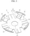
- FIG. 3 illustrates a perspective view of the second current collecting plate applied to FIG. 1 .
- FIG. 4 illustrates a cross-sectional view of the gasket applied to FIG. 2 .
- FIG. 5 illustrates a cross-sectional view of a state in which the vent plate is coupled to the second opening of the case with the gasket interposed in the state of FIG. 2 .
- the second current collecting plate 32 includes a base portion 326, a bottom welding portion 321, an elastic portion 327, and a welding wing portion 322.
- the base portion 326 is placed on the uncoated portion 12b of the second electrode 12.
- the bottom welding portion 321 extends in a radial direction from the base portion 326 to be welded to the uncoated portion 12b of the second electrode 12.
- the welding wing portion 322 is spaced apart from the bottom welding portion 321, is connected to the base portion 326 by the elastic portion 327, and is welded to the beading portion 23.
- the second current collecting plate 32 is formed by cutting and bending an original plate, and has a plurality of bottom welding portions 321 and wing welding portions 322, respectively.
- the bottom welding portion 321 and the wing welding portion 322 are alternately disposed in the base portion 326 along a circumferential direction. Accordingly, the bottom welding portion 321 and the wing welding portion 322 may form a balanced structure along the circumferential direction.
- the bottom welding portion 321 forms a first welding line 324 in the diameter direction.
- the wing welding portion 322 forms a second welding line 325 along the circumferential direction.
- the wing welding portion 322 extends in the circumferential direction to be longer than a width W of the elastic portion 327.
- the bottom welding portion 321 is evenly connected along the circumferential direction in the area of the uncoated portion 12b, and the wing welding portion 322 is evenly connected along the circumferential direction in the area of the beading portion 23.
- the second electrode 12 a uniform current flow is possible along the circumferential direction in the entire area of the beading portion 23 of the case 20.
- the elastic portion 327 may repeatedly form bending in an axial direction (upward) and bending in an outer radial direction.
- the elastic portion 327 includes a first elastic bending portion 271 and a second elastic bending portion 272.
- the first elastic bending portion 271 is connected to the base portion 326 to be bent upwardly and then to be bent outwardly based on the radial direction.
- An upward height H1 of the first elastic bending portion 271 prevents the second elastic bending portion 272 from being separated from the uncoated portion 12b to interfere with the uncoated portion 12b.
- the second elastic bending portion 272 is connected to the first elastic bending portion 271 to be bent upward and then is outwardly inclined-bent based on the radial direction to be connected to the wing welding portion 322.
- a bent upward height H2 of the second elastic bending portion 272 and an inclined angle ⁇ thereof outwardly inclined-bent based on the radial direction prevent interference with the beading portion 23.
- a length L from a bending start point to the upward bending point of the second elastic bending portion 272 in the radial outer direction of the first elastic bending portion 271 imparts elasticity to the elastic portion 327, so that the upwardly bending point of the second elastic bending portion 272 has a force to move upward from the uncoated portion 12b. Accordingly, the length L of the elastic portion 327 further prevents the second elastic bending portion 272 from interfering with the uncoated portion 12b by separating it from the uncoated portion 12b.
- the base portion 326 has a through-hole 323 in a center thereof, and the bottom welding portion 321 and the elastic portion 327 are connected to a concave groove 328 in the base portion 326.
- the through-hole 323 and the concave groove 328 may absorb and alleviate deformation caused by welding the bottom welding portion 321 and the uncoated portion 12b and vibration and impact that may be transmitted between the wing welding portion 322 and the bottom welding portion 321.
- the through-hole 323 and the concave groove 328 may have a size within a range capable of absorbing vibration and impact without increasing current resistance between the wing welding portion 322 and the bottom welding portion 321.
- the beading portion 23 includes a flat portion 232 formed parallel to a flat surface formed by a cross-section of the uncoated portion 12b at an upper side of an inwardly convex curved portion 231.
- the wing welding portion 322 of the second current collecting plate 32 is welded to the flat portion 232. Accordingly, the second collecting plate 32 is stably contacted and welded to the beading portion 23 of the case 20 to further realize a uniform flow of current.
- the contact area and welding area with the flat portion 232 may be further increased to prevent an increase in resistance in the welding portion.
- the gasket 50 has an escape groove 51 accommodating the wing welding portion 322.
- the escape groove 51 increases stability of the gasket 50 by reducing deformation of the gasket 50 between the wing welding portion 322 and the vent plate 42 during the crimping process.
- the gasket 50 further includes a compression portion 52 that comes into contact with the flat portion 232 at the outer side based on the radial direction of the escape groove 51 to act as a compression airtight seal. Despite the escape groove 51, the compression portion 52 implements a sufficient airtight action between the flat portion 232 and the vent plate 42.
- the escape groove 51 is formed at a right angle at the compression portion 52 side to stably accommodate the end of the wing welding portion 322 to prevent misalignment between the wing welding portion 322 and the gasket 50.
- the escape groove 51 may be formed at an obtuse angle at the inner side based on the radial direction to induce coupling of the bending structure of the wing welding portion 322, the elastic portion 327, and the second elastic bending portion 272 and to stably accommodate the bending structure of the wing welding portion 322, the elastic portion 327, and the second elastic bending portion 272.
- the wing welding portion 322, the elastic portion 327, and the second elastic bending portion 272 may be bent to correspond to the obtuse structure of the escape groove 51.
- the gasket 50 has a through-hole 53 inside the escape groove 51 in the radius direction.
- the through-hole 53 connects an upper surface 54 and a lower surface 55 of the gasket 50 at right angles to the side thereof.
- the gasket 50 further includes a convex portion 56 convexly formed at the inside to further form the through-hole 53 inward in a through-direction.
- the convex portion 56 prevents the bending structure of the wing welding portion 322, the elastic portion 327, and the second elastic bending portion 272 from being pushed to the vent plate 42.
- the through-hole 53 of the gasket 50 is formed to correspond to an outer portion 424 of the vent plate 42, the inner side of the gasket 50 compressed and deformed by the crimping process may be prevented from interfering with the second collecting plate 32.
- the vent plate 42 forms a notch 421 on the inner surface thereof. During a rechargeable battery event, the notch 421 is cut to discharge internal pressure, thereby preventing secondary explosion.
- the vent plate 42 is formed in a circular plate and includes a central portion 422, a convex portion 423, and the outer portion 424.
- the central portion 422 is formed to be concave toward the electrode assembly 10
- the convex portion 423 is formed to be convex so as to be away from the electrode assembly 10 at the outer side based on the diameter direction of the center portion 422, and the outer portion 424 forms the same plane as the central portion 422 toward the electrode assembly 10 at the outer side based on the diameter direction of the convex portion 423.
- an inner inclined surface 425 and an outer inclined surface 426 are formed at a portion where the central portion 422 and the convex portion 423 are connected and a portion where the convex portion 423 and the outer portion 424 are connected.
- the inner inclined surface 425 and the outer inclined surface 426 increase the rigidity of the vent plate 42 against the internal pressure of the rechargeable battery.
- the notch 421 is formed on the inner surface of the convex portion 423 and the outer inclined surface 426 to receive intensive internal pressure during an event so that it may be easily cut.
- the notch 421 may be formed in the entire area along the circumferential direction of the vent plate 42, or may be formed in a plurality spaced apart at predetermined intervals.
- electrode assembly 11 first electrode 11a, 12a: coating portion 11b, 12b: uncoated portion 12: second electrode 13: separator 20: case 21: first opening 22: second opening 23: beading portion 24: crimping portion 31: first current collecting plate 32: second current collecting plate 41: electrode terminal 42: vent plate 50: gasket 51: escape groove 52: compression portion 53, 323: through-hole 54: upper surface 55: lower surface 56: convex portion 211: sealing member 231: inwardly convex curved portion 232: flat portion 271: first elastic bending portion 272: second elastic bending portion 321: bottom welding portion 322: wing welding portion 324: first welding line 325: second welding line 326: base portion 327: elastic portion
Landscapes
- Chemical & Material Sciences (AREA)
- Chemical Kinetics & Catalysis (AREA)
- Electrochemistry (AREA)
- General Chemical & Material Sciences (AREA)
- Engineering & Computer Science (AREA)
- Manufacturing & Machinery (AREA)
- Connection Of Batteries Or Terminals (AREA)
Description
- The present disclosure relates to a rechargeable battery, and more particularly, to a rechargeable battery that may connect a current collecting plate to a case at one side of a gasket.
- Demand for rechargeable batteries as an energy source is increasing according to demand for mobile devices and technological development. For example, a cylindrical rechargeable battery includes an electrode assembly for charging and discharging, a case accommodating the electrode assembly, and a cap assembly electrically connected to the electrode assembly to seal an opening side of the case. Such rechargeable batteries are disclosed in
WO2022/177377 andEP4047702 . - For example, the electrode assembly is formed by disposing a positive electrode and a negative electrode on both surfaces of a separator, and winding the positive electrode, the separator, and the negative electrode in a jelly roll form. In the electrode assembly, one electrode is connected to the cap assembly through the current collecting plate, and the other electrode is connected to the case through a lead tab.
- The cap assembly includes a current interrupt device (CID), and in this case, the opening of the case is closed and sealed by a beading portion and a crimping portion interposing a gasket between the current interrupt device and the case. In this case, as the gasket is compressed by the beading portion and the crimping portion, an inner end of the gasket may interfere with the current collecting plate, and in this case, the sealing force of the gasket with respect to the opening may be deteriorated.
- In order to maintain the sealing force of the gasket, the current collecting plate may be connected to the beading portion of the case at one side of the gasket. In this case, an interference phenomenon in which one portion of the current collecting plate is connected to an electrode uncoated portion and the other portion of the current collecting plate presses the electrode uncoated portion may occur.
- The present disclosure has been made in an effort to provide a rechargeable battery that may prevent interference between a current collecting plate and an electrode uncoated portion while securing sealing force of a case opening by a gasket.
- An embodiment provides a rechargeable battery as defined in claim 1 as appended hereto, including: an electrode assembly formed by winding a first electrode, a separator, and a second electrode; a case accommodating the electrode assembly; an electrode terminal installed in an insulating state at a first opening on one side of the case; a first current collecting plate that connects the first electrode to the electrode terminal; a vent plate sealing a second opening on the other side of the case; a second current collecting plate connecting the second electrode to a beading portion of the case at an inner side of the vent plate; and a gasket interposed between the second collecting plate and the vent plate and between the second collecting plate and the case to perform a sealing action by a crimping portion connected to the beading portion, wherein the second current collecting plate includes a base portion disposed on an uncoated portion of the second electrode, a bottom welding portion extending in a radial direction from the base portion and welded to the uncoated portion of the second electrode, and a wing welding portion spaced apart from the bottom welding portion to be connected to the base portion by an elastic portion and welded to the beading portion.
- A plurality of the bottom welding portions and a plurality of the wing welding portions may be respectively formed to be alternately disposed in a circumferential direction on the base portion.
- A through-hole may be formed in a center of the base portion, and the bottom welding portion and the elastic portion may be connected by a concave groove at the base portion.
- The bottom welding portion may form a first welding line along a radial direction, and the wing welding portion may form a second welding line along a circumferential direction.
- The wing welding portion may extend in a circumferential direction to be longer than a width of the elastic portion.
- The elastic portion includes a first elastic bending portion that is connected to the base portion to be upwardly bent and then is outwardly bent based on a radial direction, and a second elastic bending portion that is connected to the first elastic bending portion to be upwardly bent and then is outwardly inclined-bent based on a radial direction to be connected to the wing welding portion.
- The gasket may be provided with an escape groove accommodating the wing welding portion.
- The beading portion may be provided with a flat portion formed on an upper side of an inwardly convex curved portion, and the wing welding portion may be welded to the flat portion.
- The escape groove may be formed at a right angle at a side of the wing welding portion, and may be formed at an obtuse angle corresponding to the second elastic bending portion at an inner side based on the radial direction.
- A notch may be formed on an inner surface of the vent plate.
- At least some of the above and other features of the invention are set out in the claims.
- As described above, according to the embodiment of the present disclosure, since a gasket is sealed by a crimping portion interposed between a second current collecting plate and a case and connected to a beading portion, it is possible to secure sealing force of a case opening by the gasket and to prevent interference between the second current collecting plate and an electrode uncoated portion.
-
-
FIG. 1 illustrates a longitudinal cross-sectional view of a rechargeable battery according to an embodiment of the present disclosure. -
FIG. 2 illustrates a cross-sectional view of a state before a vent plate is coupled by interposing a gasket into a second opening of a case ofFIG. 1 . -
FIG. 3 illustrates a perspective view of a second current collecting plate applied toFIG. 1 . -
FIG. 4 illustrates a cross-sectional view of a gasket applied toFIG. 2 . -
FIG. 5 illustrates a cross-sectional view of a state in which a vent plate is coupled to a second opening of a case with a gasket interposed in the state ofFIG. 2 . - The present invention will be described more fully hereinafter with reference to the accompanying drawings, in which embodiments of the invention are shown. As those skilled in the art would realize, the described embodiments may be modified in various different ways, all without departing from the scope of the present disclosure. The drawings and description are to be regarded as illustrative in nature and not restrictive. Like reference numerals designate like elements throughout the specification.
-
FIG. 1 illustrates a longitudinal cross-sectional view of a rechargeable battery according to an embodiment of the present disclosure. Referring toFIG. 1 , the rechargeable battery according to the embodiment includes anelectrode assembly 10 that functions for charging and discharging, acase 20 accommodating theelectrode assembly 10, and a firstcurrent collecting plate 31, a secondcurrent collecting plate 32, and anelectrode terminal 41 connected to theelectrode assembly 10, avent plate 42, and agasket 50. - The
electrode assembly 10 is formed in a jelly roll state by winding afirst electrode 11, aseparator 13, and asecond electrode 12. Thefirst electrode 11 and thesecond electrode 12 includecoating portions portions - As an example, the
first electrode 11 may form a positive electrode by coating a positive electrode active material on an aluminium (Al) substrate, and thesecond electrode 12 may form a negative electrode by coating a negative electrode active material on a copper (Cu) substrate. Theuncoated portions second electrodes electrode assembly 10 in a direction of a winding axis (both upper and lower ends inFIG. 1 ), but are provided together with theelectrode terminal 41 and thecase 20 having different polarities in the same direction. Thevent plate 42 is disposed at the opposite side of theelectrode terminal 41. - The
case 20 is formed in a cylindrical shape to accommodate theelectrode assembly 10, and theelectrode terminal 41 and thevent plate 42 are provided at both ends of thecase 20 in the axial direction by theuncoated portions electrode terminal 41 is connected to thefirst electrode 11 by the firstcurrent collecting plate 31, and thecase 20 is connected to thesecond electrode 12 by the secondcurrent collecting plate 32. In this case, thevent plate 42 is electrically separated from thesecond collecting plate 32 and thecase 20 and has no polarity. - The
electrode terminal 41 connected to thefirst electrode 11 of theelectrode assembly 10 inserted into thecase 20 from the outside is installed at one side of thecase 20. To this end, thecase 20 includes afirst opening 21 partially opened on one side. Theelectrode terminal 41 is installed in an electrical insulation state from thecase 20 while forming an airtight structure with respect to an electrolyte by interposing a sealingmember 211 in thefirst opening 21. - In this case, the first
current collecting plate 31 is electrically connected to theuncoated portion 11b of thefirst electrode 11 to be electrically and mechanically connected to theelectrode terminal 41. The firstcurrent collecting plate 31 is electrically connected to theelectrode terminal 41 in a structure that reduces resistance by contacting most of theuncoated portion 11b of thefirst electrode 11. - As an example, the
electrode terminal 41 may be connected to thefirst collecting plate 31 by welding at one end and installed in thefirst opening 21 of thecase 20 in a rivet structure. Theelectrode terminal 41 may be formed to protrude from an outer surface of thecase 20 around thefirst opening 21 to be used as a positive electrode terminal. In this case, the firstcurrent collecting plate 31 becomes a positive electrode current collecting plate. - In addition, the
case 20 has asecond opening 22 that is completely opened to insert theelectrode assembly 10 into the other side. Thevent plate 42 seals the second opening 22 after inserting theelectrode assembly 10 into thecase 20, and is electrically separated from thecase 20. - In this case, the second
current collecting plate 32 is electrically connected to theuncoated portion 12b of thesecond electrode 12 to be electrically connected to thecase 20. The secondcurrent collecting plate 32 is connected tocase 20 in a structure that reduces resistance by contacting most of theuncoated portion 12b of thesecond electrode 12. - The
vent plate 42 is electrically separated from thesecond collecting plate 32, and is installed in the second opening 22 of thecase 20 through a crimping process. Due to the connection of thesecond collecting plate 32, thecase 20 may be used as a negative electrode terminal. In this case, the secondcurrent collecting plate 32 becomes a negative electrode current collecting plate. -
FIG. 2 illustrates a cross-sectional view of a state before a vent plate is coupled by interposing a gasket into a second opening of a case ofFIG. 1 . Referring toFIG. 1 andFIG. 2 , the second current collectingplate 32 connects thesecond electrode 12 to the beadingportion 23 of thecase 20. - Through a beading process, a
beading portion 23 is formed adjacent to the second opening 22 of thecase 20, and a crimpingportion 24 connected to the beadingportion 23 is formed through a crimping process. That is, thecase 20 includes thebeading portion 23 and the crimpingportion 24. - The
beading portion 23 has a structure in which theelectrode assembly 10 is recessed toward a center in a diameter direction of thecase 20 from an upper side of thecase 20 while theelectrode assembly 10 is accommodated in thecase 20, thereby preventing theelectrode assembly 10 from moving up and down. - The crimping
portion 24 is connected to thebeading portion 23 in a structure that relatively further protrudes from thebeading portion 23 in the diameter direction. By the crimping process, thebeading portion 23 is inclined downward while inwardly moving based on the diameter direction. - The
gasket 50 is used in the crimping process. After the crimping process, thegasket 50 is interposed between thesecond collecting plate 32 and thevent plate 42 and between thesecond collecting plate 32 and thecase 20 to perform sealing-function by thebeading portion 23 and the clampingportion 24 connected thereto. In addition, thegasket 50 forms an airtight structure with respect to the electrolyte solution between thesecond collecting plate 32 and thesecond opening 22 of thecase 20. -
FIG. 3 illustrates a perspective view of the second current collecting plate applied toFIG. 1 .FIG. 4 illustrates a cross-sectional view of the gasket applied toFIG. 2 .FIG. 5 illustrates a cross-sectional view of a state in which the vent plate is coupled to the second opening of the case with the gasket interposed in the state ofFIG. 2 . - Referring to
FIG. 3 to FIG. 5 , the second current collectingplate 32 includes abase portion 326, abottom welding portion 321, anelastic portion 327, and awelding wing portion 322. Thebase portion 326 is placed on theuncoated portion 12b of thesecond electrode 12. - The
bottom welding portion 321 extends in a radial direction from thebase portion 326 to be welded to theuncoated portion 12b of thesecond electrode 12. Thewelding wing portion 322 is spaced apart from thebottom welding portion 321, is connected to thebase portion 326 by theelastic portion 327, and is welded to thebeading portion 23. - The second current collecting
plate 32 is formed by cutting and bending an original plate, and has a plurality ofbottom welding portions 321 andwing welding portions 322, respectively. Thebottom welding portion 321 and thewing welding portion 322 are alternately disposed in thebase portion 326 along a circumferential direction. Accordingly, thebottom welding portion 321 and thewing welding portion 322 may form a balanced structure along the circumferential direction. - During welding, the
bottom welding portion 321 forms afirst welding line 324 in the diameter direction. Thewing welding portion 322 forms asecond welding line 325 along the circumferential direction. Thewing welding portion 322 extends in the circumferential direction to be longer than a width W of theelastic portion 327. - Accordingly, the
bottom welding portion 321 is evenly connected along the circumferential direction in the area of theuncoated portion 12b, and thewing welding portion 322 is evenly connected along the circumferential direction in the area of thebeading portion 23. In thesecond electrode 12, a uniform current flow is possible along the circumferential direction in the entire area of thebeading portion 23 of thecase 20. - The
elastic portion 327 may repeatedly form bending in an axial direction (upward) and bending in an outer radial direction. As an example, theelastic portion 327 includes a firstelastic bending portion 271 and a second elastic bendingportion 272. - The first
elastic bending portion 271 is connected to thebase portion 326 to be bent upwardly and then to be bent outwardly based on the radial direction. An upward height H1 of the firstelastic bending portion 271 prevents the second elastic bendingportion 272 from being separated from theuncoated portion 12b to interfere with theuncoated portion 12b. - The second elastic bending
portion 272 is connected to the firstelastic bending portion 271 to be bent upward and then is outwardly inclined-bent based on the radial direction to be connected to thewing welding portion 322. A bent upward height H2 of the second elastic bendingportion 272 and an inclined angle θ thereof outwardly inclined-bent based on the radial direction prevent interference with thebeading portion 23. - A length L from a bending start point to the upward bending point of the second elastic bending
portion 272 in the radial outer direction of the firstelastic bending portion 271 imparts elasticity to theelastic portion 327, so that the upwardly bending point of the second elastic bendingportion 272 has a force to move upward from theuncoated portion 12b. Accordingly, the length L of theelastic portion 327 further prevents the second elastic bendingportion 272 from interfering with theuncoated portion 12b by separating it from theuncoated portion 12b. - In addition, the
base portion 326 has a through-hole 323 in a center thereof, and thebottom welding portion 321 and theelastic portion 327 are connected to aconcave groove 328 in thebase portion 326. The through-hole 323 and theconcave groove 328 may absorb and alleviate deformation caused by welding thebottom welding portion 321 and theuncoated portion 12b and vibration and impact that may be transmitted between thewing welding portion 322 and thebottom welding portion 321. The through-hole 323 and theconcave groove 328 may have a size within a range capable of absorbing vibration and impact without increasing current resistance between thewing welding portion 322 and thebottom welding portion 321. - The
beading portion 23 includes aflat portion 232 formed parallel to a flat surface formed by a cross-section of theuncoated portion 12b at an upper side of an inwardly convexcurved portion 231. Thewing welding portion 322 of the second current collectingplate 32 is welded to theflat portion 232. Accordingly, thesecond collecting plate 32 is stably contacted and welded to thebeading portion 23 of thecase 20 to further realize a uniform flow of current. - In addition, since the
wing welding portion 322 extends further along the circumferential direction from the end than the width W connected to thebase portion 326, the contact area and welding area with theflat portion 232 may be further increased to prevent an increase in resistance in the welding portion. - In this case, the
gasket 50 has anescape groove 51 accommodating thewing welding portion 322. Theescape groove 51 increases stability of thegasket 50 by reducing deformation of thegasket 50 between thewing welding portion 322 and thevent plate 42 during the crimping process. - The
gasket 50 further includes acompression portion 52 that comes into contact with theflat portion 232 at the outer side based on the radial direction of theescape groove 51 to act as a compression airtight seal. Despite theescape groove 51, thecompression portion 52 implements a sufficient airtight action between theflat portion 232 and thevent plate 42. - The
escape groove 51 is formed at a right angle at thecompression portion 52 side to stably accommodate the end of thewing welding portion 322 to prevent misalignment between thewing welding portion 322 and thegasket 50. Theescape groove 51 may be formed at an obtuse angle at the inner side based on the radial direction to induce coupling of the bending structure of thewing welding portion 322, theelastic portion 327, and the second elastic bendingportion 272 and to stably accommodate the bending structure of thewing welding portion 322, theelastic portion 327, and the second elastic bendingportion 272. Thewing welding portion 322, theelastic portion 327, and the second elastic bendingportion 272 may be bent to correspond to the obtuse structure of theescape groove 51. - Referring to
FIG. 4 , thegasket 50 has a through-hole 53 inside theescape groove 51 in the radius direction. The through-hole 53 connects anupper surface 54 and alower surface 55 of thegasket 50 at right angles to the side thereof. Thegasket 50 further includes aconvex portion 56 convexly formed at the inside to further form the through-hole 53 inward in a through-direction. Theconvex portion 56 prevents the bending structure of thewing welding portion 322, theelastic portion 327, and the second elastic bendingportion 272 from being pushed to thevent plate 42. - Since the through-
hole 53 of thegasket 50 is formed to correspond to anouter portion 424 of thevent plate 42, the inner side of thegasket 50 compressed and deformed by the crimping process may be prevented from interfering with thesecond collecting plate 32. - The
vent plate 42 forms anotch 421 on the inner surface thereof. During a rechargeable battery event, thenotch 421 is cut to discharge internal pressure, thereby preventing secondary explosion. Thevent plate 42 is formed in a circular plate and includes acentral portion 422, aconvex portion 423, and theouter portion 424. - The
central portion 422 is formed to be concave toward theelectrode assembly 10, theconvex portion 423 is formed to be convex so as to be away from theelectrode assembly 10 at the outer side based on the diameter direction of thecenter portion 422, and theouter portion 424 forms the same plane as thecentral portion 422 toward theelectrode assembly 10 at the outer side based on the diameter direction of theconvex portion 423. - That is, an inner
inclined surface 425 and an outerinclined surface 426 are formed at a portion where thecentral portion 422 and theconvex portion 423 are connected and a portion where theconvex portion 423 and theouter portion 424 are connected. The innerinclined surface 425 and the outerinclined surface 426 increase the rigidity of thevent plate 42 against the internal pressure of the rechargeable battery. - The
notch 421 is formed on the inner surface of theconvex portion 423 and the outerinclined surface 426 to receive intensive internal pressure during an event so that it may be easily cut. Thenotch 421 may be formed in the entire area along the circumferential direction of thevent plate 42, or may be formed in a plurality spaced apart at predetermined intervals. - While this invention has been described in connection with what is presently considered to be practical embodiments, it is to be understood that the invention is not limited to the disclosed embodiments, but, on the contrary, is intended to cover various modifications and equivalent arrangements included within the scope of the appended claims.
<Description of symbols> 10: electrode assembly 11: first electrode 11a, 12a: coating portion 11b, 12b: uncoated portion 12: second electrode 13: separator 20: case 21: first opening 22: second opening 23: beading portion 24: crimping portion 31: first current collecting plate 32: second current collecting plate 41: electrode terminal 42: vent plate 50: gasket 51: escape groove 52: compression portion 53, 323: through-hole 54: upper surface 55: lower surface 56: convex portion 211: sealing member 231: inwardly convex curved portion 232: flat portion 271: first elastic bending portion 272: second elastic bending portion 321: bottom welding portion 322: wing welding portion 324: first welding line 325: second welding line 326: base portion 327: elastic portion 328: concave groove 421: notch 422: central portion 423: convex portion 424: outer portion 425: inner inclined surface 426: outer inclined surface H1, H2: upward height L: length W: width of elastic portion θ: inclination angle
Claims (9)
- A rechargeable battery comprising:an electrode assembly (10) formed by winding a first electrode (11), a separator (13), and a second electrode (12);a case (20) accommodating the electrode assembly (10);an electrode terminal (41) installed in an insulating state at a first opening (21) on one side of the case (20);a first current collecting plate (31) that connects the first electrode (41) to the electrode terminal (41);a vent plate (42) sealing a second opening (22) on the other side of the case (20);a second current collecting plate (32) connecting the second electrode (12) to a beading portion (23) of the case (20) at an inner side of the vent plate (42); anda gasket (50) interposed between the second current collecting plate (32) and the vent plate (42) and between the second current collecting plate (32) and the case (20) to perform a sealing action by a crimping portion (24) connected to the beading portion (23),wherein the second current collecting plate (32) comprisesa base portion (326) disposed on an uncoated portion (12b) of the second electrode (12),a bottom welding portion (321) extending in a radial direction from the base portion (326) and welded to the uncoated portion (12b) of the second electrode (12), anda wing welding portion (322) spaced apart from the bottom welding portion (321) to be connected to the base portion (326) by an elastic portion (327) and welded to the beading portion (23);whereinthe elastic portion (327) comprisesa first elastic bending portion (271) that is connected to the base portion (326) to be upwardly bent and then is outwardly bent based on a radial direction, anda second elastic bending portion (272) that is connected to the first elastic bending portion (271) to be upwardly bent and then is outwardly inclined-bent based on a radial direction to be connected to the wing welding portion (322).
- The rechargeable battery as claimed in claim 1, wherein
a plurality of the bottom welding portions (321) and a plurality of the wing welding portions (322) are respectively formed to be alternately disposed in a circumferential direction on the base portion (326). - The rechargeable battery as claimed in claim 2, whereina through-hole (323) is formed in a center of the base portion (326), andthe bottom welding portion (321) and the elastic portion (327) are connected by a concave groove (328) at the base portion (326).
- The rechargeable battery as claimed in claim 3, whereinthe bottom welding portion (321) forms a first welding line (324) along a radial direction, andthe wing welding portion (322) forms a second welding line (325) along a circumferential direction.
- The rechargeable battery as claimed in claim 4, wherein
the wing welding portion (322) extends in a circumferential direction to be longer than a width of the elastic portion (327). - The rechargeable battery as claimed in any one of claims 1 to 5, wherein
the gasket (50) is provided with an escape groove (51) accommodating the wing welding portion (322). - The rechargeable battery as claimed in claim 6, whereinthe beading portion (23) is provided with a flat portion (232) formed on an upper side of an inwardly convex curved portion (231), andthe wing welding portion (322) is welded to the flat portion (232).
- The rechargeable battery as claimed in claim 7, wherein
the escape groove (51) is formed at a right angle at a side of the wing welding portion (322) and formed at an obtuse angle corresponding to the second elastic bending portion (272) at an inner side based on the radial direction. - The rechargeable battery as claimed in any one of claims 1 to 8, wherein
a notch (421) is formed on an inner surface of the vent plate (42).
Applications Claiming Priority (1)
| Application Number | Priority Date | Filing Date | Title |
|---|---|---|---|
| KR1020220128114A KR102559656B1 (en) | 2022-10-06 | 2022-10-06 | Rechargeable battery |
Publications (2)
| Publication Number | Publication Date |
|---|---|
| EP4350825A1 EP4350825A1 (en) | 2024-04-10 |
| EP4350825B1 true EP4350825B1 (en) | 2025-06-11 |
Family
ID=87428425
Family Applications (1)
| Application Number | Title | Priority Date | Filing Date |
|---|---|---|---|
| EP23197360.3A Active EP4350825B1 (en) | 2022-10-06 | 2023-09-14 | Rechargeable battery |
Country Status (4)
| Country | Link |
|---|---|
| US (1) | US20240120623A1 (en) |
| EP (1) | EP4350825B1 (en) |
| KR (2) | KR102559656B1 (en) |
| CN (1) | CN117855758A (en) |
Families Citing this family (7)
| Publication number | Priority date | Publication date | Assignee | Title |
|---|---|---|---|---|
| KR102950674B1 (en) * | 2023-07-05 | 2026-04-09 | 삼성에스디아이 주식회사 | Cylindrical secondary battery and method for forming current collector plate |
| SE2330602A1 (en) * | 2023-12-21 | 2025-01-02 | Northvolt Ab | Secondary cell |
| CN118173948A (en) * | 2024-04-19 | 2024-06-11 | 株式会社Aesc日本 | Cylindrical battery, electronic device and method for manufacturing cylindrical battery |
| KR20250155200A (en) * | 2024-04-23 | 2025-10-30 | 삼성에스디아이 주식회사 | Secondary battery |
| KR20250170982A (en) * | 2024-05-29 | 2025-12-08 | 에스케이온 주식회사 | Secondary battery |
| KR20260038072A (en) * | 2024-09-11 | 2026-03-18 | 삼성에스디아이 주식회사 | Secondary battery including vent plate and method for manufacturing same |
| KR102947095B1 (en) | 2025-11-12 | 2026-04-06 | 주식회사 두민 | Cylindrical Battery Including Can Having Beading Portion for Confining Jelly-Roll |
Family Cites Families (6)
| Publication number | Priority date | Publication date | Assignee | Title |
|---|---|---|---|---|
| KR20170044973A (en) * | 2015-10-16 | 2017-04-26 | 주식회사 엘지화학 | Secondary battery |
| JPWO2021106729A1 (en) * | 2019-11-29 | 2021-06-03 | ||
| CA3202317A1 (en) * | 2021-01-19 | 2022-07-28 | Lg Energy Solution, Ltd. | Battery and current collector applied thereto, and battery pack and vehicle including the same |
| JP7721647B2 (en) * | 2021-02-19 | 2025-08-12 | エルジー エナジー ソリューション リミテッド | Batteries, battery packs containing the same, and automobiles |
| KR20220118893A (en) * | 2021-02-19 | 2022-08-26 | 주식회사 엘지에너지솔루션 | Cylindrical secondary battery cell, and battery pack and vehicle including the same |
| SE544360C2 (en) * | 2021-04-22 | 2022-04-19 | Northvolt Ab | Cylindrical secondary cell |
-
2022
- 2022-10-06 KR KR1020220128114A patent/KR102559656B1/en active Active
-
2023
- 2023-07-20 KR KR1020230094889A patent/KR20240048467A/en active Pending
- 2023-09-14 EP EP23197360.3A patent/EP4350825B1/en active Active
- 2023-09-18 CN CN202311204230.5A patent/CN117855758A/en active Pending
- 2023-09-20 US US18/470,883 patent/US20240120623A1/en active Pending
Also Published As
| Publication number | Publication date |
|---|---|
| KR20240048467A (en) | 2024-04-15 |
| CN117855758A (en) | 2024-04-09 |
| EP4350825A1 (en) | 2024-04-10 |
| KR102559656B1 (en) | 2023-07-24 |
| US20240120623A1 (en) | 2024-04-11 |
Similar Documents
| Publication | Publication Date | Title |
|---|---|---|
| EP4350825B1 (en) | Rechargeable battery | |
| EP4343907A1 (en) | Rechargeable battery | |
| EP4148879A1 (en) | Cylindrical secondary battery | |
| US9385361B2 (en) | Rechargeable battery | |
| EP2930764B1 (en) | Rechargeable battery | |
| EP4191782A1 (en) | Cylindrical secondary battery | |
| US20100151317A1 (en) | Rechargeable battery | |
| EP4362178A1 (en) | Cylindrical secondary battery | |
| WO2023063662A1 (en) | Cylindrical secondary battery, and manufacturing method for secondary battery | |
| US8642207B2 (en) | Cylindrical secondary battery | |
| KR102408823B1 (en) | Rechargeable battery | |
| CN116470247A (en) | secondary battery | |
| KR101222386B1 (en) | Battery Pack | |
| EP4471946A1 (en) | Rechargeable battery | |
| KR102853427B1 (en) | Secondary battery | |
| EP4593172A1 (en) | Secondary battery | |
| KR20260049920A (en) | Secondary battery and method for manufacturing same | |
| KR20250170982A (en) | Secondary battery | |
| KR20260004787A (en) | Secondary battery | |
| KR20240156058A (en) | Cylindrical Secondary Battery |
Legal Events
| Date | Code | Title | Description |
|---|---|---|---|
| PUAI | Public reference made under article 153(3) epc to a published international application that has entered the european phase |
Free format text: ORIGINAL CODE: 0009012 |
|
| STAA | Information on the status of an ep patent application or granted ep patent |
Free format text: STATUS: REQUEST FOR EXAMINATION WAS MADE |
|
| 17P | Request for examination filed |
Effective date: 20230914 |
|
| AK | Designated contracting states |
Kind code of ref document: A1 Designated state(s): AL AT BE BG CH CY CZ DE DK EE ES FI FR GB GR HR HU IE IS IT LI LT LU LV MC ME MK MT NL NO PL PT RO RS SE SI SK SM TR |
|
| GRAP | Despatch of communication of intention to grant a patent |
Free format text: ORIGINAL CODE: EPIDOSNIGR1 |
|
| STAA | Information on the status of an ep patent application or granted ep patent |
Free format text: STATUS: GRANT OF PATENT IS INTENDED |
|
| RIC1 | Information provided on ipc code assigned before grant |
Ipc: H01M 50/547 20210101ALI20250110BHEP Ipc: H01M 50/545 20210101ALI20250110BHEP Ipc: H01M 50/538 20210101ALI20250110BHEP Ipc: H01M 50/536 20210101ALI20250110BHEP Ipc: H01M 50/531 20210101ALI20250110BHEP Ipc: H01M 50/528 20210101ALI20250110BHEP Ipc: H01M 50/342 20210101ALI20250110BHEP Ipc: H01M 50/186 20210101ALI20250110BHEP Ipc: H01M 50/184 20210101ALI20250110BHEP Ipc: H01M 50/167 20210101ALI20250110BHEP Ipc: H01M 50/152 20210101ALI20250110BHEP Ipc: H01M 50/107 20210101ALI20250110BHEP Ipc: H01M 10/0587 20100101ALI20250110BHEP Ipc: H01M 10/04 20060101AFI20250110BHEP |
|
| INTG | Intention to grant announced |
Effective date: 20250129 |
|
| GRAS | Grant fee paid |
Free format text: ORIGINAL CODE: EPIDOSNIGR3 |
|
| GRAA | (expected) grant |
Free format text: ORIGINAL CODE: 0009210 |
|
| STAA | Information on the status of an ep patent application or granted ep patent |
Free format text: STATUS: THE PATENT HAS BEEN GRANTED |
|
| AK | Designated contracting states |
Kind code of ref document: B1 Designated state(s): AL AT BE BG CH CY CZ DE DK EE ES FI FR GB GR HR HU IE IS IT LI LT LU LV MC ME MK MT NL NO PL PT RO RS SE SI SK SM TR |
|
| REG | Reference to a national code |
Ref country code: GB Ref legal event code: FG4D |
|
| REG | Reference to a national code |
Ref country code: CH Ref legal event code: EP |
|
| REG | Reference to a national code |
Ref country code: IE Ref legal event code: FG4D |
|
| REG | Reference to a national code |
Ref country code: DE Ref legal event code: R096 Ref document number: 602023003931 Country of ref document: DE |
|
| PG25 | Lapsed in a contracting state [announced via postgrant information from national office to epo] |
Ref country code: ES Free format text: LAPSE BECAUSE OF FAILURE TO SUBMIT A TRANSLATION OF THE DESCRIPTION OR TO PAY THE FEE WITHIN THE PRESCRIBED TIME-LIMIT Effective date: 20250611 Ref country code: FI Free format text: LAPSE BECAUSE OF FAILURE TO SUBMIT A TRANSLATION OF THE DESCRIPTION OR TO PAY THE FEE WITHIN THE PRESCRIBED TIME-LIMIT Effective date: 20250611 |
|
| PGFP | Annual fee paid to national office [announced via postgrant information from national office to epo] |
Ref country code: DE Payment date: 20250902 Year of fee payment: 3 |
|
| REG | Reference to a national code |
Ref country code: LT Ref legal event code: MG9D |
|
| PG25 | Lapsed in a contracting state [announced via postgrant information from national office to epo] |
Ref country code: NO Free format text: LAPSE BECAUSE OF FAILURE TO SUBMIT A TRANSLATION OF THE DESCRIPTION OR TO PAY THE FEE WITHIN THE PRESCRIBED TIME-LIMIT Effective date: 20250911 Ref country code: GR Free format text: LAPSE BECAUSE OF FAILURE TO SUBMIT A TRANSLATION OF THE DESCRIPTION OR TO PAY THE FEE WITHIN THE PRESCRIBED TIME-LIMIT Effective date: 20250912 |
|
| REG | Reference to a national code |
Ref country code: NL Ref legal event code: MP Effective date: 20250611 |
|
| PG25 | Lapsed in a contracting state [announced via postgrant information from national office to epo] |
Ref country code: BG Free format text: LAPSE BECAUSE OF FAILURE TO SUBMIT A TRANSLATION OF THE DESCRIPTION OR TO PAY THE FEE WITHIN THE PRESCRIBED TIME-LIMIT Effective date: 20250611 |
|
| PG25 | Lapsed in a contracting state [announced via postgrant information from national office to epo] |
Ref country code: HR Free format text: LAPSE BECAUSE OF FAILURE TO SUBMIT A TRANSLATION OF THE DESCRIPTION OR TO PAY THE FEE WITHIN THE PRESCRIBED TIME-LIMIT Effective date: 20250611 |
|
| PGFP | Annual fee paid to national office [announced via postgrant information from national office to epo] |
Ref country code: FR Payment date: 20250908 Year of fee payment: 3 Ref country code: AT Payment date: 20251020 Year of fee payment: 3 |
|
| PG25 | Lapsed in a contracting state [announced via postgrant information from national office to epo] |
Ref country code: RS Free format text: LAPSE BECAUSE OF FAILURE TO SUBMIT A TRANSLATION OF THE DESCRIPTION OR TO PAY THE FEE WITHIN THE PRESCRIBED TIME-LIMIT Effective date: 20250911 |
|
| PG25 | Lapsed in a contracting state [announced via postgrant information from national office to epo] |
Ref country code: LV Free format text: LAPSE BECAUSE OF FAILURE TO SUBMIT A TRANSLATION OF THE DESCRIPTION OR TO PAY THE FEE WITHIN THE PRESCRIBED TIME-LIMIT Effective date: 20250611 |
|
| PG25 | Lapsed in a contracting state [announced via postgrant information from national office to epo] |
Ref country code: NL Free format text: LAPSE BECAUSE OF FAILURE TO SUBMIT A TRANSLATION OF THE DESCRIPTION OR TO PAY THE FEE WITHIN THE PRESCRIBED TIME-LIMIT Effective date: 20250611 |
|
| PG25 | Lapsed in a contracting state [announced via postgrant information from national office to epo] |
Ref country code: PT Free format text: LAPSE BECAUSE OF FAILURE TO SUBMIT A TRANSLATION OF THE DESCRIPTION OR TO PAY THE FEE WITHIN THE PRESCRIBED TIME-LIMIT Effective date: 20251013 |
|
| REG | Reference to a national code |
Ref country code: AT Ref legal event code: MK05 Ref document number: 1802984 Country of ref document: AT Kind code of ref document: T Effective date: 20250611 |
|
| PG25 | Lapsed in a contracting state [announced via postgrant information from national office to epo] |
Ref country code: IS Free format text: LAPSE BECAUSE OF FAILURE TO SUBMIT A TRANSLATION OF THE DESCRIPTION OR TO PAY THE FEE WITHIN THE PRESCRIBED TIME-LIMIT Effective date: 20251011 |
|
| PG25 | Lapsed in a contracting state [announced via postgrant information from national office to epo] |
Ref country code: AT Free format text: LAPSE BECAUSE OF FAILURE TO SUBMIT A TRANSLATION OF THE DESCRIPTION OR TO PAY THE FEE WITHIN THE PRESCRIBED TIME-LIMIT Effective date: 20250611 Ref country code: SM Free format text: LAPSE BECAUSE OF FAILURE TO SUBMIT A TRANSLATION OF THE DESCRIPTION OR TO PAY THE FEE WITHIN THE PRESCRIBED TIME-LIMIT Effective date: 20250611 |
|
| PG25 | Lapsed in a contracting state [announced via postgrant information from national office to epo] |
Ref country code: CZ Free format text: LAPSE BECAUSE OF FAILURE TO SUBMIT A TRANSLATION OF THE DESCRIPTION OR TO PAY THE FEE WITHIN THE PRESCRIBED TIME-LIMIT Effective date: 20250611 |
|
| PG25 | Lapsed in a contracting state [announced via postgrant information from national office to epo] |
Ref country code: PL Free format text: LAPSE BECAUSE OF FAILURE TO SUBMIT A TRANSLATION OF THE DESCRIPTION OR TO PAY THE FEE WITHIN THE PRESCRIBED TIME-LIMIT Effective date: 20250611 |
|
| PG25 | Lapsed in a contracting state [announced via postgrant information from national office to epo] |
Ref country code: EE Free format text: LAPSE BECAUSE OF FAILURE TO SUBMIT A TRANSLATION OF THE DESCRIPTION OR TO PAY THE FEE WITHIN THE PRESCRIBED TIME-LIMIT Effective date: 20250611 |
|
| PG25 | Lapsed in a contracting state [announced via postgrant information from national office to epo] |
Ref country code: SK Free format text: LAPSE BECAUSE OF FAILURE TO SUBMIT A TRANSLATION OF THE DESCRIPTION OR TO PAY THE FEE WITHIN THE PRESCRIBED TIME-LIMIT Effective date: 20250611 |
|
| PG25 | Lapsed in a contracting state [announced via postgrant information from national office to epo] |
Ref country code: RO Free format text: LAPSE BECAUSE OF FAILURE TO SUBMIT A TRANSLATION OF THE DESCRIPTION OR TO PAY THE FEE WITHIN THE PRESCRIBED TIME-LIMIT Effective date: 20250611 |
|
| REG | Reference to a national code |
Ref country code: DE Ref legal event code: R097 Ref document number: 602023003931 Country of ref document: DE |
|
| PG25 | Lapsed in a contracting state [announced via postgrant information from national office to epo] |
Ref country code: DK Free format text: LAPSE BECAUSE OF FAILURE TO SUBMIT A TRANSLATION OF THE DESCRIPTION OR TO PAY THE FEE WITHIN THE PRESCRIBED TIME-LIMIT Effective date: 20250611 |
|
| PG25 | Lapsed in a contracting state [announced via postgrant information from national office to epo] |
Ref country code: IT Free format text: LAPSE BECAUSE OF FAILURE TO SUBMIT A TRANSLATION OF THE DESCRIPTION OR TO PAY THE FEE WITHIN THE PRESCRIBED TIME-LIMIT Effective date: 20250611 |
|
| PLBE | No opposition filed within time limit |
Free format text: ORIGINAL CODE: 0009261 |
|
| STAA | Information on the status of an ep patent application or granted ep patent |
Free format text: STATUS: NO OPPOSITION FILED WITHIN TIME LIMIT |
|
| REG | Reference to a national code |
Ref country code: CH Ref legal event code: L10 Free format text: ST27 STATUS EVENT CODE: U-0-0-L10-L00 (AS PROVIDED BY THE NATIONAL OFFICE) Effective date: 20260423 |