EP4350816A1 - Battery cell, battery, and power consuming device - Google Patents
Battery cell, battery, and power consuming device Download PDFInfo
- Publication number
- EP4350816A1 EP4350816A1 EP22874374.6A EP22874374A EP4350816A1 EP 4350816 A1 EP4350816 A1 EP 4350816A1 EP 22874374 A EP22874374 A EP 22874374A EP 4350816 A1 EP4350816 A1 EP 4350816A1
- Authority
- EP
- European Patent Office
- Prior art keywords
- circular arc
- arc surface
- electrode plate
- battery
- battery unit
- Prior art date
- Legal status (The legal status is an assumption and is not a legal conclusion. Google has not performed a legal analysis and makes no representation as to the accuracy of the status listed.)
- Pending
Links
- 238000004804 winding Methods 0.000 claims abstract description 43
- 230000002093 peripheral effect Effects 0.000 claims abstract description 19
- 230000006835 compression Effects 0.000 abstract description 8
- 238000007906 compression Methods 0.000 abstract description 8
- 230000002708 enhancing effect Effects 0.000 abstract 1
- 238000010586 diagram Methods 0.000 description 21
- 239000000463 material Substances 0.000 description 6
- 239000011149 active material Substances 0.000 description 5
- 238000011161 development Methods 0.000 description 5
- XEEYBQQBJWHFJM-UHFFFAOYSA-N Iron Chemical compound [Fe] XEEYBQQBJWHFJM-UHFFFAOYSA-N 0.000 description 4
- 230000008901 benefit Effects 0.000 description 4
- 238000013461 design Methods 0.000 description 4
- 238000003754 machining Methods 0.000 description 4
- 229910000838 Al alloy Inorganic materials 0.000 description 3
- 230000004308 accommodation Effects 0.000 description 3
- 230000000712 assembly Effects 0.000 description 3
- 238000000429 assembly Methods 0.000 description 3
- 238000005516 engineering process Methods 0.000 description 3
- 239000004033 plastic Substances 0.000 description 3
- 239000010935 stainless steel Substances 0.000 description 3
- 229910001220 stainless steel Inorganic materials 0.000 description 3
- RYGMFSIKBFXOCR-UHFFFAOYSA-N Copper Chemical compound [Cu] RYGMFSIKBFXOCR-UHFFFAOYSA-N 0.000 description 2
- XAGFODPZIPBFFR-UHFFFAOYSA-N aluminium Chemical compound [Al] XAGFODPZIPBFFR-UHFFFAOYSA-N 0.000 description 2
- 229910052782 aluminium Inorganic materials 0.000 description 2
- 239000011248 coating agent Substances 0.000 description 2
- 238000000576 coating method Methods 0.000 description 2
- 229910052802 copper Inorganic materials 0.000 description 2
- 239000010949 copper Substances 0.000 description 2
- 230000003247 decreasing effect Effects 0.000 description 2
- 230000006866 deterioration Effects 0.000 description 2
- 239000008151 electrolyte solution Substances 0.000 description 2
- 238000004134 energy conservation Methods 0.000 description 2
- 229910052742 iron Inorganic materials 0.000 description 2
- VNWKTOKETHGBQD-UHFFFAOYSA-N methane Chemical compound C VNWKTOKETHGBQD-UHFFFAOYSA-N 0.000 description 2
- -1 polytetrafluoroethylene Polymers 0.000 description 2
- 229920001343 polytetrafluoroethylene Polymers 0.000 description 2
- 239000004810 polytetrafluoroethylene Substances 0.000 description 2
- 239000000243 solution Substances 0.000 description 2
- JLVVSXFLKOJNIY-UHFFFAOYSA-N Magnesium ion Chemical compound [Mg+2] JLVVSXFLKOJNIY-UHFFFAOYSA-N 0.000 description 1
- FKNQFGJONOIPTF-UHFFFAOYSA-N Sodium cation Chemical compound [Na+] FKNQFGJONOIPTF-UHFFFAOYSA-N 0.000 description 1
- JDZCKJOXGCMJGS-UHFFFAOYSA-N [Li].[S] Chemical compound [Li].[S] JDZCKJOXGCMJGS-UHFFFAOYSA-N 0.000 description 1
- 239000010426 asphalt Substances 0.000 description 1
- 238000004891 communication Methods 0.000 description 1
- 230000002542 deteriorative effect Effects 0.000 description 1
- 238000006073 displacement reaction Methods 0.000 description 1
- 238000003487 electrochemical reaction Methods 0.000 description 1
- 238000004146 energy storage Methods 0.000 description 1
- 230000007613 environmental effect Effects 0.000 description 1
- 239000000446 fuel Substances 0.000 description 1
- 239000002737 fuel gas Substances 0.000 description 1
- 239000007789 gas Substances 0.000 description 1
- 230000003993 interaction Effects 0.000 description 1
- 238000002955 isolation Methods 0.000 description 1
- 229910001425 magnesium ion Inorganic materials 0.000 description 1
- 238000012423 maintenance Methods 0.000 description 1
- 230000007246 mechanism Effects 0.000 description 1
- 238000000034 method Methods 0.000 description 1
- 238000012986 modification Methods 0.000 description 1
- 230000004048 modification Effects 0.000 description 1
- 239000003345 natural gas Substances 0.000 description 1
- 239000007773 negative electrode material Substances 0.000 description 1
- 239000007774 positive electrode material Substances 0.000 description 1
- 230000008569 process Effects 0.000 description 1
- 230000009467 reduction Effects 0.000 description 1
- 238000011160 research Methods 0.000 description 1
- 229910001415 sodium ion Inorganic materials 0.000 description 1
- 239000007787 solid Substances 0.000 description 1
Images



Classifications
-
- H—ELECTRICITY
- H01—ELECTRIC ELEMENTS
- H01M—PROCESSES OR MEANS, e.g. BATTERIES, FOR THE DIRECT CONVERSION OF CHEMICAL ENERGY INTO ELECTRICAL ENERGY
- H01M4/00—Electrodes
- H01M4/02—Electrodes composed of, or comprising, active material
- H01M4/64—Carriers or collectors
- H01M4/70—Carriers or collectors characterised by shape or form
- H01M4/78—Shapes other than plane or cylindrical, e.g. helical
-
- H—ELECTRICITY
- H01—ELECTRIC ELEMENTS
- H01M—PROCESSES OR MEANS, e.g. BATTERIES, FOR THE DIRECT CONVERSION OF CHEMICAL ENERGY INTO ELECTRICAL ENERGY
- H01M10/00—Secondary cells; Manufacture thereof
- H01M10/04—Construction or manufacture in general
- H01M10/0431—Cells with wound or folded electrodes
-
- H—ELECTRICITY
- H01—ELECTRIC ELEMENTS
- H01M—PROCESSES OR MEANS, e.g. BATTERIES, FOR THE DIRECT CONVERSION OF CHEMICAL ENERGY INTO ELECTRICAL ENERGY
- H01M10/00—Secondary cells; Manufacture thereof
- H01M10/05—Accumulators with non-aqueous electrolyte
- H01M10/058—Construction or manufacture
- H01M10/0587—Construction or manufacture of accumulators having only wound construction elements, i.e. wound positive electrodes, wound negative electrodes and wound separators
-
- H—ELECTRICITY
- H01—ELECTRIC ELEMENTS
- H01M—PROCESSES OR MEANS, e.g. BATTERIES, FOR THE DIRECT CONVERSION OF CHEMICAL ENERGY INTO ELECTRICAL ENERGY
- H01M50/00—Constructional details or processes of manufacture of the non-active parts of electrochemical cells other than fuel cells, e.g. hybrid cells
- H01M50/10—Primary casings; Jackets or wrappings
- H01M50/102—Primary casings; Jackets or wrappings characterised by their shape or physical structure
- H01M50/107—Primary casings; Jackets or wrappings characterised by their shape or physical structure having curved cross-section, e.g. round or elliptic
-
- H—ELECTRICITY
- H01—ELECTRIC ELEMENTS
- H01M—PROCESSES OR MEANS, e.g. BATTERIES, FOR THE DIRECT CONVERSION OF CHEMICAL ENERGY INTO ELECTRICAL ENERGY
- H01M50/00—Constructional details or processes of manufacture of the non-active parts of electrochemical cells other than fuel cells, e.g. hybrid cells
- H01M50/40—Separators; Membranes; Diaphragms; Spacing elements inside cells
- H01M50/471—Spacing elements inside cells other than separators, membranes or diaphragms; Manufacturing processes thereof
- H01M50/474—Spacing elements inside cells other than separators, membranes or diaphragms; Manufacturing processes thereof characterised by their position inside the cells
-
- H—ELECTRICITY
- H01—ELECTRIC ELEMENTS
- H01M—PROCESSES OR MEANS, e.g. BATTERIES, FOR THE DIRECT CONVERSION OF CHEMICAL ENERGY INTO ELECTRICAL ENERGY
- H01M50/00—Constructional details or processes of manufacture of the non-active parts of electrochemical cells other than fuel cells, e.g. hybrid cells
- H01M50/40—Separators; Membranes; Diaphragms; Spacing elements inside cells
- H01M50/471—Spacing elements inside cells other than separators, membranes or diaphragms; Manufacturing processes thereof
- H01M50/477—Spacing elements inside cells other than separators, membranes or diaphragms; Manufacturing processes thereof characterised by their shape
-
- H—ELECTRICITY
- H01—ELECTRIC ELEMENTS
- H01M—PROCESSES OR MEANS, e.g. BATTERIES, FOR THE DIRECT CONVERSION OF CHEMICAL ENERGY INTO ELECTRICAL ENERGY
- H01M50/00—Constructional details or processes of manufacture of the non-active parts of electrochemical cells other than fuel cells, e.g. hybrid cells
- H01M50/40—Separators; Membranes; Diaphragms; Spacing elements inside cells
- H01M50/471—Spacing elements inside cells other than separators, membranes or diaphragms; Manufacturing processes thereof
- H01M50/48—Spacing elements inside cells other than separators, membranes or diaphragms; Manufacturing processes thereof characterised by the material
- H01M50/486—Organic material
-
- Y—GENERAL TAGGING OF NEW TECHNOLOGICAL DEVELOPMENTS; GENERAL TAGGING OF CROSS-SECTIONAL TECHNOLOGIES SPANNING OVER SEVERAL SECTIONS OF THE IPC; TECHNICAL SUBJECTS COVERED BY FORMER USPC CROSS-REFERENCE ART COLLECTIONS [XRACs] AND DIGESTS
- Y02—TECHNOLOGIES OR APPLICATIONS FOR MITIGATION OR ADAPTATION AGAINST CLIMATE CHANGE
- Y02E—REDUCTION OF GREENHOUSE GAS [GHG] EMISSIONS, RELATED TO ENERGY GENERATION, TRANSMISSION OR DISTRIBUTION
- Y02E60/00—Enabling technologies; Technologies with a potential or indirect contribution to GHG emissions mitigation
- Y02E60/10—Energy storage using batteries
-
- Y—GENERAL TAGGING OF NEW TECHNOLOGICAL DEVELOPMENTS; GENERAL TAGGING OF CROSS-SECTIONAL TECHNOLOGIES SPANNING OVER SEVERAL SECTIONS OF THE IPC; TECHNICAL SUBJECTS COVERED BY FORMER USPC CROSS-REFERENCE ART COLLECTIONS [XRACs] AND DIGESTS
- Y02—TECHNOLOGIES OR APPLICATIONS FOR MITIGATION OR ADAPTATION AGAINST CLIMATE CHANGE
- Y02P—CLIMATE CHANGE MITIGATION TECHNOLOGIES IN THE PRODUCTION OR PROCESSING OF GOODS
- Y02P70/00—Climate change mitigation technologies in the production process for final industrial or consumer products
- Y02P70/50—Manufacturing or production processes characterised by the final manufactured product
Definitions
- the present application relates to the technical field of batteries, and more particularly to a battery unit, a battery, and a power consuming device.
- the present application provides a battery unit, a battery and a power consuming device, in order to prolong the service life of the battery and enhance the safety of the battery.
- the present application provides a battery unit, comprising: an electrode assembly comprising a positive electrode plate and a negative electrode plate that have opposite polarities, and a separator for separating the positive electrode plate and the negative electrode plate; and a support component, the electrode assembly being wound around an outer periphery of the support component; wherein an outer peripheral wall surface of the support component comprises a first circular arc surface and a second circular arc surface, one end of the first circular arc surface is connected to one end of the second circular arc surface, and the other end of the first circular arc surface is spaced apart from the other end of the second circular arc surface so as to form a step region on the outer peripheral wall surface, the step region being used for accommodating at least part of the electrode assembly.
- the step region formed on the outer peripheral wall surface of the support component can accommodate part of the electrode assembly, and can effectively reduce compression of the support component against a winding starting end of the electrode assembly, thereby reducing the risk of stress concentration between the support component and the electrode assembly. In this way, it is possible to effectively reduce, when the battery unit expands during use, the occurrence of the problem of falling off of an active material on the electrode plates due to the compression, thereby reducing deterioration of the performance of the battery unit, effectively prolonging the service life of the battery unit, and improving the safety of the battery unit.
- the other end of the first circular arc surface is spaced apart from the other end of the second circular arc surface in a radial direction of the support component to form the step region.
- a connecting surface for the other end of the first circular arc surface and the other end of the second circular arc surface is a radial surface, and such an arrangement facilitates the machining of the step region.
- a central angle corresponding to the second circular arc surface is in a range of 10° to 180°.
- setting the central angle corresponding to the second circular arc surface in the range of 10° to 180° can be more suitable for the winding of the electrode assembly, and meanwhile, it can be more conducive to accommodating the winding starting end in the step region.
- the first circular arc surface is configured as an equal-diameter circular arc surface
- the second circular arc surface is configured as a variable-diameter circular arc surface
- the first circular arc surface includes a first end portion and a second end portion
- the second circular arc surface includes a third end portion and a fourth end portion, the first end portion and the third end portion are connected, and the second end portion and the fourth end portion are spaced apart; wherein the first end portion and the third end portion have an equal diameter, and the diameter of the fourth end portion is smaller than the diameter of the second end portion.
- a variable-diameter parameter of the variable-diameter circular arc surface can be flexibly set in combination with the specific structural condition of the electrode assembly, so that the step region can be adapted to the winding of the electrode assembly under different conditions, and a structural design of the step region can be flexible and diverse.
- the second circular arc surface is configured as an elliptical surface.
- the second circular arc surface by configuring the second circular arc surface as the elliptical surface, the second circular arc surface can have a larger central angle, and thus it is possible to have a larger range of the step region. In this way, more electrode assemblies can be accommodated by means of the larger range of the step region to further reduce the risk that the support component and the electrode assembly generate stress concentration.
- the first circular arc surface and the second circular arc surface are configured as equal-diameter circular arc surfaces, and the diameter of the first circular arc surface is greater than the diameter of the second circular arc surface.
- an outer surface of the support component is composed of two equal-diameter circular arc surfaces, so that the step region can be formed in a variety of ways, and the structural design can be flexible and diverse.
- two separators, the positive electrode plate and the negative electrode plate have a thickness E, and the step region has a depth H, wherein 0.8 ⁇ H/E ⁇ 1.2.
- the depth of the step region is 0.8 to 1.2 times of the thickness of the two separators, the positive electrode plate and the negative electrode plate, it is possible to better accommodate the winding starting end of the electrode assembly, reducing the risk that the support component and the electrode assembly generate stress concentration.
- the separator, the positive electrode plate, the separator and the negative electrode plate are sequentially stacked and wound to form the electrode assembly, and winding starting ends of the two separators, a winding starting end of the positive electrode plate and a winding starting end of the negative electrode plate are located in the step region.
- the embodiment by accommodating the winding starting ends in the step region, it is possible not only to effectively reduce the risk that the support component and part of the winding starting ends generate stress concentration, but also to narrow the range of the step region, that is, the central angle of the second circular arc surface can be decreased, thereby improving the overall structural strength of the support component.
- the present application provides a battery, comprising a battery unit of any one of the embodiments described above.
- the present application provides a power consuming device, comprising a battery unit of any one of the embodiments described above.
- a plurality of' means two or more (including two)
- a plurality of groups means two or more groups (including two groups)
- a plurality of pieces means two or more pieces (including two pieces).
- the technical terms “mounting”, “mutual connection”, “connection”, “fixing”, etc. should be understood in a broad sense, for example, they may be a fixed connection, a detachable connection, or an integrated connection; may be a mechanical connection or an electrical connection; and may be a direct connection or an indirect connection through an intermediate medium, and may be communication between interiors of two elements or interaction between the two elements.
- mounting may be a fixed connection, a detachable connection, or an integrated connection
- the specific meaning of the above terms in the embodiments of the present application can be understood according to specific situations.
- the traction batteries are used more and more widely.
- the traction batteries are not only used in energy storage power systems such as hydroelectric power plants, thermal power plants, wind power plants and solar power plants, but also widely used in electric transportation means such as electric bicycles, electric motorcycles and electric vehicles and in many fields such as military equipment and aerospace. With the continuous expansion of the application field of traction batteries, the market demand for the traction batteries is also expanding.
- a support component is generally a cylindrical body having the same diameter at each part, an electrode assembly is wound around an outer periphery of the support component, and a winding starting end of the electrode assembly and an outer peripheral wall surface of the support component form a step; however, a battery unit (also called a cell) generally expands during use, and the support component compresses the winding starting end of the electrode assembly.
- the compression may cause an active material on an electrode plate to fall off, thereby deteriorating the performance of the battery unit, and in severe cases, a separator may be punctured, causing short circuiting of the battery, and thus resulting in a safety problem.
- the demand for an electrode plate with a large coating weight is growing, that is to say, the electrode plate with a large coating weight increases the height of the step, and the compression of the support component against an electrode assembly is increasingly serious.
- a battery unit is designed, and the step at the time of winding the electrode assembly can be accommodated in a step region by forming a step region on an outer peripheral wall surface of the support component (equivalent to a center pin in the prior art) of the battery unit, thereby avoiding the compression.
- the battery unit disclosed in the embodiments of the present application may be used in, but not limited to, a power consuming device, such as a vehicle, a ship, or an aircraft.
- a power supply system provided with the power consuming device composed of a battery unit, a battery and the like disclosed in the present application may be used.
- the embodiments of the present application provide a power consuming device using a battery as a power supply.
- the power consuming device may be, but is not limited to, a mobile phone, a tablet, a laptop, an electric toy, an electric tool, a battery cart, an electric vehicle, a ship, a spacecraft, etc.
- the electric toy may include a stationary or mobile electric toy, for example, a game console, an electric vehicle toy, an electric ship toy, an electric airplane toy, etc.
- the spacecraft may include an airplane, a rocket, a space shuttle, a spaceship, etc.
- Fig. 1 is a schematic structural diagram of a vehicle 1000 according to some embodiments of the present application.
- the vehicle 1000 may be a fuel vehicle, a gas vehicle, or a new energy vehicle.
- the new energy vehicle may be a battery electric vehicle, a hybrid electric vehicle, an extended-range vehicle, etc.
- a battery 100 is provided inside the vehicle 1000, and the battery 100 may be provided at the bottom, the front or the back of the vehicle 1000.
- the battery 100 may be configured to supply power to the vehicle 1000.
- the battery 100 may be used as a power supply for operating the vehicle 1000.
- the vehicle 1000 may further include a controller 200 and a motor 300.
- the controller 200 is configured to control the battery 100 to supply power to the motor 300, for example, to meet working power requirements during starting, navigation and traveling of the vehicle 1000.
- the battery 100 can not only serve as a power supply for operating the vehicle 1000, but also serve as a power supply for driving the vehicle 1000, instead of or partially instead of fuel or natural gas, to provide driving power to the vehicle 1000.
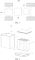
- Fig. 2 is an exploded view of the battery 100 according to some embodiments of the present application.
- the battery 100 includes a case 10 and a battery unit 20.
- the battery unit 20 is accommodated in the case 10.
- the case 10 is configured to provide an accommodation space for the battery unit 20, and the case 10 may have various structures.
- the case 10 may include a first portion 11 and a second portion 12. The first portion 11 and the second portion 12 are fitted to each other in a covered manner, and the first portion 11 and the second portion 12 jointly define the accommodation space for accommodating the battery unit 20.
- the second portion 12 may be of a hollow structure with one end open, the first portion 11 may be of a plate-like structure, and the first portion 11 covers an open side of the second portion 12 such that the first portion 11 and the second portion 12 jointly define the accommodation space; and the first portion 11 and the second portion 12 may also be of a hollow structure with one side open, and an open side of the first portion 11 covers the open side of the second portion 12.
- the case 10 formed by the first portion 11 and the second portion 12 may be in various shapes, such as a cylinder, a cuboid, etc.
- a plurality of battery units 20 may be provided.
- the plurality of battery units 20 may be connected in series, in parallel, or in series and parallel.
- the parallel-series connection means that the plurality of battery units 20 are connected both in series and in parallel.
- the plurality of battery units 20 may be directly connected together in series, or in parallel, or in series-parallel, and then a whole body composed of the plurality of battery units 20 is accommodated in the case 10; of course, the battery 100 may also be in the form that a plurality of battery units 20 are firstly connected in series or in parallel or in series and parallel to form a battery module, and then a plurality of battery modules are connected in series or in parallel or in series and parallel to form a whole and are accommodated in the case 10.
- the battery 100 may further include other structures.
- the battery 100 may further include a busbar component for achieving electric connection between the plurality of battery units 20.
- Each battery unit 20 may be a secondary battery or a primary battery, and may also be a lithium-sulfur battery, a sodium-ion battery, or a magnesium-ion battery, but is not limited thereto.
- the battery unit 20 may be in the shape of a cylinder, a flat body, a cuboid, etc.
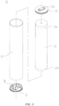
- Fig. 3 is a schematic exploded structural diagram of a battery unit 20 according to some embodiments of the present application.
- the battery unit 20 refers to the smallest unit of the battery.
- the battery unit 20 includes an end cap 21, a housing 22, an electrode assembly 23 and other functional components.
- the end cap 21 refers to a component that covers an opening of the housing 22 to isolate an internal environment of the battery unit 20 from an external environment.
- the end cap 21 may be shaped to adapt to the shape of the housing 22 so as to fit with the housing 22.
- the end cap 21 may be made of a material (e.g., an aluminum alloy) with certain hardness and strength, and thus the end cap 21 is not easily deformed when being compressed or collided, so that the battery unit 20 can have higher structural strength, and the safety performance can also be improved.
- Functional components such as an electrode terminal 21a, may be provided on the end cap 21.
- the electrode terminal 21a may be configured for electrical connection to the electrode assembly 23 for outputting or inputting electric energy of the battery unit 20.
- a pressure relief mechanism which is configured to release an internal pressure when the internal pressure or temperature of the battery unit 20 reaches a threshold, may be further provided on the end cap 21.
- the end cap 21 may also be made of various materials, such as copper, iron, aluminum, stainless steel, an aluminum alloy and plastic, which is not particularly limited in the embodiments of the present application.
- an insulating member may be further provided on an inner side of the end cap 21. The insulating member may be used to isolate electrical connection components within the housing 22 from the end cap 21 so as to reduce the risk of short circuiting.
- the insulating member may be made of plastic, rubber, etc.
- the housing 22 is an assembly that is configured to fit with the end cap 21 so as to form the internal environment of the battery unit 20, wherein the formed internal environment may be used for accommodating the electrode assembly 23, an electrolytic solution and other components.
- the housing 22 and the end cap 21 may be separate components, and the housing 22 may be provided with an opening, at which the end cap 21 covers the opening to form the internal environment of the battery unit 20.
- the end cap 21 and the housing 22 may also be integrated. Specifically, the end cap 21 and the housing 22 may firstly form a common connecting surface before other components are placed into the housing, and then the end cap 21 covers the housing 22 when the interior of the housing 22 needs to be packaged.
- the housing 22 may be in various shapes and various sizes, for example, in the shape of a cuboid, a cylinder, a hexagonal prism, etc. Specifically, the shape of the housing 22 may be determined according to the specific shape and size of the electrode assembly 23.
- the housing 22 may be made of various materials, such as copper, iron, aluminum, stainless steel, an aluminum alloy, plastic, etc., which is not particularly limited in the embodiments of the present application.
- the electrode assembly 23 is a component, where an electrochemical reaction occurs, in the battery unit 100.
- the housing 22 may include one or more electrode assemblies 23 therein.
- the electrode assembly 23 is mainly formed by winding or stacking a positive electrode plate and a negative electrode plate, and a separator (isolation film) is generally provided between the positive electrode plate and the negative electrode plate.
- the portions of the positive electrode plate and the negative electrode plate that each have an active material constitute a main body portion of the electrode assembly 23, and the portions of the positive electrode plate and the negative electrode plate that have no active material each constitute a tab 23a.
- a positive tab and a negative tab may be both located at one end of the main body portion or respectively at two ends of the main body portion.
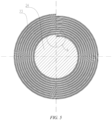
- Fig. 4 is a schematic structural diagram of the electrode assembly 23 according to some embodiments of the present application
- Fig. 5 is a schematic cross-sectional structural diagram of the electrodes assembly 23 according to some embodiments of the present application
- Fig. 6 is an enlarged schematic structural diagram of part A of the electrode assembly 23 shown in Fig. 5
- Fig. 7 is a schematic cross-sectional structural diagram of the electrode assembly 23 according to other embodiments of the present application
- Fig. 8 is an enlarged schematic structural diagram of part B of the electrode assembly shown in Fig. 7
- Fig. 9 is a schematic cross-sectional structural diagram of a support component 24 according to some embodiments of the present application
- Fig. 10 is a schematic exploded cross-sectional diagram of the support component 24 shown in Fig. 9 .
- the battery unit 20 includes: an electrode assembly 23, including a positive electrode plate 232 and a negative electrode plate 231 that have opposite polarities, and a separator 233 for separating the positive electrode plate 232 and the negative electrode plate 231; a support component 24, the electrode assembly 23 being wound around an outer periphery of the support component 24.
- An outer peripheral wall surface of the support component 24 includes a first circular arc surface 24a and a second circular arc surface 24b, one end 241 of the first circular arc surface 24a is connected to one end 241 of the second circular arc surface 24b, and the other end 242 of the first circular arc surface 24a is spaced apart from the other end 242 of the second circular arc surface 24b so as to form a step region 24c on the outer peripheral wall surface, the step region 24c being used for accommodating at least part of the electrode assembly 23.
- the first circular arc surface 24a and the second circular arc surface 24b mentioned in the present application should be understood as a surface whose cross-sectional shape is configured as a circular arc, and the circular arc may be an equal-diameter circular arc or a variable-diameter circular arc.
- the variable-diameter circular arc mentioned in the present application should be understood as an arc with a gradually varied radius.
- the spaced arrangement of the other end 242 of the first circular arc surface 24a and the other end of the second circular arc surface 24b mentioned in the present application means that the other end 242 of the first circular arc surface 24a and the other end 242 of the second circular arc surface 24b are connected in a high-low misplaced manner, and a recess formed by the misplacement is a step region 24c.
- the step region 24c mentioned in the present application is formed by the second circular arc surface 24b. It should be understood that the step region 24c mentioned in the present application extends in an axial direction of the support component 24 and throughout the entire support component 24.
- the step region 24c accommodating at least part of the electrode assembly 23 in the present application may refer to that: in the electrode assembly 23 of some embodiments as shown in Figs. 5 and 6 , the step region 24c is used for accommodating a winding starting end of the electrode assembly 23 composed of the separator 233, the positive electrode plate 232 and the negative electrode plate 231; or in the electrode assembly 23 of other embodiments as shown in Figs.
- the winding starting end of one separator 233 is located in the step region 24c and is wound around the support component 24 for at least one turn, and a winding starting end of the positive electrode plate 232, a winding starting end of the other separator 233 and a winding starting end of the negative electrode plate 231 are then accommodated in the step region 24c again to be wound around the support component 24.
- the electrode assembly 23 when the electrode assembly 23 is wound along an outer peripheral wall of the support component 24, the electrode assembly 23 may be placed in the step region 24c on the support component 24 for winding, and the step region 24c is configured such that the recess can accommodate the electrode assembly 23.
- the step region 24c formed on the outer peripheral wall surface of the support component 24 accommodates part of the electrode assembly 23, and can effectively reduce compression of the support component 24 against the winding starting end of the electrode assembly 23, thereby reducing the risk of stress concentration between the support component 24 and the electrode assembly 23.
- the other end 242 of the first circular arc surface 24a and the other end 242 of the second circular arc surface 24b are spaced apart in a radial direction d of the support component 24 to form the step region 24c.
- the other end 242 of the first circular arc surface 24a and the other end 242 of the second circular arc surface 24b are spaced apart in the radial direction d of the support component 24, so that a connecting surface for the other end 242 of the first circular arc surface 24a and the other end 242 of the second circular arc surface 24b is a radial surface, and the radial surface generally refers to a surface perpendicular to a tangential direction at the radius, and this arrangement facilitates the machining of the step region 24c.
- a central angle ⁇ corresponding to the second circular arc surface 24b may be in a range of 10° to 180°.
- the central angle ⁇ mentioned in the present application should be understood as an included angle formed by the radii at two ends of the circular arc surface.
- the sum of the central angle ⁇ of the second circular arc surface 24b and a central angle ⁇ of the first circular arc surface 24a should be 360°.
- setting the central angle ⁇ of the second circular arc surface 24b in the range of 10° to 180° can be more suitable for the winding of the electrode assembly 23, and meanwhile, it can be more conducive to accommodating the winding starting end in the step region 24c.
- the first circular arc surface 24a may be configured as an equal-diameter circular arc surface
- the second circular arc surface 24b may be configured as a variable-diameter circular arc surface
- the first circular arc surface 24a includes a first end portion 2411 and a second end portion 2421 (as shown in Fig. 10 )
- the second circular arc surface 24b includes a third end portion 2412 and a fourth end portion 2422, the first end portion 2411 and the third end portion 2412 are connected, and the second end portion 2421 and the fourth end portion 2422 are spaced apart.
- the first end portion 2411 and the third end portion 2412 have an equal diameter, and the diameter of the fourth end portion 2422 is smaller than the diameter of the second end portion 2421.
- variable-diameter circular arc surface mentioned in the present application should be understood as that the radius gradually changes from the third end portion 2412 to the fourth end portion 2422, typically a cross-sectional line of the variable-diameter circular arc surface approximates a spiral line.
- a variable-diameter parameter of the variable-diameter circular arc surface can be flexibly set in combination with the specific structural condition of the electrode assembly 23, so that the step region 24c can be adapted to the winding of the electrode assembly under different conditions, and a structural design of the step region 24c can be more flexible and diverse.
- the second circular arc surface 24b may be configured as an elliptical surface.
- the elliptical surface mentioned in the present application may refer to a partially elliptical surface, such as an elliptical surface having a central angle ⁇ ranging from 10° to 180°.
- the second circular arc surface 24b can have a larger central angle ⁇ , and thus can have a larger range of the step region 24c. In this way, more electrode assemblies 23 can be accommodated by means of the larger range of the step region 24c to further reduce the risk that the support component 24 and the electrode assembly 23 generate stress concentration.
- first circular arc surface 24a and the second circular arc surface 24b may be configured as equal-diameter circular arc surfaces, and the diameter of the first circular arc surface 24a is greater than the diameter of the second circular arc surface 24b.
- the equal-diameter circular arc surfaces mentioned in the present application mean that the radii of the circular arc surfaces are equal.
- the diameter difference between the first circular arc surface 24a and the second circular arc surface 24b in the present application may be understood as that the outer peripheral wall surface of the support component 24 is formed by connecting circular arc surfaces having different radius sizes.
- the connecting surface for the second end portion 2421 and the fourth end portion 2422 is a radial surface
- the central angle ⁇ of the second circular arc surface 24b is generally 180°.
- the step region 24c may be formed in a variety of ways, and the structural design may be flexible and diverse.
- the two separators 233, the positive electrode plate 232 and the negative electrode plate 231 have a thickness E, and the step region 24c has a depth H, wherein 0.8 ⁇ H/E ⁇ 1.2.
- the thickness mentioned in the present application refers to the sum of the thickness of the two separators 233, the thickness of the positive electrode plate 232 and the thickness of the negative electrode plate 231.
- the depth H mentioned in the present application refers to a distance between the second end portion 2421 of the first circular arc surface 24a and the fourth end portion 2422 of the second circular arc surface 24b.
- the separator 233, the positive electrode plate 232, the separator 233 and the negative electrode plate 231 are sequentially stacked and wound to form the electrode assembly 23, and the winding starting ends of the two separators 233, the winding starting end of the positive electrode plate 232 and the winding starting end of the negative electrode plate 231 are located in the step region 24c.
- the winding starting ends of the two separators 233, the winding starting end of the positive electrode plate 232 and the winding starting end of the negative electrode plate 231 mentioned in the present application may be understood as the winding starting end 234 of the electrode assembly 23 described above (as shown in Fig. 6 ).
- the winding starting end 234 is placed in the step region 24c on the support component 24, and the recess formed by the step region 24c can accommodate part of the winding starting end 234.
- a step formed by the winding starting end 234 is an important reason for the support component 24 to generate stress concentration in the prior art.
- the winding starting end 234 in the step region 24c, it is possible not only to effectively reduce the risk that the support component 24 and part of the winding starting end 234 generate stress concentration, but also to narrow the range of the step region 24, that is, the central angle ⁇ of the second circular arc surface 24b can be decreased, so that the overall structural strength of the support component 24 can be improved.
- the support component 24 may be configured as a solid structure so as to increase its overall structural strength. Referring to Fig. 11 , in other embodiments, the support component 24 may also be configured as a hollow structure so as to decrease the weight of the support component 24.
- the height of the support component 24 in the present application is equal to the height of the electrode assembly 23.
- the wall thickness of the support component 24 may range from 0.1 mm to 100 mm.
- the material of the support component 24 may be stainless steel so as to further improve its overall structural strength.
- the outer peripheral wall surface of the support component 24 may be provided with an insulating layer, and the material of the insulating layer may be polytetrafluoroethylene or asphalt, so that the support component 24 has an insulating property. In other embodiments, the material of the support component 24 may also be polytetrafluoroethylene.
- Fig. 2 is an exploded view of the battery 100 according to some embodiments of the present application.
- the battery 100 includes: a battery unit 20 of any one of the embodiments described above.
- Fig. 1 is a schematic structural diagram of a vehicle 1000 according to some embodiments of the present application.
- the present application provides a power consuming device, such as the vehicle 1000 as described above.
- the power consuming device includes the battery 100 described above, the battery 100 being used for supplying electric energy.
Landscapes
- Chemical & Material Sciences (AREA)
- Chemical Kinetics & Catalysis (AREA)
- Electrochemistry (AREA)
- General Chemical & Material Sciences (AREA)
- Engineering & Computer Science (AREA)
- Manufacturing & Machinery (AREA)
- Secondary Cells (AREA)
Abstract
Description
- The present application claims the priority of
Chinese patent application no. 202122403542.1, entitled "BATTERY UNIT, BATTERY, AND POWER CONSUMING DEVICE" and filed on September 30, 2021 - The present application relates to the technical field of batteries, and more particularly to a battery unit, a battery, and a power consuming device.
- Achieving energy conservation and emission reduction is the key to the sustainable development of the automotive industry. Electric vehicles have become an important part of the sustainable development of the automotive industry due to their advantages in energy conservation and environmental protection. For the electric vehicles, the battery technology is an important factor to their development.
- In the development of the battery technology, the service life and safety are also non-negligible issues, in addition to improving the performance of batteries. If the service life of the batteries does not reach the expected time, the maintenance and use costs of the batteries will be considerable. If the safety of the batteries cannot be guaranteed, the batteries cannot be used. Therefore, how to prolong the service life of the batteries and enhance the safety of the batteries is an urgent technical problem to be solved in the battery technology.
- In view of the above problems, the present application provides a battery unit, a battery and a power consuming device, in order to prolong the service life of the battery and enhance the safety of the battery.
- In a first aspect, the present application provides a battery unit, comprising: an electrode assembly comprising a positive electrode plate and a negative electrode plate that have opposite polarities, and a separator for separating the positive electrode plate and the negative electrode plate; and a support component, the electrode assembly being wound around an outer periphery of the support component; wherein an outer peripheral wall surface of the support component comprises a first circular arc surface and a second circular arc surface, one end of the first circular arc surface is connected to one end of the second circular arc surface, and the other end of the first circular arc surface is spaced apart from the other end of the second circular arc surface so as to form a step region on the outer peripheral wall surface, the step region being used for accommodating at least part of the electrode assembly.
- In the embodiment, the step region formed on the outer peripheral wall surface of the support component can accommodate part of the electrode assembly, and can effectively reduce compression of the support component against a winding starting end of the electrode assembly, thereby reducing the risk of stress concentration between the support component and the electrode assembly. In this way, it is possible to effectively reduce, when the battery unit expands during use, the occurrence of the problem of falling off of an active material on the electrode plates due to the compression, thereby reducing deterioration of the performance of the battery unit, effectively prolonging the service life of the battery unit, and improving the safety of the battery unit.
- In some embodiments, the other end of the first circular arc surface is spaced apart from the other end of the second circular arc surface in a radial direction of the support component to form the step region.
- In the embodiment, a connecting surface for the other end of the first circular arc surface and the other end of the second circular arc surface is a radial surface, and such an arrangement facilitates the machining of the step region.
- In some embodiments, a central angle corresponding to the second circular arc surface is in a range of 10° to 180°.
- In the embodiment, setting the central angle corresponding to the second circular arc surface in the range of 10° to 180° can be more suitable for the winding of the electrode assembly, and meanwhile, it can be more conducive to accommodating the winding starting end in the step region.
- In some embodiments, the first circular arc surface is configured as an equal-diameter circular arc surface, the second circular arc surface is configured as a variable-diameter circular arc surface, the first circular arc surface includes a first end portion and a second end portion, the second circular arc surface includes a third end portion and a fourth end portion, the first end portion and the third end portion are connected, and the second end portion and the fourth end portion are spaced apart; wherein the first end portion and the third end portion have an equal diameter, and the diameter of the fourth end portion is smaller than the diameter of the second end portion.
- In the embodiment, by configuring the second circular arc surface as the variable-diameter circular arc surface, a variable-diameter parameter of the variable-diameter circular arc surface can be flexibly set in combination with the specific structural condition of the electrode assembly, so that the step region can be adapted to the winding of the electrode assembly under different conditions, and a structural design of the step region can be flexible and diverse.
- In some embodiments, the second circular arc surface is configured as an elliptical surface.
- In the embodiment, by configuring the second circular arc surface as the elliptical surface, the second circular arc surface can have a larger central angle, and thus it is possible to have a larger range of the step region. In this way, more electrode assemblies can be accommodated by means of the larger range of the step region to further reduce the risk that the support component and the electrode assembly generate stress concentration.
- In some embodiments, the first circular arc surface and the second circular arc surface are configured as equal-diameter circular arc surfaces, and the diameter of the first circular arc surface is greater than the diameter of the second circular arc surface.
- In the embodiment, an outer surface of the support component is composed of two equal-diameter circular arc surfaces, so that the step region can be formed in a variety of ways, and the structural design can be flexible and diverse.
- In some embodiments, two separators, the positive electrode plate and the negative electrode plate have a thickness E, and the step region has a depth H, wherein 0.8 ≤ H/E ≤ 1.2.
- In the embodiment, by setting the depth of the step region to be 0.8 to 1.2 times of the thickness of the two separators, the positive electrode plate and the negative electrode plate, it is possible to better accommodate the winding starting end of the electrode assembly, reducing the risk that the support component and the electrode assembly generate stress concentration.
- In some embodiments, the separator, the positive electrode plate, the separator and the negative electrode plate are sequentially stacked and wound to form the electrode assembly, and winding starting ends of the two separators, a winding starting end of the positive electrode plate and a winding starting end of the negative electrode plate are located in the step region.
- In the embodiment, by accommodating the winding starting ends in the step region, it is possible not only to effectively reduce the risk that the support component and part of the winding starting ends generate stress concentration, but also to narrow the range of the step region, that is, the central angle of the second circular arc surface can be decreased, thereby improving the overall structural strength of the support component.
- In a second aspect, the present application provides a battery, comprising a battery unit of any one of the embodiments described above.
- In a third aspect, the present application provides a power consuming device, comprising a battery unit of any one of the embodiments described above.
- The aforementioned description is only an overview of the technical solutions of the present application. In order to more clearly understand the technical means of the present application to implement same according to the contents of the specification, and in order to make the aforementioned and other objects, features and advantages of the present application more obvious and understandable, specific embodiments of the present application are exemplarily described below.
- Various other advantages and benefits will become apparent to those of ordinary skill in the art upon reading the following detailed description of preferred embodiments. The drawings are merely for the purpose of illustrating the preferred embodiments and are not to be construed as limiting the present application. Moreover, like components are denoted by like reference numerals throughout the drawings. In the drawings:
-
Fig. 1 is a schematic structural diagram of a vehicle according to some embodiments of the present application; -
Fig. 2 is a schematic exploded structural diagram of a battery according to some embodiments of the present application; -
Fig. 3 is a schematic exploded structural diagram of a battery unit according to some embodiments of the present application; -
Fig. 4 is a schematic structural diagram of an electrode assembly according to some embodiments of the present application; -
Fig. 5 is a schematic cross-sectional structural diagram of an electrode assembly according to some embodiments of the present application; -
Fig. 6 is an enlarged schematic structural diagram of part A of the electrode assembly shown inFig. 5 ; -
Fig. 7 is a schematic cross-sectional structural diagram of an electrode assembly according to other embodiments of the present application; -
Fig. 8 is an enlarged schematic structural diagram of part B of the electrode assembly shown inFig. 7 ; -
Fig. 9 is a schematic cross-sectional structural diagram of a support component according to some embodiments of the present application; -
Fig. 10 is a schematic exploded cross-sectional diagram of the support component shown inFig. 9 ; -
Fig. 11 is a schematic cross-sectional structural diagram of a support component according to other embodiments of the present application; - In the accompanying drawings, the figures are not drawn to scale.
- The implementations of the present application will be further described in detail below in conjunction with the accompanying drawings and embodiments. The following detailed description of the embodiments and the accompanying drawings are used to illustrate the principle of the present application by way of example but should not be used to limit the scope of the present application. That is, the present application is not limited to the described embodiments.
- Unless otherwise defined, all technical and scientific terms used herein have the same meanings as those commonly understood by those skilled in the art to which the present application belongs. The terms used herein are merely for the purpose of describing specific embodiments, but are not intended to limit the present application. The terms "comprising" and "including" and any variations thereof in the description and the claims of the present application as well as the brief description of the accompanying drawings described above are intended to cover non-exclusive inclusion.
- In the description of the embodiments of the present application, the technical terms "first", "second", etc. are merely used for distinguishing different objects, and are not to be construed as indicating or implying relative importance or implicitly indicating the number, particular order or primary-secondary relationship of the technical features modified thereby. In the description of the embodiments of the present application, the phrase "a plurality of' means two or more, unless otherwise explicitly and specifically defined.
- The phrase "embodiment" mentioned herein means that the specific features, structures, or characteristics described in conjunction with the embodiment can be encompassed in at least one embodiment of the present application. The phrase at various locations in the description does not necessarily refer to the same embodiment, or an independent or alternative embodiment exclusive of another embodiment. Those skilled in the art understand explicitly or implicitly that the embodiment described herein may be combined with another embodiment.
- In the description of the embodiments of the present application, the term "and/or" is merely intended to describe the associated relationship of associated objects, indicating that three relationships can exist, for example, A and/or B can include: the three instances of A alone, A and B simultaneously, and B alone. In addition, the character "j" herein generally indicates an "or" relationship between the associated objects.
- In the description of the embodiments of the present application, the term "a plurality of' means two or more (including two), similarly the term "a plurality of groups" means two or more groups (including two groups), and the term "a plurality of pieces" means two or more pieces (including two pieces).
- In the description of the embodiments of the present application, the orientation or position relationship indicated by the technical terms "central", "longitudinal", "transverse", "length", "width", "thickness", "upper", "lower", "front"; "rear", "left", "right", "vertical", "horizontal", "top", "bottom", "inner", "outer", "clockwise", "counterclockwise", "axial", "radial", "circumferential", etc. are based on the orientation or position relationship shown in the drawings and are merely intended to facilitate and simplify the description of the embodiments of the present application, rather than indicating or implying that the device or element considered must have a particular orientation or be constructed and operated in a particular orientation, and therefore not to be construed as limiting the embodiments of the present application.
- In the description of the embodiments of the present application, unless otherwise explicitly specified and defined, the technical terms "mounting", "mutual connection", "connection", "fixing", etc. should be understood in a broad sense, for example, they may be a fixed connection, a detachable connection, or an integrated connection; may be a mechanical connection or an electrical connection; and may be a direct connection or an indirect connection through an intermediate medium, and may be communication between interiors of two elements or interaction between the two elements. For those of ordinary skill in the art, the specific meaning of the above terms in the embodiments of the present application can be understood according to specific situations.
- At present, from the perspective of the development of the market situation, the traction batteries are used more and more widely. The traction batteries are not only used in energy storage power systems such as hydroelectric power plants, thermal power plants, wind power plants and solar power plants, but also widely used in electric transportation means such as electric bicycles, electric motorcycles and electric vehicles and in many fields such as military equipment and aerospace. With the continuous expansion of the application field of traction batteries, the market demand for the traction batteries is also expanding.
- The applicant has noted that a support component is generally a cylindrical body having the same diameter at each part, an electrode assembly is wound around an outer periphery of the support component, and a winding starting end of the electrode assembly and an outer peripheral wall surface of the support component form a step; however, a battery unit (also called a cell) generally expands during use, and the support component compresses the winding starting end of the electrode assembly. The compression may cause an active material on an electrode plate to fall off, thereby deteriorating the performance of the battery unit, and in severe cases, a separator may be punctured, causing short circuiting of the battery, and thus resulting in a safety problem. As the mileage of an automobile and the energy density of the battery increase, the demand for an electrode plate with a large coating weight is growing, that is to say, the electrode plate with a large coating weight increases the height of the step, and the compression of the support component against an electrode assembly is increasingly serious.
- On the basis of the above consideration, in order to solve the problem that the performance of a battery unit deteriorates due to the expansibility of the battery unit during the use of the battery unit, after intensive research, a battery unit is designed, and the step at the time of winding the electrode assembly can be accommodated in a step region by forming a step region on an outer peripheral wall surface of the support component (equivalent to a center pin in the prior art) of the battery unit, thereby avoiding the compression.
- The battery unit disclosed in the embodiments of the present application may be used in, but not limited to, a power consuming device, such as a vehicle, a ship, or an aircraft. A power supply system provided with the power consuming device composed of a battery unit, a battery and the like disclosed in the present application may be used.
- The embodiments of the present application provide a power consuming device using a battery as a power supply. The power consuming device may be, but is not limited to, a mobile phone, a tablet, a laptop, an electric toy, an electric tool, a battery cart, an electric vehicle, a ship, a spacecraft, etc. The electric toy may include a stationary or mobile electric toy, for example, a game console, an electric vehicle toy, an electric ship toy, an electric airplane toy, etc. The spacecraft may include an airplane, a rocket, a space shuttle, a spaceship, etc.
- For ease of description of the following embodiments, an embodiment of the present application in which the power consuming device is a
vehicle 1000 is taken as an example for description. - Referring to
Fig. 1, Fig. 1 is a schematic structural diagram of avehicle 1000 according to some embodiments of the present application. Thevehicle 1000 may be a fuel vehicle, a gas vehicle, or a new energy vehicle. The new energy vehicle may be a battery electric vehicle, a hybrid electric vehicle, an extended-range vehicle, etc. Abattery 100 is provided inside thevehicle 1000, and thebattery 100 may be provided at the bottom, the front or the back of thevehicle 1000. Thebattery 100 may be configured to supply power to thevehicle 1000. For example, thebattery 100 may be used as a power supply for operating thevehicle 1000. Thevehicle 1000 may further include acontroller 200 and amotor 300. Thecontroller 200 is configured to control thebattery 100 to supply power to themotor 300, for example, to meet working power requirements during starting, navigation and traveling of thevehicle 1000. - In some embodiments of the present application, the
battery 100 can not only serve as a power supply for operating thevehicle 1000, but also serve as a power supply for driving thevehicle 1000, instead of or partially instead of fuel or natural gas, to provide driving power to thevehicle 1000. - Referring to
Fig. 2, Fig. 2 is an exploded view of thebattery 100 according to some embodiments of the present application. Thebattery 100 includes acase 10 and abattery unit 20. Thebattery unit 20 is accommodated in thecase 10. Thecase 10 is configured to provide an accommodation space for thebattery unit 20, and thecase 10 may have various structures. In some embodiments, thecase 10 may include afirst portion 11 and asecond portion 12. Thefirst portion 11 and thesecond portion 12 are fitted to each other in a covered manner, and thefirst portion 11 and thesecond portion 12 jointly define the accommodation space for accommodating thebattery unit 20. Thesecond portion 12 may be of a hollow structure with one end open, thefirst portion 11 may be of a plate-like structure, and thefirst portion 11 covers an open side of thesecond portion 12 such that thefirst portion 11 and thesecond portion 12 jointly define the accommodation space; and thefirst portion 11 and thesecond portion 12 may also be of a hollow structure with one side open, and an open side of thefirst portion 11 covers the open side of thesecond portion 12. Of course, thecase 10 formed by thefirst portion 11 and thesecond portion 12 may be in various shapes, such as a cylinder, a cuboid, etc. - In the
battery 100, a plurality ofbattery units 20 may be provided. The plurality ofbattery units 20 may be connected in series, in parallel, or in series and parallel. The parallel-series connection means that the plurality ofbattery units 20 are connected both in series and in parallel. The plurality ofbattery units 20 may be directly connected together in series, or in parallel, or in series-parallel, and then a whole body composed of the plurality ofbattery units 20 is accommodated in thecase 10; of course, thebattery 100 may also be in the form that a plurality ofbattery units 20 are firstly connected in series or in parallel or in series and parallel to form a battery module, and then a plurality of battery modules are connected in series or in parallel or in series and parallel to form a whole and are accommodated in thecase 10. Thebattery 100 may further include other structures. For example, thebattery 100 may further include a busbar component for achieving electric connection between the plurality ofbattery units 20. - Each
battery unit 20 may be a secondary battery or a primary battery, and may also be a lithium-sulfur battery, a sodium-ion battery, or a magnesium-ion battery, but is not limited thereto. Thebattery unit 20 may be in the shape of a cylinder, a flat body, a cuboid, etc. - Referring to
Fig. 3, Fig. 3 is a schematic exploded structural diagram of abattery unit 20 according to some embodiments of the present application. Thebattery unit 20 refers to the smallest unit of the battery. As shown inFig. 3 , thebattery unit 20 includes anend cap 21, ahousing 22, anelectrode assembly 23 and other functional components. - The
end cap 21 refers to a component that covers an opening of thehousing 22 to isolate an internal environment of thebattery unit 20 from an external environment. Without limitation, theend cap 21 may be shaped to adapt to the shape of thehousing 22 so as to fit with thehousing 22. Optionally, theend cap 21 may be made of a material (e.g., an aluminum alloy) with certain hardness and strength, and thus theend cap 21 is not easily deformed when being compressed or collided, so that thebattery unit 20 can have higher structural strength, and the safety performance can also be improved. Functional components, such as anelectrode terminal 21a, may be provided on theend cap 21. Theelectrode terminal 21a may be configured for electrical connection to theelectrode assembly 23 for outputting or inputting electric energy of thebattery unit 20. In some embodiments, a pressure relief mechanism, which is configured to release an internal pressure when the internal pressure or temperature of thebattery unit 20 reaches a threshold, may be further provided on theend cap 21. Theend cap 21 may also be made of various materials, such as copper, iron, aluminum, stainless steel, an aluminum alloy and plastic, which is not particularly limited in the embodiments of the present application. In some embodiments, an insulating member may be further provided on an inner side of theend cap 21. The insulating member may be used to isolate electrical connection components within thehousing 22 from theend cap 21 so as to reduce the risk of short circuiting. Exemplarily, the insulating member may be made of plastic, rubber, etc. - The
housing 22 is an assembly that is configured to fit with theend cap 21 so as to form the internal environment of thebattery unit 20, wherein the formed internal environment may be used for accommodating theelectrode assembly 23, an electrolytic solution and other components. Thehousing 22 and theend cap 21 may be separate components, and thehousing 22 may be provided with an opening, at which theend cap 21 covers the opening to form the internal environment of thebattery unit 20. Without limitation, theend cap 21 and thehousing 22 may also be integrated. Specifically, theend cap 21 and thehousing 22 may firstly form a common connecting surface before other components are placed into the housing, and then theend cap 21 covers thehousing 22 when the interior of thehousing 22 needs to be packaged. Thehousing 22 may be in various shapes and various sizes, for example, in the shape of a cuboid, a cylinder, a hexagonal prism, etc. Specifically, the shape of thehousing 22 may be determined according to the specific shape and size of theelectrode assembly 23. Thehousing 22 may be made of various materials, such as copper, iron, aluminum, stainless steel, an aluminum alloy, plastic, etc., which is not particularly limited in the embodiments of the present application. - The
electrode assembly 23 is a component, where an electrochemical reaction occurs, in thebattery unit 100. Thehousing 22 may include one ormore electrode assemblies 23 therein. Theelectrode assembly 23 is mainly formed by winding or stacking a positive electrode plate and a negative electrode plate, and a separator (isolation film) is generally provided between the positive electrode plate and the negative electrode plate. The portions of the positive electrode plate and the negative electrode plate that each have an active material constitute a main body portion of theelectrode assembly 23, and the portions of the positive electrode plate and the negative electrode plate that have no active material each constitute a tab 23a. A positive tab and a negative tab may be both located at one end of the main body portion or respectively at two ends of the main body portion. During the charge/discharge process of the battery, a positive electrode active material and a negative electrode active material react with the electrolytic solution, and the tabs 23a are connected to the electrode terminals to form a current loop. - Referring to
Figs. 4 to 9 ,Fig. 4 is a schematic structural diagram of theelectrode assembly 23 according to some embodiments of the present application;Fig. 5 is a schematic cross-sectional structural diagram of theelectrodes assembly 23 according to some embodiments of the present application;Fig. 6 is an enlarged schematic structural diagram of part A of theelectrode assembly 23 shown inFig. 5 ;Fig. 7 is a schematic cross-sectional structural diagram of theelectrode assembly 23 according to other embodiments of the present application;Fig. 8 is an enlarged schematic structural diagram of part B of the electrode assembly shown inFig. 7 ;Fig. 9 is a schematic cross-sectional structural diagram of asupport component 24 according to some embodiments of the present application; andFig. 10 is a schematic exploded cross-sectional diagram of thesupport component 24 shown inFig. 9 . - The
battery unit 20 according to the present application includes: anelectrode assembly 23, including apositive electrode plate 232 and anegative electrode plate 231 that have opposite polarities, and aseparator 233 for separating thepositive electrode plate 232 and thenegative electrode plate 231; asupport component 24, theelectrode assembly 23 being wound around an outer periphery of thesupport component 24. An outer peripheral wall surface of thesupport component 24 includes a firstcircular arc surface 24a and a secondcircular arc surface 24b, oneend 241 of the firstcircular arc surface 24a is connected to oneend 241 of the secondcircular arc surface 24b, and theother end 242 of the firstcircular arc surface 24a is spaced apart from theother end 242 of the secondcircular arc surface 24b so as to form astep region 24c on the outer peripheral wall surface, thestep region 24c being used for accommodating at least part of theelectrode assembly 23. - The first
circular arc surface 24a and the secondcircular arc surface 24b mentioned in the present application should be understood as a surface whose cross-sectional shape is configured as a circular arc, and the circular arc may be an equal-diameter circular arc or a variable-diameter circular arc. The variable-diameter circular arc mentioned in the present application should be understood as an arc with a gradually varied radius. After oneend 241 of the firstcircular arc surface 24a is connected to oneend 241 of the secondcircular arc surface 24b in the present application, the portion of the connection should be a complete circular arc surface. It can be understood that, the spaced arrangement of theother end 242 of the firstcircular arc surface 24a and the other end of the secondcircular arc surface 24b mentioned in the present application means that theother end 242 of the firstcircular arc surface 24a and theother end 242 of the secondcircular arc surface 24b are connected in a high-low misplaced manner, and a recess formed by the misplacement is astep region 24c. Thestep region 24c mentioned in the present application is formed by the secondcircular arc surface 24b. It should be understood that thestep region 24c mentioned in the present application extends in an axial direction of thesupport component 24 and throughout theentire support component 24. Thestep region 24c accommodating at least part of theelectrode assembly 23 in the present application may refer to that: in theelectrode assembly 23 of some embodiments as shown inFigs. 5 and6 , thestep region 24c is used for accommodating a winding starting end of theelectrode assembly 23 composed of theseparator 233, thepositive electrode plate 232 and thenegative electrode plate 231; or in theelectrode assembly 23 of other embodiments as shown inFigs. 7 and8 , the winding starting end of oneseparator 233 is located in thestep region 24c and is wound around thesupport component 24 for at least one turn, and a winding starting end of thepositive electrode plate 232, a winding starting end of theother separator 233 and a winding starting end of thenegative electrode plate 231 are then accommodated in thestep region 24c again to be wound around thesupport component 24. - In the
battery unit 20 of the present application, when theelectrode assembly 23 is wound along an outer peripheral wall of thesupport component 24, theelectrode assembly 23 may be placed in thestep region 24c on thesupport component 24 for winding, and thestep region 24c is configured such that the recess can accommodate theelectrode assembly 23. With such an arrangement, thestep region 24c formed on the outer peripheral wall surface of thesupport component 24 accommodates part of theelectrode assembly 23, and can effectively reduce compression of thesupport component 24 against the winding starting end of theelectrode assembly 23, thereby reducing the risk of stress concentration between thesupport component 24 and theelectrode assembly 23. In this way, it is possible to effectively reduce, when thebattery unit 20 expands during use, the occurrence of the problem of falling off of an active material on the electrode plates (thepositive electrode plate 232 and the negative electrode plate 231) due to the compression, thereby reducing deterioration of the performance of thebattery unit 20, effectively prolonging the service life of thebattery unit 20, and improving the safety of the battery unit. - Referring to
Figs. 6 ,8 , and9 , in some embodiments, theother end 242 of the firstcircular arc surface 24a and theother end 242 of the secondcircular arc surface 24b are spaced apart in a radial direction d of thesupport component 24 to form thestep region 24c. - In the present application, the
other end 242 of the firstcircular arc surface 24a and theother end 242 of the secondcircular arc surface 24b are spaced apart in the radial direction d of thesupport component 24, so that a connecting surface for theother end 242 of the firstcircular arc surface 24a and theother end 242 of the secondcircular arc surface 24b is a radial surface, and the radial surface generally refers to a surface perpendicular to a tangential direction at the radius, and this arrangement facilitates the machining of thestep region 24c. - Referring to
Fig. 9 , in some embodiments, a central angle β corresponding to the secondcircular arc surface 24b may be in a range of 10° to 180°. The central angle β mentioned in the present application should be understood as an included angle formed by the radii at two ends of the circular arc surface. The sum of the central angle β of the secondcircular arc surface 24b and a central angle α of the firstcircular arc surface 24a should be 360°. - In the present application, it can be understood that the smaller the central angle β of the second
circular arc surface 24b is, the shorter the arc length of the secondcircular arc surface 24b is, and a displacement is more likely to occur when theelectrode assembly 23 is wound around the secondcircular arc surface 24b in a fitting manner, so that the winding starting end of theelectrode assembly 23 cannot be better accommodated in thestep region 24c. In the present application, setting the central angle β of the secondcircular arc surface 24b in the range of 10° to 180° can be more suitable for the winding of theelectrode assembly 23, and meanwhile, it can be more conducive to accommodating the winding starting end in thestep region 24c. - Referring to
Figs. 9 to 11 , in some embodiments, the firstcircular arc surface 24a may be configured as an equal-diameter circular arc surface, and the secondcircular arc surface 24b may be configured as a variable-diameter circular arc surface; the firstcircular arc surface 24a includes afirst end portion 2411 and a second end portion 2421 (as shown inFig. 10 ), the secondcircular arc surface 24b includes athird end portion 2412 and afourth end portion 2422, thefirst end portion 2411 and thethird end portion 2412 are connected, and thesecond end portion 2421 and thefourth end portion 2422 are spaced apart. Thefirst end portion 2411 and thethird end portion 2412 have an equal diameter, and the diameter of thefourth end portion 2422 is smaller than the diameter of thesecond end portion 2421. - The variable-diameter circular arc surface mentioned in the present application should be understood as that the radius gradually changes from the
third end portion 2412 to thefourth end portion 2422, typically a cross-sectional line of the variable-diameter circular arc surface approximates a spiral line. In the present application, by configuring the secondcircular arc surface 24b on the outer peripheral wall of thesupport component 24 as the variable-diameter circular arc surface, a variable-diameter parameter of the variable-diameter circular arc surface can be flexibly set in combination with the specific structural condition of theelectrode assembly 23, so that thestep region 24c can be adapted to the winding of the electrode assembly under different conditions, and a structural design of thestep region 24c can be more flexible and diverse. - In other embodiments, the second
circular arc surface 24b may be configured as an elliptical surface. The elliptical surface mentioned in the present application may refer to a partially elliptical surface, such as an elliptical surface having a central angle β ranging from 10° to 180°. With the arrangement, by configuring the secondcircular arc surface 24b as the elliptical surface in the embodiment, the secondcircular arc surface 24b can have a larger central angle β, and thus can have a larger range of thestep region 24c. In this way,more electrode assemblies 23 can be accommodated by means of the larger range of thestep region 24c to further reduce the risk that thesupport component 24 and theelectrode assembly 23 generate stress concentration. - In some other embodiments, the first
circular arc surface 24a and the secondcircular arc surface 24b may be configured as equal-diameter circular arc surfaces, and the diameter of the firstcircular arc surface 24a is greater than the diameter of the secondcircular arc surface 24b. - The equal-diameter circular arc surfaces mentioned in the present application mean that the radii of the circular arc surfaces are equal. The diameter difference between the first
circular arc surface 24a and the secondcircular arc surface 24b in the present application may be understood as that the outer peripheral wall surface of thesupport component 24 is formed by connecting circular arc surfaces having different radius sizes. In order to satisfy the condition that the connecting surface for thesecond end portion 2421 and thefourth end portion 2422 is a radial surface, after the firstcircular arc surface 24a and the secondcircular arc surface 24b of the equal-diameter circular arc surface of the outer peripheral wall surface of thesupport component 24 in the embodiment are connected, the central angle β of the secondcircular arc surface 24b is generally 180°. With the arrangement, thestep region 24c may be formed in a variety of ways, and the structural design may be flexible and diverse. - Referring to
Fig. 9 , in some embodiments, the twoseparators 233, thepositive electrode plate 232 and thenegative electrode plate 231 have a thickness E, and thestep region 24c has a depth H, wherein 0.8 ≤ H/E ≤ 1.2. - The thickness mentioned in the present application refers to the sum of the thickness of the two
separators 233, the thickness of thepositive electrode plate 232 and the thickness of thenegative electrode plate 231. The depth H mentioned in the present application refers to a distance between thesecond end portion 2421 of the firstcircular arc surface 24a and thefourth end portion 2422 of the secondcircular arc surface 24b. With the arrangement, it is possible to better accommodate the winding starting end of theelectrode assembly 23 by setting the depth of thestep region 24c to be 0.8 to 1.2 times of the thickness of the twoseparators 233, thepositive electrode plate 232 and thenegative electrode plate 231 while the requirement for machining errors is met. Further, by setting H/E to be 1.2 times thereof, it is also possible to fully accommodate the winding starting end of theelectrode assembly 23, thereby eliminating the risk that thesupport component 24 and theelectrode assembly 23 generate stress concentration while the machining difficulty is reduced. - Referring to
Fig. 6 , in some embodiments, theseparator 233, thepositive electrode plate 232, theseparator 233 and thenegative electrode plate 231 are sequentially stacked and wound to form theelectrode assembly 23, and the winding starting ends of the twoseparators 233, the winding starting end of thepositive electrode plate 232 and the winding starting end of thenegative electrode plate 231 are located in thestep region 24c. - The winding starting ends of the two
separators 233, the winding starting end of thepositive electrode plate 232 and the winding starting end of thenegative electrode plate 231 mentioned in the present application may be understood as the winding startingend 234 of theelectrode assembly 23 described above (as shown inFig. 6 ). In the present application, when theelectrode assembly 23 is wound along the outer peripheral wall of thesupport component 24, the winding startingend 234 is placed in thestep region 24c on thesupport component 24, and the recess formed by thestep region 24c can accommodate part of the winding startingend 234. However, in general, a step formed by the winding startingend 234 is an important reason for thesupport component 24 to generate stress concentration in the prior art. In the present application, by accommodating the winding startingend 234 in thestep region 24c, it is possible not only to effectively reduce the risk that thesupport component 24 and part of the winding startingend 234 generate stress concentration, but also to narrow the range of thestep region 24, that is, the central angle β of the secondcircular arc surface 24b can be decreased, so that the overall structural strength of thesupport component 24 can be improved. - In some embodiments, the
support component 24 may be configured as a solid structure so as to increase its overall structural strength. Referring toFig. 11 , in other embodiments, thesupport component 24 may also be configured as a hollow structure so as to decrease the weight of thesupport component 24. The height of thesupport component 24 in the present application is equal to the height of theelectrode assembly 23. - In some embodiments, the wall thickness of the
support component 24 may range from 0.1 mm to 100 mm. The material of thesupport component 24 may be stainless steel so as to further improve its overall structural strength. The outer peripheral wall surface of thesupport component 24 may be provided with an insulating layer, and the material of the insulating layer may be polytetrafluoroethylene or asphalt, so that thesupport component 24 has an insulating property. In other embodiments, the material of thesupport component 24 may also be polytetrafluoroethylene. - Referring to
Fig. 2, Fig. 2 is an exploded view of thebattery 100 according to some embodiments of the present application. Thebattery 100 includes: abattery unit 20 of any one of the embodiments described above. - Referring to
Fig. 1, Fig. 1 is a schematic structural diagram of avehicle 1000 according to some embodiments of the present application. The present application provides a power consuming device, such as thevehicle 1000 as described above. The power consuming device includes thebattery 100 described above, thebattery 100 being used for supplying electric energy. - While the present application has been described with reference to the preferred embodiments, various modifications can be made, and equivalents can be provided to substitute for the components thereof without departing from the scope of the present application. In particular, the technical features mentioned in the embodiments can be combined in any manner, provided that there is no structural conflict. The present application is not limited to the specific embodiments disclosed herein but includes all the technical solutions that fall within the scope of the claims.
Claims (10)
- A battery unit, comprising:an electrode assembly comprising a positive electrode plate and a negative electrode plate that have opposite polarities, and a separator for separating the positive electrode plate and the negative electrode plate; anda support component, the electrode assembly being wound around an outer periphery of the support component;wherein an outer peripheral wall surface of the support component comprises a first circular arc surface and a second circular arc surface, one end of the first circular arc surface is connected to one end of the second circular arc surface, and the other end of the first circular arc surface is spaced apart from the other end of the second circular arc surface so as to form a step region on the outer peripheral wall surface, the step region being used for accommodating at least part of the electrode assembly.
- The battery unit of claim 1, wherein the other end of the first circular arc surface is spaced apart from the other end of the second circular arc surface in a radial direction of the support component to form the step region.
- The battery unit of claim 1 or 2, wherein a central angle corresponding to the second circular arc surface is in a range of 10° to 180°.
- The battery unit of claim 1 or 2, wherein the first circular arc surface is configured as an equal-diameter circular arc surface, the second circular arc surface is configured as a variable-diameter circular arc surface, the first circular arc surface comprises a first end portion and a second end portion, the second circular arc surface comprises a third end portion and a fourth end portion, the first end portion and the third end portion are connected, and the second end portion and the fourth end portion are spaced apart, wherein the first end portion and the third end portion have an equal diameter, and the diameter of the fourth end portion is smaller than the diameter of the second end portion.
- The battery unit of claim 4, wherein the second circular arc surface is configured as an elliptical surface.
- The battery unit of claim 1 or 2, wherein the first circular arc surface and the second circular arc surface are configured as equal-diameter circular arc surfaces, and the diameter of the first circular arc surface is greater than the diameter of the second circular arc surface.
- The battery unit of claim 1 or 2, wherein two separators, the positive electrode plate and the negative electrode plate have a thickness E, and the step region has a depth H, wherein 0.8 ≤ H/E ≤ 1.2.
- The battery unit of claim 1 or 2, wherein the separator, the positive electrode plate, the separator and the negative electrode plate are sequentially stacked and wound to form the electrode assembly, and winding starting ends of the two separators, a winding starting end of the positive electrode plate and a winding starting end of the negative electrode plate are located in the step region.
- A battery, comprising: a battery unit of any one of claims 1 to 8.
- A power consuming device, comprising a battery unit of any one of claims 1 to 8.
Applications Claiming Priority (2)
| Application Number | Priority Date | Filing Date | Title |
|---|---|---|---|
| CN202122403542.1U CN215933649U (en) | 2021-09-30 | 2021-09-30 | Battery cell, battery and power consumption device |
| PCT/CN2022/105807 WO2023050977A1 (en) | 2021-09-30 | 2022-07-14 | Battery cell, battery, and power consuming device |
Publications (2)
| Publication Number | Publication Date |
|---|---|
| EP4350816A1 true EP4350816A1 (en) | 2024-04-10 |
| EP4350816A4 EP4350816A4 (en) | 2025-04-23 |
Family
ID=80407557
Family Applications (1)
| Application Number | Title | Priority Date | Filing Date |
|---|---|---|---|
| EP22874374.6A Pending EP4350816A4 (en) | 2021-09-30 | 2022-07-14 | Battery cell, battery, and power consuming device |
Country Status (4)
| Country | Link |
|---|---|
| US (1) | US20240097143A1 (en) |
| EP (1) | EP4350816A4 (en) |
| CN (1) | CN215933649U (en) |
| WO (1) | WO2023050977A1 (en) |
Families Citing this family (1)
| Publication number | Priority date | Publication date | Assignee | Title |
|---|---|---|---|---|
| CN215933649U (en) * | 2021-09-30 | 2022-03-01 | 宁德时代新能源科技股份有限公司 | Battery cell, battery and power consumption device |
Family Cites Families (9)
| Publication number | Priority date | Publication date | Assignee | Title |
|---|---|---|---|---|
| JP3611899B2 (en) * | 1995-07-14 | 2005-01-19 | 東芝電池株式会社 | Winding electrode manufacturing method and manufacturing apparatus |
| JPH11111328A (en) * | 1997-10-07 | 1999-04-23 | Toshiba Battery Co Ltd | Manufacture of wound type electrode and manufacturing device |
| JP2000164242A (en) * | 1998-11-20 | 2000-06-16 | Furukawa Battery Co Ltd:The | Manufacture of wound electrode plate group for cylindrical battery |
| JP2005310725A (en) * | 2004-04-16 | 2005-11-04 | Kaido Seisakusho:Kk | Different diameter core for winding device |
| KR101010368B1 (en) * | 2006-09-18 | 2011-01-25 | 주식회사 엘지화학 | Method for manufacturing jelly-roll type electrode assembly |
| JP4803201B2 (en) * | 2008-04-04 | 2011-10-26 | トヨタ自動車株式会社 | Winding type battery and method of manufacturing winding type battery |
| JP2011014297A (en) * | 2009-06-30 | 2011-01-20 | Panasonic Corp | Wound electrode group and battery |
| KR101671176B1 (en) * | 2014-11-05 | 2016-11-01 | 주식회사 비츠로셀 | battery of wound type for enhancing durability and stability |
| CN215933649U (en) * | 2021-09-30 | 2022-03-01 | 宁德时代新能源科技股份有限公司 | Battery cell, battery and power consumption device |
-
2021
- 2021-09-30 CN CN202122403542.1U patent/CN215933649U/en active Active
-
2022
- 2022-07-14 WO PCT/CN2022/105807 patent/WO2023050977A1/en not_active Ceased
- 2022-07-14 EP EP22874374.6A patent/EP4350816A4/en active Pending
-
2023
- 2023-11-16 US US18/511,585 patent/US20240097143A1/en active Pending
Also Published As
| Publication number | Publication date |
|---|---|
| CN215933649U (en) | 2022-03-01 |
| EP4350816A4 (en) | 2025-04-23 |
| WO2023050977A1 (en) | 2023-04-06 |
| US20240097143A1 (en) | 2024-03-21 |
Similar Documents
| Publication | Publication Date | Title |
|---|---|---|
| EP4435946A1 (en) | Battery box body, battery, electrical device, and manufacturing apparatus | |
| EP4325642A1 (en) | Case, battery and power consuming device | |
| EP4425654A1 (en) | Battery cell, battery and electric device | |
| EP4391199A1 (en) | Battery unit, battery, and electric device | |
| US20250046934A1 (en) | Battery and electric apparatus | |
| KR20250022186A (en) | Electrode assembly, battery cell, battery and electrical device | |
| WO2023207402A1 (en) | Top cap assembly, battery cell, battery and power consuming apparatus | |
| EP4401225A1 (en) | Battery casing, battery cell, battery, and electrical device | |
| CN115084733B (en) | Shell, battery cell, battery and electrical device | |
| EP4654345A1 (en) | Battery cell, battery, and electric device | |
| EP4459752A1 (en) | Battery cell, battery, and electric device | |
| US20250260147A1 (en) | Housing for battery cell, battery cell, battery, and electric device | |
| US20230361356A1 (en) | Battery unit, and battery, power consuming device and preparation apparatus associated therewith | |
| US20230238642A1 (en) | Battery cell, battery, power consuming device, and method for manufacturing battery cell | |
| US12469926B2 (en) | Battery cell, cover assembly, battery, electric apparatus, method, and device | |
| US20240097143A1 (en) | Battery unit, battery, and power consuming device | |
| EP4510371A1 (en) | Battery cell, battery, and electrical apparatus | |
| US20240379968A1 (en) | Current collector, electrode plate, electrode assembly, battery cell, battery, and electric device | |
| US20240014502A1 (en) | Battery, battery module, and electrically powered device | |
| EP4451437A1 (en) | Top cover assembly, battery cell, battery, and electrical device | |
| EP4586372A1 (en) | Battery cell, battery, electrical device and energy storage apparatus | |
| CN223401866U (en) | Battery cells, battery devices and electrical equipment | |
| EP4391200A1 (en) | Single battery, battery, and power utilization device | |
| CN118783002B (en) | Battery devices and power-consuming devices | |
| EP4618260A1 (en) | Battery cell, battery, electrical device, and energy storage apparatus |
Legal Events
| Date | Code | Title | Description |
|---|---|---|---|
| STAA | Information on the status of an ep patent application or granted ep patent |
Free format text: STATUS: THE INTERNATIONAL PUBLICATION HAS BEEN MADE |
|
| PUAI | Public reference made under article 153(3) epc to a published international application that has entered the european phase |
Free format text: ORIGINAL CODE: 0009012 |
|
| STAA | Information on the status of an ep patent application or granted ep patent |
Free format text: STATUS: REQUEST FOR EXAMINATION WAS MADE |
|
| 17P | Request for examination filed |
Effective date: 20240104 |
|
| AK | Designated contracting states |
Kind code of ref document: A1 Designated state(s): AL AT BE BG CH CY CZ DE DK EE ES FI FR GB GR HR HU IE IS IT LI LT LU LV MC MK MT NL NO PL PT RO RS SE SI SK SM TR |
|
| RAP1 | Party data changed (applicant data changed or rights of an application transferred) |
Owner name: CONTEMPORARY AMPEREX TECHNOLOGY(HONG KONG) LIMITED |
|
| DAV | Request for validation of the european patent (deleted) | ||
| DAX | Request for extension of the european patent (deleted) | ||
| A4 | Supplementary search report drawn up and despatched |
Effective date: 20250326 |
|
| RIC1 | Information provided on ipc code assigned before grant |
Ipc: H01M 50/486 20210101ALI20250320BHEP Ipc: H01M 50/477 20210101ALI20250320BHEP Ipc: H01M 50/474 20210101ALI20250320BHEP Ipc: H01M 50/107 20210101ALI20250320BHEP Ipc: H01M 50/14 20210101ALI20250320BHEP Ipc: H01M 10/0587 20100101ALI20250320BHEP Ipc: H01M 10/04 20060101ALI20250320BHEP Ipc: H01M 4/78 20060101AFI20250320BHEP |