EP4350717A1 - Dynamic submarine power cable with corrugated and smooth metallic water barrier - Google Patents
Dynamic submarine power cable with corrugated and smooth metallic water barrier Download PDFInfo
- Publication number
- EP4350717A1 EP4350717A1 EP22199612.7A EP22199612A EP4350717A1 EP 4350717 A1 EP4350717 A1 EP 4350717A1 EP 22199612 A EP22199612 A EP 22199612A EP 4350717 A1 EP4350717 A1 EP 4350717A1
- Authority
- EP
- European Patent Office
- Prior art keywords
- section
- power cable
- water blocking
- blocking layer
- metallic water
- Prior art date
- Legal status (The legal status is an assumption and is not a legal conclusion. Google has not performed a legal analysis and makes no representation as to the accuracy of the status listed.)
- Pending
Links
Images

Classifications
-
- H—ELECTRICITY
- H01—ELECTRIC ELEMENTS
- H01B—CABLES; CONDUCTORS; INSULATORS; SELECTION OF MATERIALS FOR THEIR CONDUCTIVE, INSULATING OR DIELECTRIC PROPERTIES
- H01B7/00—Insulated conductors or cables characterised by their form
- H01B7/17—Protection against damage caused by external factors, e.g. sheaths or armouring
- H01B7/28—Protection against damage caused by moisture, corrosion, chemical attack or weather
- H01B7/282—Preventing penetration of fluid, e.g. water or humidity, into conductor or cable
- H01B7/2825—Preventing penetration of fluid, e.g. water or humidity, into conductor or cable using a water impermeable sheath
-
- H—ELECTRICITY
- H01—ELECTRIC ELEMENTS
- H01B—CABLES; CONDUCTORS; INSULATORS; SELECTION OF MATERIALS FOR THEIR CONDUCTIVE, INSULATING OR DIELECTRIC PROPERTIES
- H01B7/00—Insulated conductors or cables characterised by their form
- H01B7/17—Protection against damage caused by external factors, e.g. sheaths or armouring
- H01B7/28—Protection against damage caused by moisture, corrosion, chemical attack or weather
- H01B7/282—Preventing penetration of fluid, e.g. water or humidity, into conductor or cable
-
- B—PERFORMING OPERATIONS; TRANSPORTING
- B63—SHIPS OR OTHER WATERBORNE VESSELS; RELATED EQUIPMENT
- B63B—SHIPS OR OTHER WATERBORNE VESSELS; EQUIPMENT FOR SHIPPING
- B63B35/00—Vessels or similar floating structures specially adapted for specific purposes and not otherwise provided for
- B63B35/44—Floating buildings, stores, drilling platforms, or workshops, e.g. carrying water-oil separating devices
-
- H—ELECTRICITY
- H01—ELECTRIC ELEMENTS
- H01B—CABLES; CONDUCTORS; INSULATORS; SELECTION OF MATERIALS FOR THEIR CONDUCTIVE, INSULATING OR DIELECTRIC PROPERTIES
- H01B1/00—Conductors or conductive bodies characterised by the conductive materials; Selection of materials as conductors
- H01B1/02—Conductors or conductive bodies characterised by the conductive materials; Selection of materials as conductors mainly consisting of metals or alloys
-
- H—ELECTRICITY
- H01—ELECTRIC ELEMENTS
- H01B—CABLES; CONDUCTORS; INSULATORS; SELECTION OF MATERIALS FOR THEIR CONDUCTIVE, INSULATING OR DIELECTRIC PROPERTIES
- H01B13/00—Apparatus or processes specially adapted for manufacturing conductors or cables
- H01B13/0009—Apparatus or processes specially adapted for manufacturing conductors or cables for forming corrugations on conductors or cables
-
- H—ELECTRICITY
- H01—ELECTRIC ELEMENTS
- H01B—CABLES; CONDUCTORS; INSULATORS; SELECTION OF MATERIALS FOR THEIR CONDUCTIVE, INSULATING OR DIELECTRIC PROPERTIES
- H01B13/00—Apparatus or processes specially adapted for manufacturing conductors or cables
- H01B13/22—Sheathing; Armouring; Screening; Applying other protective layers
-
- H—ELECTRICITY
- H01—ELECTRIC ELEMENTS
- H01B—CABLES; CONDUCTORS; INSULATORS; SELECTION OF MATERIALS FOR THEIR CONDUCTIVE, INSULATING OR DIELECTRIC PROPERTIES
- H01B13/00—Apparatus or processes specially adapted for manufacturing conductors or cables
- H01B13/32—Filling or coating with impervious material
-
- H—ELECTRICITY
- H01—ELECTRIC ELEMENTS
- H01B—CABLES; CONDUCTORS; INSULATORS; SELECTION OF MATERIALS FOR THEIR CONDUCTIVE, INSULATING OR DIELECTRIC PROPERTIES
- H01B7/00—Insulated conductors or cables characterised by their form
- H01B7/02—Disposition of insulation
-
- H—ELECTRICITY
- H01—ELECTRIC ELEMENTS
- H01B—CABLES; CONDUCTORS; INSULATORS; SELECTION OF MATERIALS FOR THEIR CONDUCTIVE, INSULATING OR DIELECTRIC PROPERTIES
- H01B7/00—Insulated conductors or cables characterised by their form
- H01B7/04—Flexible cables, conductors, or cords, e.g. trailing cables
- H01B7/045—Flexible cables, conductors, or cords, e.g. trailing cables attached to marine objects, e.g. buoys, diving equipment, aquatic probes, marine towline
-
- H—ELECTRICITY
- H01—ELECTRIC ELEMENTS
- H01B—CABLES; CONDUCTORS; INSULATORS; SELECTION OF MATERIALS FOR THEIR CONDUCTIVE, INSULATING OR DIELECTRIC PROPERTIES
- H01B7/00—Insulated conductors or cables characterised by their form
- H01B7/14—Submarine cables
Definitions
- the present disclosure generally relates to dynamic submarine power cables.
- Dynamic submarine power cables are subjected to movements when suspended from a floating structure to the seabed. Therefore, such cables typically have a corrugated metallic water barrier to provide better fatigue properties to the metallic water barrier.
- An example of such a solution is disclosed in EP2896053 .
- Dynamic submarine power cables are nowadays considered for use in deepwater installations, e.g., for water depths of more than 1500 m or more than 2000 m.
- Non-controllable changes to the original design of a metallic water barrier, such as by buckling, are undesirable, especially if the power cable is constantly moving, because the deformation may for instance cause stress concentrations reducing the fatigue life of the metallic water barrier.
- an object of the present disclosure is to provide a dynamic submarine power cable which solves or at least mitigates the problems of the prior art.
- a dynamic submarine power cable comprising: a conductor, an insulation system arranged around the conductor, wherein the insulation system comprises an inner semiconducting layer arranged around the conductor, an insulation layer arranged around the inner semiconducting layer, and an outer semiconducting layer arranged around the insulation layer, and a metallic water blocking layer arranged around the insulation system, wherein the metallic water blocking layer is formed by a first section that is a corrugated metallic water blocking layer and a second section that is a smooth metallic water blocking layer.
- the top section of a dynamic submarine power cable is the most fatigueaffected portion of the dynamic submarine power cable due to the wave motion in the surface region of the body of water in which the dynamic submarine power cable is installed.
- the corrugated metallic water blocking layer provides better fatigue resistance properties than a smooth metallic water blocking layer and the dynamic submarine power cable is beneficially installed such that the corrugated metallic water blocking layer extends along the top section of the dynamic submarine power cable.
- the dynamic submarine power cable is much less affected by wave motion but at larger depths the hydrostatic pressure could affect the shape of a corrugated metallic water blocking layer. Therefore, beneficially, the smooth metallic water blocking layer forms the bottom section of the dynamic submarine power cable to better withstand the ambient hydrostatic pressure without any deformation of the metallic water blocking layer at larger water depths.
- the smooth metallic water blocking layer is non-corrugated.
- the first section is a top section
- the second section is a bottom section of the dynamic submarine power cable in an installed state.
- the corrugated metallic water blocking layer may extend from a first end, or within 10-15 metres from the first end, of the dynamic submarine power cable until it transitions to the smooth metallic water blocking layer, which extends from the transition point to a second end of the dynamic submarine power cable, opposite to the first end.
- the first section is at least 50 m long, such as at least 100 m long, such as at least 150 m long, such as at least 200 m long.
- the first section is at most 800 m long, such as at most 600 m long, such as at most 400 m long.
- the metallic water blocking layer is made in one length in a region where it transitions from being the corrugated metallic water blocking layer to being the smooth metallic water blocking layer.
- the insulation system is made in one length along the entire length of the dynamic submarine power cable.
- the dynamic submarine power cable may thus be without any factory joints along its entire length.
- a factory joint connects two semi-finished cable lengths, before any armour is applied, and involves restoration of the insulation system by means of vulcanisation.
- the conductors of the two semi-finished cable lengths are joined by welding.
- One embodiment comprises a polymeric layer arranged around the metallic water blocking layer, wherein the polymeric layer extends along the first section and along the second section.
- the polymeric layer maybe dielectric or semiconductive.
- One embodiment comprises an adhesive, wherein the adhesive is arranged between the polymeric layer and the smooth metallic water blocking layer in the second section to bond the polymeric layer to the metallic water blocking layer along the second section.
- the adhesive may be dielectric if the polymeric layer is dielectric, or semiconductive if the polymeric layer is semiconductive.
- the metallic water blocking layer comprises one of copper, stainless steel, or aluminium.
- the dynamic submarine power cable may be a medium voltage or a high voltage submarine power cable.
- the dynamic submarine power cable may be an AC or a DC dynamic submarine power cable.
- the dynamic submarine power cable may comprise one or more power cores, each power core comprising a conductor, an insulation system arranged around the conductor, wherein the insulation system comprises an inner semiconducting layer arranged around the conductor, an insulation layer arranged around the inner semiconducting layer, and an outer semiconducting layer arranged around the insulation layer, and a metallic water blocking layer arranged around the insulation system, wherein the metallic water blocking layer is formed by a first section that is a corrugated metallic water blocking layer and a second section that is a smooth metallic water blocking layer.
- the dynamic submarine power cable may for example comprise, one, two, or three power cores.
- an offshore structure comprising a floating platform, and a dynamic submarine power cable of the first aspect suspended from the floating platform, wherein the first section and the second section of the metallic water blocking layer are arranged in a water column between the floating platform and the seabed, wherein the first section forms a top section and the second section forms a bottom section of the dynamic submarine power cable in the water column.
- Both the first section and the second section of the dynamic submarine power cable are thus in a suspended state, hanging from the floating platform, in the water column.
- the dynamic submarine power cable may be jointed with a static submarine power cable laid on the seabed.
- the joint maybe located on the seabed, and thus a portion of the second section of the dynamic submarine power cable may be laid on the seabed.
- a method of producing a dynamic submarine power cable comprising a conductor, and an insulation system arranged around the conductor, wherein the insulation system comprises an inner semiconducting layer arranged around the conductor, an insulation layer arranged around the inner semiconducting layer, and an outer semiconducting layer arranged around the insulation layer, the method comprising: a) corrugating a metal tube arranged around an insulation system to form a corrugated metallic water blocking layer, which is a first section of a metallic water blocking layer of the dynamic submarine power cable, and b) performing a diameter reduction of a metal tube arranged around an insulation system to form a smooth metallic water blocking layer, which is a second section of the metallic water blocking layer, the first section and the second section together defining the axial length of the metallic water blocking layer.
- the dynamic submarine power cable is in one length, and the metal tube in step a) and the metal tube in step b) are the same, made in one length.
- the metal tubes in steps a) and b) are physically separate metal tubes, wherein the method comprises, after steps a) and b), c) jointing the first section and the second section.
- Fig. 1 shows an example of a dynamic submarine power cable 1.
- the dynamic submarine power cable 1 depicted in Fig. 1 has a single power core but could alternatively comprise more than one power core, such as two or three power cores.
- the exemplified dynamic submarine power cable 1 comprises a conductor 3.
- the conductor 3 may typically comprise copper or aluminium.
- the dynamic submarine power cable 1 comprises an insulation system 5.
- the insulation system 5 comprises an inner semiconducting layer 5a arranged around the conductor 3.
- the insulation system 5 comprises an insulation layer 5b arranged radially outside the inner semiconducting layer 5a. Further, the insulation system 5 comprises an outer semiconducting layer 5c arranged radially outside the insulation layer 5b.
- the insulation system 5 may for example be a triple extruded insulation system comprising polymeric material.
- the insulation system 5 may be formed of layers of oil impregnated paper, with the innermost and outermost layers being semiconducting paper layers.
- the dynamic submarine power cable 1 comprises a metallic water blocking layer 7 extending along a majority of the length, or the entire length, of the dynamic submarine power cable 1.
- the metallic water blocking layer 7 may for example comprise copper and may in this case be pure copper or a copper alloy, or it may comprise aluminium and may in this case be pure aluminium or an aluminium alloy, or have a laminated structure, or it may comprise stainless steel.
- the metallic water blocking layer 7 is arranged radially outside the insulation system 5.
- the metallic water blocking layer 7 may be formed of a metal sheath folded around the insulation system 5, which is longitudinally welded during production of the dynamic submarine power cable 1.
- the dynamic submarine power cable 1 may comprise a cushion layer arranged between the insulation system 5 and the metallic water blocking layer 7.
- the cushion layer may comprise a polymeric material.
- the cushion layer may be semiconductive.
- the metallic water blocking layer 7 includes a first section that is corrugated and a second section that is smooth, i.e., non-corrugated.
- first section along the entire length of a first section the metallic water blocking layer 7 is a corrugated metallic water blocking layer, and along the entire length of a second section the metallic water blocking layer 7 is a smooth metallic water blocking layer.
- the first section transitions to the second section.
- the corrugated metallic water blocking layer transitions to the smooth metallic water blocking layer.
- the corrugations of the corrugated metallic water blocking layer are formed in an axial direction of the dynamic submarine power cable 1.
- the metallic water blocking layer 7 is undulating in the axial direction along the first section.
- the dynamic submarine power cable 1 comprises a polymeric layer 9.
- the polymeric layer 9 is arranged around the metallic water blocking layer 7.
- the polymeric layer 9 extends along the first section and along the second section.
- the polymeric layer 9 may for example comprise a polyolefin such polyethylene or polypropylene, or polyvinylchloride.
- the polymeric layer 9 may be in direct contact with the corrugated metallic water blocking layer.
- the dynamic submarine power cable 1 may comprise an adhesive provided between the polymeric layer 9 and the metallic water blocking layer 7 to bond the polymeric layer 9 to the metallic water blocking layer 7 along the second section, i.e., where the metallic water blocking layer 7 is a smooth metallic water blocking layer.
- the adhesive may for example comprise a polyolefin such as polyethylene.
- the dynamic submarine power cable 1 may comprise one or more armour layers 11. Each armour layer 11 comprises a plurality of armour wires 11a.
- the armour wires 11a may be helically laid around the polymeric layer 9.
- the armour wires 11a may be metal armour wires, such as steel, e.g., galvanized steel or stainless steel, or copper wires, or they may be made of synthetic material such as a polymeric material, or some of the armour wires may be made of metal and others may be made of a synthetic material.
- the dynamic submarine power cable 1 may comprise a bedding layer arranged between the polymeric layer 9 and the innermost layer of the one or more armour layers 11 in case the dynamic submarine power cable 1 comprises an armour layer 11.
- the bedding layer may be made of a polymeric material.
- the dynamic submarine power cable 1 comprises an outer sheath or outer serving 13, forming an outermost layer of the dynamic submarine power cable 1.
- the outer sheath or outer serving 13 may comprise a polymeric material.
- Fig. 2 shows a side view of a portion of the dynamic submarine power cable 1.
- the metallic water blocking layer 7 is shown with components external to the metallic water blocking layer 7 being removed for clarity.
- Fig. 2 shows that the first section 8a, of which only a portion is shown, of the metallic water blocking layer 7 is the corrugated metallic water blocking layer 7a and that the second section 8b, of which only a portion is shown, is the smooth metallic water blocking layer 7b.
- the metallic water blocking layer 7 extends continuously along the entire length of the dynamic submarine power cable 1, and transitions between being corrugated and smooth.
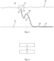
- Fig. 3 shows an offshore structure 15 comprising a floating platform 17 that floats on water 16, and the dynamic submarine power cable 1.
- the floating platform 17 may for example be the floating platform of a floating wind turbine, or a semi-submersible platform for oil and gas applications.
- the dynamic submarine power cable 1 is suspended from the floating platform 17 and extends down to the seabed 19.
- the offshore structure 15 comprises a bend stiffener 21, or alternatively a Bellmouth, connected to the floating platform 17, which is arranged around a top portion of the dynamic submarine power cable 1.
- the bend stiffener 21, or Bellmouth is arranged around a top section 1a of the dynamic submarine power cable 1.
- the first section 8a of the metallic water blocking layer 7 is arranged along the top section 1a of the dynamic submarine power cable 1 as the dynamic submarine power cable 1 hangs from the floating platform 17 and extends to the seabed 19.
- the first section 8a maybe at least 50 m long, such as at least 100 m long, such as at least 150 m long, such as at least 200 m long.
- the first section 8a maybe at most 800 m long, such as at most 600 m long, such as at most 400 m long.
- the dynamic submarine power cable 1 may be provided with buoyance modules 23 to provide a wave configuration to the dynamic submarine power cable 1 as it extends towards the seabed 19.
- the dynamic submarine power cable 1 could alternatively be free hanging from the floating platform 17.
- the dynamic submarine power cable 1 has a bottom section 1b which, like the first section 8a, is arranged hanging in the water column between the floating platform 17 and the seabed 19.
- the second section 8b is arranged along the bottom section 1b of the dynamic submarine power cable 1.
- the second section 8b may according to one example be at least 100 m long, such as at least 200 m long.
- the second section 8b may according to one example be at most 3000 m or at most 5000 m long. Generally, the length of the second section 8b depends on the water depth.
- a portion of the bottom section 1b and thus of the second section 8b extends to the seabed 19 and may extend along the seabed 19 to a joint 27 on the seabed 19, which connects the dynamic submarine power cable 1 to a static submarine power cable 27.
- a dynamic submarine power cable such as the dynamic submarine power cable 1
- the first section 8a and the second section 8b is produced in one length.
- the insulation system 5 may be made in one length along the entire length of the dynamic submarine power cable 1. Thus, in this example, no factory joints which joint the insulation system 5 are made.
- a metal tube is first arranged around the insulation system 5.
- the metal tube may be made by folding a metal sheath around the insulation system 5 and longitudinally welding, soldering, or gluing of the metal sheath.
- the first section 8a and the second section 8b are produced in two separate lengths and then jointed.
- the dynamic submarine power cable 1, or more typically, the one or more power cores of the submarine power cable 1, may typically also be produced in two lengths that are jointed.
- a step a) the metal tube arranged around an insulation system 5 is corrugated to form the corrugated metallic water blocking layer 7a.
- step a) the first section 8a of the metallic water blocking layer 7 is produced.
- Step a) is carried out by a corrugation machine through which at least that part or portion of the dynamic submarine power cable 1 for which the metal tube is corrugated passes.
- a diameter reduction of the metal tube arranged around an insulation system 5 is performed to form the smooth metallic water blocking layer 7b.
- Step b) is carried out by a roller assembly through which the second section 8b of the dynamic submarine power cable 1 passes.
- step b) the second section 8b of the metallic water blocking layer 7 is produced.
- Step a) may be carried out before step b), or step b) may be carried out before step a). If the first section 8a and the second section 8b are physically separate lengths of the metallic water blocking layer 7 during steps a) and b), steps a) and b) may be carried out simultaneously in case the factory provides for such production possibilities.
- the corrugated metallic water blocking layer 7a and the smooth dynamic metallic water blocking layer 7b forms the metallic water blocking layer 7, which in this case may be made in one length in the region where it transitions from being corrugated to being smooth.
- the first section 8a and the second section 8b have to be jointed after steps a) and b) have been carried out.
- the jointing may involve jointing the conductor 3, the insulation system 5, and the corrugated metallic water blocking layer 7a and the smooth metallic water blocking layer 7b.
- the jointing of the corrugated metallic water blocking layer 7a and the smooth metallic water blocking layer 7b may for example be done by soldering or welding.
- only a portion of one of the metal tubes is corrugated.
- the remaining length of this metal tube may be made smooth by subjecting it to diameter reduction, and the smooth portion may be jointed with the smooth metallic water blocking layer 7b made in step b).
Landscapes
- Engineering & Computer Science (AREA)
- Manufacturing & Machinery (AREA)
- Ocean & Marine Engineering (AREA)
- Architecture (AREA)
- Civil Engineering (AREA)
- Structural Engineering (AREA)
- Chemical & Material Sciences (AREA)
- Combustion & Propulsion (AREA)
- Mechanical Engineering (AREA)
- Insulated Conductors (AREA)
- Laying Of Electric Cables Or Lines Outside (AREA)
Abstract
Description
- The present disclosure generally relates to dynamic submarine power cables.
- Dynamic submarine power cables are subjected to movements when suspended from a floating structure to the seabed. Therefore, such cables typically have a corrugated metallic water barrier to provide better fatigue properties to the metallic water barrier. An example of such a solution is disclosed in
EP2896053 . - Dynamic submarine power cables are nowadays considered for use in deepwater installations, e.g., for water depths of more than 1500 m or more than 2000 m. This makes using corrugated metallic water barriers problematic because of the higher hydrostatic pressure at deep sea, which may cause buckling of the corrugated metallic water barrier. Non-controllable changes to the original design of a metallic water barrier, such as by buckling, are undesirable, especially if the power cable is constantly moving, because the deformation may for instance cause stress concentrations reducing the fatigue life of the metallic water barrier.
- In view of the above an object of the present disclosure is to provide a dynamic submarine power cable which solves or at least mitigates the problems of the prior art.
- There is hence according to a first aspect of the present disclosure provided a dynamic submarine power cable comprising: a conductor, an insulation system arranged around the conductor, wherein the insulation system comprises an inner semiconducting layer arranged around the conductor, an insulation layer arranged around the inner semiconducting layer, and an outer semiconducting layer arranged around the insulation layer, and a metallic water blocking layer arranged around the insulation system, wherein the metallic water blocking layer is formed by a first section that is a corrugated metallic water blocking layer and a second section that is a smooth metallic water blocking layer.
- The top section of a dynamic submarine power cable is the most fatigueaffected portion of the dynamic submarine power cable due to the wave motion in the surface region of the body of water in which the dynamic submarine power cable is installed. The corrugated metallic water blocking layer provides better fatigue resistance properties than a smooth metallic water blocking layer and the dynamic submarine power cable is beneficially installed such that the corrugated metallic water blocking layer extends along the top section of the dynamic submarine power cable. Further down in the water column, the dynamic submarine power cable is much less affected by wave motion but at larger depths the hydrostatic pressure could affect the shape of a corrugated metallic water blocking layer. Therefore, beneficially, the smooth metallic water blocking layer forms the bottom section of the dynamic submarine power cable to better withstand the ambient hydrostatic pressure without any deformation of the metallic water blocking layer at larger water depths.
- The smooth metallic water blocking layer is non-corrugated.
- According to one embodiment the first section is a top section, and the second section is a bottom section of the dynamic submarine power cable in an installed state.
- According to one embodiment the corrugated metallic water blocking layer may extend from a first end, or within 10-15 metres from the first end, of the dynamic submarine power cable until it transitions to the smooth metallic water blocking layer, which extends from the transition point to a second end of the dynamic submarine power cable, opposite to the first end.
- According to one embodiment the first section is at least 50 m long, such as at least 100 m long, such as at least 150 m long, such as at least 200 m long.
- According to one embodiment the first section is at most 800 m long, such as at most 600 m long, such as at most 400 m long.
- According to one embodiment the metallic water blocking layer is made in one length in a region where it transitions from being the corrugated metallic water blocking layer to being the smooth metallic water blocking layer.
- According to one embodiment the insulation system is made in one length along the entire length of the dynamic submarine power cable. The dynamic submarine power cable may thus be without any factory joints along its entire length. A factory joint connects two semi-finished cable lengths, before any armour is applied, and involves restoration of the insulation system by means of vulcanisation. Typically, for factory joints, the conductors of the two semi-finished cable lengths are joined by welding.
- One embodiment comprises a polymeric layer arranged around the metallic water blocking layer, wherein the polymeric layer extends along the first section and along the second section.
- The polymeric layer maybe dielectric or semiconductive.
- One embodiment comprises an adhesive, wherein the adhesive is arranged between the polymeric layer and the smooth metallic water blocking layer in the second section to bond the polymeric layer to the metallic water blocking layer along the second section.
- The adhesive may be dielectric if the polymeric layer is dielectric, or semiconductive if the polymeric layer is semiconductive.
- According to one embodiment the metallic water blocking layer comprises one of copper, stainless steel, or aluminium.
- The dynamic submarine power cable may be a medium voltage or a high voltage submarine power cable.
- The dynamic submarine power cable may be an AC or a DC dynamic submarine power cable.
- The dynamic submarine power cable may comprise one or more power cores, each power core comprising a conductor, an insulation system arranged around the conductor, wherein the insulation system comprises an inner semiconducting layer arranged around the conductor, an insulation layer arranged around the inner semiconducting layer, and an outer semiconducting layer arranged around the insulation layer, and a metallic water blocking layer arranged around the insulation system, wherein the metallic water blocking layer is formed by a first section that is a corrugated metallic water blocking layer and a second section that is a smooth metallic water blocking layer.
- The dynamic submarine power cable may for example comprise, one, two, or three power cores.
- There is according to a second aspect of the present disclosure provided an offshore structure comprising a floating platform, and a dynamic submarine power cable of the first aspect suspended from the floating platform, wherein the first section and the second section of the metallic water blocking layer are arranged in a water column between the floating platform and the seabed, wherein the first section forms a top section and the second section forms a bottom section of the dynamic submarine power cable in the water column.
- Both the first section and the second section of the dynamic submarine power cable are thus in a suspended state, hanging from the floating platform, in the water column.
- The dynamic submarine power cable may be jointed with a static submarine power cable laid on the seabed. The joint maybe located on the seabed, and thus a portion of the second section of the dynamic submarine power cable may be laid on the seabed.
- There is according to a third aspect of the present disclosure provided a method of producing a dynamic submarine power cable comprising a conductor, and an insulation system arranged around the conductor, wherein the insulation system comprises an inner semiconducting layer arranged around the conductor, an insulation layer arranged around the inner semiconducting layer, and an outer semiconducting layer arranged around the insulation layer, the method comprising: a) corrugating a metal tube arranged around an insulation system to form a corrugated metallic water blocking layer, which is a first section of a metallic water blocking layer of the dynamic submarine power cable, and b) performing a diameter reduction of a metal tube arranged around an insulation system to form a smooth metallic water blocking layer, which is a second section of the metallic water blocking layer, the first section and the second section together defining the axial length of the metallic water blocking layer.
- According to one embodiment during steps a) and b) the dynamic submarine power cable is in one length, and the metal tube in step a) and the metal tube in step b) are the same, made in one length.
- According to one embodiment the metal tubes in steps a) and b) are physically separate metal tubes, wherein the method comprises, after steps a) and b), c) jointing the first section and the second section.
- Generally, all terms used in the claims are to be interpreted according to their ordinary meaning in the technical field, unless explicitly defined otherwise herein. All references to "a/an/the element, apparatus, component, means", etc. are to be interpreted openly as referring to at least one instance of the element, apparatus, component, means, etc., unless explicitly stated otherwise.
- The specific embodiments of the inventive concept will now be described, by way of example, with reference to the accompanying drawings, in which:
-
Fig. 1 schematically shows an example of a dynamic submarine power cable; -
Fig. 2 schematically shows a side view of a portion of a metallic water blocking layer that transitions between being corrugated and smooth; -
Fig. 3 schematically shows an offshore structure; and -
Fig. 4 is a flowchart of a method of producing a dynamic submarine power cable. - The inventive concept will now be described more fully hereinafter with reference to the accompanying drawings, in which exemplifying embodiments are shown. The inventive concept may, however, be embodied in many different forms and should not be construed as limited to the embodiments set forth herein; rather, these embodiments are provided by way of example so that this disclosure will be thorough and complete, and will fully convey the scope of the inventive concept to those skilled in the art. Like numbers refer to like elements throughout the description.
-
Fig. 1 shows an example of a dynamicsubmarine power cable 1. The dynamicsubmarine power cable 1 depicted inFig. 1 has a single power core but could alternatively comprise more than one power core, such as two or three power cores. - The exemplified dynamic
submarine power cable 1 comprises aconductor 3. Theconductor 3 may typically comprise copper or aluminium. - The dynamic
submarine power cable 1 comprises aninsulation system 5. Theinsulation system 5 comprises an innersemiconducting layer 5a arranged around theconductor 3. - The
insulation system 5 comprises aninsulation layer 5b arranged radially outside the innersemiconducting layer 5a. Further, theinsulation system 5 comprises an outersemiconducting layer 5c arranged radially outside theinsulation layer 5b. - The
insulation system 5 may for example be a triple extruded insulation system comprising polymeric material. Alternatively, theinsulation system 5 may be formed of layers of oil impregnated paper, with the innermost and outermost layers being semiconducting paper layers. - The dynamic
submarine power cable 1 comprises a metallicwater blocking layer 7 extending along a majority of the length, or the entire length, of the dynamicsubmarine power cable 1. The metallicwater blocking layer 7 may for example comprise copper and may in this case be pure copper or a copper alloy, or it may comprise aluminium and may in this case be pure aluminium or an aluminium alloy, or have a laminated structure, or it may comprise stainless steel. - The metallic
water blocking layer 7 is arranged radially outside theinsulation system 5. - The metallic
water blocking layer 7 may be formed of a metal sheath folded around theinsulation system 5, which is longitudinally welded during production of the dynamicsubmarine power cable 1. - The dynamic
submarine power cable 1 may comprise a cushion layer arranged between theinsulation system 5 and the metallicwater blocking layer 7. The cushion layer may comprise a polymeric material. The cushion layer may be semiconductive. - The metallic
water blocking layer 7 includes a first section that is corrugated and a second section that is smooth, i.e., non-corrugated. In particular, along the entire length of a first section the metallicwater blocking layer 7 is a corrugated metallic water blocking layer, and along the entire length of a second section the metallicwater blocking layer 7 is a smooth metallic water blocking layer. The first section transitions to the second section. Thus, the corrugated metallic water blocking layer transitions to the smooth metallic water blocking layer. - The corrugations of the corrugated metallic water blocking layer are formed in an axial direction of the dynamic
submarine power cable 1. Hereto, the metallicwater blocking layer 7 is undulating in the axial direction along the first section. - The dynamic
submarine power cable 1 comprises apolymeric layer 9. Thepolymeric layer 9 is arranged around the metallicwater blocking layer 7. Thepolymeric layer 9 extends along the first section and along the second section. Thepolymeric layer 9 may for example comprise a polyolefin such polyethylene or polypropylene, or polyvinylchloride. - The
polymeric layer 9 may be in direct contact with the corrugated metallic water blocking layer. - The dynamic
submarine power cable 1 may comprise an adhesive provided between thepolymeric layer 9 and the metallicwater blocking layer 7 to bond thepolymeric layer 9 to the metallicwater blocking layer 7 along the second section, i.e., where the metallicwater blocking layer 7 is a smooth metallic water blocking layer. - The adhesive may for example comprise a polyolefin such as polyethylene.
- The dynamic
submarine power cable 1 may comprise one or more armour layers 11. Eacharmour layer 11 comprises a plurality ofarmour wires 11a. Thearmour wires 11a may be helically laid around thepolymeric layer 9. Thearmour wires 11a may be metal armour wires, such as steel, e.g., galvanized steel or stainless steel, or copper wires, or they may be made of synthetic material such as a polymeric material, or some of the armour wires may be made of metal and others may be made of a synthetic material. - The dynamic
submarine power cable 1 may comprise a bedding layer arranged between thepolymeric layer 9 and the innermost layer of the one or more armour layers 11 in case the dynamicsubmarine power cable 1 comprises anarmour layer 11. The bedding layer may be made of a polymeric material. - The dynamic
submarine power cable 1 comprises an outer sheath or outer serving 13, forming an outermost layer of the dynamicsubmarine power cable 1. The outer sheath or outer serving 13 may comprise a polymeric material. -
Fig. 2 shows a side view of a portion of the dynamicsubmarine power cable 1. In particular, the metallicwater blocking layer 7 is shown with components external to the metallicwater blocking layer 7 being removed for clarity. -
Fig. 2 shows that thefirst section 8a, of which only a portion is shown, of the metallicwater blocking layer 7 is the corrugated metallicwater blocking layer 7a and that thesecond section 8b, of which only a portion is shown, is the smooth metallicwater blocking layer 7b. The metallicwater blocking layer 7 extends continuously along the entire length of the dynamicsubmarine power cable 1, and transitions between being corrugated and smooth. -
Fig. 3 shows anoffshore structure 15 comprising a floatingplatform 17 that floats onwater 16, and the dynamicsubmarine power cable 1. - The floating
platform 17 may for example be the floating platform of a floating wind turbine, or a semi-submersible platform for oil and gas applications. - The dynamic
submarine power cable 1 is suspended from the floatingplatform 17 and extends down to theseabed 19. - The
offshore structure 15 comprises abend stiffener 21, or alternatively a Bellmouth, connected to the floatingplatform 17, which is arranged around a top portion of the dynamicsubmarine power cable 1. In particular, thebend stiffener 21, or Bellmouth, is arranged around atop section 1a of the dynamicsubmarine power cable 1. Thefirst section 8a of the metallicwater blocking layer 7 is arranged along thetop section 1a of the dynamicsubmarine power cable 1 as the dynamicsubmarine power cable 1 hangs from the floatingplatform 17 and extends to theseabed 19. - The
first section 8a maybe at least 50 m long, such as at least 100 m long, such as at least 150 m long, such as at least 200 m long. Thefirst section 8a maybe at most 800 m long, such as at most 600 m long, such as at most 400 m long. - The dynamic
submarine power cable 1 may be provided withbuoyance modules 23 to provide a wave configuration to the dynamicsubmarine power cable 1 as it extends towards theseabed 19. The dynamicsubmarine power cable 1 could alternatively be free hanging from the floatingplatform 17. - The dynamic
submarine power cable 1 has abottom section 1b which, like thefirst section 8a, is arranged hanging in the water column between the floatingplatform 17 and theseabed 19. Thesecond section 8b is arranged along thebottom section 1b of the dynamicsubmarine power cable 1. - The
second section 8b may according to one example be at least 100 m long, such as at least 200 m long. Thesecond section 8b may according to one example be at most 3000 m or at most 5000 m long. Generally, the length of thesecond section 8b depends on the water depth. - A portion of the
bottom section 1b and thus of thesecond section 8b extends to theseabed 19 and may extend along theseabed 19 to a joint 27 on theseabed 19, which connects the dynamicsubmarine power cable 1 to a staticsubmarine power cable 27. - Turning now to
Fig. 4 , a method of producing a dynamic submarine power cable such as the dynamicsubmarine power cable 1 will be described. - In a first example, the
first section 8a and thesecond section 8b is produced in one length. Theinsulation system 5 may be made in one length along the entire length of the dynamicsubmarine power cable 1. Thus, in this example, no factory joints which joint theinsulation system 5 are made. - A metal tube is first arranged around the
insulation system 5. The metal tube may be made by folding a metal sheath around theinsulation system 5 and longitudinally welding, soldering, or gluing of the metal sheath. - In a second example, the
first section 8a and thesecond section 8b are produced in two separate lengths and then jointed. In this case, the dynamicsubmarine power cable 1, or more typically, the one or more power cores of thesubmarine power cable 1, may typically also be produced in two lengths that are jointed. - In both examples, in a step a) the metal tube arranged around an
insulation system 5 is corrugated to form the corrugated metallicwater blocking layer 7a. - In step a) the
first section 8a of the metallicwater blocking layer 7 is produced. - Step a) is carried out by a corrugation machine through which at least that part or portion of the dynamic
submarine power cable 1 for which the metal tube is corrugated passes. - In both examples, in a step b) a diameter reduction of the metal tube arranged around an
insulation system 5 is performed to form the smooth metallicwater blocking layer 7b. - Step b) is carried out by a roller assembly through which the
second section 8b of the dynamicsubmarine power cable 1 passes. - In step b) the
second section 8b of the metallicwater blocking layer 7 is produced. - Step a) may be carried out before step b), or step b) may be carried out before step a). If the
first section 8a and thesecond section 8b are physically separate lengths of the metallicwater blocking layer 7 during steps a) and b), steps a) and b) may be carried out simultaneously in case the factory provides for such production possibilities. - In the first example, once steps a) and b) have been carried out, the corrugated metallic
water blocking layer 7a and the smooth dynamic metallicwater blocking layer 7b forms the metallicwater blocking layer 7, which in this case may be made in one length in the region where it transitions from being corrugated to being smooth. - In the second example, the
first section 8a and thesecond section 8b have to be jointed after steps a) and b) have been carried out. The jointing may involve jointing theconductor 3, theinsulation system 5, and the corrugated metallicwater blocking layer 7a and the smooth metallicwater blocking layer 7b. The jointing of the corrugated metallicwater blocking layer 7a and the smooth metallicwater blocking layer 7b may for example be done by soldering or welding. - In one variation of the second example, only a portion of one of the metal tubes is corrugated. The remaining length of this metal tube may be made smooth by subjecting it to diameter reduction, and the smooth portion may be jointed with the smooth metallic
water blocking layer 7b made in step b). - The inventive concept has mainly been described above with reference to a few examples. However, as is readily appreciated by a person skilled in the art, other embodiments than the ones disclosed above are equally possible within the scope of the inventive concept, as defined by the appended claims.
Claims (14)
- A dynamic submarine power cable (1) comprising:a conductor (3),an insulation system (5) arranged around the conductor (3),wherein the insulation system (5) comprises an inner semiconducting layer (5a) arranged around the conductor (3), an insulation layer (5b) arranged around the inner semiconducting layer (5a), and an outer semiconducting layer (5c) arranged around the insulation layer (5a), anda metallic water blocking layer (7) arranged around the insulation system (5),wherein the metallic water blocking layer (7) is formed by a first section (8a) that is a corrugated metallic water blocking layer (7a) and a second section (8b) that is a smooth metallic water blocking layer (7b).
- The dynamic submarine power cable (1) as claimed in claim 1, wherein the first section (1a) is a top section, and the second section (1b) is a bottom section of the dynamic submarine power cable (1) in an installed state.
- The dynamic submarine power cable (1) as claimed in claim 1 or 2, wherein the corrugated metallic water blocking layer (7a) extend from a first end, or within 10-15 metres from the first end, of the dynamic submarine power cable (1) until it transitions to the smooth metallic water blocking layer (7b), which extends from the transition point to a second end of the dynamic submarine power cable (1), opposite to the first end.
- The dynamic submarine power cable (1) as claimed in any of the preceding claims, wherein the first section (8a) is at least 50 m long, such as at least 100 m long, such as at least 150 m long, such as at least 200 m long.
- The dynamic submarine power cable (1) as claimed in any of the preceding claims, wherein the first section (8a) is at most 800 m long, such as at most 600 m long, such as at most 400 m long.
- The dynamic submarine power cable (1) as claimed in any of the preceding claims, wherein the metallic water blocking layer (7) is made in one length in a region where it transitions from being the corrugated metallic water blocking layer (7a) to being the smooth metallic water blocking layer (7b).
- The dynamic submarine power cable (1) as claimed in any of the preceding claims, wherein the insulation system (5) is made in one length along the entire length of the dynamic submarine power cable (1).
- The dynamic submarine power cable (1) as claimed in any of the preceding claims, comprising a polymeric layer (9) arranged around the metallic water blocking layer (7), wherein the polymeric layer (9) extends along the first section (1a) and along the second section (1b).
- The dynamic submarine power cable (1) as claimed in claim 8, comprising an adhesive, wherein the adhesive is arranged between the polymeric layer (9) and the smooth metallic water blocking layer (7b) in the second section (8b) to bond the polymeric layer (9) to the metallic water blocking layer (7) along the second section (1b).
- The dynamic submarine power cable (1) as claimed in any of the preceding claims, wherein the metallic water blocking layer (7) comprises one of copper, stainless steel, or aluminium.
- Offshore structure (15) comprising a floating platform (17), and a dynamic submarine power cable (1) as claimed in any of claims 1-10 suspended from the floating platform (17), wherein the first section (8a) and the second section (8b) of the metallic water blocking layer (7) are arranged in a water column between the floating platform (17) and the seabed (19), wherein the first section (8a) forms a top section, and the second section (8b) forms a bottom section of the dynamic submarine power cable (1) in the water column.
- Method of producing a dynamic submarine power cable (1) comprising a conductor (3), and an insulation system (5) arranged around the conductor (3), wherein the insulation system (5) comprises an inner semiconducting layer (5a) arranged around the conductor (3), an insulation layer (5b) arranged around the inner semiconducting layer (5a), and an outer semiconducting layer (5c) arranged around the insulation layer (5b), the method comprising:a) corrugating a metal tube arranged around an insulation system (5) to form a corrugated metallic water blocking layer (7a), which is a first section (8a) of a metallic water blocking layer (7) of the dynamic submarine power cable (1), andb) performing a diameter reduction of a metal tube arranged around an insulation system (5) to form a smooth metallic water blocking layer (7b), which is a second section (8b) of the metallic water blocking layer (7),the first section (8a) and the second section (8b) together defining the axial length of the metallic water blocking layer (7).
- The method as claimed in claim 12, wherein during steps a) and b) the dynamic submarine power cable (1) is in one length, and the metal tube in step a) and the metal tube in step b) are the same, made in one length.
- The method as claimed in claim 12, wherein the metal tubes in steps a) and b) are physically separate metal tubes, wherein the method comprises, after steps a) and b), c) jointing the first section (8a) and the second section (8b).
Priority Applications (5)
| Application Number | Priority Date | Filing Date | Title |
|---|---|---|---|
| EP22199612.7A EP4350717A1 (en) | 2022-10-04 | 2022-10-04 | Dynamic submarine power cable with corrugated and smooth metallic water barrier |
| US18/473,452 US20240112832A1 (en) | 2022-10-04 | 2023-09-25 | Dynamic Submarine Power Cable With Corrugated And Smooth Metallic Water Barrier |
| KR1020230130967A KR20240047320A (en) | 2022-10-04 | 2023-09-27 | Dynamic submarine power cable with corrugated and smooth metallic water barrier |
| JP2023169040A JP2024054085A (en) | 2022-10-04 | 2023-09-29 | Dynamic submarine power cable with corrugated and smooth metallic water barrier |
| CA3215205A CA3215205A1 (en) | 2022-10-04 | 2023-10-03 | Dynamic submarine power cable with corrugated and smooth metallic water barrier |
Applications Claiming Priority (1)
| Application Number | Priority Date | Filing Date | Title |
|---|---|---|---|
| EP22199612.7A EP4350717A1 (en) | 2022-10-04 | 2022-10-04 | Dynamic submarine power cable with corrugated and smooth metallic water barrier |
Publications (1)
| Publication Number | Publication Date |
|---|---|
| EP4350717A1 true EP4350717A1 (en) | 2024-04-10 |
Family
ID=83594029
Family Applications (1)
| Application Number | Title | Priority Date | Filing Date |
|---|---|---|---|
| EP22199612.7A Pending EP4350717A1 (en) | 2022-10-04 | 2022-10-04 | Dynamic submarine power cable with corrugated and smooth metallic water barrier |
Country Status (5)
| Country | Link |
|---|---|
| US (1) | US20240112832A1 (en) |
| EP (1) | EP4350717A1 (en) |
| JP (1) | JP2024054085A (en) |
| KR (1) | KR20240047320A (en) |
| CA (1) | CA3215205A1 (en) |
Cited By (1)
| Publication number | Priority date | Publication date | Assignee | Title |
|---|---|---|---|---|
| NO20240910A1 (en) * | 2024-09-06 | 2026-03-09 | Nexans | A dynamic high-voltage submarine cable and method for producing a dynamic high-voltage submarine cable |
Families Citing this family (2)
| Publication number | Priority date | Publication date | Assignee | Title |
|---|---|---|---|---|
| NO20240678A1 (en) * | 2024-06-21 | 2025-12-22 | Nexans | Transversal reinforcement of a lead-free water barrier for a subsea cable |
| CN118970799A (en) * | 2024-08-30 | 2024-11-15 | 中天科技海缆股份有限公司 | Underwater dynamic submarine cable system suitable for shallow waters |
Citations (3)
| Publication number | Priority date | Publication date | Assignee | Title |
|---|---|---|---|---|
| US5760334A (en) * | 1996-07-24 | 1998-06-02 | Alcatel Kabel Ag & Co. | Metallic sheath for an electric cable and method of making the same |
| JP2014032912A (en) * | 2012-08-06 | 2014-02-20 | Furukawa Electric Co Ltd:The | Submarine cable excellent in fatigue characteristics and multilayer tape for impervious layer thereof |
| EP2896053A1 (en) | 2012-09-14 | 2015-07-22 | ABB Research Ltd. | A radial water barrier and a dynamic high voltage submarine cable for deep water applications |
Family Cites Families (35)
| Publication number | Priority date | Publication date | Assignee | Title |
|---|---|---|---|---|
| FR2741696B1 (en) * | 1995-11-29 | 1998-01-02 | Coflexip | STRAINER FOR FLEXIBLE PIPING FOR USE IN THE MARINE ENVIRONMENT |
| US7590322B2 (en) * | 2007-03-09 | 2009-09-15 | Superior Essex Communications Lp | Fiber optic cable with enhanced saltwater performance |
| US7936957B1 (en) * | 2007-03-09 | 2011-05-03 | Superior Essex Communications, Lp | High-density fiber optic ribbon cable with enhanced water blocking performance |
| CN102483989B (en) * | 2009-07-03 | 2014-02-19 | 瑞士单浮筒系泊公司 | High voltage electro inductive swivel |
| EP2312591B1 (en) * | 2009-08-31 | 2020-03-04 | Nexans | Fatigue resistant metallic moisture barrier in submarine power cable |
| NO2750144T3 (en) * | 2011-08-23 | 2018-01-06 | ||
| JP5987208B2 (en) * | 2012-08-20 | 2016-09-07 | 矢崎総業株式会社 | Wire harness exterior member and wire harness |
| GB2505660B (en) * | 2012-09-05 | 2014-12-03 | Bpp Cables Ltd | Subsea cables |
| US9424963B1 (en) * | 2012-12-12 | 2016-08-23 | Superior Essex Communications Lp | Moisture mitigation in premise cables |
| CN105431914A (en) * | 2013-06-27 | 2016-03-23 | 普睿司曼股份公司 | Method of manufacturing power cables and related power cable |
| JP5984066B2 (en) * | 2013-08-02 | 2016-09-06 | 住友電装株式会社 | Shield conductive path |
| CA2932466C (en) * | 2013-12-19 | 2017-01-03 | Abb Technology Ltd | An arrangement for a dynamic high voltage subsea cable and a dynamic high voltage subsea cable |
| DE102014206000A1 (en) * | 2014-03-31 | 2015-10-01 | Siemens Aktiengesellschaft | cooler |
| DE102015209432A1 (en) * | 2015-05-22 | 2016-11-24 | Siemens Aktiengesellschaft | Device for DC transmission and cooling method |
| EP3358574A4 (en) * | 2015-09-30 | 2019-08-21 | LS Cable & System Ltd. | SUBMARINE CABLE WITH SHIELDING HETEROGENEOUS |
| GB2552370A (en) * | 2016-07-21 | 2018-01-24 | Jdr Cable Systems Ltd | Insulated cable |
| US10264711B2 (en) * | 2016-11-30 | 2019-04-16 | Data Marine, LLC | Data vessel integrated with cooling and docking station with ancillary service |
| DE102017108389B4 (en) * | 2017-04-20 | 2026-02-12 | Leoni Kabel Gmbh | Barrier layer against migration of a substance, electrical conductor, method for manufacturing a coated cable and use of polyethylene furanoate as a barrier layer |
| DK3438993T3 (en) * | 2017-08-02 | 2021-12-20 | Nexans | DYNAMIC POWER CABLE |
| CA3100991A1 (en) * | 2018-05-25 | 2019-11-28 | Prysmian S.P.A. | High voltage power cable with fatigue-resistant water barrier |
| DE102018125323A1 (en) * | 2018-10-12 | 2020-04-16 | Innogy Se | Wind turbine |
| EP3786982B1 (en) * | 2019-08-26 | 2023-06-07 | Nexans | Cunisi alloy cable sheathing |
| WO2021050324A1 (en) * | 2019-09-13 | 2021-03-18 | Commscope Technologies Llc | Hybrid cable for distributed power connectivity |
| IT201900016406A1 (en) * | 2019-09-16 | 2021-03-16 | Prysmian Spa | PROCESS TO PRODUCE A SUBMARINE POWER CABLE AND A POWER CABLE THUS PRODUCED. |
| EP3839981A1 (en) * | 2019-12-19 | 2021-06-23 | NKT HV Cables AB | Ac submarine power cable with reduced losses |
| JP7384095B2 (en) * | 2020-03-27 | 2023-11-21 | 住友電装株式会社 | wire harness |
| EP4068309A1 (en) * | 2021-03-29 | 2022-10-05 | Nexans | Low resistance pe sheath with combined adhesive and mechanical properties |
| GB202104947D0 (en) * | 2021-04-07 | 2021-05-19 | Advanced Insulation Ltd | Retaining element |
| US12030597B2 (en) * | 2021-07-22 | 2024-07-09 | Chevron U.S.A. Inc. | High voltage submarine cable systems |
| DE102021131422A1 (en) * | 2021-11-30 | 2023-06-01 | Rwe Renewables Gmbh | Submarine cable system and method of laying a submarine cable system |
| NO347780B1 (en) * | 2021-12-03 | 2024-03-25 | Kongsberg Maritime As | Pull-in of dynamic cables for floating wind turbines |
| EP4243038B1 (en) * | 2022-03-10 | 2026-02-18 | Nexans | Water barrier materials for a dynamic power cable for submarine applications |
| IT202200006962A1 (en) * | 2022-04-07 | 2023-10-07 | Prysmian Spa | POWER OR DATA TRANSMISSION CABLE WITH METAL WATER BARRIER AND MANUFACTURING PROCESS OF SUCH CABLE. |
| US12676250B2 (en) * | 2022-07-18 | 2026-07-07 | RSCC Wire and Cable LLC | Cable substitute for mineral-insulated cables in nuclear facilities |
| EP4345851A1 (en) * | 2022-09-30 | 2024-04-03 | NKT HV Cables AB | Submarine power cable with slip additive |
-
2022
- 2022-10-04 EP EP22199612.7A patent/EP4350717A1/en active Pending
-
2023
- 2023-09-25 US US18/473,452 patent/US20240112832A1/en active Pending
- 2023-09-27 KR KR1020230130967A patent/KR20240047320A/en active Pending
- 2023-09-29 JP JP2023169040A patent/JP2024054085A/en active Pending
- 2023-10-03 CA CA3215205A patent/CA3215205A1/en active Pending
Patent Citations (4)
| Publication number | Priority date | Publication date | Assignee | Title |
|---|---|---|---|---|
| US5760334A (en) * | 1996-07-24 | 1998-06-02 | Alcatel Kabel Ag & Co. | Metallic sheath for an electric cable and method of making the same |
| JP2014032912A (en) * | 2012-08-06 | 2014-02-20 | Furukawa Electric Co Ltd:The | Submarine cable excellent in fatigue characteristics and multilayer tape for impervious layer thereof |
| EP2896053A1 (en) | 2012-09-14 | 2015-07-22 | ABB Research Ltd. | A radial water barrier and a dynamic high voltage submarine cable for deep water applications |
| US20150248951A1 (en) * | 2012-09-14 | 2015-09-03 | Abb Research Ltd | Radial water barrier and a dynamic high voltage submarine cable for deep water applications |
Non-Patent Citations (2)
| Title |
|---|
| RESNER LESZEK ET AL: "Radial Water Barrier in Submarine Cables, Current Solutions and Innovative Development Directions", ENERGIES, vol. 14, no. 10, 12 May 2021 (2021-05-12), pages 2761, XP055958440, DOI: 10.3390/en14102761 * |
| WEERHEIM RUBEN: "Development of dynamic power cables for commercial floating wind farms", REPORT LITERATURE ASSIGNMENT, 12 November 2018 (2018-11-12), XP055794185, Retrieved from the Internet <URL:https://repository.tudelft.nl/islandora/object/uuid%3A487ba1e5-2764-4e96-808c-a9ee2772219d> [retrieved on 20210412] * |
Cited By (2)
| Publication number | Priority date | Publication date | Assignee | Title |
|---|---|---|---|---|
| NO20240910A1 (en) * | 2024-09-06 | 2026-03-09 | Nexans | A dynamic high-voltage submarine cable and method for producing a dynamic high-voltage submarine cable |
| EP4752912A1 (en) | 2024-09-06 | 2026-06-03 | Nexans | A dynamic high-voltage submarine cable and method for producing a dynamic high-voltage submarine cable |
Also Published As
| Publication number | Publication date |
|---|---|
| US20240112832A1 (en) | 2024-04-04 |
| JP2024054085A (en) | 2024-04-16 |
| CA3215205A1 (en) | 2024-04-04 |
| KR20240047320A (en) | 2024-04-12 |
Similar Documents
| Publication | Publication Date | Title |
|---|---|---|
| US20240112832A1 (en) | Dynamic Submarine Power Cable With Corrugated And Smooth Metallic Water Barrier | |
| EP3098820B1 (en) | Undersea cable, undersea cable installation structure, and method for installing undersea cable | |
| US10056171B2 (en) | Submarine cable and multilayer tape for impermeable layer of same | |
| KR101457330B1 (en) | Undersea cable, multilayer tape for water shielding layer of undersea cable, and method for improving fatigue characteristics of undersea cable | |
| US9029704B2 (en) | Electric power cable | |
| GB2511152A (en) | Electric submersible pump cables for harsh environments | |
| US12431696B2 (en) | Rigid submarine power cable joint | |
| AU2013407859B2 (en) | An arrangement for a dynamic high voltage subsea cable and a dynamic high voltage subsea cable | |
| US20240355506A1 (en) | Dynamic Submarine Power Cable System with Bend Restriction Device | |
| Leroy et al. | Assessing mechanical stresses in dynamic power cables for floating offshore wind farms | |
| JP5323973B1 (en) | Underwater cable with excellent fatigue characteristics and multilayer tape for water shielding layer | |
| WO2025073889A1 (en) | Offshore power generating system | |
| WO2025073893A1 (en) | Subsea transmission power cable | |
| US11450455B2 (en) | Electrical cable for vertical applications | |
| KR20260035783A (en) | A dynamic high-voltage submarine cable and method for producing a dynamic high-voltage submarine cable | |
| EP4517784A1 (en) | Method of manufacturing a dynamic submarine power cable with high friction layer | |
| WO2025073891A1 (en) | Subsea transmission power cable | |
| JP2025137446A (en) | Submarine DC power cable |
Legal Events
| Date | Code | Title | Description |
|---|---|---|---|
| PUAI | Public reference made under article 153(3) epc to a published international application that has entered the european phase |
Free format text: ORIGINAL CODE: 0009012 |
|
| STAA | Information on the status of an ep patent application or granted ep patent |
Free format text: STATUS: THE APPLICATION HAS BEEN PUBLISHED |
|
| AK | Designated contracting states |
Kind code of ref document: A1 Designated state(s): AL AT BE BG CH CY CZ DE DK EE ES FI FR GB GR HR HU IE IS IT LI LT LU LV MC ME MK MT NL NO PL PT RO RS SE SI SK SM TR |
|
| STAA | Information on the status of an ep patent application or granted ep patent |
Free format text: STATUS: REQUEST FOR EXAMINATION WAS MADE |
|
| 17P | Request for examination filed |
Effective date: 20241010 |
|
| RBV | Designated contracting states (corrected) |
Designated state(s): AL AT BE BG CH CY CZ DE DK EE ES FI FR GB GR HR HU IE IS IT LI LT LU LV MC ME MK MT NL NO PL PT RO RS SE SI SK SM TR |
|
| STAA | Information on the status of an ep patent application or granted ep patent |
Free format text: STATUS: EXAMINATION IS IN PROGRESS |
|
| 17Q | First examination report despatched |
Effective date: 20260414 |