EP4350663A1 - Vehicle motion control device and vehicle motion control method - Google Patents
Vehicle motion control device and vehicle motion control method Download PDFInfo
- Publication number
- EP4350663A1 EP4350663A1 EP22811108.4A EP22811108A EP4350663A1 EP 4350663 A1 EP4350663 A1 EP 4350663A1 EP 22811108 A EP22811108 A EP 22811108A EP 4350663 A1 EP4350663 A1 EP 4350663A1
- Authority
- EP
- European Patent Office
- Prior art keywords
- vehicle
- speed
- command value
- information
- route
- Prior art date
- Legal status (The legal status is an assumption and is not a legal conclusion. Google has not performed a legal analysis and makes no representation as to the accuracy of the status listed.)
- Granted
Links
Images

Classifications
-
- B—PERFORMING OPERATIONS; TRANSPORTING
- B60—VEHICLES IN GENERAL
- B60W—CONJOINT CONTROL OF VEHICLE SUB-UNITS OF DIFFERENT TYPE OR DIFFERENT FUNCTION; CONTROL SYSTEMS SPECIALLY ADAPTED FOR HYBRID VEHICLES; ROAD VEHICLE DRIVE CONTROL SYSTEMS FOR PURPOSES NOT RELATED TO THE CONTROL OF A PARTICULAR SUB-UNIT
- B60W30/00—Purposes of road vehicle drive control systems not related to the control of a particular sub-unit, e.g. of systems using conjoint control of vehicle sub-units
- B60W30/14—Adaptive cruise control
- B60W30/143—Speed control
-
- B—PERFORMING OPERATIONS; TRANSPORTING
- B60—VEHICLES IN GENERAL
- B60W—CONJOINT CONTROL OF VEHICLE SUB-UNITS OF DIFFERENT TYPE OR DIFFERENT FUNCTION; CONTROL SYSTEMS SPECIALLY ADAPTED FOR HYBRID VEHICLES; ROAD VEHICLE DRIVE CONTROL SYSTEMS FOR PURPOSES NOT RELATED TO THE CONTROL OF A PARTICULAR SUB-UNIT
- B60W60/00—Drive control systems specially adapted for autonomous road vehicles
- B60W60/001—Planning or execution of driving tasks
-
- B—PERFORMING OPERATIONS; TRANSPORTING
- B60—VEHICLES IN GENERAL
- B60W—CONJOINT CONTROL OF VEHICLE SUB-UNITS OF DIFFERENT TYPE OR DIFFERENT FUNCTION; CONTROL SYSTEMS SPECIALLY ADAPTED FOR HYBRID VEHICLES; ROAD VEHICLE DRIVE CONTROL SYSTEMS FOR PURPOSES NOT RELATED TO THE CONTROL OF A PARTICULAR SUB-UNIT
- B60W50/00—Details of control systems for road vehicle drive control not related to the control of a particular sub-unit, e.g. process diagnostic or vehicle driver interfaces
- B60W50/0097—Predicting future conditions
-
- G—PHYSICS
- G01—MEASURING; TESTING
- G01C—MEASURING DISTANCES, LEVELS OR BEARINGS; SURVEYING; NAVIGATION; GYROSCOPIC INSTRUMENTS; PHOTOGRAMMETRY OR VIDEOGRAMMETRY
- G01C21/00—Navigation; Navigational instruments not provided for in groups G01C1/00 - G01C19/00
- G01C21/26—Navigation; Navigational instruments not provided for in groups G01C1/00 - G01C19/00 specially adapted for navigation in a road network
- G01C21/34—Route searching; Route guidance
-
- B—PERFORMING OPERATIONS; TRANSPORTING
- B60—VEHICLES IN GENERAL
- B60W—CONJOINT CONTROL OF VEHICLE SUB-UNITS OF DIFFERENT TYPE OR DIFFERENT FUNCTION; CONTROL SYSTEMS SPECIALLY ADAPTED FOR HYBRID VEHICLES; ROAD VEHICLE DRIVE CONTROL SYSTEMS FOR PURPOSES NOT RELATED TO THE CONTROL OF A PARTICULAR SUB-UNIT
- B60W2552/00—Input parameters relating to infrastructure
- B60W2552/20—Road profile, i.e. the change in elevation or curvature of a plurality of continuous road segments
-
- B—PERFORMING OPERATIONS; TRANSPORTING
- B60—VEHICLES IN GENERAL
- B60W—CONJOINT CONTROL OF VEHICLE SUB-UNITS OF DIFFERENT TYPE OR DIFFERENT FUNCTION; CONTROL SYSTEMS SPECIALLY ADAPTED FOR HYBRID VEHICLES; ROAD VEHICLE DRIVE CONTROL SYSTEMS FOR PURPOSES NOT RELATED TO THE CONTROL OF A PARTICULAR SUB-UNIT
- B60W2552/00—Input parameters relating to infrastructure
- B60W2552/30—Road curve radius
-
- B—PERFORMING OPERATIONS; TRANSPORTING
- B60—VEHICLES IN GENERAL
- B60W—CONJOINT CONTROL OF VEHICLE SUB-UNITS OF DIFFERENT TYPE OR DIFFERENT FUNCTION; CONTROL SYSTEMS SPECIALLY ADAPTED FOR HYBRID VEHICLES; ROAD VEHICLE DRIVE CONTROL SYSTEMS FOR PURPOSES NOT RELATED TO THE CONTROL OF A PARTICULAR SUB-UNIT
- B60W2554/00—Input parameters relating to objects
-
- B—PERFORMING OPERATIONS; TRANSPORTING
- B60—VEHICLES IN GENERAL
- B60W—CONJOINT CONTROL OF VEHICLE SUB-UNITS OF DIFFERENT TYPE OR DIFFERENT FUNCTION; CONTROL SYSTEMS SPECIALLY ADAPTED FOR HYBRID VEHICLES; ROAD VEHICLE DRIVE CONTROL SYSTEMS FOR PURPOSES NOT RELATED TO THE CONTROL OF A PARTICULAR SUB-UNIT
- B60W2556/00—Input parameters relating to data
- B60W2556/40—High definition maps
-
- B—PERFORMING OPERATIONS; TRANSPORTING
- B60—VEHICLES IN GENERAL
- B60W—CONJOINT CONTROL OF VEHICLE SUB-UNITS OF DIFFERENT TYPE OR DIFFERENT FUNCTION; CONTROL SYSTEMS SPECIALLY ADAPTED FOR HYBRID VEHICLES; ROAD VEHICLE DRIVE CONTROL SYSTEMS FOR PURPOSES NOT RELATED TO THE CONTROL OF A PARTICULAR SUB-UNIT
- B60W2556/00—Input parameters relating to data
- B60W2556/45—External transmission of data to or from the vehicle
- B60W2556/50—External transmission of data to or from the vehicle of positioning data, e.g. GPS [Global Positioning System] data
-
- B—PERFORMING OPERATIONS; TRANSPORTING
- B60—VEHICLES IN GENERAL
- B60W—CONJOINT CONTROL OF VEHICLE SUB-UNITS OF DIFFERENT TYPE OR DIFFERENT FUNCTION; CONTROL SYSTEMS SPECIALLY ADAPTED FOR HYBRID VEHICLES; ROAD VEHICLE DRIVE CONTROL SYSTEMS FOR PURPOSES NOT RELATED TO THE CONTROL OF A PARTICULAR SUB-UNIT
- B60W2720/00—Output or target parameters relating to overall vehicle dynamics
- B60W2720/10—Longitudinal speed
-
- B—PERFORMING OPERATIONS; TRANSPORTING
- B60—VEHICLES IN GENERAL
- B60W—CONJOINT CONTROL OF VEHICLE SUB-UNITS OF DIFFERENT TYPE OR DIFFERENT FUNCTION; CONTROL SYSTEMS SPECIALLY ADAPTED FOR HYBRID VEHICLES; ROAD VEHICLE DRIVE CONTROL SYSTEMS FOR PURPOSES NOT RELATED TO THE CONTROL OF A PARTICULAR SUB-UNIT
- B60W2720/00—Output or target parameters relating to overall vehicle dynamics
- B60W2720/10—Longitudinal speed
- B60W2720/103—Speed profile
Definitions
- the present invention relates to a vehicle motion control device and a vehicle motion control method for controlling motion of a vehicle.
- a type of vehicle motion control techniques such as autonomous driving or driving support, is known to generate a travel path including information such as a travel route and travel speed, each as a travel target of the vehicle, and to control a powertrain, a brake, a steering, and others, so that the vehicle travels along the travel path.
- a simplest technique to control the vehicle to travel along the travel route is, for example, to set a center of a lane as the travel route.
- PTL 1 discloses a more advanced technique to control a vehicle to travel along a travel route.
- a vehicle control device comprising: ... a speed distribution setting part configured to set a speed limit distribution defining a permissible upper limit relative speed, around the surrounding vehicle detected by the surrounding vehicle detection part; and a control part configured to control a speed and/or steering of the own vehicle to satisfy the speed limit distribution set by the speed distribution setting part, wherein the speed distribution setting part is configured to set the speed limit distribution such that the speed limit distribution is different for when the information regarding the traveling state of the surrounding vehicle has been able to be acquired via the vehicle information receiving part, and when no information regarding the traveling state of the surrounding vehicle has been able to be acquired via the vehicle information receiving part", and in claim 2, "the vehicle control device ... wherein the speed distribution setting part is configured to lower a speed limit in the speed limit distribution, when no information regarding the traveling state of the surrounding vehicle has been able to be acquired".
- the vehicle control device disclosed in PTL 1 is configured to control vehicle motion by setting a speed limit for relative speed between the own vehicle and the surrounding vehicle traveling around the own vehicle, and sets a different speed limit in accordance with whether or not the traveling state of the surrounding vehicle is acquired.
- the vehicle control device decreases the speed limit such that the own vehicle is less likely to undergo sudden deceleration or steering due to a behavior of the surrounding vehicle and the driver is thus less likely to feel insecure.
- the vehicle control device disclosed in PTL 1 is not configured to set speed of the own vehicle in consideration of curves far ahead that a sensor in the own vehicle does not detect, and thus, is not likely to increase ride comfort of occupants.
- the speed of the own vehicle is set only based on surrounding (nearby) information of the own vehicle detected by the sensor. Then, when the own vehicle has moved forward a predetermined distance, the sensor may detect the curve ahead of the own vehicle. In this case, the speed of the own vehicle needs to fall far below the set speed, thereby resulting in an unstable behavior of the vehicle.
- an object of the present invention is to provide a vehicle motion control device and a vehicle motion control method, each configured to set the speed of the own vehicle in consideration of the nearby information of the own vehicle together with long-distance information of the own vehicle, so as to reduce the unstable behavior of the vehicle.
- the present invention provides a vehicle motion control device including: a nearby information acquisition unit configured to acquire nearby information of a vehicle; a long-distance information acquisition unit configured to acquire long-distance information of the vehicle; and a speed planning unit configured to generate a speed command value as a travel target of the vehicle, based on the nearby information and the long-distance information.
- the present invention provides a vehicle motion control device or a vehicle motion control method configured to generate a speed command value in consideration of nearby information and long-distance information of an own vehicle, so as to reduce an unstable behavior of the vehicle such as emergency braking.
- a vehicle motion control device according to an embodiment of the present invention will be described below with reference to the drawings. Note that, substantially the same or similar configurations are denoted by the same reference signs, and in a case where descriptions overlap, the description thereof may be omitted. Additionally, descriptions of known techniques may be omitted.
- a vehicle motion control device 2 according to a first embodiment of the present invention will be described with reference to FIGS. 1 to 6D .
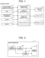
- FIG. 1 is a functional block diagram of an in-vehicle system 1 including a vehicle motion control device 2 of this embodiment.
- the in-vehicle system 1 is installed in an own vehicle and executes vehicle motion control such as driving support or autonomous driving.
- the in-vehicle system 1 includes a vehicle-external communication device 11, a global navigation satellite system (GNSS) 12, a map information storage unit 13, a sensor 14, a human machine interface (HMI) unit 15, a vehicle motion control device 2, a power train system 6, a brake system 7, and a steering system 8. These will be described sequentially below.
- GNSS global navigation satellite system
- HMI human machine interface
- the vehicle-external communication device 11 executes inter-vehicle communication between the own vehicle and other vehicles or road-to-vehicle communication between the own vehicle and a roadside device through wireless communication, and transmit/receives information of the vehicles and a surrounding environment.
- the GNSS 12 receives a radio wave transmitted from an artificial satellite such as a quasi-zenith satellite or a global positioning system (GPS) satellite, and acquires information such as a position of the own vehicle.
- an artificial satellite such as a quasi-zenith satellite or a global positioning system (GPS) satellite
- GPS global positioning system
- the map information storage unit 13 stores general road information used in a navigation system or the like, road information including information related to a width of the road or a curve, e.g., curvature, of the road, information of a road surface condition or a traffic condition, and the information of the vehicles and the surrounding environment as information of travel states of the other vehicles. Based on information acquired through the inter-vehicle communication or the road-to-vehicle communication executed by the vehicle-external communication device 11, the information of the vehicles and the surrounding environment is sequentially updated.
- the sensor 14 corresponds to an external recognition sensor such as an image sensor, a millimeter-wave radar, or a rider for detecting the information of the vehicles and the surrounding environment, or a sensor for detecting information such as an operation by a driver, speed, acceleration, jerk, or angular velocity of the vehicle, or a steering angle of a wheel of the vehicle.
- the information of the vehicle and the surrounding environment detected by the external recognition sensor is, for example, information of various objects surrounding the own vehicle, such as an obstacle, a sign, a lane boundary, a lane edge line, a building, a pedestrian, or the other vehicles.
- the sensor 14 recognizes the lane boundary or the lane edge line based on, for example, a difference in luminance between a white line and a road surface in image data captured by the image sensor.
- the HMI unit 15 displays, on a display, information required by a user based on information received by an input operation of the user, such as selection of a travel mode or setting of a destination, information acquired by the vehicle-external communication device 11, the GNSS 12, and the sensor 14, or information stored in the map information storage unit 13, and provides voice guidance from a speaker. Additionally, the HMI unit 15 generates an alarm for calling the user's attention.
- the travel mode includes, for example, a comfort mode, an economy mode, a sport mode, and others, and the travel mode is optionally or previously set by the user, or is set by an operation management unit 3 based on travel state information as will be described later; and the speed, the acceleration, the jerk, and others of the vehicle are to be set. In other words, an upper limit value of a behavior of the vehicle changes in correspondence to the travel mode. Further, the travel mode includes a shortest time mode for minimizing the travel time, and a shortest distance mode for minimizing the travel distance.
- the vehicle motion control device 2 includes an operation management unit 3, a travel path generation unit 4, and a travel control unit 5.
- the vehicle motion control device 2 is an electronic control unit (ECU) that includes hardware such as an arithmetic device (e.g., a central processing unit (CPU)), a main storage device and an auxiliary storage device such as semiconductor memories, and a communication device, to perform centralized control on the vehicle.
- the arithmetic device executes programs loaded into the main storage device to cause various functions of the operation management unit 3 and others to be implemented.
- the operation management unit 3, the travel path generation unit 4, and the travel control unit 5 have separate configurations, but do not necessarily have the separate configurations. When these units are included in an actual vehicle, various functions of these units may be implemented by a higher-level controller.
- the operation management unit 3 Based on the information acquired by the vehicle-external communication device 11, the GNSS 12, and the sensor 14 together with the map information stored in the map information storage unit 13, the operation management unit 3 generates the information of the position of the own vehicle, the information of various objects surrounding the own vehicle (i.e., the information of the vehicles and the surrounding environment), and information related to the behavior of the vehicle such as lateral acceleration, a yaw rate, or a lateral jerk.
- the operation management unit 3 periodically transmits the information of the position of the own vehicle, the information of the various objects, and the information related to the behavior of the vehicle, through the vehicle-external communication device 11, to the other vehicles and the roadside devices, and concurrently transmits to the map information storage unit 13, so that the map information stored in the map information storage unit 13 is sequentially updated. Further, based on the information of the position of the own vehicle, the information of the various objects, the information related to the behavior of the vehicle, and the information (e.g., the travel mode or the destination) received by the HMI unit 15, the operation management unit 3 sets information of a route from a current position of the vehicle to the destination.
- the information generated or set by the operation management unit 3 may be referred to as the "travel state information".
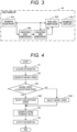
- the travel path generation unit 4 includes an information acquisition unit 41, a route planning unit 42, a speed planning unit 43, and an information output unit 44. Based on the travel state information transmitted from the operation management unit 3 and acquired by the information acquisition unit 41, the travel path generation unit 4 causes the route planning unit 42 to generate a route (hereinafter, referred to as a "route command value P") as a travel target when the vehicle travels along the road.
- the route command value P is generated based on, for example, any one of nearby information of the own vehicle acquired by the sensor 14 or information combining the nearby information and long-distance map information stored in the map information storage unit 13, but the method for generating the route command value P is not limited.
- the speed planning unit 43 generates speed (hereinafter, referred to as a "speed command value") as the travel target when the vehicle travels along the road based on the route command value P and information related to the travel route. Then, the information output unit 44 outputs a travel path including information such as the route command value P and the speed command value.
- speed command value hereinafter, referred to as a "speed command value"
- the travel control unit 5 sets target driving force, target braking force, a target steering angle, and others so that the vehicle travels along the travel path outputted from the travel path generation unit 4, and controls the power train system 6, the brake system 7, and the steering system 8.
- the power train system 6 controls driving force generated by an internal combustion engine, an electric motor, or others based on the operation by the driver or the target driving force outputted from the travel control unit 5.
- the brake system 7 controls braking force generated by a brake caliper or others.
- the steering system 8 controls the steering angle of the wheel.
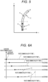
- FIG. 3 is a functional block diagram of the speed planning unit 43.
- the speed planning unit 43 generates the speed command value of the vehicle based on the position or the speed of the vehicle, the upper limit value of the behavior, the route command value P, or others.
- the speed planning unit 43 includes an information acquisition unit 43a, a long-distance route generation unit 43b, a long-distance speed generation unit 43c, a travel speed generation unit 43d, and an information output unit 43e. These will be described sequentially below.
- the information acquisition unit 43a acquires the travel state information from the operation management unit 3, and acquires the route command value P from the route planning unit 42. Then, the information acquisition unit 43a outputs the travel state information and the route command value P to each unit in the speed planning unit 43.
- the long-distance route generation unit 43b Based on the surrounding map included in the travel state information acquired from the information acquisition unit 43a, the long-distance route generation unit 43b generates a route (hereinafter, referred to as a "long-distance route F") to a long-distance area (e.g., 200 m ahead of the own vehicle) beyond an area detectable by the sensor 14.
- a route hereinafter, referred to as a "long-distance route F”
- the route planning unit 42 generates the route command value P
- the calculation load is greater, thereby hindering the route planning unit 42 from generating the route command value P in correspondence to the long-distance travel.
- the long-distance route generation unit 43b generates the long-distance route F requiring less calculation load to compensate for long-distance route information that is not covered by the route command value P.
- the long-distance route F generated by the long-distance route generation unit 43b may have the same start point as the route command value P or may have a start point corresponding to an end point of the route command value P. Accordingly, the long-distance route F is not restrictive.
- the long-distance speed generation unit 43c Based on the travel state information from the information acquisition unit 43a and the long-distance route F from the long-distance route generation unit 43b, the long-distance speed generation unit 43c generates speed (hereinafter, referred to as "long-distance speed") at which a physical quantity falls within a specified value, the physical quantity being related to the behavior of the vehicle when the own vehicle travels along the long-distance route F.
- the specified value may be a predetermined value in consideration of ride comfort or the like or may be a limit value of the vehicle based on a road surface friction coefficient acquired by the sensor 14; and thus, the specified value is not restrictive.
- the speed, at which the physical quantity related to the behavior of the vehicle falls within the specified value may be a speed on assumption of steady circular turning resulted from a square root of a value obtained by dividing a specified value of the lateral acceleration by curvature of the travel route, a speed obtained by integrating a specified value of longitudinal acceleration, or a legal maximum speed or an optional speed limit in a general road. Accordingly, the speed, at which the physical quantity related to the behavior of the vehicle falls within the specified value, is not obtained by any restrictive method.
- the travel speed generation unit 43d Based on the travel state information and the route command value P from the information acquisition unit 43a, together with the long-distance speed from the long-distance speed generation unit 43c, the travel speed generation unit 43d generates the speed command value when the own vehicle travels along the route command value P.
- the travel speed generation unit 43d may generate the speed command value only based on the route command value P. Accordingly, values inputted by the travel speed generation unit 43d to generate the speed command value are not restrictive.
- the travel speed generation unit 43d may give the long-distance route F a less priority or may not use the long-distance route F to generate the speed command value. Accordingly, the values inputted by the travel speed generation unit 43d to generate the speed command value are not restrictive.
- the information output unit 43e outputs, to the information output unit 44, the speed command value from the travel speed generation unit 43d.
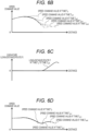
- step S1 the travel speed generation unit 43d acquires the travel state information and the route command value P from the information acquisition unit 43a, and acquires the long-distance speed from the long-distance speed generation unit 43c.
- step S2 based on the travel state information and the route command value P acquired in the step S1, the travel speed generation unit 43d generates the speed (hereinafter, referred to as "nearby speed") at which a physical quantity falls within a specified value, the physical quantity being related to the behavior of the vehicle when the vehicle travels only along the route command value P.
- step S31 based on the long-distance speed acquired in the step S1 and the nearby speed generated in the step S2, the travel speed generation unit 43d determines whether or not the nearby speed is greater than the long-distance speed in an overlapping range of the route command value P and the long-distance route F.
- the process proceeds to step S32; and when the nearby speed is equal to or smaller than the long-distance speed (NO in the step S31), the process proceeds to step S33.
- the nearby speed and the long-distance speed may be compared in a range corresponding to the entire overlapping range of the route command value P and the long-distance route F, or may be compared only at the end point of the route command value P. Accordingly, the range, in which the nearby speed and the long-distance speed are compared, is not restrictive.
- the travel speed generation unit 43d selects the long-distance speed that is at a relatively smaller speed, while in the step S33, the travel speed generation unit 43d selects the nearby speed that is at the relatively smaller speed.
- step S4 based on the long-distance speed or the nearby speed selected, the travel speed generation unit 43d generates the speed command value at which a physical quantity falls within a specified value, the being physical quantity related to the behavior of the vehicle when the own vehicle travels along the route command value P as well as along the long-distance route F beyond the route command value P.
- step S5 the speed command value generated in the step S4 is outputted to the information output unit 43e.
- FIG. 5 is a plan view of the travel route A along which the own vehicle V travels, and shows an example of the route command value P and the long-distance route F, each set within a travelable region R of the own vehicle V at time T n .
- the travelable region R includes an inflection point I as a start point of right turn, a straight line path S as a section up until the inflection point I, and a curve C as a section beyond the inflection point I.
- the sensor 14 of the own vehicle V detects only the straight line path S in the travelable region R and thus, the route command value P generated by the route planning unit 42 of the own vehicle V is linear as shown by an arrow in FIG. 5 .
- the sensor 14 detects the curve C, causing the route command value P to be formed into a curved shape.
- FIG. 6A is a graph of curvature of the route command value P when the own vehicle V of FIG. 5 travels under conventional control
- FIG. 6B is a graph showing an example of the speed command value generated based on the route command value P of FIG. 6A
- FIG. 6C is a graph of curvature of the long-distance route F when the own vehicle V of FIG. 5 travels under the control according to this embodiment
- FIG. 6D is a graph of the speed command value when the own vehicle V of FIG. 5 travels under the control according to this embodiment.
- Each of FIGS. 6A to 6D shows the example of the route command value or others generated during a period from the time T n to time T n+4 . In each of FIGS.
- a broken line represents a value of the time T n
- a dotted line represents a value of the time T n+1
- a one-dot chain line represents a value of time T n+2
- a long broken line represents a value of time T n+3
- a long two-dot chain line represents a value of time T n+4 .
- the curvature of the route command value P at the time T n is zero (straight line).
- the speed command value is generated mainly based on a specified value related to a longitudinal motion of the own vehicle V such as the longitudinal acceleration.
- the speed command value increases as shown with the speed command value at the time T n (broken line) in FIG. 6B .
- the route command value P As the curvature of the curve C is generated. Then, in correspondence to the curvature of the route command value P, and based on a specified value related to lateral motion of the own vehicle V such as the lateral acceleration, the speed command value (see FIG. 6B ) rapidly decreases.
- the speed command value significantly changes between before and after the sensor 14 detects the curve C, and the rapid decrease in the speed command value cannot fall within the specified value related to the decrease in longitudinal acceleration. This may lead to a rapid change in speed, resulting in degraded ride comfort of occupants.
- the speed command value is generated, from the time T n onward, in consideration of the curvature of the route command value P (as shown in FIG. 6A ), in addition to the curvature of the long-distance route F including the curve C (as shown in FIG. 6C ).
- the speed command value generated at one point of time constantly and substantially matches the speed command value generated at a next point following the one point of time. This not only causes the change in speed to be smoother than in the conventional control, but also causes the physical quantity related to the behavior of the vehicle to fall within the specified value where the ride comfort of the occupants is maintained.
- the change in speed is smoother, and the physical quantity related to the behavior of the vehicle falls within the specified value.
- the behavior of the own vehicle is less prone to be unstable (e.g., emergency braking) than in the conventional method, thereby resulting in increased ride comfort of the occupants.
- a vehicle motion control device 2 according to a second embodiment of the present invention will be described with reference to FIG. 7 .
- a detailed description of the same configurations as in the first embodiment will be omitted.
- FIG. 7 is a functional block diagram of a speed planning unit 43 according to the second embodiment. Unlike the speed planning unit 43 of the first embodiment in FIG. 3 , the speed planning unit 43 of this embodiment in FIG. 7 includes a travel speed candidate generation unit 43f instead of the travel speed generation unit 43d, and additionally includes a travel speed selection unit 43g.
- the travel speed candidate generation unit 43f Based on the travel state information and the route command value P from the information acquisition unit 43a, together with the long-distance speed from the long-distance speed generation unit 43c, the travel speed candidate generation unit 43f generates a plurality of speed command value candidates at which a physical quantity falls within a specified value, the physical quantity being related to the behavior of the vehicle when the vehicle travels along one or both of the route command value P and the long-distance route F. Then, the travel speed candidate generation unit 43f outputs the plurality of speed command value candidates to the travel speed selection unit 43g.
- the travel speed selection unit 43g selects one of the plurality of speed command value candidates as a speed command value, and the information output unit 43e outputs the speed command value to the travel control unit 5.
- the travel speed selection unit 43g selects, from the plurality of speed command value candidates generated by the travel speed candidate generation unit 43f, one having a shortest period of travel time; and when the travel state information indicates the economy mode, the travel speed selection unit 43g selects, from the plurality of speed command value candidates, one exhibiting a smallest consumption energy. In other words, the travel speed selection unit 43g selects, from the plurality of speed command value candidates, the speed command value having the shortest period of travel time or the speed command value exhibiting the smallest consumption energy.
- the vehicle motion control device provides, in addition to the same (or similar) effects as (or to) in the first embodiment, control vehicle operation in correspondence to the travel mode selected.
- a configuration of an embodiment may be partially replaced with a configuration of other embodiments.
- a configuration of an embodiment may additionally include a configuration of other embodiments.
- the configurations in each embodiment may be partially removed, other configurations may be partially added to the configurations in each embodiment, or the configurations in each embodiment may be partially replaced with other configurations.
Landscapes
- Engineering & Computer Science (AREA)
- Automation & Control Theory (AREA)
- Radar, Positioning & Navigation (AREA)
- Remote Sensing (AREA)
- Transportation (AREA)
- Mechanical Engineering (AREA)
- Human Computer Interaction (AREA)
- Physics & Mathematics (AREA)
- General Physics & Mathematics (AREA)
- Control Of Driving Devices And Active Controlling Of Vehicle (AREA)
- Traffic Control Systems (AREA)
Abstract
Description
- The present invention relates to a vehicle motion control device and a vehicle motion control method for controlling motion of a vehicle.
- A type of vehicle motion control techniques, such as autonomous driving or driving support, is known to generate a travel path including information such as a travel route and travel speed, each as a travel target of the vehicle, and to control a powertrain, a brake, a steering, and others, so that the vehicle travels along the travel path. A simplest technique to control the vehicle to travel along the travel route is, for example, to set a center of a lane as the travel route.
- PTL 1 discloses a more advanced technique to control a vehicle to travel along a travel route. For example,
PTL 1 discloses, inclaim 1, a vehicle control device "comprising: ... a speed distribution setting part configured to set a speed limit distribution defining a permissible upper limit relative speed, around the surrounding vehicle detected by the surrounding vehicle detection part; and a control part configured to control a speed and/or steering of the own vehicle to satisfy the speed limit distribution set by the speed distribution setting part, wherein the speed distribution setting part is configured to set the speed limit distribution such that the speed limit distribution is different for when the information regarding the traveling state of the surrounding vehicle has been able to be acquired via the vehicle information receiving part, and when no information regarding the traveling state of the surrounding vehicle has been able to be acquired via the vehicle information receiving part", and inclaim 2, "the vehicle control device ... wherein the speed distribution setting part is configured to lower a speed limit in the speed limit distribution, when no information regarding the traveling state of the surrounding vehicle has been able to be acquired". - The vehicle control device disclosed in
PTL 1 is configured to control vehicle motion by setting a speed limit for relative speed between the own vehicle and the surrounding vehicle traveling around the own vehicle, and sets a different speed limit in accordance with whether or not the traveling state of the surrounding vehicle is acquired. When the traveling state of the surrounding vehicle is not acquired, the vehicle control device decreases the speed limit such that the own vehicle is less likely to undergo sudden deceleration or steering due to a behavior of the surrounding vehicle and the driver is thus less likely to feel insecure. - PTL 1:
JP 2019-142303 A - However, the vehicle control device disclosed in
PTL 1 is not configured to set speed of the own vehicle in consideration of curves far ahead that a sensor in the own vehicle does not detect, and thus, is not likely to increase ride comfort of occupants. In other words, with the vehicle control device above, the speed of the own vehicle is set only based on surrounding (nearby) information of the own vehicle detected by the sensor. Then, when the own vehicle has moved forward a predetermined distance, the sensor may detect the curve ahead of the own vehicle. In this case, the speed of the own vehicle needs to fall far below the set speed, thereby resulting in an unstable behavior of the vehicle. - In view of the respects described above, an object of the present invention is to provide a vehicle motion control device and a vehicle motion control method, each configured to set the speed of the own vehicle in consideration of the nearby information of the own vehicle together with long-distance information of the own vehicle, so as to reduce the unstable behavior of the vehicle.
- In order to achieve the object, the present invention provides a vehicle motion control device including: a nearby information acquisition unit configured to acquire nearby information of a vehicle; a long-distance information acquisition unit configured to acquire long-distance information of the vehicle; and a speed planning unit configured to generate a speed command value as a travel target of the vehicle, based on the nearby information and the long-distance information.
- The present invention provides a vehicle motion control device or a vehicle motion control method configured to generate a speed command value in consideration of nearby information and long-distance information of an own vehicle, so as to reduce an unstable behavior of the vehicle such as emergency braking. Problems, configurations, and effects other than those described above will be clarified by description of embodiments below.
-
- [
FIG. 1] FIG. 1 is a functional block diagram of an in-vehicle system according to a first embodiment. - [
FIG. 2] FIG. 2 is a functional block diagram of a travel path generation unit according to the first embodiment. - [
FIG. 3] FIG. 3 is a functional block diagram of a speed planning unit according to the first embodiment. - [
FIG. 4] FIG. 4 is a flowchart describing an outline of processing of a travel speed generation unit according to the first embodiment. - [
FIG. 5] FIG. 5 is a plan view of a travel route A. - [
FIG. 6A] FIG. 6A is a graph of a route command value when traveling along the travel route A under conventional control. - [
FIG. 6B] FIG. 6B is a graph of a speed command value when traveling along the travel route A under the conventional control. - [
FIG. 6C] FIG. 6C is a graph of a long-distance route when traveling along the travel route A under control according to the first embodiment. - [
FIG. 6D] FIG. 6D is a graph of the speed command value when traveling along the travel route A under the control according to the first embodiment. - [
FIG. 7] FIG. 7 is a functional block diagram of a speed planning unit according to a second embodiment. - A vehicle motion control device according to an embodiment of the present invention will be described below with reference to the drawings. Note that, substantially the same or similar configurations are denoted by the same reference signs, and in a case where descriptions overlap, the description thereof may be omitted. Additionally, descriptions of known techniques may be omitted.
- First, a vehicle
motion control device 2 according to a first embodiment of the present invention will be described with reference toFIGS. 1 to 6D . -
FIG. 1 is a functional block diagram of an in-vehicle system 1 including a vehiclemotion control device 2 of this embodiment. The in-vehicle system 1 is installed in an own vehicle and executes vehicle motion control such as driving support or autonomous driving. As shown inFIG. 1 , the in-vehicle system 1 includes a vehicle-external communication device 11, a global navigation satellite system (GNSS) 12, a mapinformation storage unit 13, asensor 14, a human machine interface (HMI)unit 15, a vehiclemotion control device 2, a power train system 6, abrake system 7, and a steering system 8. These will be described sequentially below. - The vehicle-
external communication device 11 executes inter-vehicle communication between the own vehicle and other vehicles or road-to-vehicle communication between the own vehicle and a roadside device through wireless communication, and transmit/receives information of the vehicles and a surrounding environment. - The GNSS 12 receives a radio wave transmitted from an artificial satellite such as a quasi-zenith satellite or a global positioning system (GPS) satellite, and acquires information such as a position of the own vehicle.
- The map
information storage unit 13 stores general road information used in a navigation system or the like, road information including information related to a width of the road or a curve, e.g., curvature, of the road, information of a road surface condition or a traffic condition, and the information of the vehicles and the surrounding environment as information of travel states of the other vehicles. Based on information acquired through the inter-vehicle communication or the road-to-vehicle communication executed by the vehicle-external communication device 11, the information of the vehicles and the surrounding environment is sequentially updated. - The
sensor 14 corresponds to an external recognition sensor such as an image sensor, a millimeter-wave radar, or a rider for detecting the information of the vehicles and the surrounding environment, or a sensor for detecting information such as an operation by a driver, speed, acceleration, jerk, or angular velocity of the vehicle, or a steering angle of a wheel of the vehicle. The information of the vehicle and the surrounding environment detected by the external recognition sensor is, for example, information of various objects surrounding the own vehicle, such as an obstacle, a sign, a lane boundary, a lane edge line, a building, a pedestrian, or the other vehicles. Thesensor 14 recognizes the lane boundary or the lane edge line based on, for example, a difference in luminance between a white line and a road surface in image data captured by the image sensor. - The
HMI unit 15 displays, on a display, information required by a user based on information received by an input operation of the user, such as selection of a travel mode or setting of a destination, information acquired by the vehicle-external communication device 11, theGNSS 12, and thesensor 14, or information stored in the mapinformation storage unit 13, and provides voice guidance from a speaker. Additionally, theHMI unit 15 generates an alarm for calling the user's attention. - Here, the travel mode includes, for example, a comfort mode, an economy mode, a sport mode, and others, and the travel mode is optionally or previously set by the user, or is set by an
operation management unit 3 based on travel state information as will be described later; and the speed, the acceleration, the jerk, and others of the vehicle are to be set. In other words, an upper limit value of a behavior of the vehicle changes in correspondence to the travel mode. Further, the travel mode includes a shortest time mode for minimizing the travel time, and a shortest distance mode for minimizing the travel distance. - As shown in
FIG. 1 , the vehiclemotion control device 2 includes anoperation management unit 3, a travelpath generation unit 4, and atravel control unit 5. Specifically, the vehiclemotion control device 2 is an electronic control unit (ECU) that includes hardware such as an arithmetic device (e.g., a central processing unit (CPU)), a main storage device and an auxiliary storage device such as semiconductor memories, and a communication device, to perform centralized control on the vehicle. The arithmetic device executes programs loaded into the main storage device to cause various functions of theoperation management unit 3 and others to be implemented. Note that, in this embodiment, for convenience of description, theoperation management unit 3, the travelpath generation unit 4, and thetravel control unit 5 have separate configurations, but do not necessarily have the separate configurations. When these units are included in an actual vehicle, various functions of these units may be implemented by a higher-level controller. - Based on the information acquired by the vehicle-
external communication device 11, theGNSS 12, and thesensor 14 together with the map information stored in the mapinformation storage unit 13, theoperation management unit 3 generates the information of the position of the own vehicle, the information of various objects surrounding the own vehicle (i.e., the information of the vehicles and the surrounding environment), and information related to the behavior of the vehicle such as lateral acceleration, a yaw rate, or a lateral jerk. Theoperation management unit 3 periodically transmits the information of the position of the own vehicle, the information of the various objects, and the information related to the behavior of the vehicle, through the vehicle-external communication device 11, to the other vehicles and the roadside devices, and concurrently transmits to the mapinformation storage unit 13, so that the map information stored in the mapinformation storage unit 13 is sequentially updated. Further, based on the information of the position of the own vehicle, the information of the various objects, the information related to the behavior of the vehicle, and the information (e.g., the travel mode or the destination) received by theHMI unit 15, theoperation management unit 3 sets information of a route from a current position of the vehicle to the destination. Hereinafter, the information generated or set by theoperation management unit 3 may be referred to as the "travel state information". - As shown in
FIG. 2 , the travelpath generation unit 4 includes aninformation acquisition unit 41, aroute planning unit 42, aspeed planning unit 43, and aninformation output unit 44. Based on the travel state information transmitted from theoperation management unit 3 and acquired by theinformation acquisition unit 41, the travelpath generation unit 4 causes theroute planning unit 42 to generate a route (hereinafter, referred to as a "route command value P") as a travel target when the vehicle travels along the road. Here, the route command value P is generated based on, for example, any one of nearby information of the own vehicle acquired by thesensor 14 or information combining the nearby information and long-distance map information stored in the mapinformation storage unit 13, but the method for generating the route command value P is not limited. Thespeed planning unit 43 generates speed (hereinafter, referred to as a "speed command value") as the travel target when the vehicle travels along the road based on the route command value P and information related to the travel route. Then, theinformation output unit 44 outputs a travel path including information such as the route command value P and the speed command value. Thespeed planning unit 43 will be described in detail later. - The
travel control unit 5 sets target driving force, target braking force, a target steering angle, and others so that the vehicle travels along the travel path outputted from the travelpath generation unit 4, and controls the power train system 6, thebrake system 7, and the steering system 8. - The power train system 6 controls driving force generated by an internal combustion engine, an electric motor, or others based on the operation by the driver or the target driving force outputted from the
travel control unit 5. - Based on the operation by the driver or the target braking force outputted from the
travel control unit 5, thebrake system 7 controls braking force generated by a brake caliper or others. - Based on the operation by the driver or the target steering angle outputted from the
travel control unit 5, the steering system 8 controls the steering angle of the wheel. - Next, the
speed planning unit 43 will be described in detail with reference toFIG. 3. FIG. 3 is a functional block diagram of thespeed planning unit 43. Thespeed planning unit 43 generates the speed command value of the vehicle based on the position or the speed of the vehicle, the upper limit value of the behavior, the route command value P, or others. Thespeed planning unit 43 includes aninformation acquisition unit 43a, a long-distanceroute generation unit 43b, a long-distancespeed generation unit 43c, a travelspeed generation unit 43d, and aninformation output unit 43e. These will be described sequentially below. - The
information acquisition unit 43a acquires the travel state information from theoperation management unit 3, and acquires the route command value P from theroute planning unit 42. Then, theinformation acquisition unit 43a outputs the travel state information and the route command value P to each unit in thespeed planning unit 43. - Based on the surrounding map included in the travel state information acquired from the
information acquisition unit 43a, the long-distanceroute generation unit 43b generates a route (hereinafter, referred to as a "long-distance route F") to a long-distance area (e.g., 200 m ahead of the own vehicle) beyond an area detectable by thesensor 14. When theroute planning unit 42 generates the route command value P, in order to avoid collisions between the own vehicle and surrounding vehicles or others, the calculation load is greater, thereby hindering theroute planning unit 42 from generating the route command value P in correspondence to the long-distance travel. Thus, in this embodiment, the long-distanceroute generation unit 43b generates the long-distance route F requiring less calculation load to compensate for long-distance route information that is not covered by the route command value P. Here, the long-distance route F generated by the long-distanceroute generation unit 43b may have the same start point as the route command value P or may have a start point corresponding to an end point of the route command value P. Accordingly, the long-distance route F is not restrictive. - Based on the travel state information from the
information acquisition unit 43a and the long-distance route F from the long-distanceroute generation unit 43b, the long-distancespeed generation unit 43c generates speed (hereinafter, referred to as "long-distance speed") at which a physical quantity falls within a specified value, the physical quantity being related to the behavior of the vehicle when the own vehicle travels along the long-distance route F. Here, the specified value may be a predetermined value in consideration of ride comfort or the like or may be a limit value of the vehicle based on a road surface friction coefficient acquired by thesensor 14; and thus, the specified value is not restrictive. The speed, at which the physical quantity related to the behavior of the vehicle falls within the specified value, may be a speed on assumption of steady circular turning resulted from a square root of a value obtained by dividing a specified value of the lateral acceleration by curvature of the travel route, a speed obtained by integrating a specified value of longitudinal acceleration, or a legal maximum speed or an optional speed limit in a general road. Accordingly, the speed, at which the physical quantity related to the behavior of the vehicle falls within the specified value, is not obtained by any restrictive method. - Based on the travel state information and the route command value P from the
information acquisition unit 43a, together with the long-distance speed from the long-distancespeed generation unit 43c, the travelspeed generation unit 43d generates the speed command value when the own vehicle travels along the route command value P. Here, when the route command value P is substantially equal in distance to the long-distance route F, the travelspeed generation unit 43d may generate the speed command value only based on the route command value P. Accordingly, values inputted by the travelspeed generation unit 43d to generate the speed command value are not restrictive. Further, when the vehiclemotion control device 2 undergoes far greater calculation load or when the long-distance route F has far lower accuracy, the travelspeed generation unit 43d may give the long-distance route F a less priority or may not use the long-distance route F to generate the speed command value. Accordingly, the values inputted by the travelspeed generation unit 43d to generate the speed command value are not restrictive. - The
information output unit 43e outputs, to theinformation output unit 44, the speed command value from the travelspeed generation unit 43d. - Next, an outline of processing of the travel
speed generation unit 43d will be described with reference to a flowchart ofFIG. 4 . - First, in step S1, the travel
speed generation unit 43d acquires the travel state information and the route command value P from theinformation acquisition unit 43a, and acquires the long-distance speed from the long-distancespeed generation unit 43c. - In step S2, based on the travel state information and the route command value P acquired in the step S1, the travel
speed generation unit 43d generates the speed (hereinafter, referred to as "nearby speed") at which a physical quantity falls within a specified value, the physical quantity being related to the behavior of the vehicle when the vehicle travels only along the route command value P. - In step S31, based on the long-distance speed acquired in the step S1 and the nearby speed generated in the step S2, the travel
speed generation unit 43d determines whether or not the nearby speed is greater than the long-distance speed in an overlapping range of the route command value P and the long-distance route F. When the nearby speed is greater than the long-distance speed (YES in the step S31), the process proceeds to step S32; and when the nearby speed is equal to or smaller than the long-distance speed (NO in the step S31), the process proceeds to step S33. Here, the nearby speed and the long-distance speed may be compared in a range corresponding to the entire overlapping range of the route command value P and the long-distance route F, or may be compared only at the end point of the route command value P. Accordingly, the range, in which the nearby speed and the long-distance speed are compared, is not restrictive. - In the step S32, the travel
speed generation unit 43d selects the long-distance speed that is at a relatively smaller speed, while in the step S33, the travelspeed generation unit 43d selects the nearby speed that is at the relatively smaller speed. - In step S4, based on the long-distance speed or the nearby speed selected, the travel
speed generation unit 43d generates the speed command value at which a physical quantity falls within a specified value, the being physical quantity related to the behavior of the vehicle when the own vehicle travels along the route command value P as well as along the long-distance route F beyond the route command value P. - In step S5, the speed command value generated in the step S4 is outputted to the
information output unit 43e. - Next, the route command value P and the speed command value, each generated from moment to moment while an own vehicle V travels along a travel route A in
FIG. 5 , will be described with reference toFIGS. 6A to 6D . -
FIG. 5 is a plan view of the travel route A along which the own vehicle V travels, and shows an example of the route command value P and the long-distance route F, each set within a travelable region R of the own vehicle V at time Tn. The travelable region R includes an inflection point I as a start point of right turn, a straight line path S as a section up until the inflection point I, and a curve C as a section beyond the inflection point I. At the time Tn ofFIG. 5 , thesensor 14 of the own vehicle V detects only the straight line path S in the travelable region R and thus, the route command value P generated by theroute planning unit 42 of the own vehicle V is linear as shown by an arrow inFIG. 5 . As the own vehicle V moves forward to approach the inflection point I, thesensor 14 detects the curve C, causing the route command value P to be formed into a curved shape. -
FIG. 6A is a graph of curvature of the route command value P when the own vehicle V ofFIG. 5 travels under conventional control, andFIG. 6B is a graph showing an example of the speed command value generated based on the route command value P ofFIG. 6A .FIG. 6C is a graph of curvature of the long-distance route F when the own vehicle V ofFIG. 5 travels under the control according to this embodiment, andFIG. 6D is a graph of the speed command value when the own vehicle V ofFIG. 5 travels under the control according to this embodiment. Each ofFIGS. 6A to 6D shows the example of the route command value or others generated during a period from the time Tn to time Tn+4. In each ofFIGS. 6A to 6D , a broken line represents a value of the time Tn, a dotted line represents a value of the time Tn+1, a one-dot chain line represents a value of time Tn+2, a long broken line represents a value of time Tn+3, and a long two-dot chain line represents a value of time Tn+4. - As shown in
FIG. 6A , when the vehicle V is at the position ofFIG. 5 , the curvature of the route command value P at the time Tn is zero (straight line). In the conventional control, under which the speed command value is generated only based on the route command value P at this time Tn, the speed command value is generated mainly based on a specified value related to a longitudinal motion of the own vehicle V such as the longitudinal acceleration. Thus, when the speed command value still has a margin to the specified value, the speed command value increases as shown with the speed command value at the time Tn (broken line) inFIG. 6B . - When the own vehicle V moves forward to approach the curve C, as shown with the route command value P from the time Tn+2 to the time Tn+4 in
FIG. 6A , the route command value P as the curvature of the curve C is generated. Then, in correspondence to the curvature of the route command value P, and based on a specified value related to lateral motion of the own vehicle V such as the lateral acceleration, the speed command value (seeFIG. 6B ) rapidly decreases. - As has been described above, in the conventional control shown in
FIGS. 6A and6B , the speed command value significantly changes between before and after thesensor 14 detects the curve C, and the rapid decrease in the speed command value cannot fall within the specified value related to the decrease in longitudinal acceleration. This may lead to a rapid change in speed, resulting in degraded ride comfort of occupants. - On the other hand, in the speed control of this embodiment, as has been described in the flowchart of
FIG. 4 , the speed command value is generated, from the time Tn onward, in consideration of the curvature of the route command value P (as shown inFIG. 6A ), in addition to the curvature of the long-distance route F including the curve C (as shown inFIG. 6C ). As a result, as shown inFIG. 6D , the speed command value generated at one point of time constantly and substantially matches the speed command value generated at a next point following the one point of time. This not only causes the change in speed to be smoother than in the conventional control, but also causes the physical quantity related to the behavior of the vehicle to fall within the specified value where the ride comfort of the occupants is maintained. - Accordingly, in this embodiment, the change in speed is smoother, and the physical quantity related to the behavior of the vehicle falls within the specified value. In other words, with the speed control of this embodiment, the behavior of the own vehicle is less prone to be unstable (e.g., emergency braking) than in the conventional method, thereby resulting in increased ride comfort of the occupants.
- First, a vehicle
motion control device 2 according to a second embodiment of the present invention will be described with reference toFIG. 7 . Here, a detailed description of the same configurations as in the first embodiment will be omitted. -
FIG. 7 is a functional block diagram of aspeed planning unit 43 according to the second embodiment. Unlike thespeed planning unit 43 of the first embodiment inFIG. 3 , thespeed planning unit 43 of this embodiment inFIG. 7 includes a travel speedcandidate generation unit 43f instead of the travelspeed generation unit 43d, and additionally includes a travelspeed selection unit 43g. - Based on the travel state information and the route command value P from the
information acquisition unit 43a, together with the long-distance speed from the long-distancespeed generation unit 43c, the travel speedcandidate generation unit 43f generates a plurality of speed command value candidates at which a physical quantity falls within a specified value, the physical quantity being related to the behavior of the vehicle when the vehicle travels along one or both of the route command value P and the long-distance route F. Then, the travel speedcandidate generation unit 43f outputs the plurality of speed command value candidates to the travelspeed selection unit 43g. - Based on a current travel mode (e.g., the shortest time mode or the economy mode) indicated by the travel state information from the
information acquisition unit 43a and the plurality of speed command value candidates from the travel speedcandidate generation unit 43f, the travelspeed selection unit 43g selects one of the plurality of speed command value candidates as a speed command value, and theinformation output unit 43e outputs the speed command value to thetravel control unit 5. For example, when the travel state information indicates the shortest time mode, the travelspeed selection unit 43g selects, from the plurality of speed command value candidates generated by the travel speedcandidate generation unit 43f, one having a shortest period of travel time; and when the travel state information indicates the economy mode, the travelspeed selection unit 43g selects, from the plurality of speed command value candidates, one exhibiting a smallest consumption energy. In other words, the travelspeed selection unit 43g selects, from the plurality of speed command value candidates, the speed command value having the shortest period of travel time or the speed command value exhibiting the smallest consumption energy. - As has been described above, the vehicle motion control device according to the second embodiment provides, in addition to the same (or similar) effects as (or to) in the first embodiment, control vehicle operation in correspondence to the travel mode selected.
- The present invention is not limited to the foregoing embodiments, and various modifications may be included. For example, the detailed description of each of configurations in the foregoing embodiments is to be considered in all respects as merely illustrative for convenience of description, and thus is not restrictive. A configuration of an embodiment may be partially replaced with a configuration of other embodiments. Further, a configuration of an embodiment may additionally include a configuration of other embodiments. Still further, the configurations in each embodiment may be partially removed, other configurations may be partially added to the configurations in each embodiment, or the configurations in each embodiment may be partially replaced with other configurations.
-
- 1
- in-vehicle system
- 11
- vehicle-external communication device
- 12
- GNSS
- 13
- map information storage unit
- 14
- sensor
- 15
- HMI unit
- 2
- vehicle motion control device
- 3
- operation management unit
- 4
- travel path generation unit
- 41
- information acquisition unit
- 42
- route planning unit
- 43
- speed planning unit
- 43a
- information acquisition unit
- 43b
- long-distance route generation unit
- 43c
- long-distance speed generation unit
- 43d
- travel speed generation unit
- 43e
- information output unit
- 43f
- travel speed candidate generation unit
- 43g
- travel speed selection unit
- 44
- information output unit
- 5
- travel control unit
- 6
- power train system
- 7
- brake system
- 8
- steering system
- C
- curve
- I
- inflection point
- P
- route command value
- F
- long-distance route
- R
- travelable region
- S
- straight line path
- V
- own vehicle
Claims (8)
- A vehicle motion control device comprising:a nearby information acquisition unit configured to acquire nearby information of a vehicle;a long-distance information acquisition unit configured to acquire long-distance information of the vehicle; anda speed planning unit configured to generate a speed command value as a travel target of the vehicle, based on the nearby information and the long-distance information.
- The vehicle motion control device according to claim 1, further comprising a route planning unit configured to generate a route command value as the travel target of the vehicle, based on the nearby information,
wherein the speed planning unit generates the speed command value of the vehicle based on the route command value. - The vehicle motion control device according to claim 2, further comprising a long-distance route generation unit configured to generate a long-distance route as a route extending beyond the route command value, based on the long-distance information.
- The vehicle motion control device according to claim 3, wherein the speed planning unit generates the speed command value at which a physical quantity is within a specified value, the physical quantity being related to a behavior of the vehicle when the vehicle travels along the route command value and the long-distance route.
- The vehicle motion control device according to claim 3, wherein the speed planning unit selects, from the speed command value based on the route command value and the speed command value based on the long-distance route, the speed command value at a smaller speed, and outputs the speed command value selected.
- The vehicle motion control device according to any one of claims 3 to 5, wherein based on size of calculation load or accuracy of the long-distance information, the speed planning unit changes priority of information for using to generate the speed command value or selects information for using to generate the speed command value.
- The vehicle motion control device according to any one of claims 1 to 5, whereinthe nearby information corresponds to information surrounding the vehicle acquired from a sensor that detects a surrounding environment of the vehicle, andthe long-distance information corresponds to information surrounding the vehicle acquired from a map information storage unit that stores map information.
- A vehicle motion control method comprising the steps of:acquiring nearby information of a vehicle;acquiring long-distance information of the vehicle; andgenerating a speed command value as a travel target of the vehicle, based on the nearby information and the long-distance information.
Applications Claiming Priority (2)
| Application Number | Priority Date | Filing Date | Title |
|---|---|---|---|
| JP2021089343A JP7624878B2 (en) | 2021-05-27 | 2021-05-27 | Vehicle motion control device and vehicle motion control method |
| PCT/JP2022/018822 WO2022249834A1 (en) | 2021-05-27 | 2022-04-26 | Vehicle motion control device and vehicle motion control method |
Publications (3)
| Publication Number | Publication Date |
|---|---|
| EP4350663A1 true EP4350663A1 (en) | 2024-04-10 |
| EP4350663A4 EP4350663A4 (en) | 2025-06-11 |
| EP4350663B1 EP4350663B1 (en) | 2026-04-01 |
Family
ID=84228753
Family Applications (1)
| Application Number | Title | Priority Date | Filing Date |
|---|---|---|---|
| EP22811108.4A Active EP4350663B1 (en) | 2021-05-27 | 2022-04-26 | Vehicle motion control device and vehicle motion control method |
Country Status (4)
| Country | Link |
|---|---|
| US (1) | US20240246562A1 (en) |
| EP (1) | EP4350663B1 (en) |
| JP (1) | JP7624878B2 (en) |
| WO (1) | WO2022249834A1 (en) |
Families Citing this family (1)
| Publication number | Priority date | Publication date | Assignee | Title |
|---|---|---|---|---|
| JP7687869B2 (en) * | 2021-05-31 | 2025-06-03 | Astemo株式会社 | Vehicle integrated control device and vehicle integrated control method |
Family Cites Families (8)
| Publication number | Priority date | Publication date | Assignee | Title |
|---|---|---|---|---|
| JP4148101B2 (en) | 2003-10-30 | 2008-09-10 | 日産自動車株式会社 | Deceleration control device |
| JP5056220B2 (en) * | 2006-09-29 | 2012-10-24 | 日産自動車株式会社 | Travel control device |
| US7979174B2 (en) * | 2007-09-28 | 2011-07-12 | Honeywell International Inc. | Automatic planning and regulation of the speed of autonomous vehicles |
| JP2016143240A (en) | 2015-02-02 | 2016-08-08 | 株式会社豊田中央研究所 | Lane change optimization device and program |
| KR102107762B1 (en) * | 2016-12-30 | 2020-05-07 | 현대자동차주식회사 | Control apparatus and method for improving fuel efficiency in cacc system |
| JP6528336B2 (en) | 2017-06-02 | 2019-06-12 | 本田技研工業株式会社 | Vehicle control system and vehicle control method |
| JP6539304B2 (en) | 2017-06-06 | 2019-07-03 | 株式会社Subaru | Vehicle travel control device |
| US11572079B2 (en) * | 2019-04-25 | 2023-02-07 | WeRide Corp. | Apparatus and method for controlling velocity of autonomous driving vehicle, and storage medium |
-
2021
- 2021-05-27 JP JP2021089343A patent/JP7624878B2/en active Active
-
2022
- 2022-04-26 EP EP22811108.4A patent/EP4350663B1/en active Active
- 2022-04-26 US US18/559,928 patent/US20240246562A1/en active Pending
- 2022-04-26 WO PCT/JP2022/018822 patent/WO2022249834A1/en not_active Ceased
Also Published As
| Publication number | Publication date |
|---|---|
| EP4350663A4 (en) | 2025-06-11 |
| JP7624878B2 (en) | 2025-01-31 |
| JP2022182043A (en) | 2022-12-08 |
| US20240246562A1 (en) | 2024-07-25 |
| EP4350663B1 (en) | 2026-04-01 |
| WO2022249834A1 (en) | 2022-12-01 |
| CN117320939A (en) | 2023-12-29 |
Similar Documents
| Publication | Publication Date | Title |
|---|---|---|
| EP4467410A1 (en) | Vehicle movement control device and vehicle movement control method | |
| JP6512084B2 (en) | Travel locus generation device, travel locus generation method | |
| US20210248391A1 (en) | Surroundings recognition device, surroundings recognition method, and storage medium | |
| EP3816965A1 (en) | Travel assistance method and travel assistance device | |
| US10001782B2 (en) | Target pathway generating device and driving control device | |
| US20200317219A1 (en) | Vehicle control system, vehicle control method, and vehicle control program | |
| WO2017094907A1 (en) | Travel trajectory generation device and travel trajectory generation method | |
| EP4266286B1 (en) | Vehicle motion control device and vehicle motion control method | |
| JP6673531B2 (en) | Driving assistance vehicle target vehicle speed generation method and target vehicle speed generation device | |
| US12103555B2 (en) | Vehicle motion control device and vehicle motion control method | |
| US20200173794A1 (en) | Route candidate setting system and route candidate setting method | |
| JP2020124993A (en) | Vehicle motion control method and vehicle motion control device | |
| JP7386692B2 (en) | Driving support method and driving support device | |
| EP4350663B1 (en) | Vehicle motion control device and vehicle motion control method | |
| JP2020124995A (en) | Vehicle motion control method and vehicle motion control device | |
| EP4538130A1 (en) | Vehicle motion control device, and vehicle motion control method | |
| JP2023007815A (en) | Driving power control method and driving power control device | |
| JP2006224904A (en) | Vehicle control device | |
| US20260084699A1 (en) | Travel control apparatus, travel control method, travel control program, and storage medium | |
| JP7363434B2 (en) | Driving support method and driving support device | |
| WO2025028060A1 (en) | Vehicle motion control device |
Legal Events
| Date | Code | Title | Description |
|---|---|---|---|
| STAA | Information on the status of an ep patent application or granted ep patent |
Free format text: STATUS: THE INTERNATIONAL PUBLICATION HAS BEEN MADE |
|
| PUAI | Public reference made under article 153(3) epc to a published international application that has entered the european phase |
Free format text: ORIGINAL CODE: 0009012 |
|
| STAA | Information on the status of an ep patent application or granted ep patent |
Free format text: STATUS: REQUEST FOR EXAMINATION WAS MADE |
|
| 17P | Request for examination filed |
Effective date: 20231103 |
|
| AK | Designated contracting states |
Kind code of ref document: A1 Designated state(s): AL AT BE BG CH CY CZ DE DK EE ES FI FR GB GR HR HU IE IS IT LI LT LU LV MC MK MT NL NO PL PT RO RS SE SI SK SM TR |
|
| DAV | Request for validation of the european patent (deleted) | ||
| DAX | Request for extension of the european patent (deleted) | ||
| A4 | Supplementary search report drawn up and despatched |
Effective date: 20250512 |
|
| RIC1 | Information provided on ipc code assigned before grant |
Ipc: B60W 50/00 20060101ALI20250506BHEP Ipc: B60W 30/14 20060101ALI20250506BHEP Ipc: B60W 60/00 20200101ALI20250506BHEP Ipc: B60W 30/00 20060101ALI20250506BHEP Ipc: B60W 40/02 20060101ALI20250506BHEP Ipc: G08G 1/16 20060101AFI20250506BHEP |
|
| RAP3 | Party data changed (applicant data changed or rights of an application transferred) |
Owner name: ASTEMO, LTD. |
|
| GRAP | Despatch of communication of intention to grant a patent |
Free format text: ORIGINAL CODE: EPIDOSNIGR1 |
|
| STAA | Information on the status of an ep patent application or granted ep patent |
Free format text: STATUS: GRANT OF PATENT IS INTENDED |
|
| GRAS | Grant fee paid |
Free format text: ORIGINAL CODE: EPIDOSNIGR3 |
|
| INTG | Intention to grant announced |
Effective date: 20260123 |
|
| GRAA | (expected) grant |
Free format text: ORIGINAL CODE: 0009210 |
|
| STAA | Information on the status of an ep patent application or granted ep patent |
Free format text: STATUS: THE PATENT HAS BEEN GRANTED |
|
| AK | Designated contracting states |
Kind code of ref document: B1 Designated state(s): AL AT BE BG CH CY CZ DE DK EE ES FI FR GB GR HR HU IE IS IT LI LT LU LV MC MK MT NL NO PL PT RO RS SE SI SK SM TR |
|
| REG | Reference to a national code |
Ref country code: CH Ref legal event code: F10 Free format text: ST27 STATUS EVENT CODE: U-0-0-F10-F00 (AS PROVIDED BY THE NATIONAL OFFICE) Effective date: 20260401 Ref country code: GB Ref legal event code: FG4D |
|
| REG | Reference to a national code |
Ref country code: DE Ref legal event code: R096 Ref document number: 602022033651 Country of ref document: DE |
|
| REG | Reference to a national code |
Ref country code: IE Ref legal event code: FG4D |
|
| PGFP | Annual fee paid to national office [announced via postgrant information from national office to epo] |
Ref country code: DE Payment date: 20260427 Year of fee payment: 5 |
|
| PGFP | Annual fee paid to national office [announced via postgrant information from national office to epo] |
Ref country code: AT Payment date: 20260714 Year of fee payment: 5 |
|
| REG | Reference to a national code |
Ref country code: NL Ref legal event code: MP Effective date: 20260401 |