EP4350567A1 - Molding analysis method, program, and recording medium - Google Patents
Molding analysis method, program, and recording medium Download PDFInfo
- Publication number
- EP4350567A1 EP4350567A1 EP22816126.1A EP22816126A EP4350567A1 EP 4350567 A1 EP4350567 A1 EP 4350567A1 EP 22816126 A EP22816126 A EP 22816126A EP 4350567 A1 EP4350567 A1 EP 4350567A1
- Authority
- EP
- European Patent Office
- Prior art keywords
- viscosity
- plane
- base material
- intermediate base
- molding analysis
- Prior art date
- Legal status (The legal status is an assumption and is not a legal conclusion. Google has not performed a legal analysis and makes no representation as to the accuracy of the status listed.)
- Withdrawn
Links
Images




Classifications
-
- G—PHYSICS
- G06—COMPUTING OR CALCULATING; COUNTING
- G06F—ELECTRIC DIGITAL DATA PROCESSING
- G06F30/00—Computer-aided design [CAD]
- G06F30/20—Design optimisation, verification or simulation
- G06F30/23—Design optimisation, verification or simulation using finite element methods [FEM] or finite difference methods [FDM]
-
- B—PERFORMING OPERATIONS; TRANSPORTING
- B29—WORKING OF PLASTICS; WORKING OF SUBSTANCES IN A PLASTIC STATE IN GENERAL
- B29C—SHAPING OR JOINING OF PLASTICS; SHAPING OF MATERIAL IN A PLASTIC STATE, NOT OTHERWISE PROVIDED FOR; AFTER-TREATMENT OF THE SHAPED PRODUCTS, e.g. REPAIRING
- B29C33/00—Moulds or cores; Details thereof or accessories therefor
- B29C33/38—Moulds or cores; Details thereof or accessories therefor characterised by the material or the manufacturing process
- B29C33/3835—Designing moulds, e.g. using CAD-CAM
-
- B—PERFORMING OPERATIONS; TRANSPORTING
- B29—WORKING OF PLASTICS; WORKING OF SUBSTANCES IN A PLASTIC STATE IN GENERAL
- B29C—SHAPING OR JOINING OF PLASTICS; SHAPING OF MATERIAL IN A PLASTIC STATE, NOT OTHERWISE PROVIDED FOR; AFTER-TREATMENT OF THE SHAPED PRODUCTS, e.g. REPAIRING
- B29C45/00—Injection moulding, i.e. forcing the required volume of moulding material through a nozzle into a closed mould; Apparatus therefor
- B29C45/17—Component parts, details or accessories; Auxiliary operations
- B29C45/76—Measuring, controlling or regulating
- B29C45/7693—Measuring, controlling or regulating using rheological models of the material in the mould, e.g. finite elements method
-
- G—PHYSICS
- G06—COMPUTING OR CALCULATING; COUNTING
- G06F—ELECTRIC DIGITAL DATA PROCESSING
- G06F2111/00—Details relating to CAD techniques
- G06F2111/10—Numerical modelling
-
- G—PHYSICS
- G06—COMPUTING OR CALCULATING; COUNTING
- G06F—ELECTRIC DIGITAL DATA PROCESSING
- G06F2113/00—Details relating to the application field
- G06F2113/08—Fluids
-
- G—PHYSICS
- G06—COMPUTING OR CALCULATING; COUNTING
- G06F—ELECTRIC DIGITAL DATA PROCESSING
- G06F2113/00—Details relating to the application field
- G06F2113/22—Moulding
-
- G—PHYSICS
- G06—COMPUTING OR CALCULATING; COUNTING
- G06F—ELECTRIC DIGITAL DATA PROCESSING
- G06F2113/00—Details relating to the application field
- G06F2113/26—Composites
-
- G—PHYSICS
- G06—COMPUTING OR CALCULATING; COUNTING
- G06F—ELECTRIC DIGITAL DATA PROCESSING
- G06F2119/00—Details relating to the type or aim of the analysis or the optimisation
- G06F2119/18—Manufacturability analysis or optimisation for manufacturability
Definitions
- the present invention relates to a molding analysis method, a program for causing a computer to execute the molding analysis method, and a recording medium recording the program.
- the present invention relates to a molding analysis method of a composite material containing a resin and a reinforcing material.
- a composite material containing a resin and a reinforcing material is known. Such a composite material is typically processed to a product having a predetermined shape by molding.
- PTL 1 US Patent Application Publication No. 2019/0232535 discloses obtaining a pattern of flow of a resin upon molding through computer-aided engineering (CAE) using a modified Lipscomb equation.
- CAE computer-aided engineering
- fibers included in a resin have directionality.
- the fiber-reinforced plastic exhibits isotropy in a plane where fibers are oriented.
- flow in an in-plane direction of the fiber-oriented plane and flow in an out-of-plane direction of the fiber-oriented plane respectively exhibit different behaviors.
- molding analysis of the composite material having anisotropy in the out-of-plane direction requires a model in which the anisotropy is taken into account.
- a model preferable for molding analysis of a certain material is not necessarily also preferable for molding analysis of another material.
- molding analysis using a model that is more widely applicable (that is, versatile) is desired.
- An object of the present invention is to provide a technique for analyzing flow upon molding of a composite material having anisotropy between an out-of-plane direction and an in-plane direction with higher accuracy.
- a molding analysis method is a method for performing molding analysis of a plate-like intermediate base material containing a resin and a reinforcing material when the intermediate base material is molded using a mold.
- the molding analysis method includes applying a model having anisotropy between an out-of-plane direction and an in-plane direction orthogonal to the out-of-plane direction as a model of the intermediate base material, and calculating viscosity distribution in a cross-section direction of a molded article using each viscosity in accordance with a flow field.
- the viscosity distribution indicates that under a boundary condition that there is no slip flow of the intermediate base material on a wall surface of the mold, as a result of a shear field occurring in the vicinity of the wall surface, a low viscosity layer that is more affected by an out-of-plane shear viscosity than a central portion of the intermediate base material is automatically formed in the vicinity of the wall surface, and the intermediate base material in the vicinity of the wall surface functions as a lubricating layer.
- the molding analysis method includes making a flow velocity in the vicinity of the wall surface of the mold come closer to a flow velocity at a central portion of the molded article as a viscosity ratio indicating intensity of anisotropy increases, wherein distribution of the flow velocity becomes closer to uniform in a thickness direction of the molded article.
- the molding analysis method includes calculating an average viscosity that is an isotropic viscosity by applying a weighting function that depends on a flow field to viscosities in the in-plane direction and the out-of-plane direction of the model.
- the weighting function by appropriately selecting the weighting function, it is possible to appropriately express a deformed state of the intermediate base material in each of the out-of-plane direction and the in-plane direction. It is therefore possible to perform molding analysis of the intermediate base material with high accuracy.
- the weighting function can be arbitrarily selected.
- the weighting function is a function obtained on the basis of orthogonal tensor decomposition of strain rate tensor regarding deformation of the model.
- an appropriate weighting function is selected, so that molding analysis of the intermediate base material can be performed with high accuracy.
- the flow field is out-of-plane compression, in-plane compression, isotropic compression, out-of-plane shear and in-plane shear.
- the above-described flow field is taken into account as a deformed state of the model having anisotropy between the out-of-plane direction and the in-plane direction. This makes it possible to perform molding analysis of the intermediate base material with high accuracy.
- the viscosity in the in-plane direction of the model is an in-plane viscosity
- the viscosity in the out-of-plane direction of the model includes an out-of-plane normal shear viscosity and an out-of-plane shear viscosity
- the intermediate base material is fiber-reinforced plastic using a fiber as the reinforcing material.
- a program according to one aspect of the present invention is a program for causing a computer to execute the molding analysis method according to any one of the above.
- a recording medium according to one aspect of the present invention is a computer readable recording medium recording the above-described program.
- a typical example of a composite material having out-of-plane anisotropy is fiber-reinforced plastic.
- a chopped carbon fiber tape reinforced thermoplastics (CTT) material that is a carbon fiber reinforced composite material is exemplified.
- the chopped carbon fiber tape reinforced thermoplastics (CTT) material is an intermediate base material in which resin-impregnated carbon fiber tapes are laminated. By laminating the carbon fiber tapes so that fibers are randomly oriented, the CTT material is manufactured. Thus, the CTT material has isotropy in a plane where fibers are oriented. On the other hand, the CTT material has anisotropy in an out-of-plane direction of the tapes, that is, in a direction in which tapes are laminated.
- a model in which anisotropy of stress is indirectly taken into account using scalar quantity derived from stress tensor of anisotropy, specifically, using an equivalent viscosity is used.
- generalized stress tensor is introduced to calculate an average viscosity obtained by applying weight in accordance with a flow field.
- weighting based on orthogonal tensor decomposition is used.
- n sin ⁇ cos ⁇ sin ⁇ sin ⁇ cos ⁇ T
- ⁇ arctan n z n x 2 + n y 2
- ⁇ arctan n y n x
- Fig. 1 is a view illustrating deformed states of a substance having in-plane isotropy. Note that as a substance having in-plane isotropy, a laminated body will be considered. As illustrated in Figs. 1(a) to 1(f) , there are six types of deformed states of the substance having in-plane isotropy, that is, (a) out-of-plane compression, (b) in-plane compression, (c) isotropic expansion, (d) and (e) out-of-plane shear, and (f) in-plane shear.
- Fig. 1 indicates three directions orthogonal to one another with arrows with reference numerals from “1 to "3".
- "Direction 1" and a direction (direction 2) perpendicular to direction 1 are set in an in-plane direction of the substance having in-plane isotropy, and a lamination direction of the substance (that is, an out-of-plane direction) is set as "direction 3".
- a basis of symmetric tensor for the substance having in-plane isotropy can be expressed with expressions (2-3) to (2-8).
- Reference numerals (a) to (f) assigned ahead of the respective expressions respectively correspond to the reference numerals (a) to (f) indicated in Fig. 1 .
- Tensor represents ⁇ ⁇ : out-of-plane compression ( Fig. 1(a) ), ⁇ ⁇ : in-plane compression ( Fig. 1(b) ), Î : isotropic expansion ( Fig. 1(c) ), ⁇ 1 and ⁇ 2 : out-of-plane shear ( Fig. 1(d), Fig. 1(e) ), and ⁇ 3 : in-plane shear ( Fig. 1(f) ).
- Direction 3 illustrated in Fig. 1 is a lamination direction, and thus, a unit vector n in the lamination direction is provided by expression (2-9).
- R I.
- n 0 0 1
- Strain rate tensor D can be subjected to orthogonal tensor decomposition as expressed in expression (2-11) using a relationship (in which incompressibility is taken into account) of expression (2-10).
- ⁇ with a dot ( ⁇ ) represents a strain rate.
- each strain rate is expressed by an inner product of basis tensor and strain rate tensor.
- ⁇ ⁇ ⁇ 1 2 E ⁇ ⁇ : D
- ⁇ ⁇ ⁇ 1 2 E ⁇ ⁇ : D
- ⁇ ⁇ 1 1 2 G ⁇ 1 : D
- ⁇ ⁇ 2 1 2 G ⁇ 2 : D
- ⁇ ⁇ 3 1 2 G ⁇ 3 : D
- Expression (2-14) indicates that stress tensor ⁇ is stress tensor in which anisotropy in the out-of-plane direction is taken into account.
- the stress tensor expressed with expression (2-14) will be referred to as "generalized stress tensor”.
- An isotropic viscosity is obtained for the generalized stress tensor expressed with expression (2-14).
- the isotropic viscosity will be also referred to as an "average viscosity" in the present specification.
- a weighting function depending on the flow field will be defined as provided in expression (3-1).
- ⁇ ⁇ ⁇ ⁇ ⁇ 2 D eq 2
- ⁇ ⁇ ⁇ ⁇ ⁇ 2 + ⁇ ⁇ 3 2 D eq 2
- f i arbitrary function
- ⁇ i ⁇ 1 inverse function of f i
- ⁇ j weighting function depending on the flow field
- ⁇ j viscosity spectrum.
- the isotropic viscosity (average viscosity) can be expressed in a form of a sum of a viscosity in the in-plane direction (in-plane viscosity) weighted depending on the flow field of the model, and a viscosity in the out-of-plane direction (an out-of-plane normal shear viscosity and an out-of-plane shear viscosity) weighted depending on the flow field of the model.
- flow upon molding of the composite material having anisotropy between the out-of-plane direction and the in-plane direction can be analyzed by calculating the isotropic viscosity (average viscosity) by a computer.
- FIG. 2 is a view schematically explaining the intermediate base material to be analyzed and a manufacturing method of the intermediate base material according to the present embodiment.
- an intermediate base material 10 contains a resin 12 and fibers 14.
- Directions indicated with reference numerals "1" to "3" in Fig. 2 respectively correspond to the directions “1" to "3” illustrated in Fig. 1 .
- Resin 12 may be a thermoplastic resin or a thermosetting resin, or the both may be used. While not limited, specific examples of resin 12 can include a polyolefin resin such as polypropylene, a polyester resin, a polyamide resin, an epoxy resin, an unsaturated polyester resin, a phenol resin, a diallyl phthalate resin, a vinylester resin, a silicon resin, a polyimide resin, and the like.
- fibers 14 can include fibers typically used for fiber-reinforced plastic, for example, carbon fibers, glass fibers, boron fibers, silicon carbide fibers, alumina fibers, silica fibers, aromatic polyamide fibers, and the like.
- a CTT material is used as an example of the intermediate base material.
- Fig. 2 and Fig. 3 illustrate an example of a manufacturing method of the CTT material as an example of the manufacturing method of the intermediate base material. An example of the manufacturing method of the CTT material will be described below with reference to Fig. 2 and Fig. 3 .
- Fig. 3 is a flowchart indicating an example of the manufacturing method of the CTT material.
- a continuous fiber prepreg is manufactured (step S1).
- a sheet-like base material (prepreg tape) is manufactured by impregnating a thermoplastic resin (for example, acid-modified polypropylene) with carbon fibers aligned in one direction.
- a thermoplastic resin for example, acid-modified polypropylene
- chopped tapes that are discontinuous fiber tapes are manufactured by cutting the prepreg tape into tapes of a predetermined size (step S2). While a size of the chopped tape is not particularly limited, in one example, the chopped tape has a size of, for example, a length of 35 mm, a width of 15 mm and a thickness of 0.1 mm.
- a plurality of chopped tapes are laminated.
- the plurality of chopped tapes are laminated so that fibers 14 are randomly oriented in the in-plane direction.
- the laminated plurality of chopped tapes are compressed by application of heat and a pressure (step S3). By this means, the plurality of chopped tapes are integrated, and plate-like intermediate base material 10 is manufactured.
- intermediate base material 10 (CTT material) has isotropy in the in-plane direction and anisotropy in the out-of-plane direction.
- flow of intermediate base material 10 exhibits different behaviors between in the in-plane direction and in the out-of-plane direction.
- Fig. 4 is a flowchart indicating a molding method according to the present embodiment.
- intermediate base material 10 is heated by a heating device such as an infrared heater. Then, intermediate base material 10 softened by heat is compressed within a mold. As a result of this, a molded article is manufactured.
- Fig. 4 indicates stamping molding as an example of the molding method. In the stamping molding, intermediate base material 10 is pressed by a mold for stamping molding to become a molded article having a desired shape.
- Fig. 5 is a view illustrating an example of a configuration that can implement a molding analysis method according to the present embodiment.
- a heating device 22 a molding device 24 and an analysis device 26 may be combined.
- Heating device 22 which is, for example, an infrared heater illustrated in Fig. 4 , heats intermediate base material 10.
- Analysis device 26 which is a device for executing the molding analysis method according to the present embodiment, is implemented by a program being executed by hardware in accordance with a versatile computing architecture. Analysis device 26 performs molding analysis of intermediate base material 10 by executing simulation.
- Fig. 6 is a block diagram illustrating a hardware configuration example of the analysis device illustrated in Fig. 5 .
- Analysis device 26 includes a processor 31, a primary storage device 32, a secondary storage device 33, an external equipment interface 34, an input interface 35, an output interface 36, a communication interface 37, and a bus 38.
- Components such as processor 31 and primary storage device 32 exchange data, signals, and the like, through bus 38.
- Processor 31 processes programs and data stored in primary storage device 32.
- Primary storage device 32 stores the programs to be executed and data to be referred to by processor 31.
- a dynamic random access memory (DRAM) may be used as primary storage device 32.
- Secondary storage device 33 stores programs, data, and the like, in a non-volatile manner.
- a non-volatile memory such as a hard disk drive (HDD) and a solid state drive (SSD) may be used as secondary storage device 33.
- HDD hard disk drive
- SSD solid state drive
- secondary storage device 33 corresponds to a computer readable recording medium recording programs to be executed by a computer.
- External equipment interface 34 is used, for example, in a case where external equipment is connected to analysis device 26.
- External equipment interface 34 is, for example, a universal serial bus (USB) interface.
- USB universal serial bus
- Input interface 35 is used to connect input devices such as a keyboard 41 and a mouse 42. Input interface 35 accepts user operation and user input through these input devices.
- Output interface 36 is, for example, used to connect output devices such as a display 43.
- Communication interface 37 is used by analysis device 26 to perform communication with external equipment.
- communication interface 37 is used when analysis device 26 performs communication via a network.
- Communication with external equipment may be either wireless communication or wired communication.
- Analysis device 26 may include an optical drive as an option.
- the optical drive reads out a computer readable program stored in a recording medium (for example, an optical recording medium such as a digital versatile disc (DVD)) that transiently stores the program, from the recording medium.
- the program read out from the recording medium may be installed on secondary storage device 33, or the like.
- various kinds of programs to be executed at analysis device 26 may be downloaded from a server device, or the like, on a network and may be installed on analysis device 26.
- Fig. 7 is a view illustrating an example of functional blocks of the analysis device illustrated in Fig. 5 .
- analysis device 26 as illustrated in Fig. 7 is constituted by the hardware illustrated in Fig. 6 executing software that implements functions of the respective functional blocks. Note that analysis device 26 may further include components other than the components illustrated in Fig. 7 .
- analysis device 26 includes an input unit 51, an average viscosity calculation unit 52, a viscosity distribution calculation unit 53, a storage unit 54, and an output unit 55.
- Input unit 51 accepts information such as material characteristics of a resin and molding conditions as input. These kinds of information are, for example, characteristic values of a molded article actually obtained by molding the intermediate base material in accordance with predetermined conditions, and the predetermined molding conditions.
- Average viscosity calculation unit 52 calculates an average viscosity that is an isotropic viscosity by applying a weighting function depending on a flow field to viscosities in an in-plane direction and in an out-of-plane direction of a model using the model having anisotropy between the out-of-plane direction and the in-plane direction orthogonal to the out-of-plane direction as a model of intermediate base material 10.
- weighting function depending on the flow field for example, weighting based on orthogonal tensor decomposition is used.
- Viscosity distribution calculation unit 53 performs molding analysis on finite elements of a molded article model obtained by modeling an actual molded article in accordance with predetermined molding conditions. Viscosity distribution calculation unit 53 obtains an average viscosity for each finite element of the model. The average viscosity is calculated by average viscosity calculation unit 52. Viscosity distribution calculation unit 53 is a simulation execution unit that performs molding analysis. Average viscosity calculation unit 52 may be included in viscosity distribution calculation unit 53 as part of viscosity distribution calculation unit 53.
- Storage unit 54 stores an analysis program 61 for molding analysis, a parameter 62 for molding analysis input to analysis device 26 from a user, and the like.
- Average viscosity calculation unit 52 and viscosity distribution calculation unit 53 read out analysis program 61 and parameter 62 from storage unit 54, executes molding analysis of the model and calculates an average viscosity for each finite element. By this means, average viscosity calculation unit 52 and viscosity distribution calculation unit 53 calculate viscosity distribution in a cross-section direction of the molded article.
- Output unit 55 outputs the viscosity distribution in the cross-section direction of the molded article that is a calculation result of viscosity distribution calculation unit 53, as an analysis result.
- the analysis result is displayed at, for example, display 43 (see Fig. 6 ).
- Fig. 8 is a schematic plan view of an experimental material.
- Fig. 9 is a schematic view of a molding experiment.
- a disc-like CTT material (corresponding to intermediate base material 10) to which a marking offline is provided is compressed under load using a compression test device under a condition that a resin temperature: 220°C, and compression speed: 3 mm/min.
- a marking off line 11 is formed on the surface of the CTT material, and viscosity characteristics are evaluated from compression load and velocity of compressive displacement.
- Values obtained in the experiment are input to a computer, and the computer performs molding analysis by executing a program using the input values.
- Fig. 10 is a view illustrating an analysis model created by a computer to simulate the molding experiment illustrated in Fig. 8 and Fig. 9 .
- viscosity distribution in a state where a disc-like reinforced plastic base material is compressed under load is obtained through simulation.
- software for executing simulation is not particularly limited, in the present example, analysis software 3D TIMON-CompositePRESS (Toray Engineering D Solutions Co., Ltd., "3D TIMON” and “CompositePRESS” are registered trademarks) is used.
- 3D TIMON-CompositePRESS Toray Engineering D Solutions Co., Ltd., "3D TIMON” and “CompositePRESS” are registered trademarks
- an average viscosity for each finite element is calculated.
- An equivalent strain rate is used as a weighting function for calculating the average viscosity.
- Fig. 11 is a first view indicating compression analysis results using the model illustrated in Fig. 10 .
- As the analysis model an isotropic material and a transversely isotropic material having anisotropy between the out-of-plane direction and the in-plane direction are used.
- Fig. 11 is a view indicating results of studying a certain viscosity that does not depend on a shear rate for the isotropic material and the transversely isotropic material.
- Fig. 11(a) indicates viscosity distribution in a cross-section direction of the isotropic material
- Fig. 1 1(b) indicates viscosity distribution in a cross-section direction of the transversely isotropic material.
- a large viscosity difference occurs between a portion near the center of the base material (disc) and a portion in the vicinity of the wall surface of the mold of the base material (disc).
- the "lubricating layer” refers to this area with a low viscosity. Note that "automatically” means not making a change to the boundary condition (No-slip), and not specifying a specific area (the vicinity of the wall surface of the mold or the center).
- Fig. 12 is a view indicating compression analysis results using the model illustrated in Fig. 10 and is a view indicating an application example (viscosity distribution in a cross-section direction of the material) of the simulation to the CTT material.
- Fig. 12(a) is a view indicating viscosity distribution in a cross-section direction, obtained assuming that the CTT material is an isotropic material for comparison.
- Fig. 12(b) is a view indicating viscosity distribution in a cross-section of the CTT material (transversely isotropic material).
- a lubricating layer is prominently generated in the vicinity of the wall surface of the mold (that is, a viscosity difference is large between the center and the vicinity of the wall surface of the mold) compared to the assumed isotropic material.
- the lubricating layer prominently appears in an area in the vicinity of the wall surface of the mold upon molding.
- Fig. 13 is a view indicating analysis results of flow velocity distribution corresponding to the viscosity distribution indicated in Fig. 11 .
- Fig. 14 is a view indicating analysis results of flow velocity distribution corresponding to the viscosity distribution indicated in Fig. 12 .
- a viscosity ratio indicating intensity of anisotropy increases, a flow velocity in the vicinity of the wall surface of the mold comes closer to a flow velocity at the central portion of the molder article, and distribution of the flow velocity becomes closer to uniform in a thickness direction of the molded article.
- Fig. 15 is a view indicating an experimental result and a simulation result regarding a compression test for the CTT material. It can be seen from Fig. 15 that a value closer to the result of the experiment can be obtained in the simulation result of the CTT material (transversely isotropic material). In the simulation result in a case where an isotropic material is assumed for comparison, a value of load considerably lower than the experimental value is obtained. It can be seen from this that according to the present embodiment, a simulation result with high accuracy can be obtained in molding analysis regarding the CTT material.
- fiber-reinforced plastic is indicated as an example of a target material.
- the composite material that becomes a target in the present embodiment is not limited to fiber-reinforced plastic, and a composite material in which other types of reinforcing materials are added to a resin as a base material may be used.
- examples of such reinforcing materials can include inorganic fillers such as cray and talc.
- a transversely isotropic material is exemplified as a material having anisotropy between the out-of-plane direction and the in-plane direction.
- the material having anisotropy between the out-of-plane direction and the in-plane direction is not limited to the transversely isotropic material and may be, for example, an in-plane isotropic material.
- the molding analysis method according to the present embodiment can be also applied to the in-plane isotropic material.
Landscapes
- Engineering & Computer Science (AREA)
- Physics & Mathematics (AREA)
- Theoretical Computer Science (AREA)
- Computer Hardware Design (AREA)
- Evolutionary Computation (AREA)
- Geometry (AREA)
- General Engineering & Computer Science (AREA)
- General Physics & Mathematics (AREA)
- Manufacturing & Machinery (AREA)
- Mechanical Engineering (AREA)
- Casting Or Compression Moulding Of Plastics Or The Like (AREA)
Abstract
Description
- The present invention relates to a molding analysis method, a program for causing a computer to execute the molding analysis method, and a recording medium recording the program. In particular, the present invention relates to a molding analysis method of a composite material containing a resin and a reinforcing material.
- A composite material containing a resin and a reinforcing material is known. Such a composite material is typically processed to a product having a predetermined shape by molding.
- In molding of the composite material, there are various conditions such as temperatures of a mold and a base material, periods of pressure keeping and cooling, speed and load when the base material is compressed, arrangement of the base material within the mold and a thickness of the base material. It costs considerable time and money to repeat experiments to find optimal conditions. It has been therefore proposed to analyze flow of a resin when the composite material is molded through computer simulation.
- For example,
US Patent Application Publication No. 2019/0232535 (PTL 1) discloses obtaining a pattern of flow of a resin upon molding through computer-aided engineering (CAE) using a modified Lipscomb equation. -
- In fiber-reinforced plastic that is one of composite materials, fibers included in a resin have directionality. In a case where fibers are randomly oriented within the resin, the fiber-reinforced plastic exhibits isotropy in a plane where fibers are oriented. In molding of such fiber-reinforced plastic, flow in an in-plane direction of the fiber-oriented plane and flow in an out-of-plane direction of the fiber-oriented plane respectively exhibit different behaviors. Thus, molding analysis of the composite material having anisotropy in the out-of-plane direction requires a model in which the anisotropy is taken into account.
- However, a model preferable for molding analysis of a certain material is not necessarily also preferable for molding analysis of another material. Thus, to evaluate flow upon molding of the composite material having out-of-plane anisotropy with high accuracy, molding analysis using a model that is more widely applicable (that is, versatile) is desired.
- An object of the present invention is to provide a technique for analyzing flow upon molding of a composite material having anisotropy between an out-of-plane direction and an in-plane direction with higher accuracy.
- A molding analysis method according to one aspect of the present invention is a method for performing molding analysis of a plate-like intermediate base material containing a resin and a reinforcing material when the intermediate base material is molded using a mold. The molding analysis method includes applying a model having anisotropy between an out-of-plane direction and an in-plane direction orthogonal to the out-of-plane direction as a model of the intermediate base material, and calculating viscosity distribution in a cross-section direction of a molded article using each viscosity in accordance with a flow field. The viscosity distribution indicates that under a boundary condition that there is no slip flow of the intermediate base material on a wall surface of the mold, as a result of a shear field occurring in the vicinity of the wall surface, a low viscosity layer that is more affected by an out-of-plane shear viscosity than a central portion of the intermediate base material is automatically formed in the vicinity of the wall surface, and the intermediate base material in the vicinity of the wall surface functions as a lubricating layer.
- According to this configuration, it is possible to obtain viscosity distribution in a cross-section direction of the composite material after molding. In particular, it is possible to obtain an evaluation result that the lubricating layer is automatically formed in the vicinity of the wall surface of the mold, which cannot be obtained in analysis in related art. Thus, according to this configuration, it is possible to perform molding analysis of a composite material having anisotropy between an out-of-plane direction and an in-plane direction with high accuracy.
- In the above-described configuration, the molding analysis method includes making a flow velocity in the vicinity of the wall surface of the mold come closer to a flow velocity at a central portion of the molded article as a viscosity ratio indicating intensity of anisotropy increases, wherein distribution of the flow velocity becomes closer to uniform in a thickness direction of the molded article.
- According to this configuration, it is possible to obtain flow velocity distribution in a thickness direction of the molded article with high accuracy.
- In the above-described configuration, the molding analysis method includes calculating an average viscosity that is an isotropic viscosity by applying a weighting function that depends on a flow field to viscosities in the in-plane direction and the out-of-plane direction of the model.
- According to this configuration, by appropriately selecting the weighting function, it is possible to appropriately express a deformed state of the intermediate base material in each of the out-of-plane direction and the in-plane direction. It is therefore possible to perform molding analysis of the intermediate base material with high accuracy. Note that the weighting function can be arbitrarily selected.
- In the above-described configuration, the weighting function is a function obtained on the basis of orthogonal tensor decomposition of strain rate tensor regarding deformation of the model.
- According to this configuration, an appropriate weighting function is selected, so that molding analysis of the intermediate base material can be performed with high accuracy.
- In the above-described configuration, the flow field is out-of-plane compression, in-plane compression, isotropic compression, out-of-plane shear and in-plane shear.
- According to this configuration, the above-described flow field is taken into account as a deformed state of the model having anisotropy between the out-of-plane direction and the in-plane direction. This makes it possible to perform molding analysis of the intermediate base material with high accuracy.
- In the above-described configuration, the viscosity in the in-plane direction of the model is an in-plane viscosity, and the viscosity in the out-of-plane direction of the model includes an out-of-plane normal shear viscosity and an out-of-plane shear viscosity.
- According to this configuration, by weighting the in-plane viscosity, the out-of-plane normal shear viscosity and the out-of-plane shear viscosity, it is possible to express a deformed state of the model having anisotropy between the out-of-plane direction and the in-plane direction. It is therefore possible to perform molding analysis of the intermediate base material with high accuracy.
- In the above-described configuration, the intermediate base material is fiber-reinforced plastic using a fiber as the reinforcing material.
- According to this configuration, it is possible to perform molding analysis of the fiber-reinforced plastic with high accuracy.
- A program according to one aspect of the present invention is a program for causing a computer to execute the molding analysis method according to any one of the above.
- A recording medium according to one aspect of the present invention is a computer readable recording medium recording the above-described program.
- According to the present invention, it is possible to analyze flow upon molding of a composite material having anisotropy between an out-of-plane direction and an in-plane direction with higher accuracy.
-
-
Fig. 1 is a view illustrating deformed states of a substance having in-plane isotropy. -
Fig. 2 is a view schematically explaining an intermediate base material to be analyzed and a manufacturing method of the intermediate base material according to the present embodiment. -
Fig. 3 is a flowchart indicating an example of a manufacturing method of a CTT material. -
Fig. 4 is a flowchart indicating a molding method according to the present embodiment. -
Fig. 5 is a view illustrating an example of a configuration that can implement a molding analysis method according to the present embodiment. -
Fig. 6 is a block diagram illustrating a hardware configuration example of an analysis device illustrated inFig. 5 . -
Fig. 7 is a view illustrating an example of functional blocks of the analysis device illustrated inFig. 5 . -
Fig. 8 is a schematic plan view of an experimental material. -
Fig. 9 is a schematic view of a molding experiment. -
Fig. 10 is a view illustrating an analysis model created by a computer to simulate a molding experiment illustrated inFig. 8 andFig. 9 . -
Fig. 11 is a view indicating compression analysis results using the model illustrated inFig. 10 and is a view indicating results of studying a certain viscosity that does not depend on a shear rate for an isotropic material and a transversely isotropic material. -
Fig. 12 is a view indicating compression analysis results using the model illustrated inFig. 10 and is a view indicating an example of application of simulation to a CTT material (viscosity distribution in a cross-section direction of a material). -
Fig. 13 is a view indicating analysis results of flow velocity distribution corresponding to the viscosity distribution indicated inFig. 11 . -
Fig. 14 is a view indicating analysis results of flow velocity distribution corresponding to the viscosity distribution indicated inFig. 12 . -
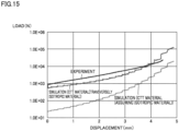
Fig. 15 is a view indicating an experimental result and a simulation result regarding a compression test for the CTT material. - An embodiment of the present invention will be described in detail with reference to the drawings. Note that the same or corresponding portions in the drawings are denoted by the same reference numerals, and redundant description thereof will not be repeated.
- A typical example of a composite material having out-of-plane anisotropy is fiber-reinforced plastic. In an embodiment of the present invention, a chopped carbon fiber tape reinforced thermoplastics (CTT) material that is a carbon fiber reinforced composite material is exemplified.
- The chopped carbon fiber tape reinforced thermoplastics (CTT) material is an intermediate base material in which resin-impregnated carbon fiber tapes are laminated. By laminating the carbon fiber tapes so that fibers are randomly oriented, the CTT material is manufactured. Thus, the CTT material has isotropy in a plane where fibers are oriented. On the other hand, the CTT material has anisotropy in an out-of-plane direction of the tapes, that is, in a direction in which tapes are laminated.
- In molding of the CTT material, flow in a direction in which chopped tapes are oriented (in-plane direction) and flow in a direction in which the chopped tapes are laminated (out-of-plane direction) exhibit different behaviors. Thus, in molding analysis of the CTT material, it is necessary to construct a model in which anisotropy is taken into account. Further, stress to be generated is different between in a lamination direction of the CTT material and a direction perpendicular to the lamination direction, and thus, in molding analysis of the CTT material, it is necessary to perform analysis in which anisotropy of stress tensor is taken into account.
- In the embodiment of the present invention, a model in which anisotropy of stress is indirectly taken into account using scalar quantity derived from stress tensor of anisotropy, specifically, using an equivalent viscosity, is used. Specifically, in the embodiment of the present invention, generalized stress tensor is introduced to calculate an average viscosity obtained by applying weight in accordance with a flow field. As application of weight in accordance with the flow field, arbitrary weighting can be applied. In one embodiment of the present invention, weighting based on orthogonal tensor decomposition is used.
- It is assumed that orientation of a material is expressed using an orthogonal coordinate system (t1, t2, n). If only n = (nx, ny, nz)T is obtained, a way of selection of t1 and t2 is not unique but can be expressed as in expression (2-1).


-
Fig. 1 is a view illustrating deformed states of a substance having in-plane isotropy. Note that as a substance having in-plane isotropy, a laminated body will be considered. As illustrated inFigs. 1(a) to 1(f) , there are six types of deformed states of the substance having in-plane isotropy, that is, (a) out-of-plane compression, (b) in-plane compression, (c) isotropic expansion, (d) and (e) out-of-plane shear, and (f) in-plane shear. -
Fig. 1 indicates three directions orthogonal to one another with arrows with reference numerals from "1 to "3". "Direction 1" and a direction (direction 2) perpendicular todirection 1 are set in an in-plane direction of the substance having in-plane isotropy, and a lamination direction of the substance (that is, an out-of-plane direction) is set as "direction 3". - A basis of symmetric tensor for the substance having in-plane isotropy can be expressed with expressions (2-3) to (2-8). Reference numerals (a) to (f) assigned ahead of the respective expressions respectively correspond to the reference numerals (a) to (f) indicated in
Fig. 1 . In expressions (2-3) to (2-8), R is a rotation matrix expressed as R = (t1, t2 n)T in a case where orientation of the substance is expressed using the orthogonal coordinate system (t1, t2, n). - Suffixes "1" to "3" to be used in expressions which will be described below are suffixes that respectively mean directions "1" to "3" illustrated in
Fig. 1 . Further, "⊥" means an out-of-plane direction, and "||" means an in-plane direction. - Tensor represents Ê ⊥: out-of-plane compression (
Fig. 1(a) ), Ê∥ : in-plane compression (Fig. 1(b) ), Î: isotropic expansion (Fig. 1(c) ), Ĝ 1 and Ĝ 2: out-of-plane shear (Fig. 1(d), Fig. 1(e) ), and Ĝ 3: in-plane shear (Fig. 1(f) ). - (a)

- (b)

- (c)

- (d)

- (e)

- (f)

- "
Direction 3" illustrated inFig. 1 is a lamination direction, and thus, a unit vector n in the lamination direction is provided by expression (2-9). In this event, R = I.
[Formula 3]
- Strain rate tensor D can be subjected to orthogonal tensor decomposition as expressed in expression (2-11) using a relationship (in which incompressibility is taken into account) of expression (2-10). In expression (2-11), ε with a dot (·) represents a strain rate.
[Formula 4]

- As expressed with expression (2-12), each strain rate is expressed by an inner product of basis tensor and strain rate tensor.
[Formula 5]
- An equivalent strain rate is provided by expression (2-13).
[Formula 6]
- Stress tensor σ can be expressed using basis tensor as in the following expression (2-14). Note that viscosity parameters are respectively an out-of-plane normal shear viscosity η⊥, an in-plane viscosity η∥, and an out-of-plane shear viscosity ηs, and p is a hydrostatic pressure.
[Formula 7]
- Expression (2-14) indicates that stress tensor σ is stress tensor in which anisotropy in the out-of-plane direction is taken into account. In the present specification, the stress tensor expressed with expression (2-14) will be referred to as "generalized stress tensor".
- An isotropic viscosity is obtained for the generalized stress tensor expressed with expression (2-14). The isotropic viscosity will be also referred to as an "average viscosity" in the present specification.
- To change a coefficient of each viscosity parameter and power in accordance with a form of flow, in the present embodiment, a weighting function depending on the flow field will be defined as provided in expression (3-1).
[Formula 8]

- Using the weighting function depending on the flow field, the isotropic viscosity can be expressed with expression (3-2).
[Formula 9]

- As described above, in the present embodiment, it is possible to isotropize and express the viscosity by using the generalized stress tensor and the weighting function that changes in accordance with a flow state. The isotropic viscosity (average viscosity) can be expressed in a form of a sum of a viscosity in the in-plane direction (in-plane viscosity) weighted depending on the flow field of the model, and a viscosity in the out-of-plane direction (an out-of-plane normal shear viscosity and an out-of-plane shear viscosity) weighted depending on the flow field of the model.
- In the present embodiment, flow upon molding of the composite material having anisotropy between the out-of-plane direction and the in-plane direction can be analyzed by calculating the isotropic viscosity (average viscosity) by a computer.
-
Fig. 2 is a view schematically explaining the intermediate base material to be analyzed and a manufacturing method of the intermediate base material according to the present embodiment. As illustrated inFig. 2 , anintermediate base material 10 contains aresin 12 andfibers 14. Directions indicated with reference numerals "1" to "3" inFig. 2 respectively correspond to the directions "1" to "3" illustrated inFig. 1 . -
Resin 12 may be a thermoplastic resin or a thermosetting resin, or the both may be used. While not limited, specific examples ofresin 12 can include a polyolefin resin such as polypropylene, a polyester resin, a polyamide resin, an epoxy resin, an unsaturated polyester resin, a phenol resin, a diallyl phthalate resin, a vinylester resin, a silicon resin, a polyimide resin, and the like. - Examples of
fibers 14 can include fibers typically used for fiber-reinforced plastic, for example, carbon fibers, glass fibers, boron fibers, silicon carbide fibers, alumina fibers, silica fibers, aromatic polyamide fibers, and the like. - In the present embodiment, a CTT material is used as an example of the intermediate base material. Thus,
Fig. 2 andFig. 3 illustrate an example of a manufacturing method of the CTT material as an example of the manufacturing method of the intermediate base material. An example of the manufacturing method of the CTT material will be described below with reference toFig. 2 andFig. 3 . -
Fig. 3 is a flowchart indicating an example of the manufacturing method of the CTT material. As indicated inFig. 2 andFig. 3 , first, a continuous fiber prepreg is manufactured (step S1). In step S1, a sheet-like base material (prepreg tape) is manufactured by impregnating a thermoplastic resin (for example, acid-modified polypropylene) with carbon fibers aligned in one direction. - Then, chopped tapes that are discontinuous fiber tapes are manufactured by cutting the prepreg tape into tapes of a predetermined size (step S2). While a size of the chopped tape is not particularly limited, in one example, the chopped tape has a size of, for example, a length of 35 mm, a width of 15 mm and a thickness of 0.1 mm.
- Subsequently, a plurality of chopped tapes are laminated. In this event, the plurality of chopped tapes are laminated so that
fibers 14 are randomly oriented in the in-plane direction. The laminated plurality of chopped tapes are compressed by application of heat and a pressure (step S3). By this means, the plurality of chopped tapes are integrated, and plate-likeintermediate base material 10 is manufactured. - As schematically illustrated in
Fig. 2 ,fibers 14 are randomly oriented in the in-plane direction. By this means, intermediate base material 10 (CTT material) has isotropy in the in-plane direction and anisotropy in the out-of-plane direction. As a result offibers 14 being oriented in the in-plane direction, flow ofintermediate base material 10 exhibits different behaviors between in the in-plane direction and in the out-of-plane direction. -
Fig. 4 is a flowchart indicating a molding method according to the present embodiment. As indicated inFig. 4 ,intermediate base material 10 is heated by a heating device such as an infrared heater. Then,intermediate base material 10 softened by heat is compressed within a mold. As a result of this, a molded article is manufactured. Note thatFig. 4 indicates stamping molding as an example of the molding method. In the stamping molding,intermediate base material 10 is pressed by a mold for stamping molding to become a molded article having a desired shape. -
Fig. 5 is a view illustrating an example of a configuration that can implement a molding analysis method according to the present embodiment. As illustrated inFig. 5 , for example, aheating device 22, amolding device 24 and ananalysis device 26 may be combined.Heating device 22, which is, for example, an infrared heater illustrated inFig. 4 , heatsintermediate base material 10.Molding device 24, which includes a mold 25 (for example, the mold for stamping molding illustrated inFig. 4 ), moldsintermediate base material 10 softened by heat. -
Analysis device 26, which is a device for executing the molding analysis method according to the present embodiment, is implemented by a program being executed by hardware in accordance with a versatile computing architecture.Analysis device 26 performs molding analysis ofintermediate base material 10 by executing simulation. -
Fig. 6 is a block diagram illustrating a hardware configuration example of the analysis device illustrated inFig. 5 .Analysis device 26 includes aprocessor 31, aprimary storage device 32, asecondary storage device 33, anexternal equipment interface 34, aninput interface 35, anoutput interface 36, acommunication interface 37, and abus 38. Components such asprocessor 31 andprimary storage device 32 exchange data, signals, and the like, throughbus 38. -
Processor 31 processes programs and data stored inprimary storage device 32.Primary storage device 32 stores the programs to be executed and data to be referred to byprocessor 31. In one aspect, a dynamic random access memory (DRAM) may be used asprimary storage device 32. -
Secondary storage device 33 stores programs, data, and the like, in a non-volatile manner. In one aspect, a non-volatile memory such as a hard disk drive (HDD) and a solid state drive (SSD) may be used assecondary storage device 33. Thus,secondary storage device 33 corresponds to a computer readable recording medium recording programs to be executed by a computer. -
External equipment interface 34 is used, for example, in a case where external equipment is connected toanalysis device 26.External equipment interface 34 is, for example, a universal serial bus (USB) interface. -
Input interface 35 is used to connect input devices such as akeyboard 41 and amouse 42.Input interface 35 accepts user operation and user input through these input devices. -
Output interface 36 is, for example, used to connect output devices such as adisplay 43. -
Communication interface 37 is used byanalysis device 26 to perform communication with external equipment. For example,communication interface 37 is used whenanalysis device 26 performs communication via a network. Communication with external equipment may be either wireless communication or wired communication. -
Analysis device 26 may include an optical drive as an option. The optical drive reads out a computer readable program stored in a recording medium (for example, an optical recording medium such as a digital versatile disc (DVD)) that transiently stores the program, from the recording medium. The program read out from the recording medium may be installed onsecondary storage device 33, or the like. Further, various kinds of programs to be executed atanalysis device 26 may be downloaded from a server device, or the like, on a network and may be installed onanalysis device 26. -
Fig. 7 is a view illustrating an example of functional blocks of the analysis device illustrated inFig. 5 . In one aspect,analysis device 26 as illustrated inFig. 7 is constituted by the hardware illustrated inFig. 6 executing software that implements functions of the respective functional blocks. Note thatanalysis device 26 may further include components other than the components illustrated inFig. 7 . - Referring to
Fig. 7 ,analysis device 26 includes aninput unit 51, an averageviscosity calculation unit 52, a viscositydistribution calculation unit 53, astorage unit 54, and anoutput unit 55.Input unit 51 accepts information such as material characteristics of a resin and molding conditions as input. These kinds of information are, for example, characteristic values of a molded article actually obtained by molding the intermediate base material in accordance with predetermined conditions, and the predetermined molding conditions. - Average
viscosity calculation unit 52 calculates an average viscosity that is an isotropic viscosity by applying a weighting function depending on a flow field to viscosities in an in-plane direction and in an out-of-plane direction of a model using the model having anisotropy between the out-of-plane direction and the in-plane direction orthogonal to the out-of-plane direction as a model ofintermediate base material 10. As the weighting function depending on the flow field, for example, weighting based on orthogonal tensor decomposition is used. - Viscosity
distribution calculation unit 53 performs molding analysis on finite elements of a molded article model obtained by modeling an actual molded article in accordance with predetermined molding conditions. Viscositydistribution calculation unit 53 obtains an average viscosity for each finite element of the model. The average viscosity is calculated by averageviscosity calculation unit 52. Viscositydistribution calculation unit 53 is a simulation execution unit that performs molding analysis. Averageviscosity calculation unit 52 may be included in viscositydistribution calculation unit 53 as part of viscositydistribution calculation unit 53. -
Storage unit 54 stores ananalysis program 61 for molding analysis, aparameter 62 for molding analysis input toanalysis device 26 from a user, and the like. Averageviscosity calculation unit 52 and viscositydistribution calculation unit 53 read outanalysis program 61 andparameter 62 fromstorage unit 54, executes molding analysis of the model and calculates an average viscosity for each finite element. By this means, averageviscosity calculation unit 52 and viscositydistribution calculation unit 53 calculate viscosity distribution in a cross-section direction of the molded article. -
Output unit 55 outputs the viscosity distribution in the cross-section direction of the molded article that is a calculation result of viscositydistribution calculation unit 53, as an analysis result. The analysis result is displayed at, for example, display 43 (seeFig. 6 ). - An experiment of molding of the CTT material will be described with reference to
Fig. 8 andFig. 9 .Fig. 8 is a schematic plan view of an experimental material.Fig. 9 is a schematic view of a molding experiment. As illustrated inFig. 8 andFig. 9 , a disc-like CTT material (corresponding to intermediate base material 10) to which a marking offline is provided is compressed under load using a compression test device under a condition that a resin temperature: 220°C, and compression speed: 3 mm/min. Note that to confirm that slip does not occur on a surface that is a wall surface contact portion of the CTT material, a marking offline 11 is formed on the surface of the CTT material, and viscosity characteristics are evaluated from compression load and velocity of compressive displacement. Values obtained in the experiment are input to a computer, and the computer performs molding analysis by executing a program using the input values. -
Fig. 10 is a view illustrating an analysis model created by a computer to simulate the molding experiment illustrated inFig. 8 andFig. 9 . As illustrated inFig. 10 , viscosity distribution in a state where a disc-like reinforced plastic base material is compressed under load is obtained through simulation. While software for executing simulation is not particularly limited, in the present example, analysis software 3D TIMON-CompositePRESS (Toray Engineering D Solutions Co., Ltd., "3D TIMON" and "CompositePRESS" are registered trademarks) is used. In the simulation, an average viscosity for each finite element is calculated. An equivalent strain rate is used as a weighting function for calculating the average viscosity. -
Fig. 11 is a first view indicating compression analysis results using the model illustrated inFig. 10 . As the analysis model, an isotropic material and a transversely isotropic material having anisotropy between the out-of-plane direction and the in-plane direction are used. Note thatFig. 11 is a view indicating results of studying a certain viscosity that does not depend on a shear rate for the isotropic material and the transversely isotropic material.Fig. 11(a) indicates viscosity distribution in a cross-section direction of the isotropic material, andFig. 1 1(b) indicates viscosity distribution in a cross-section direction of the transversely isotropic material. - For the isotropic material, the out-of-plane normal shear viscosity η⊥, the in-plane viscosity η∥, and the out-of-plane shear viscosity ηs are made the same (η⊥ = η∥ = ηs = 1E + 04Pa·s). On the other hand, for the transversely isotropic material, the out-of-plane normal shear viscosity η⊥ and the in-plane viscosity η∥ are made the same, and the out-of-plane shear viscosity ηs is made different from the out-of-plane normal shear viscosity η⊥ and the in-plane viscosity η∥ (η⊥ = η∥ = 1E + 07Pa·s, ηs = 1E + 04Pa·s). In this case, a result is obtained that a shear field is generated in the vicinity of a wall surface of a disc, and thus, influence of the out-of-plane shear viscosity that is a low viscosity increases in accordance with the shear field, and the viscosity in the vicinity of the wall surface becomes considerably lower than the viscosity at the central portion, thereby a lubricating layer is automatically generated.
- As indicated in
Fig. 11(b) , in a case of the transversely isotropic material, a large viscosity difference occurs between a portion near the center of the base material (disc) and a portion in the vicinity of the wall surface of the mold of the base material (disc). The "lubricating layer" refers to this area with a low viscosity. Note that "automatically" means not making a change to the boundary condition (No-slip), and not specifying a specific area (the vicinity of the wall surface of the mold or the center). -
Fig. 12 is a view indicating compression analysis results using the model illustrated inFig. 10 and is a view indicating an application example (viscosity distribution in a cross-section direction of the material) of the simulation to the CTT material.Fig. 12(a) is a view indicating viscosity distribution in a cross-section direction, obtained assuming that the CTT material is an isotropic material for comparison.Fig. 12(b) is a view indicating viscosity distribution in a cross-section of the CTT material (transversely isotropic material). - As can be seen from comparison of
Fig. 12(a) and Fig. 12(b) , in the CTT material (transversely isotropic material), a lubricating layer is prominently generated in the vicinity of the wall surface of the mold (that is, a viscosity difference is large between the center and the vicinity of the wall surface of the mold) compared to the assumed isotropic material. As a result, in a case where an actually measured anisotropic viscosity parameter in which the shear rate dependency is taken into account is used as in the CTT material, it can be seen that the lubricating layer prominently appears in an area in the vicinity of the wall surface of the mold upon molding. -
Fig. 13 is a view indicating analysis results of flow velocity distribution corresponding to the viscosity distribution indicated inFig. 11 .Fig. 14 is a view indicating analysis results of flow velocity distribution corresponding to the viscosity distribution indicated inFig. 12 . As can be seen fromFig. 11 to Fig. 14 , in the molding analysis method according to the present embodiment, as a viscosity ratio indicating intensity of anisotropy increases, a flow velocity in the vicinity of the wall surface of the mold comes closer to a flow velocity at the central portion of the molder article, and distribution of the flow velocity becomes closer to uniform in a thickness direction of the molded article. -
Fig. 15 is a view indicating an experimental result and a simulation result regarding a compression test for the CTT material. It can be seen fromFig. 15 that a value closer to the result of the experiment can be obtained in the simulation result of the CTT material (transversely isotropic material). In the simulation result in a case where an isotropic material is assumed for comparison, a value of load considerably lower than the experimental value is obtained. It can be seen from this that according to the present embodiment, a simulation result with high accuracy can be obtained in molding analysis regarding the CTT material. - Note that in the above-described embodiment, fiber-reinforced plastic is indicated as an example of a target material. However, the composite material that becomes a target in the present embodiment is not limited to fiber-reinforced plastic, and a composite material in which other types of reinforcing materials are added to a resin as a base material may be used. Examples of such reinforcing materials can include inorganic fillers such as cray and talc.
- Further, in the above-described embodiment, as a material having anisotropy between the out-of-plane direction and the in-plane direction, a transversely isotropic material is exemplified. However, the material having anisotropy between the out-of-plane direction and the in-plane direction is not limited to the transversely isotropic material and may be, for example, an in-plane isotropic material. The molding analysis method according to the present embodiment can be also applied to the in-plane isotropic material.
- While the embodiment and the examples of the present invention have been described above, it should be understood that the embodiments disclosed herein are by way of illustration and example only and are not to be taken by way of limitation. The scope of the present invention is indicated by the claims and is intended to include all changes within the content and the range equivalent to the claims.
- 10 Intermediate base material; 11 Marking off line; 12 Resin; 14 Fiber; 22 Heating device; 24 Molding device; 25 Mold; 26 Analysis device; 31 Processor; 32 Primary storage device; 33 Secondary storage device; 34 External equipment interface; 35 Input interface; 36 Output interface; 37 Communication interface; 38 Bus; 41 Keyboard; 43 Display; 51 Input unit; 52 Average viscosity calculation unit; 53 Viscosity distribution calculation unit; 54 Storage unit; 55 Output unit; S1 to S3 Step
Claims (9)
- A molding analysis method for performing molding analysis of a plate-like intermediate base material containing a resin and a reinforcing material when the intermediate base material is molded using a mold, the molding analysis method comprising:applying a model having anisotropy between an out-of-plane direction and an in-plane direction orthogonal to the out-of-plane direction as a model of the intermediate base material; andcalculating viscosity distribution in a cross-section direction of a molded article using each viscosity in accordance with a flow field,wherein the viscosity distribution indicates that under a boundary condition that there is no slip flow of the intermediate base material on a wall surface of the mold, as a result of a shear field occurring in the vicinity of the wall surface, a low viscosity layer that is more affected by an out-of-plane shear viscosity than a central portion of the intermediate base material is automatically formed in the vicinity of the wall surface, and the intermediate base material in the vicinity of the wall surface functions as a lubricating layer.
- The molding analysis method according to claim 1, comprisingmaking a flow velocity in the vicinity of the wall surface of the mold come closer to a flow velocity at a central portion of a molded article as a viscosity ratio indicating intensity of anisotropy increases, whereindistribution of the flow velocity becomes closer to uniform in a thickness direction of the molded article.
- The molding analysis method according to claim 1 or 2, comprising:
calculating an average velocity that is an isotropic velocity by applying a weighting function that depends on a flow field to viscosities in the in-plane direction and the out-of-plane direction of the model. - The molding analysis method according to claim 3,
wherein the weighting function is a function obtained on a basis of orthogonal tensor decomposition of strain rate tensor regarding deformation of the model. - The molding analysis method according to any one of claims 1 to 4,
wherein the flow field is out-of-plane compression, in-plane compression, isotropic compression, out-of-plane shear and in-plane shear. - The molding analysis method according to any one of claims 1 to 5,wherein the viscosity in the in-plane direction of the model is an in-plane viscosity, andthe viscosity in the out-of-plane direction of the model includes an out-of-plane normal shear viscosity and an out-of-plane shear viscosity.
- The molding analysis method according to any one of claims 1 to 6,
wherein the intermediate base material is fiber-reinforced plastic using a fiber as the reinforcing material. - A program for causing a computer to execute the molding analysis method according to any one of claims 1 to 7.
- A computer readable recording medium recording the program according to claim 8.
Applications Claiming Priority (2)
| Application Number | Priority Date | Filing Date | Title |
|---|---|---|---|
| JP2021093399 | 2021-06-03 | ||
| PCT/JP2022/022190 WO2022255380A1 (en) | 2021-06-03 | 2022-05-31 | Molding analysis method, program, and recording medium |
Publications (2)
| Publication Number | Publication Date |
|---|---|
| EP4350567A1 true EP4350567A1 (en) | 2024-04-10 |
| EP4350567A4 EP4350567A4 (en) | 2025-04-16 |
Family
ID=84323463
Family Applications (1)
| Application Number | Title | Priority Date | Filing Date |
|---|---|---|---|
| EP22816126.1A Withdrawn EP4350567A4 (en) | 2021-06-03 | 2022-05-31 | FORMULA ANALYSIS PROCEDURE, PROGRAM AND RECORDING MEDIUM |
Country Status (5)
| Country | Link |
|---|---|
| US (1) | US20240256739A1 (en) |
| EP (1) | EP4350567A4 (en) |
| JP (1) | JP7852884B2 (en) |
| TW (1) | TW202304687A (en) |
| WO (1) | WO2022255380A1 (en) |
Family Cites Families (5)
| Publication number | Priority date | Publication date | Assignee | Title |
|---|---|---|---|---|
| JP6684166B2 (en) * | 2016-06-21 | 2020-04-22 | 東レエンジニアリング株式会社 | Resin flow analysis method, program, and computer-readable recording medium |
| US10201921B1 (en) | 2018-02-01 | 2019-02-12 | Coretech System Co., Ltd. | Molding system for preparing fiber-reinforced thermoplastic composite article |
| JP2019159345A (en) * | 2018-03-07 | 2019-09-19 | 東洋紡株式会社 | Fiber-reinforced plastic analysis method |
| JP2019215204A (en) * | 2018-06-12 | 2019-12-19 | 東洋紡株式会社 | Viscosity characteristics evaluation method |
| US10201918B1 (en) * | 2018-07-05 | 2019-02-12 | Coretech System Co., Ltd. | Molding system for preparing fiber-reinforced thermoplastic composite article |
-
2022
- 2022-05-31 US US18/564,241 patent/US20240256739A1/en not_active Abandoned
- 2022-05-31 WO PCT/JP2022/022190 patent/WO2022255380A1/en not_active Ceased
- 2022-05-31 JP JP2023525871A patent/JP7852884B2/en active Active
- 2022-05-31 EP EP22816126.1A patent/EP4350567A4/en not_active Withdrawn
- 2022-06-02 TW TW111120540A patent/TW202304687A/en unknown
Also Published As
| Publication number | Publication date |
|---|---|
| EP4350567A4 (en) | 2025-04-16 |
| US20240256739A1 (en) | 2024-08-01 |
| WO2022255380A1 (en) | 2022-12-08 |
| JPWO2022255380A1 (en) | 2022-12-08 |
| TW202304687A (en) | 2023-02-01 |
| JP7852884B2 (en) | 2026-04-28 |
Similar Documents
| Publication | Publication Date | Title |
|---|---|---|
| Ballard et al. | The influence of microstructure randomness on prediction of fiber properties in composites | |
| Li et al. | A comparison of curing process-induced residual stresses and cure shrinkage in micro-scale composite structures with different constitutive laws | |
| JP6756997B2 (en) | A recording medium on which a finite element method analysis method, a finite element method analysis device, an analysis service system, and a finite element method analysis program are recorded. | |
| Dolkun et al. | Optimization of cure profile for thick composite parts based on finite element analysis and genetic algorithm | |
| Tavana et al. | Meso/macro-scale finite element model for forming process of woven fabric reinforcements | |
| US20130247360A1 (en) | Parametrized material and performance properties based on virtual testing | |
| Moradi-Dastjerdi et al. | Biaxial buckling analysis of functionally graded nanocomposite sandwich plates reinforced by aggregated carbon nanotube using improved high-order theory | |
| US9283695B1 (en) | Computer-implemented simulation method and non-transitory computer medium capable of predicting fiber orientation for use in a molding process | |
| Abu Al-Rub et al. | Application of a large deformation nonlinear-viscoelastic viscoplastic viscodamage constitutive model to polymers and their composites | |
| Luo et al. | Rapid prediction and inverse design of distortion behaviors of composite materials using artificial neural networks | |
| Jareteg et al. | Geometry assurance integrating process variation with simulation of spring-in for composite parts and assemblies | |
| Yao et al. | An anisotropic hyperelastic constitutive model for plain weave fabric considering biaxial tension coupling | |
| Rao et al. | Investigation of peel resistance during the fibre placement process | |
| EP2535828A1 (en) | Method for simulating the loss tangent of rubber compound | |
| Nawab et al. | Characterisation and modelling of thermal expansion coefficient of woven carbon/epoxy composite and its application to the determination of spring-in | |
| Hasanyan et al. | Micropolar constitutive relations for cellular solids | |
| Shaw | A note on the generalized thermoelasticity theory with memory-dependent derivatives | |
| Li et al. | Optimization of fiber-orientation distribution in fiber-reinforced composite injection molding by Taguchi, back propagation neural network, and genetic algorithm–particle swarm optimization | |
| Chu et al. | Placeability restricted by in-complete contact between laying roller and mould in an automated fiber placement process | |
| Matsuzaki et al. | Estimation of state and material properties during heat-curing molding of composite materials using data assimilation: A numerical study | |
| Zhai et al. | Multi-scale finite element simulation of the thermoforming of a woven fabric glass fiber/polyetherimide thermoplastic composite | |
| Zhai et al. | Experimental and numerical study of thermoforming-induced deformation in glass fiber/polyetherimide thermoplastic wing leading edge | |
| Sanei et al. | Effect of nanocomposite microstructure on stochastic elastic properties: an finite element analysis study | |
| Liu et al. | Simulation and analysis of process‐induced distortions in hemispherical thermostamping for unidirectional thermoplastic composites | |
| Fu et al. | A dual‐scale homogenization method to study the properties of chopped carbon fiber reinforced epoxy resin matrix composites |
Legal Events
| Date | Code | Title | Description |
|---|---|---|---|
| STAA | Information on the status of an ep patent application or granted ep patent |
Free format text: STATUS: THE INTERNATIONAL PUBLICATION HAS BEEN MADE |
|
| PUAI | Public reference made under article 153(3) epc to a published international application that has entered the european phase |
Free format text: ORIGINAL CODE: 0009012 |
|
| STAA | Information on the status of an ep patent application or granted ep patent |
Free format text: STATUS: REQUEST FOR EXAMINATION WAS MADE |
|
| 17P | Request for examination filed |
Effective date: 20240103 |
|
| AK | Designated contracting states |
Kind code of ref document: A1 Designated state(s): AL AT BE BG CH CY CZ DE DK EE ES FI FR GB GR HR HU IE IS IT LI LT LU LV MC MK MT NL NO PL PT RO RS SE SI SK SM TR |
|
| DAV | Request for validation of the european patent (deleted) | ||
| DAX | Request for extension of the european patent (deleted) | ||
| REG | Reference to a national code |
Ref country code: DE Ref legal event code: R079 Free format text: PREVIOUS MAIN CLASS: G06F0030230000 Ipc: B29C0045760000 |
|
| A4 | Supplementary search report drawn up and despatched |
Effective date: 20250318 |
|
| RIC1 | Information provided on ipc code assigned before grant |
Ipc: G06F 113/08 20200101ALN20250312BHEP Ipc: G06F 111/10 20200101ALN20250312BHEP Ipc: G06F 30/00 20200101ALI20250312BHEP Ipc: G06F 113/26 20200101ALI20250312BHEP Ipc: G06F 113/22 20200101ALI20250312BHEP Ipc: G06F 30/23 20200101ALI20250312BHEP Ipc: B29C 33/38 20060101ALI20250312BHEP Ipc: B29C 45/76 20060101AFI20250312BHEP |
|
| STAA | Information on the status of an ep patent application or granted ep patent |
Free format text: STATUS: THE APPLICATION IS DEEMED TO BE WITHDRAWN |
|
| 18D | Application deemed to be withdrawn |
Effective date: 20251007 |