EP4350497A1 - Display control device and display control method - Google Patents
Display control device and display control method Download PDFInfo
- Publication number
- EP4350497A1 EP4350497A1 EP21848126.5A EP21848126A EP4350497A1 EP 4350497 A1 EP4350497 A1 EP 4350497A1 EP 21848126 A EP21848126 A EP 21848126A EP 4350497 A1 EP4350497 A1 EP 4350497A1
- Authority
- EP
- European Patent Office
- Prior art keywords
- tile
- icon
- display
- controller
- user
- Prior art date
- Legal status (The legal status is an assumption and is not a legal conclusion. Google has not performed a legal analysis and makes no representation as to the accuracy of the status listed.)
- Granted
Links
Images




Classifications
-
- G—PHYSICS
- G06—COMPUTING OR CALCULATING; COUNTING
- G06F—ELECTRIC DIGITAL DATA PROCESSING
- G06F3/00—Input arrangements for transferring data to be processed into a form capable of being handled by the computer; Output arrangements for transferring data from processing unit to output unit, e.g. interface arrangements
- G06F3/01—Input arrangements or combined input and output arrangements for interaction between user and computer
- G06F3/048—Interaction techniques based on graphical user interfaces [GUI]
- G06F3/0481—Interaction techniques based on graphical user interfaces [GUI] based on specific properties of the displayed interaction object or a metaphor-based environment, e.g. interaction with desktop elements like windows or icons, or assisted by a cursor's changing behaviour or appearance
-
- G—PHYSICS
- G06—COMPUTING OR CALCULATING; COUNTING
- G06F—ELECTRIC DIGITAL DATA PROCESSING
- G06F3/00—Input arrangements for transferring data to be processed into a form capable of being handled by the computer; Output arrangements for transferring data from processing unit to output unit, e.g. interface arrangements
- G06F3/01—Input arrangements or combined input and output arrangements for interaction between user and computer
- G06F3/048—Interaction techniques based on graphical user interfaces [GUI]
- G06F3/0481—Interaction techniques based on graphical user interfaces [GUI] based on specific properties of the displayed interaction object or a metaphor-based environment, e.g. interaction with desktop elements like windows or icons, or assisted by a cursor's changing behaviour or appearance
- G06F3/04817—Interaction techniques based on graphical user interfaces [GUI] based on specific properties of the displayed interaction object or a metaphor-based environment, e.g. interaction with desktop elements like windows or icons, or assisted by a cursor's changing behaviour or appearance using icons
-
- B—PERFORMING OPERATIONS; TRANSPORTING
- B60—VEHICLES IN GENERAL
- B60K—ARRANGEMENT OR MOUNTING OF PROPULSION UNITS OR OF TRANSMISSIONS IN VEHICLES; ARRANGEMENT OR MOUNTING OF PLURAL DIVERSE PRIME-MOVERS IN VEHICLES; AUXILIARY DRIVES FOR VEHICLES; INSTRUMENTATION OR DASHBOARDS FOR VEHICLES; ARRANGEMENTS IN CONNECTION WITH COOLING, AIR INTAKE, GAS EXHAUST OR FUEL SUPPLY OF PROPULSION UNITS IN VEHICLES
- B60K35/00—Instruments specially adapted for vehicles; Arrangement of instruments in or on vehicles
- B60K35/10—Input arrangements, i.e. from user to vehicle, associated with vehicle functions or specially adapted therefor
-
- B—PERFORMING OPERATIONS; TRANSPORTING
- B60—VEHICLES IN GENERAL
- B60K—ARRANGEMENT OR MOUNTING OF PROPULSION UNITS OR OF TRANSMISSIONS IN VEHICLES; ARRANGEMENT OR MOUNTING OF PLURAL DIVERSE PRIME-MOVERS IN VEHICLES; AUXILIARY DRIVES FOR VEHICLES; INSTRUMENTATION OR DASHBOARDS FOR VEHICLES; ARRANGEMENTS IN CONNECTION WITH COOLING, AIR INTAKE, GAS EXHAUST OR FUEL SUPPLY OF PROPULSION UNITS IN VEHICLES
- B60K35/00—Instruments specially adapted for vehicles; Arrangement of instruments in or on vehicles
- B60K35/20—Output arrangements, i.e. from vehicle to user, associated with vehicle functions or specially adapted therefor
- B60K35/21—Output arrangements, i.e. from vehicle to user, associated with vehicle functions or specially adapted therefor using visual output, e.g. blinking lights or matrix displays
- B60K35/22—Display screens
-
- G—PHYSICS
- G06—COMPUTING OR CALCULATING; COUNTING
- G06F—ELECTRIC DIGITAL DATA PROCESSING
- G06F3/00—Input arrangements for transferring data to be processed into a form capable of being handled by the computer; Output arrangements for transferring data from processing unit to output unit, e.g. interface arrangements
- G06F3/01—Input arrangements or combined input and output arrangements for interaction between user and computer
- G06F3/048—Interaction techniques based on graphical user interfaces [GUI]
- G06F3/0481—Interaction techniques based on graphical user interfaces [GUI] based on specific properties of the displayed interaction object or a metaphor-based environment, e.g. interaction with desktop elements like windows or icons, or assisted by a cursor's changing behaviour or appearance
- G06F3/0482—Interaction with lists of selectable items, e.g. menus
-
- G—PHYSICS
- G06—COMPUTING OR CALCULATING; COUNTING
- G06F—ELECTRIC DIGITAL DATA PROCESSING
- G06F3/00—Input arrangements for transferring data to be processed into a form capable of being handled by the computer; Output arrangements for transferring data from processing unit to output unit, e.g. interface arrangements
- G06F3/01—Input arrangements or combined input and output arrangements for interaction between user and computer
- G06F3/048—Interaction techniques based on graphical user interfaces [GUI]
- G06F3/0484—Interaction techniques based on graphical user interfaces [GUI] for the control of specific functions or operations, e.g. selecting or manipulating an object, an image or a displayed text element, setting a parameter value or selecting a range
- G06F3/04845—Interaction techniques based on graphical user interfaces [GUI] for the control of specific functions or operations, e.g. selecting or manipulating an object, an image or a displayed text element, setting a parameter value or selecting a range for image manipulation, e.g. dragging, rotation, expansion or change of colour
-
- G—PHYSICS
- G06—COMPUTING OR CALCULATING; COUNTING
- G06F—ELECTRIC DIGITAL DATA PROCESSING
- G06F3/00—Input arrangements for transferring data to be processed into a form capable of being handled by the computer; Output arrangements for transferring data from processing unit to output unit, e.g. interface arrangements
- G06F3/01—Input arrangements or combined input and output arrangements for interaction between user and computer
- G06F3/048—Interaction techniques based on graphical user interfaces [GUI]
- G06F3/0484—Interaction techniques based on graphical user interfaces [GUI] for the control of specific functions or operations, e.g. selecting or manipulating an object, an image or a displayed text element, setting a parameter value or selecting a range
- G06F3/0485—Scrolling or panning
-
- G—PHYSICS
- G06—COMPUTING OR CALCULATING; COUNTING
- G06F—ELECTRIC DIGITAL DATA PROCESSING
- G06F3/00—Input arrangements for transferring data to be processed into a form capable of being handled by the computer; Output arrangements for transferring data from processing unit to output unit, e.g. interface arrangements
- G06F3/01—Input arrangements or combined input and output arrangements for interaction between user and computer
- G06F3/048—Interaction techniques based on graphical user interfaces [GUI]
- G06F3/0484—Interaction techniques based on graphical user interfaces [GUI] for the control of specific functions or operations, e.g. selecting or manipulating an object, an image or a displayed text element, setting a parameter value or selecting a range
- G06F3/0486—Drag-and-drop
-
- G—PHYSICS
- G06—COMPUTING OR CALCULATING; COUNTING
- G06F—ELECTRIC DIGITAL DATA PROCESSING
- G06F3/00—Input arrangements for transferring data to be processed into a form capable of being handled by the computer; Output arrangements for transferring data from processing unit to output unit, e.g. interface arrangements
- G06F3/01—Input arrangements or combined input and output arrangements for interaction between user and computer
- G06F3/048—Interaction techniques based on graphical user interfaces [GUI]
- G06F3/0487—Interaction techniques based on graphical user interfaces [GUI] using specific features provided by the input device, e.g. functions controlled by the rotation of a mouse with dual sensing arrangements, or of the nature of the input device, e.g. tap gestures based on pressure sensed by a digitiser
- G06F3/0488—Interaction techniques based on graphical user interfaces [GUI] using specific features provided by the input device, e.g. functions controlled by the rotation of a mouse with dual sensing arrangements, or of the nature of the input device, e.g. tap gestures based on pressure sensed by a digitiser using a touch-screen or digitiser, e.g. input of commands through traced gestures
-
- G—PHYSICS
- G06—COMPUTING OR CALCULATING; COUNTING
- G06F—ELECTRIC DIGITAL DATA PROCESSING
- G06F3/00—Input arrangements for transferring data to be processed into a form capable of being handled by the computer; Output arrangements for transferring data from processing unit to output unit, e.g. interface arrangements
- G06F3/01—Input arrangements or combined input and output arrangements for interaction between user and computer
- G06F3/048—Interaction techniques based on graphical user interfaces [GUI]
- G06F3/0487—Interaction techniques based on graphical user interfaces [GUI] using specific features provided by the input device, e.g. functions controlled by the rotation of a mouse with dual sensing arrangements, or of the nature of the input device, e.g. tap gestures based on pressure sensed by a digitiser
- G06F3/0488—Interaction techniques based on graphical user interfaces [GUI] using specific features provided by the input device, e.g. functions controlled by the rotation of a mouse with dual sensing arrangements, or of the nature of the input device, e.g. tap gestures based on pressure sensed by a digitiser using a touch-screen or digitiser, e.g. input of commands through traced gestures
- G06F3/04883—Interaction techniques based on graphical user interfaces [GUI] using specific features provided by the input device, e.g. functions controlled by the rotation of a mouse with dual sensing arrangements, or of the nature of the input device, e.g. tap gestures based on pressure sensed by a digitiser using a touch-screen or digitiser, e.g. input of commands through traced gestures for inputting data by handwriting, e.g. gesture or text
-
- G—PHYSICS
- G06—COMPUTING OR CALCULATING; COUNTING
- G06F—ELECTRIC DIGITAL DATA PROCESSING
- G06F3/00—Input arrangements for transferring data to be processed into a form capable of being handled by the computer; Output arrangements for transferring data from processing unit to output unit, e.g. interface arrangements
- G06F3/01—Input arrangements or combined input and output arrangements for interaction between user and computer
- G06F3/048—Interaction techniques based on graphical user interfaces [GUI]
- G06F3/0487—Interaction techniques based on graphical user interfaces [GUI] using specific features provided by the input device, e.g. functions controlled by the rotation of a mouse with dual sensing arrangements, or of the nature of the input device, e.g. tap gestures based on pressure sensed by a digitiser
- G06F3/0488—Interaction techniques based on graphical user interfaces [GUI] using specific features provided by the input device, e.g. functions controlled by the rotation of a mouse with dual sensing arrangements, or of the nature of the input device, e.g. tap gestures based on pressure sensed by a digitiser using a touch-screen or digitiser, e.g. input of commands through traced gestures
- G06F3/04886—Interaction techniques based on graphical user interfaces [GUI] using specific features provided by the input device, e.g. functions controlled by the rotation of a mouse with dual sensing arrangements, or of the nature of the input device, e.g. tap gestures based on pressure sensed by a digitiser using a touch-screen or digitiser, e.g. input of commands through traced gestures by partitioning the display area of the touch-screen or the surface of the digitising tablet into independently controllable areas, e.g. virtual keyboards or menus
-
- B—PERFORMING OPERATIONS; TRANSPORTING
- B60—VEHICLES IN GENERAL
- B60K—ARRANGEMENT OR MOUNTING OF PROPULSION UNITS OR OF TRANSMISSIONS IN VEHICLES; ARRANGEMENT OR MOUNTING OF PLURAL DIVERSE PRIME-MOVERS IN VEHICLES; AUXILIARY DRIVES FOR VEHICLES; INSTRUMENTATION OR DASHBOARDS FOR VEHICLES; ARRANGEMENTS IN CONNECTION WITH COOLING, AIR INTAKE, GAS EXHAUST OR FUEL SUPPLY OF PROPULSION UNITS IN VEHICLES
- B60K2360/00—Indexing scheme associated with groups B60K35/00 or B60K37/00 relating to details of instruments or dashboards
- B60K2360/11—Instrument graphical user interfaces or menu aspects
-
- B—PERFORMING OPERATIONS; TRANSPORTING
- B60—VEHICLES IN GENERAL
- B60K—ARRANGEMENT OR MOUNTING OF PROPULSION UNITS OR OF TRANSMISSIONS IN VEHICLES; ARRANGEMENT OR MOUNTING OF PLURAL DIVERSE PRIME-MOVERS IN VEHICLES; AUXILIARY DRIVES FOR VEHICLES; INSTRUMENTATION OR DASHBOARDS FOR VEHICLES; ARRANGEMENTS IN CONNECTION WITH COOLING, AIR INTAKE, GAS EXHAUST OR FUEL SUPPLY OF PROPULSION UNITS IN VEHICLES
- B60K2360/00—Indexing scheme associated with groups B60K35/00 or B60K37/00 relating to details of instruments or dashboards
- B60K2360/11—Instrument graphical user interfaces or menu aspects
- B60K2360/113—Scrolling through menu items
-
- B—PERFORMING OPERATIONS; TRANSPORTING
- B60—VEHICLES IN GENERAL
- B60K—ARRANGEMENT OR MOUNTING OF PROPULSION UNITS OR OF TRANSMISSIONS IN VEHICLES; ARRANGEMENT OR MOUNTING OF PLURAL DIVERSE PRIME-MOVERS IN VEHICLES; AUXILIARY DRIVES FOR VEHICLES; INSTRUMENTATION OR DASHBOARDS FOR VEHICLES; ARRANGEMENTS IN CONNECTION WITH COOLING, AIR INTAKE, GAS EXHAUST OR FUEL SUPPLY OF PROPULSION UNITS IN VEHICLES
- B60K2360/00—Indexing scheme associated with groups B60K35/00 or B60K37/00 relating to details of instruments or dashboards
- B60K2360/143—Touch sensitive instrument input devices
- B60K2360/1438—Touch screens
-
- B—PERFORMING OPERATIONS; TRANSPORTING
- B60—VEHICLES IN GENERAL
- B60K—ARRANGEMENT OR MOUNTING OF PROPULSION UNITS OR OF TRANSMISSIONS IN VEHICLES; ARRANGEMENT OR MOUNTING OF PLURAL DIVERSE PRIME-MOVERS IN VEHICLES; AUXILIARY DRIVES FOR VEHICLES; INSTRUMENTATION OR DASHBOARDS FOR VEHICLES; ARRANGEMENTS IN CONNECTION WITH COOLING, AIR INTAKE, GAS EXHAUST OR FUEL SUPPLY OF PROPULSION UNITS IN VEHICLES
- B60K2360/00—Indexing scheme associated with groups B60K35/00 or B60K37/00 relating to details of instruments or dashboards
- B60K2360/146—Instrument input by gesture
- B60K2360/1468—Touch gesture
Definitions
- the present invention relates to a display control device and a display control method.
- Patent Document 1 An invention for searching for a target display item from a scroll display is known from the prior art (Patent Document 1).
- Patent Document 1 when an item matching a prescribed search condition is displayed on a screen, the scroll display is controlled to be a slower speed than usual.
- Patent Document 1 Japanese Laid Open Patent Application No. 2012-230571
- an object of the present invention is to provide a display control device and a display control method that can emphasize that an icon is displayed in front of a tile on a screen.
- a display control device detects a start trigger indicating that a user has started scrolling to the left or a right on a display, increases the relative position between a tile and an icon at a prescribed acceleration with the passage of time from the detected start trigger, detects a stop trigger indicating that the user has stopped scrolling, and reduces the relative position between the tile and the icon at a prescribed deceleration with the passage of time from the detected stop trigger.
- a screen is one on which an icon is displayed in front of a tile.
- the display control device 1 is installed in a vehicle. As shown in Figure 1 , the display control device 1 comprises a controller 10 and a display 11. The display 11 is a touch panel capable of touch operation.
- the controller 10 controls an image displayed on the display 11.
- the controller 10 is a general-purpose microcomputer comprising a CPU (central processing device), memory, and an input/output unit.
- a computer program is installed in the microcomputer to cause it to function as the display control device 1.
- the microcomputer functions as a plurality of information processing circuits included in the display control device 1.
- the plurality of information processing circuits included in the display control device 1 is realized by software, but the information processing circuits can of course comprise dedicated hardware for executing each of the information processes shown below.
- the plurality of information processing circuits may be realized by discrete hardware.
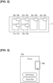
- FIG. 2 One example of an image that is displayed on the display 11 will be described next with reference to Figure 2 .
- a plurality of tiles 20a-25a are displayed on the display 11.
- a tile is an image for activating an application.
- a user touches a tile to thereby activate a desired application.
- Types of applications include phone, route guidance, video playback, and music playback.
- an icon relating to the tile is displayed on each tile.
- an icon 20b is displayed as overlapping a tile 20a.
- a part of the icon 20b overlaps the tile 20a, but is not limited thereto.
- the entire icon 20b may overlap the tile 20a. It is sufficient if at least a part of the icon 20b overlaps the tile 20a.
- icons 21b-25b overlap at the upper right of the tiles 20a-25a, but the present invention is not limited thereto.
- the shape of the icon and the tile is rectangular, but the shape is not limited thereto, and may be circular.
- the tile 24a and the icon 24b are taken as representative examples from among the plurality of tiles and icons.
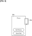
- the images "Call History" and “Quick Dial" are included in the tile 24a. If the user touches "Call History,” the call history is displayed. If the user touches "Quick Dial,” the last called number is called.
- the shape of the icon 24b is that of a smartphone. That is, the icon 24b has a shape relating to the tile 24a (phone).
- the icon 24b is an image that can indicate, to the user, information relating to the application (the one that is activated by touching the tile 24a).
- an image related to the currently playing musical piece may be employed as the icon.
- the position of the icon 24b is different between Figure 2 and Figure 3 . This is to explain that the position of the icon 24b is not limited.
- "Scrolling” is a method for displaying content that does not fit the screen by sliding horizontally or vertically. "Scrolling” is a well-known technique, and is mainly used in smartphones, tablet terminals, and the like. In the present embodiment, the direction in which the user scrolls is the horizontal direction (left-right direction) of the display 11, as shown in Figure 4 .
- a relative position is the relative position of one as viewed from the other.
- the relative position is expressed in terms of distance.
- the relative position is defined as "the distance to the icon as viewed from the tile.” More specifically, the relative position is defined as the "shortest distance to a center line of the icon as viewed from a center line of the tile.” In Figure 4 , the "shortest distance to the center line of the icon as viewed from the center line of the tile" is indicated by the reference symbol L1. Thus, the relative position between the tile 24a and the icon 24b is expressed as the shortest distance L1 to the center line of the icon 24b as viewed from the center line of the tile 24a.
- the center line means a conceptual line. The center line is not actually displayed on the display 11. Although there is only one reference symbol L1 indicating the relative position in Figure 4 , this is simply because the other ones are omitted.
- the definition of the relative position is the same for the tiles 20a-23a, 25a and the icons 20b-23b, 25b.
- the relative distance L1 between the tile 24a and the icon 24b is "1."
- This numerical value "1" is a standardized numerical value. Such standardized numerical values include some errors, but the errors are minimal.
- the relative distance between the tile 24a and the icon 24b is indicated by the reference symbol 50.
- the controller 10 moves the tile 24a to the left at a prescribed acceleration.
- the reference symbol 30 (lateral position "0") moves to the reference symbol 31 (lateral position "0.5”). This indicates that the tile 24a is moving to the left at a prescribed acceleration (refer to Figure 4 ).
- the controller 10 moves the tile 24a first.
- the relative distance between the tile 24a and the icon 24b thereby increases.
- the relative distance after the increase is indicated by the reference symbol L2 in Figure 4 .
- the reference symbol 31 moves to the reference symbol 32 (lateral position "2.2"). This indicates that the tile 24a is continuing to move to the left at a prescribed acceleration.
- the reference symbol 41 moves to the reference symbol 42 (lateral position "-0.5").
- the icon 24b is moving to the left at a prescribed acceleration. That is, the controller 10 first moves the tile 24a to the left, and then moves the icon 24b to the left. The acceleration at which the tile 24a is moved is greater than the acceleration at which the icon 24b is moved.
- the reference symbol 32 (lateral position "2.2") moves to the reference symbol 33 (lateral position "4.2”). This indicates that the tile 24a is moving to the left at a prescribed speed.
- the reference symbol 42 (lateral position "-0.5") moves to the reference symbol 43 (lateral position "1 "). This indicates that the icon 24b is continuing to move to the left at a prescribed acceleration.
- the reference symbol 33 (lateral position "4.2") moves to the reference symbol 34 (lateral position "6.4"). This indicates that the tile 24a is continuing to move to the left at a prescribed speed.
- the reference symbol 43 (lateral position "1") moves to the reference symbol 44 (lateral position "3.2”). This indicates that the icon 24b is moving to the left at a speed.
- the controller 10 decelerates and stops the tile 24a and the icon 24b.
- the reference symbol 34 lateral position "6.4 ” moves to the reference symbol 35 (lateral position "8.2"). This indicates that the tile 24a is moving to the left at a prescribed deceleration.
- the reference symbol 44 (lateral position "3.2") moves to the reference symbol 45 (lateral position "5.4").
- the controller 10 decelerates the tile 24a first.
- the relative distance between the tile 24a and the icon 24b thereby decreases.
- the relative distance after the decrease is indicated by the reference symbol "L3" in Figure 6 .
- the controller 10 decelerates the tile 24a first, thereby decreasing the relative distance between the tile 24a and the icon 24b from "L2" (3.2) to "L3" (2.8).
- the reference symbol 35 (lateral position "8.2") moves to the reference symbol 36 (lateral position "9.5"). This indicates that the tile 24a is continuing to move to the left at a prescribed deceleration.
- the reference symbol 45 (lateral position "5.4") moves to the reference symbol 46 (lateral position "7").
- the reference symbol 36 (lateral position "9.5") moves to the reference symbol 37 (lateral position "10.1"). This indicates that the tile 24a is continuing to move to the left at a prescribed deceleration.
- the reference symbol 46 (lateral position "7") moves to the reference symbol 47 (lateral position "8.2”). This indicates that the icon 24b is continuing to move to the left at a prescribed deceleration.
- the reference symbol 37 (lateral position "10.1") moves to the reference symbol 38 (lateral position "10.2"). This indicates that the tile 24a is continuing to move to the left at a prescribed deceleration.
- the reference symbol 47 (lateral position "8.2") moves to the reference symbol 48 (lateral position "8.9”). This indicates that the icon 24b is continuing to move to the left at a prescribed deceleration.
- the relative position between the tile 24a and the icon 24b is indicated by a quadratic function.
- the values of the acceleration, speed, and deceleration described in Figure 7 can be changed as appropriate.
- the curve shown in Figure 7 can be changed as appropriate as long as the curve can be represented by a quadratic function.
- the "relative position" and the “relative distance” described above are merely slight differences in expression and the intentions thereof are the same.
- Step S101 the controller 10 detects a start trigger indicating that the user has started scrolling to the left or the right on the display 11. As described above, the method for detecting such a start trigger is well known. If a start trigger is detected (YES in Step S101), the process proceeds to Step S103. In Step S103, the controller 10 increases the relative positions between the tiles 20a-25a and the icons 20b-25b. The increase control is carried out until a scroll stop is detected (NO in Step S105). If a scroll stop is detected (YES in Step S105), the controller 10 decreases and returns the relative positions between the tiles 20a-25a and the icons 20b-25b to the original relative positions.
- the display control device 1 comprises the display 11 that is capable of touch operation and the controller 10 that controls an image displayed on the display 11.
- the display 11 and the controller 10 are installed in a vehicle.
- a tile that activates an application by means of a user's touch, and an icon related to the application are displayed on the display 11. At least a part of the icon is displayed as overlapping the tile.
- the controller 10 detects a start trigger indicating that the user has started scrolling to the left or right on the display 11.
- the controller 10 increases the relative position between the tile and the icon at a prescribed acceleration with the passage of time from the detected start trigger.
- the controller 10 detects a stop trigger indicating that the user has stopped scrolling.
- the controller 10 decreases the relative position between the tile and the icon at a prescribed deceleration with the passage of time from the detected stop trigger.
- the passage of time from the detected start trigger means the time elapsed while the user is scrolling.
- the passage of time from the detected stop trigger means the time elapsed after the user stopped scrolling.
- the prescribed acceleration and the prescribed deceleration can be obtained in advance by means of experimentation and simulation.
- the pair of tiles and icons may be one pair, or a plurality of pairs. In the present embodiment, the pair of tiles and icons has been described as a plurality of pairs.
- the relative position between the tile and the icon is represented by a quadratic function (refer to Figure 7 ).
- the parallax effect is thereby improved.
- a plurality of tiles and icons are displayed on the display 11.
- the controller 10 may increase the distance between adjacent tiles at a prescribed acceleration with the passage of time from the detected start trigger.
- An example of adjacent tiles are the tile 24a and the tile 25a shown in Figure 4 .
- the controller 10 may reduce the distance between adjacent tiles at a prescribed deceleration with the passage of time from the detected stop trigger.
- the controller 10 moves the tile first at a prescribed acceleration and then moves the icon at a prescribed acceleration. It is thereby possible to emphasize the fact that the image is one in which an icon is displayed in front of a tile.
- the controller 10 may decrease the relative position between the tile and the icon. The controller 10 then stops the movement of the tile and the icon. Next, the controller 10 moves the tile and the icon in a different direction at a prescribed acceleration, to thereby increase the relative position between the tile and the icon. It is thereby possible to emphasize that the image is one in which an icon is displayed in front of a tile in accordance with the scrolling direction.
- the "different direction” used herein means the right direction, for example, if the user first scrolls to the left and then scrolls to the right.
- the controller 10 may tilt the orientation of the tile in the direction of movement. The parallax effect is thereby improved.
- the center position of the tile and the center position of the icon do not coincide in the horizontal direction of the display 11.
- the icons may be disposed at any position.
- the stop trigger is a detection signal indicating that the user has removed the finger from the display 11.
- the controller 10 may increase the prescribed acceleration or the prescribed deceleration, as the speed or acceleration of the user's scrolling increases. The parallax effect is thereby improved.
- the controller 10 may increase the maximum value of the relative position, as the speed or acceleration of the user's scrolling increases.
- the maximum value of the relative position is described as “3.2,” but this "3.2" may be increased as the speed or acceleration of the user's scrolling increases. The parallax effect is thereby improved.
- processing circuits include programmed processing devices, such as processing devices including electrical circuits.
- processing circuits include devices such as circuit components and application specific integrated circuits (ASIC) arranged to execute the described functions.
- ASIC application specific integrated circuits
Landscapes
- Engineering & Computer Science (AREA)
- General Engineering & Computer Science (AREA)
- Theoretical Computer Science (AREA)
- Human Computer Interaction (AREA)
- Physics & Mathematics (AREA)
- General Physics & Mathematics (AREA)
- Chemical & Material Sciences (AREA)
- Combustion & Propulsion (AREA)
- Transportation (AREA)
- Mechanical Engineering (AREA)
- User Interface Of Digital Computer (AREA)
- Controls And Circuits For Display Device (AREA)
Abstract
Description
- The present invention relates to a display control device and a display control method.
- An invention for searching for a target display item from a scroll display is known from the prior art (Patent Document 1). In the invention disclosed in
Patent Document 1, when an item matching a prescribed search condition is displayed on a screen, the scroll display is controlled to be a slower speed than usual. - Patent Document 1:
Japanese Laid Open Patent Application No. 2012-230571 - However, in the invention disclosed in
Patent Document 1, the rendering of a parallax effect on the screen on which icons are displayed in front of tiles is insufficient. - In view of the problem described above, an object of the present invention is to provide a display control device and a display control method that can emphasize that an icon is displayed in front of a tile on a screen.
- A display control device according to one aspect of the present invention detects a start trigger indicating that a user has started scrolling to the left or a right on a display, increases the relative position between a tile and an icon at a prescribed acceleration with the passage of time from the detected start trigger, detects a stop trigger indicating that the user has stopped scrolling, and reduces the relative position between the tile and the icon at a prescribed deceleration with the passage of time from the detected stop trigger.
- By means of the present invention, it is possible to emphasize the fact that a screen is one on which an icon is displayed in front of a tile.
-
-
Figure 1 is a configuration diagram of adisplay control device 1 according to an embodiment of the present invention. -
Figure 2 is a diagram for explaining an example of an image displayed on adisplay 11. -
Figure 3 is a diagram for explaining an example of atile 24a and anicon 24b. -
Figure 4 is a diagram for explaining an example of movement oftiles 20a-25a andicons 20b-25b. -
Figure 5 is a diagram for explaining an example of thetile 24a and theicon 24b. -
Figure 6 is a diagram for explaining an example of the movement of thetiles 20a-25a and theicons 20b-25b. -
Figure 7 is a diagram for explaining an example of the movement of thetiles 20a-25a and theicons 20b-25b. -
Figure 8 is a flowchart showing an example of an operation of thedisplay control device 1 according to the embodiment of the present invention. - An embodiment of the present invention is described below with reference to the drawings. In the descriptions of the drawings, identical parts have been assigned the same reference numerals, and the descriptions thereof have been omitted.
- A configuration example of a
display control device 1 will be described with reference toFigure 1 . Thedisplay control device 1 is installed in a vehicle. As shown inFigure 1 , thedisplay control device 1 comprises acontroller 10 and adisplay 11. Thedisplay 11 is a touch panel capable of touch operation. - The
controller 10 controls an image displayed on thedisplay 11. Thecontroller 10 is a general-purpose microcomputer comprising a CPU (central processing device), memory, and an input/output unit. A computer program is installed in the microcomputer to cause it to function as thedisplay control device 1. By executing the computer program, the microcomputer functions as a plurality of information processing circuits included in thedisplay control device 1. Here, an example is shown in which the plurality of information processing circuits included in thedisplay control device 1 is realized by software, but the information processing circuits can of course comprise dedicated hardware for executing each of the information processes shown below. In addition, the plurality of information processing circuits may be realized by discrete hardware. - One example of an image that is displayed on the
display 11 will be described next with reference toFigure 2 . As shown inFigure 2 , a plurality oftiles 20a-25a are displayed on thedisplay 11. A tile is an image for activating an application. A user touches a tile to thereby activate a desired application. Types of applications include phone, route guidance, video playback, and music playback. - An icon relating to the tile (application) is displayed on each tile. In the present embodiment, as shown in
Figure 2 , anicon 20b is displayed as overlapping atile 20a. InFigure 2 , a part of theicon 20b overlaps thetile 20a, but is not limited thereto. Theentire icon 20b may overlap thetile 20a. It is sufficient if at least a part of theicon 20b overlaps thetile 20a. The same applies toicons 21b-25b. InFigure 2 , theicons 20b-25b overlap at the upper right of thetiles 20a-25a, but the present invention is not limited thereto. In addition, the shape of the icon and the tile is rectangular, but the shape is not limited thereto, and may be circular. - In the description above, it is described that a phone is included in the application type, but a specific example thereof will be described with reference to
Figure 3 . InFigure 3 , thetile 24a and theicon 24b are taken as representative examples from among the plurality of tiles and icons. As shown inFigure 3 , the images "Call History" and "Quick Dial" are included in thetile 24a. If the user touches "Call History," the call history is displayed. If the user touches "Quick Dial," the last called number is called. As shown inFigure 3 , the shape of theicon 24b is that of a smartphone. That is, theicon 24b has a shape relating to thetile 24a (phone). The user can look at theicon 24b and ascertain at a glance that thetile 24a is related to a phone. That is, theicon 24b is an image that can indicate, to the user, information relating to the application (the one that is activated by touching thetile 24a). The same applies to theother icons 20b-23b, 25b. In the case of a music playback tile, an image related to the currently playing musical piece may be employed as the icon. The position of theicon 24b is different betweenFigure 2 and Figure 3 . This is to explain that the position of theicon 24b is not limited. - The movements of the tiles and the icons, which are controlled by the
controller 10 will be described next with reference toFigures 4-7 . T = 0-3 shown inFigure 4 and T = 4-9 shown inFigure 6 correspond to the time (T) shown inFigure 7 . - T = 0 shown in
Figure 4 indicates the moment that the user touches thedisplay 11. Thereafter, the user scrolls the screen to the left (T = 1-3). "Scrolling" is a method for displaying content that does not fit the screen by sliding horizontally or vertically. "Scrolling" is a well-known technique, and is mainly used in smartphones, tablet terminals, and the like. In the present embodiment, the direction in which the user scrolls is the horizontal direction (left-right direction) of thedisplay 11, as shown inFigure 4 . - In the present embodiment, when the user scrolls on the
display 11, the relative positions between the tiles and the icons change. This will be described in detail. First, the relative positions of the tiles and the icons before the user scrolls will be described. T = 0 shown inFigure 4 is the moment that the user touches thedisplay 11, and so the user has not yet scrolled. Thus, the image displayed at T = 0 corresponds to an image before the user scrolls. By general definition, a relative position is the relative position of one as viewed from the other. In the present embodiment, the relative position is expressed in terms of distance. That is, in the present embodiment, the relative position is defined as "the distance to the icon as viewed from the tile." More specifically, the relative position is defined as the "shortest distance to a center line of the icon as viewed from a center line of the tile." InFigure 4 , the "shortest distance to the center line of the icon as viewed from the center line of the tile" is indicated by the reference symbol L1. Thus, the relative position between thetile 24a and theicon 24b is expressed as the shortest distance L1 to the center line of theicon 24b as viewed from the center line of thetile 24a. The center line means a conceptual line. The center line is not actually displayed on thedisplay 11. Although there is only one reference symbol L1 indicating the relative position inFigure 4 , this is simply because the other ones are omitted. The definition of the relative position is the same for thetiles 20a-23a, 25a and theicons 20b-23b, 25b. - When it is detected that the user has scrolled to the left, as in T = 1-3 shown in
Figure 4 , thecontroller 10 scrolls the entire screen to the left. As a result, thetiles 20a-25a and theicons 20b-25b move to the left. In conjunction therewith,tiles display 11. Because the scroll detection method is well-known, a detailed description thereof will be omitted. - Details of the movements of the tiles and the icons at T = 1, T = 2, and T = 3 will be described next with reference to
Figure 7 . In the graph shown inFigure 7 , the horizontal axis indicates time (T) and the vertical axis indicates the lateral position on thedisplay 11. Regarding the positive/negative of the lateral position, the left side of thedisplay 11 is positive and the right side is negative. Reference symbols 30-39 indicate the lateral positions of a tile (thetile 24a here, as a representative). Reference symbols 40-49 indicate the lateral positions of an icon (theicon 24b here, as a representative). As shown inFigure 7 , at T = 0, that is, before the user scrolls the screen, the relative distance L1 between thetile 24a and theicon 24b is "1." This numerical value "1" is a standardized numerical value. Such standardized numerical values include some errors, but the errors are minimal. InFigure 7 , the relative distance between thetile 24a and theicon 24b is indicated by thereference symbol 50. The reason for employing thereference symbol 50 instead of "L1" is to indicate that the relative distance between thetile 24a and theicon 24b changes. From T = 0-1, the user scrolls the screen to the left. At this time, thecontroller 10 moves thetiles 20a-25a and theicons 20b-25b to the left. The movements of thetile 24a and theicon 24b will be taken up as examples below. From T = 0-1, thecontroller 10 moves thetile 24a to the left at a prescribed acceleration. InFigure 7 , from T = 0-1, the reference symbol 30 (lateral position "0") moves to the reference symbol 31 (lateral position "0.5"). This indicates that thetile 24a is moving to the left at a prescribed acceleration (refer toFigure 4 ). InFigure 7 , from T = 0-1, the lateral positions of the reference symbol 40 (lateral position "-1") and the reference symbol 41 (lateral position "-1") are the same. That is, from T = 0-1, thecontroller 10 moves thetile 24a to the left at a prescribed acceleration but does not move theicon 24b. Again, because thetile 24a described inFigure 7 represents thetiles 20a-25a, it goes without saying that the description inFigure 7 also applies to thetiles 20a-25a. Similarly, because theicon 24b described inFigure 7 represent theicons 20b-25b, it goes without saying that the description ofFigure 7 also applies to theicons 20b-25b. The same applies to the descriptions below. - In this manner, when it is detected that the user has started scrolling, the
controller 10 moves thetile 24a first. The relative distance between thetile 24a and theicon 24b thereby increases. The relative distance after the increase is indicated by the reference symbol L2 inFigure 4 . As shown inFigure 7 , the length of the reference symbol 50 (distance between thereference symbol 30 and reference symbol 40) at T = 0 is "1" and the length of the reference symbol 50 (distance between thereference symbol 31 and the reference symbol 41) at T = 1 is "1.5." That is, thecontroller 10 moves thetile 24a first, thereby increasing the relative distance between thetile 24a and theicon 24b by a factor of 1.5 between T = 0-1. - From T = 1-2, the reference symbol 31 (lateral position "0.5") moves to the reference symbol 32 (lateral position "2.2"). This indicates that the
tile 24a is continuing to move to the left at a prescribed acceleration. In addition, from T = 1-2, the reference symbol 41 (lateral position "-1") moves to the reference symbol 42 (lateral position "-0.5"). This indicates that theicon 24b is moving to the left at a prescribed acceleration. That is, thecontroller 10 first moves thetile 24a to the left, and then moves theicon 24b to the left. The acceleration at which thetile 24a is moved is greater than the acceleration at which theicon 24b is moved. Thus, the relative distance between thetile 24a and theicon 24b increases further at T = 2. Compared to T = 0, it increases to about 2.7 times at T = 2. The length of the reference symbol 50 (distance between the reference symbol 32 and reference symbol 42) at T = 2 is "2.7." Thereference symbol 51 indicates that thetile 24a is moving at a constant acceleration from T = 0-2. From T = 0-2, the trajectory of movement of thetile 24a forms a quadratic curve. - From T = 2-3, the reference symbol 32 (lateral position "2.2") moves to the reference symbol 33 (lateral position "4.2"). This indicates that the
tile 24a is moving to the left at a prescribed speed. In addition, from T = 2-3, the reference symbol 42 (lateral position "-0.5") moves to the reference symbol 43 (lateral position "1 "). This indicates that theicon 24b is continuing to move to the left at a prescribed acceleration. The length of the reference symbol 50 (distance between thereference symbol 33 and reference symbol 43) at T = 3 is "3.2." Thereference symbol 52 indicates that theicon 24b is moving at a constant acceleration from T = 1-3. From T = 1-3, the trajectory of movement of theicon 24b forms a quadratic curve. - From T = 3-4, the reference symbol 33 (lateral position "4.2") moves to the reference symbol 34 (lateral position "6.4"). This indicates that the
tile 24a is continuing to move to the left at a prescribed speed. In addition, from T = 3-4, the reference symbol 43 (lateral position "1") moves to the reference symbol 44 (lateral position "3.2"). This indicates that theicon 24b is moving to the left at a speed. The length of the reference symbol 50 (distance between thereference symbol 34 and reference symbol 44) at T = 4 is "3.2." Thereference symbol 53 indicates that thetile 24a is moving at a constant speed from T = 2-4. From T = 0-4, the appearance of thetile 24a and theicon 24b changes from that ofFigure 3 to that ofFigure 5 , as an example. - In the example shown in
Figure 7 , the user starts scrolling at T = 0 and stops scrolling at T = 4. Strictly speaking, because T = 0 is the moment of touch, scrolling is started at the next moment after T = 0. InFigure 7 , the period during which the user is scrolling is indicated by "touch on." Sopping the scrolling means that the user removes the finger from thedisplay 11. InFigure 7 , the stopping of scrolling is indicated by "touch off." The screen when the user stops scrolling is indicated by T = 4 ofFigure 6 . - In the present embodiment, if it is detected that the user has stopped scrolling, the
controller 10 decelerates and stops thetile 24a and theicon 24b. The decelerations and stoppages are shown in T = 4, T = 5-8, and T = 9 inFigure 6 . Details of the movements of the tiles and the icons at T = 4-9 will be described with reference toFigure 7 . As shown inFigure 7 , from T = 4-5, the reference symbol 34 (lateral position "6.4 ") moves to the reference symbol 35 (lateral position "8.2"). This indicates that thetile 24a is moving to the left at a prescribed deceleration. From T = 4-5, the reference symbol 44 (lateral position "3.2") moves to the reference symbol 45 (lateral position "5.4"). This indicates that theicon 24b is continuing to move to the left at a prescribed speed. That is, when it is detected that the user has stopped scrolling, thecontroller 10 decelerates thetile 24a first. The relative distance between thetile 24a and theicon 24b thereby decreases. The relative distance after the decrease is indicated by the reference symbol "L3" inFigure 6 . The length of the reference symbol 50 (distance between thereference symbol 35 and reference symbol 45) at T = 5 is "2.8." Thecontroller 10 decelerates thetile 24a first, thereby decreasing the relative distance between thetile 24a and theicon 24b from "L2" (3.2) to "L3" (2.8). Thereference symbol 54 indicates that theicon 24b is moving at a constant speed from T = 3-5. - As shown in
Figure 7 , from T = 5-6, the reference symbol 35 (lateral position "8.2") moves to the reference symbol 36 (lateral position "9.5"). This indicates that thetile 24a is continuing to move to the left at a prescribed deceleration. From T = 5-6, the reference symbol 45 (lateral position "5.4") moves to the reference symbol 46 (lateral position "7"). This indicates that theicon 24b is moving to the left at a prescribed deceleration. That is, thecontroller 10 first decelerates thetile 24a, and then decelerates theicon 24b. The deceleration of thetile 24a and the deceleration of theicon 24b are the same. Thus, the relative distance between thetile 24a and theicon 24b decreases further at T = 6. The length of the reference symbol 50 (distance between thereference symbol 36 and reference symbol 46) at T = 6 is "2.5." - From T = 6-7, the reference symbol 36 (lateral position "9.5") moves to the reference symbol 37 (lateral position "10.1"). This indicates that the
tile 24a is continuing to move to the left at a prescribed deceleration. From T = 6-7, the reference symbol 46 (lateral position "7") moves to the reference symbol 47 (lateral position "8.2"). This indicates that theicon 24b is continuing to move to the left at a prescribed deceleration. The length of the reference symbol 50 (distance between thereference symbol 37 and reference symbol 47) at T = 7 is "1.9." - From T = 7-8, the reference symbol 37 (lateral position "10.1") moves to the reference symbol 38 (lateral position "10.2"). This indicates that the
tile 24a is continuing to move to the left at a prescribed deceleration. From T = 7-8, the reference symbol 47 (lateral position "8.2") moves to the reference symbol 48 (lateral position "8.9"). This indicates that theicon 24b is continuing to move to the left at a prescribed deceleration. The length of the reference symbol 50 (distance between thereference symbol 38 and reference symbol 48) at T = 8 is "1.3." Thereference symbol 55 indicates that thetile 24a is moving at a constant deceleration from T = 4-8. From T = 4-8, the trajectory of movement of thetile 24a forms a quadratic curve. - From T = 8-9, the lateral positions of the reference symbol 38 (lateral position "10.2") and the reference symbol 39 (lateral position "10.2") are the same. That is, from T = 8-9, the
controller 10 stops thetile 24a. From T = 8-9, the reference symbol 48 (lateral position "8.9") moves to the reference symbol 49 (lateral position "9.2"). This indicates that theicon 24b is continuing to move to the left at a prescribed deceleration. That is, thecontroller 10 first stops thetile 24a, and then stops theicon 24b. The relative distance between thetile 24a and theicon 24b thereby returns to the original distance. In the present embodiment, "the relative distance returns to the original distance" means returning to the state before the user starts scrolling. Thus, at T = 9 inFigure 6 , the relative distance between thetile 24a and theicon 24b returns to "L1" at T = 0 inFigure 4 . The length of the reference symbol 50 (distance between thereference symbol 39 and reference symbol 49) at T = 9 shown inFigure 7 is "1." Thereference symbol 56 indicates that theicon 24b is moving at a constant deceleration from T = 5-9. From T = 5-9, the trajectory of movement of theicon 24b forms a quadratic curve. - As shown in
Figure 7 , the relative position between thetile 24a and theicon 24b is indicated by a quadratic function. The values of the acceleration, speed, and deceleration described inFigure 7 can be changed as appropriate. Thus, the curve shown inFigure 7 can be changed as appropriate as long as the curve can be represented by a quadratic function. Thus, the "relative position" and the "relative distance" described above are merely slight differences in expression and the intentions thereof are the same. - One operation example of the
display control device 1 will be described next with reference to the flowchart ofFigure 8 . - In Step S101, the
controller 10 detects a start trigger indicating that the user has started scrolling to the left or the right on thedisplay 11. As described above, the method for detecting such a start trigger is well known. If a start trigger is detected (YES in Step S101), the process proceeds to Step S103. In Step S103, thecontroller 10 increases the relative positions between thetiles 20a-25a and theicons 20b-25b. The increase control is carried out until a scroll stop is detected (NO in Step S105). If a scroll stop is detected (YES in Step S105), thecontroller 10 decreases and returns the relative positions between thetiles 20a-25a and theicons 20b-25b to the original relative positions. - As described above, the following actions and effects can be achieved by means of the
display control device 1 according to the present embodiment. - The
display control device 1 comprises thedisplay 11 that is capable of touch operation and thecontroller 10 that controls an image displayed on thedisplay 11. Thedisplay 11 and thecontroller 10 are installed in a vehicle. A tile that activates an application by means of a user's touch, and an icon related to the application are displayed on thedisplay 11. At least a part of the icon is displayed as overlapping the tile. Thecontroller 10 detects a start trigger indicating that the user has started scrolling to the left or right on thedisplay 11. Thecontroller 10 increases the relative position between the tile and the icon at a prescribed acceleration with the passage of time from the detected start trigger. Thecontroller 10 detects a stop trigger indicating that the user has stopped scrolling. Thecontroller 10 decreases the relative position between the tile and the icon at a prescribed deceleration with the passage of time from the detected stop trigger. By changing the relative position between the tile and the icon in this manner, it is possible to emphasize that the image is one in which an icon is displayed in front of the tile. The user can visually confirm an icon related to a tile easily by means of the parallax effect, and easily ascertain the content of an application from the shape of the icon (for example, the shape of a smartphone). In particular, it becomes possible to easily distinguish between a tile and an icon during scrolling. - The passage of time from the detected start trigger means the time elapsed while the user is scrolling. To explain using
Figures 4 and7 , the passage of time from the detected start trigger means the time elapsed from T = 0 to T = 4. Similarly, the passage of time from the detected stop trigger means the time elapsed after the user stopped scrolling. To explain usingFigures 4 and7 , the passage of time from the detected stop trigger means the time elapsed from T = 4 to T = 9. The prescribed acceleration and the prescribed deceleration can be obtained in advance by means of experimentation and simulation. The pair of tiles and icons may be one pair, or a plurality of pairs. In the present embodiment, the pair of tiles and icons has been described as a plurality of pairs. - The relative position between the tile and the icon is represented by a quadratic function (refer to
Figure 7 ). The parallax effect is thereby improved. - A plurality of tiles and icons are displayed on the
display 11. When there is a plurality of pairs of tiles and icons in this manner, thecontroller 10 may increase the distance between adjacent tiles at a prescribed acceleration with the passage of time from the detected start trigger. An example of adjacent tiles are thetile 24a and thetile 25a shown inFigure 4 . By increasing the distance between adjacent tiles in this manner, the parallax effect is improved. In addition, thecontroller 10 may reduce the distance between adjacent tiles at a prescribed deceleration with the passage of time from the detected stop trigger. - Additionally, when the start trigger is detected, the
controller 10 moves the tile first at a prescribed acceleration and then moves the icon at a prescribed acceleration. It is thereby possible to emphasize the fact that the image is one in which an icon is displayed in front of a tile. - If a scroll in a different direction by the user is detected when moving the tile and/or the icon, the
controller 10 may decrease the relative position between the tile and the icon. Thecontroller 10 then stops the movement of the tile and the icon. Next, thecontroller 10 moves the tile and the icon in a different direction at a prescribed acceleration, to thereby increase the relative position between the tile and the icon. It is thereby possible to emphasize that the image is one in which an icon is displayed in front of a tile in accordance with the scrolling direction. The "different direction" used herein means the right direction, for example, if the user first scrolls to the left and then scrolls to the right. - When moving a tile, the
controller 10 may tilt the orientation of the tile in the direction of movement. The parallax effect is thereby improved. - The center position of the tile and the center position of the icon do not coincide in the horizontal direction of the
display 11. As shown inFigures 2 and 3 , as long as the center position of the tile and the center position of the icon do not coincide in the horizontal direction of thedisplay 11, the icons may be disposed at any position. By shifting the center position of the tile and the center position of the icon in the horizontal direction of thedisplay 11 in this manner, the parallax effect is improved. - The stop trigger is a detection signal indicating that the user has removed the finger from the
display 11. - The
controller 10 may increase the prescribed acceleration or the prescribed deceleration, as the speed or acceleration of the user's scrolling increases. The parallax effect is thereby improved. - The
controller 10 may increase the maximum value of the relative position, as the speed or acceleration of the user's scrolling increases. In the present embodiment, the maximum value of the relative position is described as "3.2," but this "3.2" may be increased as the speed or acceleration of the user's scrolling increases. The parallax effect is thereby improved. - Each of the functions described in the embodiments above may be implemented by means of one or more processing circuits. The processing circuits include programmed processing devices, such as processing devices including electrical circuits. In addition, the processing circuits include devices such as circuit components and application specific integrated circuits (ASIC) arranged to execute the described functions.
- An embodiment of the present invention has been described above, but the descriptions and figures that form part of this disclosure should not be understood as limiting the present invention. From this disclosure, various alternative embodiments, examples, and operating techniques should be apparent to those skilled in the art.
- 1 Display control device, 10 Controller, 11 Display, 20a-25a Tiles, 20b-25b Icons
Claims (11)
- A display control device comprising: a display configured to be installed in a vehicle and capable of touch operation; and a controller configured to control an image displayed on the display, whereinthe display is configured to display a tile that activates an application by a user's touch, and an icon related to the application,at least a part of the icon is displayed as overlapping the tile, andthe controller is configured todetect a start trigger indicating that a user has started scrolling left or right on the display,increase a relative position between the tile and the icon at a prescribed acceleration with a passage of time from detection of the start trigger,detect a stop trigger indicating that the user has stopped scrolling, anddecrease the relative position between the tile and the icon at a prescribed deceleration with a passage of time from detection of the stop trigger.
- The display control device according to claim 1, wherein
the relative position between the tile and the icon is represented by a quadratic function. - The display control device according to claim 1 or 2, whereina plurality of the tiles and the icons are displayed on the display, andthe controller is configured toincreases distance between adjacent tiles at the prescribed acceleration with the passage of time from the detection of the start trigger, anddecreases the distance between the adjacent tiles at the prescribed deceleration with the passage of time from the detection of the stop trigger.
- The display control device according to any one of claims 1 to 3, wherein
the controller first moves the tile first at the prescribed acceleration and then moves the icon at the prescribed acceleration upon detection of the start trigger. - The display control device according to any one of claims 1 to 4, whereinupon the controller detecting the scrolling in a different direction by the user while moving at least one of the tile and the icon, the controller decreases the relative position of the tile and the icon,then the controller stops movement of the tile and the icon, andthen the controller moves the tile and the icon at the prescribed acceleration in different directions to increase the relative position between the tile and the icon.
- The display control device according to any one of claims 1 to 5, wherein
the controller tilts an orientation of the tile in a direction of movement when moving the tile. - The display control device according to any one of claims 1 to 6, wherein
a center position of the tile and a center position of the icon do not coincide in the horizontal direction of the display. - The display control device according to any one of claims 1 to 7, wherein
the stop trigger is a detection signal indicating that the user has removed a finger from the display. - The display control device according to any one of claims 1 to 8, wherein
the prescribed acceleration or the prescribed deceleration increases as a speed or an acceleration of the scrolling by the user increases. - The display control device according to any one of claims 1 to 9, wherein
a maximum value of the relative position increases as the speed or acceleration of scrolling by the user increases. - A display control method for display control device comprising a display configured to be installed in a vehicle and capable of touch operation and a controller for controlling an image displayed on the display, whereindisplaying a tile that activates an application by a user's touch, and an icon related to the application,at least a part of the icon being displayed as overlapping the tile, andthe controllerdetecting a start trigger indicating that a user has started scrolling left or right on the display,increasing a relative position between the tile and the icon at a prescribed acceleration with a passage of time from detection of the start trigger,detecting a stop trigger indicating that the user has stopped scrolling, andreducing the relative position between the tile and the icon at a prescribed deceleration with a passage of time from detection of the stop trigger.
Applications Claiming Priority (1)
| Application Number | Priority Date | Filing Date | Title |
|---|---|---|---|
| PCT/JP2021/020485 WO2022249471A1 (en) | 2021-05-28 | 2021-05-28 | Display control device and display control method |
Publications (3)
| Publication Number | Publication Date |
|---|---|
| EP4350497A1 true EP4350497A1 (en) | 2024-04-10 |
| EP4350497A4 EP4350497A4 (en) | 2024-07-10 |
| EP4350497B1 EP4350497B1 (en) | 2025-07-16 |
Family
ID=84229646
Family Applications (1)
| Application Number | Title | Priority Date | Filing Date |
|---|---|---|---|
| EP21848126.5A Active EP4350497B1 (en) | 2021-05-28 | 2021-05-28 | Display control device and display control method |
Country Status (5)
| Country | Link |
|---|---|
| US (2) | US11983383B2 (en) |
| EP (1) | EP4350497B1 (en) |
| JP (2) | JP7318796B2 (en) |
| CN (1) | CN115698932A (en) |
| WO (1) | WO2022249471A1 (en) |
Families Citing this family (1)
| Publication number | Priority date | Publication date | Assignee | Title |
|---|---|---|---|---|
| CN120029514A (en) * | 2020-08-31 | 2025-05-23 | 华为终端有限公司 | A page sliding processing method and related device |
Family Cites Families (23)
| Publication number | Priority date | Publication date | Assignee | Title |
|---|---|---|---|---|
| JPH09237080A (en) * | 1996-02-28 | 1997-09-09 | Mitsubishi Electric Corp | Screen overwrite system |
| US8086275B2 (en) * | 2008-10-23 | 2011-12-27 | Microsoft Corporation | Alternative inputs of a mobile communications device |
| JP5628621B2 (en) * | 2010-10-06 | 2014-11-19 | 任天堂株式会社 | Display control program, display control system, display control apparatus, and display control method |
| JP5618858B2 (en) * | 2011-02-16 | 2014-11-05 | 株式会社Nttドコモ | Display device, communication device, and program |
| JP5667469B2 (en) * | 2011-02-24 | 2015-02-12 | 京セラ株式会社 | Electronic device, display control method, and display control program |
| JP5573765B2 (en) | 2011-04-26 | 2014-08-20 | コニカミノルタ株式会社 | Operation display device, scroll display control method, and scroll display control program |
| JP5866957B2 (en) * | 2011-10-17 | 2016-02-24 | ソニー株式会社 | Information processing apparatus, display control method, and program |
| US9268423B2 (en) * | 2012-09-08 | 2016-02-23 | Stormlit Limited | Definition and use of node-based shapes, areas and windows on touch screen devices |
| KR102022050B1 (en) * | 2012-11-12 | 2019-09-19 | 삼성전자주식회사 | Mobile apparatus having function of parallax scroll and control method thereof |
| JP6053483B2 (en) * | 2012-11-30 | 2016-12-27 | 株式会社日立ソリューションズ東日本 | Gantt chart editing apparatus, Gantt chart editing method, and Gantt chart editing program |
| KR20140146954A (en) * | 2013-06-18 | 2014-12-29 | 삼성전자주식회사 | Method and device for providing service |
| WO2015045640A1 (en) * | 2013-09-30 | 2015-04-02 | ソニー株式会社 | Information processing device, information processing method, and program |
| CN105659205A (en) * | 2013-10-29 | 2016-06-08 | 发纮电机株式会社 | Programmable display apparatus and program |
| US8869062B1 (en) * | 2013-11-27 | 2014-10-21 | Freedom Scientific, Inc. | Gesture-based screen-magnified touchscreen navigation |
| JP5942978B2 (en) * | 2013-12-26 | 2016-06-29 | ソニー株式会社 | Information processing apparatus, information processing method, and program |
| EP2930049B1 (en) * | 2014-04-08 | 2017-12-06 | Volkswagen Aktiengesellschaft | User interface and method for adapting a view on a display unit |
| US20160253837A1 (en) * | 2015-02-26 | 2016-09-01 | Lytro, Inc. | Parallax bounce |
| US20170192642A1 (en) * | 2015-12-31 | 2017-07-06 | Opentv, Inc. | Systems and methods for enabling transitions between items of content based on swipe gestures |
| JP6658212B2 (en) * | 2016-03-30 | 2020-03-04 | ブラザー工業株式会社 | Display device and control program |
| JP6742881B2 (en) * | 2016-10-11 | 2020-08-19 | キヤノン株式会社 | Information processing apparatus, control method thereof, and program |
| US10891044B1 (en) * | 2016-10-25 | 2021-01-12 | Twitter, Inc. | Automatic positioning of content items in a scrolling display for optimal viewing of the items |
| US11196875B2 (en) * | 2017-09-20 | 2021-12-07 | Fujifilm Business Innovation Corp. | Application apparatus, image processing apparatus, and non-transitory computer readable medium with plurality of recovery methods for applications switching to be in operation target state |
| JP2020177072A (en) | 2019-04-16 | 2020-10-29 | 株式会社デンソー | Vehicle equipment, control method of vehicle equipment |
-
2021
- 2021-05-28 CN CN202180004639.5A patent/CN115698932A/en active Pending
- 2021-05-28 EP EP21848126.5A patent/EP4350497B1/en active Active
- 2021-05-28 JP JP2022504113A patent/JP7318796B2/en active Active
- 2021-05-28 WO PCT/JP2021/020485 patent/WO2022249471A1/en not_active Ceased
- 2021-05-28 US US17/628,283 patent/US11983383B2/en active Active
-
2023
- 2023-07-19 JP JP2023117713A patent/JP7464180B2/en active Active
-
2024
- 2024-04-03 US US18/625,649 patent/US12254166B2/en active Active
Also Published As
| Publication number | Publication date |
|---|---|
| CN115698932A (en) | 2023-02-03 |
| JPWO2022249471A1 (en) | 2022-12-01 |
| EP4350497A4 (en) | 2024-07-10 |
| US20240248578A1 (en) | 2024-07-25 |
| US12254166B2 (en) | 2025-03-18 |
| US11983383B2 (en) | 2024-05-14 |
| JP2023129524A (en) | 2023-09-14 |
| JP7318796B2 (en) | 2023-08-01 |
| EP4350497B1 (en) | 2025-07-16 |
| JP7464180B2 (en) | 2024-04-09 |
| US20230367447A1 (en) | 2023-11-16 |
| WO2022249471A1 (en) | 2022-12-01 |
Similar Documents
| Publication | Publication Date | Title |
|---|---|---|
| EP3000013B1 (en) | Interactive multi-touch remote control | |
| EP2631767B1 (en) | Method, computer readable medium and portable apparatus for scrolling a screen in a touch screen display apparatus | |
| US10318146B2 (en) | Control area for a touch screen | |
| US9733716B2 (en) | Proxy gesture recognizer | |
| JP5489379B1 (en) | Scroll device, scroll method and program | |
| US9280265B2 (en) | Input control device, input control method, and input control program for controlling display target upon receiving input on display screen of display device | |
| US20130100051A1 (en) | Input control device, input control method, and input control program for controlling display target upon receiving input on display screen of display device | |
| CN102934067A (en) | Information processing system, operation input device, information processing device, information processing method, program and information storage medium | |
| US9189154B2 (en) | Information processing apparatus, information processing method, and program | |
| US20140184572A1 (en) | Information processing apparatus and method for controlling the same | |
| EP2824562B1 (en) | Method and apparatus to reduce display lag of soft keyboard presses | |
| US12254166B2 (en) | Display control device and display control method | |
| JP2017146803A (en) | Programmable display, programmable system with the same, design device for programmable display, design method for programmable display, operation method for programmable display, design program for programmable display, computer readable recording medium, and apparatus with program stored therein | |
| JP5782821B2 (en) | Touch panel device and control method of touch panel device | |
| JP5461030B2 (en) | Input device | |
| US10838610B2 (en) | Graphical user interface control device and method for controlling graphical user interface | |
| JP2012215648A (en) | Display device, display method and display program | |
| JP2015046123A (en) | Information processing apparatus, information processing method, and program | |
| JP5579914B2 (en) | Scroll device, scroll method and program | |
| JP2012212318A (en) | Navigation device | |
| JP2017211903A (en) | Display device and display method | |
| JP6379822B2 (en) | Input device and electronic device | |
| JP6940172B2 (en) | Information terminals, display control methods, and programs | |
| JP6552277B2 (en) | Information terminal, processing execution method by information terminal, and program | |
| CN118605790A (en) | Method, device and terminal for implementing pull-down search by sliding a finger on a mobile phone screen |
Legal Events
| Date | Code | Title | Description |
|---|---|---|---|
| STAA | Information on the status of an ep patent application or granted ep patent |
Free format text: STATUS: UNKNOWN |
|
| STAA | Information on the status of an ep patent application or granted ep patent |
Free format text: STATUS: THE INTERNATIONAL PUBLICATION HAS BEEN MADE |
|
| PUAI | Public reference made under article 153(3) epc to a published international application that has entered the european phase |
Free format text: ORIGINAL CODE: 0009012 |
|
| STAA | Information on the status of an ep patent application or granted ep patent |
Free format text: STATUS: REQUEST FOR EXAMINATION WAS MADE |
|
| 17P | Request for examination filed |
Effective date: 20220203 |
|
| AK | Designated contracting states |
Kind code of ref document: A1 Designated state(s): AL AT BE BG CH CY CZ DE DK EE ES FI FR GB GR HR HU IE IS IT LI LT LU LV MC MK MT NL NO PL PT RO RS SE SI SK SM TR |
|
| A4 | Supplementary search report drawn up and despatched |
Effective date: 20240607 |
|
| RIC1 | Information provided on ipc code assigned before grant |
Ipc: G06F 3/04817 20220101ALI20240603BHEP Ipc: G06F 3/0488 20220101ALI20240603BHEP Ipc: G06F 3/0482 20130101ALI20240603BHEP Ipc: G06F 3/0481 20220101ALI20240603BHEP Ipc: G06F 3/0485 20220101AFI20240603BHEP |
|
| DAV | Request for validation of the european patent (deleted) | ||
| DAX | Request for extension of the european patent (deleted) | ||
| GRAP | Despatch of communication of intention to grant a patent |
Free format text: ORIGINAL CODE: EPIDOSNIGR1 |
|
| STAA | Information on the status of an ep patent application or granted ep patent |
Free format text: STATUS: GRANT OF PATENT IS INTENDED |
|
| RIC1 | Information provided on ipc code assigned before grant |
Ipc: B60K 35/22 20240101ALI20250204BHEP Ipc: B60K 35/10 20240101ALI20250204BHEP Ipc: G06F 3/04883 20220101ALI20250204BHEP Ipc: G06F 3/04817 20220101ALI20250204BHEP Ipc: G06F 3/0488 20220101ALI20250204BHEP Ipc: G06F 3/0482 20130101ALI20250204BHEP Ipc: G06F 3/0481 20220101ALI20250204BHEP Ipc: G06F 3/0485 20220101AFI20250204BHEP |
|
| INTG | Intention to grant announced |
Effective date: 20250213 |
|
| GRAS | Grant fee paid |
Free format text: ORIGINAL CODE: EPIDOSNIGR3 |
|
| GRAA | (expected) grant |
Free format text: ORIGINAL CODE: 0009210 |
|
| STAA | Information on the status of an ep patent application or granted ep patent |
Free format text: STATUS: THE PATENT HAS BEEN GRANTED |
|
| AK | Designated contracting states |
Kind code of ref document: B1 Designated state(s): AL AT BE BG CH CY CZ DE DK EE ES FI FR GB GR HR HU IE IS IT LI LT LU LV MC MK MT NL NO PL PT RO RS SE SI SK SM TR |
|
| REG | Reference to a national code |
Ref country code: GB Ref legal event code: FG4D |
|
| REG | Reference to a national code |
Ref country code: CH Ref legal event code: EP Ref country code: DE Ref legal event code: R096 Ref document number: 602021034353 Country of ref document: DE |
|
| REG | Reference to a national code |
Ref country code: IE Ref legal event code: FG4D |
|
| REG | Reference to a national code |
Ref country code: NL Ref legal event code: MP Effective date: 20250716 |
|
| PG25 | Lapsed in a contracting state [announced via postgrant information from national office to epo] |
Ref country code: PT Free format text: LAPSE BECAUSE OF FAILURE TO SUBMIT A TRANSLATION OF THE DESCRIPTION OR TO PAY THE FEE WITHIN THE PRESCRIBED TIME-LIMIT Effective date: 20251117 |
|
| PG25 | Lapsed in a contracting state [announced via postgrant information from national office to epo] |
Ref country code: NL Free format text: LAPSE BECAUSE OF FAILURE TO SUBMIT A TRANSLATION OF THE DESCRIPTION OR TO PAY THE FEE WITHIN THE PRESCRIBED TIME-LIMIT Effective date: 20250716 |
|
| REG | Reference to a national code |
Ref country code: AT Ref legal event code: MK05 Ref document number: 1814639 Country of ref document: AT Kind code of ref document: T Effective date: 20250716 |
|
| PG25 | Lapsed in a contracting state [announced via postgrant information from national office to epo] |
Ref country code: IS Free format text: LAPSE BECAUSE OF FAILURE TO SUBMIT A TRANSLATION OF THE DESCRIPTION OR TO PAY THE FEE WITHIN THE PRESCRIBED TIME-LIMIT Effective date: 20251116 |
|
| PG25 | Lapsed in a contracting state [announced via postgrant information from national office to epo] |
Ref country code: NO Free format text: LAPSE BECAUSE OF FAILURE TO SUBMIT A TRANSLATION OF THE DESCRIPTION OR TO PAY THE FEE WITHIN THE PRESCRIBED TIME-LIMIT Effective date: 20251016 |
|
| REG | Reference to a national code |
Ref country code: LT Ref legal event code: MG9D |
|
| PG25 | Lapsed in a contracting state [announced via postgrant information from national office to epo] |
Ref country code: AT Free format text: LAPSE BECAUSE OF FAILURE TO SUBMIT A TRANSLATION OF THE DESCRIPTION OR TO PAY THE FEE WITHIN THE PRESCRIBED TIME-LIMIT Effective date: 20250716 |
|
| PG25 | Lapsed in a contracting state [announced via postgrant information from national office to epo] |
Ref country code: FI Free format text: LAPSE BECAUSE OF FAILURE TO SUBMIT A TRANSLATION OF THE DESCRIPTION OR TO PAY THE FEE WITHIN THE PRESCRIBED TIME-LIMIT Effective date: 20250716 |
|
| PG25 | Lapsed in a contracting state [announced via postgrant information from national office to epo] |
Ref country code: HR Free format text: LAPSE BECAUSE OF FAILURE TO SUBMIT A TRANSLATION OF THE DESCRIPTION OR TO PAY THE FEE WITHIN THE PRESCRIBED TIME-LIMIT Effective date: 20250716 |
|
| PG25 | Lapsed in a contracting state [announced via postgrant information from national office to epo] |
Ref country code: GR Free format text: LAPSE BECAUSE OF FAILURE TO SUBMIT A TRANSLATION OF THE DESCRIPTION OR TO PAY THE FEE WITHIN THE PRESCRIBED TIME-LIMIT Effective date: 20251017 |
|
| PG25 | Lapsed in a contracting state [announced via postgrant information from national office to epo] |
Ref country code: SE Free format text: LAPSE BECAUSE OF FAILURE TO SUBMIT A TRANSLATION OF THE DESCRIPTION OR TO PAY THE FEE WITHIN THE PRESCRIBED TIME-LIMIT Effective date: 20250716 |
|
| PG25 | Lapsed in a contracting state [announced via postgrant information from national office to epo] |
Ref country code: LV Free format text: LAPSE BECAUSE OF FAILURE TO SUBMIT A TRANSLATION OF THE DESCRIPTION OR TO PAY THE FEE WITHIN THE PRESCRIBED TIME-LIMIT Effective date: 20250716 |
|
| PG25 | Lapsed in a contracting state [announced via postgrant information from national office to epo] |
Ref country code: PL Free format text: LAPSE BECAUSE OF FAILURE TO SUBMIT A TRANSLATION OF THE DESCRIPTION OR TO PAY THE FEE WITHIN THE PRESCRIBED TIME-LIMIT Effective date: 20250716 Ref country code: BG Free format text: LAPSE BECAUSE OF FAILURE TO SUBMIT A TRANSLATION OF THE DESCRIPTION OR TO PAY THE FEE WITHIN THE PRESCRIBED TIME-LIMIT Effective date: 20250716 |
|
| PG25 | Lapsed in a contracting state [announced via postgrant information from national office to epo] |
Ref country code: RS Free format text: LAPSE BECAUSE OF FAILURE TO SUBMIT A TRANSLATION OF THE DESCRIPTION OR TO PAY THE FEE WITHIN THE PRESCRIBED TIME-LIMIT Effective date: 20251016 |
|
| PG25 | Lapsed in a contracting state [announced via postgrant information from national office to epo] |
Ref country code: ES Free format text: LAPSE BECAUSE OF FAILURE TO SUBMIT A TRANSLATION OF THE DESCRIPTION OR TO PAY THE FEE WITHIN THE PRESCRIBED TIME-LIMIT Effective date: 20250716 |
|
| PG25 | Lapsed in a contracting state [announced via postgrant information from national office to epo] |
Ref country code: SM Free format text: LAPSE BECAUSE OF FAILURE TO SUBMIT A TRANSLATION OF THE DESCRIPTION OR TO PAY THE FEE WITHIN THE PRESCRIBED TIME-LIMIT Effective date: 20250716 |
|
| PG25 | Lapsed in a contracting state [announced via postgrant information from national office to epo] |
Ref country code: DK Free format text: LAPSE BECAUSE OF FAILURE TO SUBMIT A TRANSLATION OF THE DESCRIPTION OR TO PAY THE FEE WITHIN THE PRESCRIBED TIME-LIMIT Effective date: 20250716 |
|
| PG25 | Lapsed in a contracting state [announced via postgrant information from national office to epo] |
Ref country code: IT Free format text: LAPSE BECAUSE OF FAILURE TO SUBMIT A TRANSLATION OF THE DESCRIPTION OR TO PAY THE FEE WITHIN THE PRESCRIBED TIME-LIMIT Effective date: 20250716 |
|
| PG25 | Lapsed in a contracting state [announced via postgrant information from national office to epo] |
Ref country code: CZ Free format text: LAPSE BECAUSE OF FAILURE TO SUBMIT A TRANSLATION OF THE DESCRIPTION OR TO PAY THE FEE WITHIN THE PRESCRIBED TIME-LIMIT Effective date: 20250716 |
|
| PG25 | Lapsed in a contracting state [announced via postgrant information from national office to epo] |
Ref country code: SK Free format text: LAPSE BECAUSE OF FAILURE TO SUBMIT A TRANSLATION OF THE DESCRIPTION OR TO PAY THE FEE WITHIN THE PRESCRIBED TIME-LIMIT Effective date: 20250716 Ref country code: EE Free format text: LAPSE BECAUSE OF FAILURE TO SUBMIT A TRANSLATION OF THE DESCRIPTION OR TO PAY THE FEE WITHIN THE PRESCRIBED TIME-LIMIT Effective date: 20250716 |