EP4350316A1 - Optical fiber test method and optical fiber winding device - Google Patents
Optical fiber test method and optical fiber winding device Download PDFInfo
- Publication number
- EP4350316A1 EP4350316A1 EP21944065.8A EP21944065A EP4350316A1 EP 4350316 A1 EP4350316 A1 EP 4350316A1 EP 21944065 A EP21944065 A EP 21944065A EP 4350316 A1 EP4350316 A1 EP 4350316A1
- Authority
- EP
- European Patent Office
- Prior art keywords
- optical fiber
- bobbin
- optical
- tension
- layer
- Prior art date
- Legal status (The legal status is an assumption and is not a legal conclusion. Google has not performed a legal analysis and makes no representation as to the accuracy of the status listed.)
- Pending
Links
Images




Classifications
-
- G—PHYSICS
- G01—MEASURING; TESTING
- G01M—TESTING STATIC OR DYNAMIC BALANCE OF MACHINES OR STRUCTURES; TESTING OF STRUCTURES OR APPARATUS, NOT OTHERWISE PROVIDED FOR
- G01M11/00—Testing of optical apparatus; Testing structures by optical methods not otherwise provided for
- G01M11/30—Testing of optical devices, constituted by fibre optics or optical waveguides
- G01M11/31—Testing of optical devices, constituted by fibre optics or optical waveguides with a light emitter and a light receiver being disposed at the same side of a fibre or waveguide end-face, e.g. reflectometers
- G01M11/3109—Reflectometers detecting the back-scattered light in the time-domain, e.g. OTDR
-
- G—PHYSICS
- G02—OPTICS
- G02B—OPTICAL ELEMENTS, SYSTEMS OR APPARATUS
- G02B6/00—Light guides; Structural details of arrangements comprising light guides and other optical elements, e.g. couplings
- G02B6/44—Mechanical structures for providing tensile strength and external protection for fibres, e.g. optical transmission cables
- G02B6/4439—Auxiliary devices
- G02B6/4457—Bobbins; Reels
Definitions
- the present disclosure relates to an optical fiber testing method for testing optical characteristics of an optical fiber, and an optical fiber winding device used in the testing.
- optical fiber cable with a small diameter and high density by bundling optical fiber core wires has been proposed (see, for example, PTL 1).
- This optical fiber cable is formed by bundling optical fiber core wires at high density.
- Such a structure makes the fiber thinner and lighter, thereby improving handling properties and contributing to the construction of an economical optical fiber network.
- it is necessary to design an optical fiber so as not to cause an increase in optical loss due to cabling.
- Fig. 1(a) is a view illustrating a wire mesh method
- Fig. 1(b) is a view illustrating a sandpaper method.
- the wire mesh method illustrated in Fig. 1(a) is a method in which an optical fiber 50 to be measured is wound on a wire mesh 20 previously wound around a cylindrical bobbin 10 to perform optical loss measurement.
- (X) is a view illustrating a cross section (a part of the surface of the bobbin in the cross section) intersected by a plane perpendicular to the axial direction of the bobbin
- (Y) is a view illustrating a cross section (a part of the surface of the bobbin in the cross section) intersected by a plane including the axis of the bobbin.
- the sandpaper method illustrated in Fig. 1(b) is a method in which the optical fiber 50 to be measured is wound on a sandpaper 30 previously wound around the cylindrical bobbin 10 to perform optical loss measurement.
- Both of them are methods of pressing the optical fiber 50 against the wire mesh 20 and the sandpaper 30 to give lateral pressure and minute bending, and testing the microbend loss characteristics (see, for example, NPL 1).
- the loss characteristics greatly differ depending on the wire diameter and mesh roughness of the wire mesh or the particle roughness and shape of the sandpaper.
- the lateral pressure applied to the optical fiber acts only on the surface where the wire mesh and the optical fiber are in contact with each other so as to cross each other as illustrated in Fig. 1(a) , and the condition is greatly different from the condition of the optical fiber in the optical cable.
- the lateral pressure acts on the optical fiber only on the surface where the unevenness of the sandpaper is irregularly in contact with the optical fiber as illustrated in Fig. 1(b) , and the condition is greatly different from the condition of the optical fiber in the optical cable.
- the technique of NPL 1 it is difficult to appropriately reproduce the same lateral pressure and minute bending state as those in the optical cable in the test of an optical fiber, and it is only possible to compare the relative characteristics of the optical fiber under the same test conditions. Therefore, the technique of NPL 1 has a problem that it is difficult to design an optical fiber so as to suppress the loss of a high-density optical cable.
- an object of the present invention is to provide an optical fiber testing method and an optical fiber winding device capable of appropriately reproducing the same lateral pressure and minute bending state in a test of an optical fiber as those in an optical cable.
- an optical fiber testing method and an optical fiber winding device have a function of bringing optical fibers into contact with each other and applying minute bending due to lateral pressure as in the case of a high-density optical cable.
- an optical fiber testing method includes:
- an optical fiber winding device includes: a bobbin for winding an optical fiber that is supplied; a positioning portion for winding the optical fiber at a desired position in an axial direction of the bobbin; and a tension controller that applies a desired tension to the optical fiber when the optical fiber is wound around the bobbin.
- the optical fiber winding device further includes a tension measuring portion that measures a tension applied to the optical fiber and feeds back the measured tension to the tension controller so that the measured tension becomes the desired tension.
- the positioning portion sets a movement amount ⁇ in an axial direction of the bobbin to be D ⁇ ⁇ ⁇ 2D each time the bobbin rotates once, where D is an outer diameter of the optical fiber.
- the tension controller applies a desired tension to the optical fiber when the optical fiber of the third layer is wound around the bobbin, which is stronger than a tension when the optical fibers of the first and second layers are wound around the bobbin.
- the optical fiber winding device further includes an optical measuring instrument for performing optical measurement on the optical fiber of the second layer.
- an optical fiber 51-2 of the second layer wound around a bobbin 12 is used as an object to be tested.
- Lateral pressure to the optical fiber 51-2 of the second layer is applied by an optical fiber 51-3 of the third layer.
- the lateral pressure is adjusted by a tension when the optical fiber 51-3 of the third layer is wound around the bobbin.
- the present invention can provide an optical fiber testing method and an optical fiber winding device capable of appropriately reproducing the same lateral pressure and minute bending state as those in the optical cable in the test of an optical fiber.
- the number of the optical fibers may be one, and in the optical measurement, a section corresponding to the second layer of the optical fibers may be measured, or the number of the optical fibers may be three, and each of the three optical fibers may be wound on each layer.
- the present invention can provide an optical fiber testing method and an optical fiber winding device capable of appropriately reproducing the same lateral pressure and minute bending state in the test of an optical fiber as those in the optical cable.
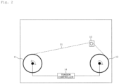
- Fig. 2 is a view illustrating the configuration of an optical fiber winding device according to the present embodiment.
- the optical fiber winding device includes:
- the optical fiber 51 is wound in advance around the feeding-out-side bobbin 11.
- the optical fiber 50 is an optical fiber to be tested
- the optical fiber 51 is an optical fiber for creating the same environment as in the optical cable.
- the optical fiber 51 is fed out from the feeding-out-side bobbin 11 and wound around the winding-side bobbin 12. Power for winding is applied to the shaft portion of the winding-side bobbin 12, and for example, an electric motor may be used.
- a function capable of applying tension to the optical fiber is imparted to the shaft of the feeding-out-side bobbin 11.
- This function is a brake or an electric motor.
- the tension can be applied to the optical fiber 51 by applying a brake to the rotation of the bobbin 11 or by making the number of rotations of the bobbin 11 slightly lower than the number of rotations of the bobbin 12 with an electric motor.
- the tension controller 14 can control the strength of the brake or the number of rotations of the electric motor to control the tension applied to the optical fiber 51.
- the optical fiber winding device of the present invention may further include a tension measuring portion 15 that measures a tension applied to the optical fiber 51 and feeds back the measured tension to the tension controller 14 so that the measured tension becomes the desired tension.
- the tension measuring portion 15 includes three pulleys (151, 152, and 153) and a measuring instrument 150, and the optical fiber 51 is disposed so as to meander on the three pulleys.
- a tension is applied to the optical fiber 51
- a force to push up the optical fiber 51 to the central pulley 152 is applied by a force to make the optical fiber 51 straight.
- the tension can be measured by measuring this force with the measuring instrument 150.
- the tension measuring portion 15 feeds back this tension to the tension controller 14, so that the desired tension can be kept constant.
- Fig. 4 is a view illustrating the structure of the positioning portion 13.
- the positioning portion 13 moves the optical fiber 51 in the axial direction of the bobbin 12 while the winding-side bobbin 12 rotates once, so that the optical fiber 51 can be wound around so as not to be lopsidedly inclined toward one place of the bobbin 12.
- the positioning portion 13 preferably sets a movement amount ⁇ in the axial direction of the bobbin 12 to be D ⁇ ⁇ ⁇ 2D each time the bobbin 12 rotates once.
- the outer diameter of the optical fiber 51 is referred to as D.
- the movement amount of the positioning portion 13 with respect to the axial direction of the bobbin 12 each time the bobbin 12 rotates once is referred to as ⁇ .
- ⁇ The movement amount of the positioning portion 13 with respect to the axial direction of the bobbin 12 each time the bobbin 12 rotates once.
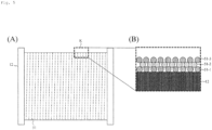
- Fig. 5 is a view illustrating the bobbin 12 with the optical fiber wound therearound.
- Fig. 5(A) is an overall view of the bobbin 12
- Fig. 5(B) is an enlarged cross-sectional view of portion K.
- Fig. 5(B) illustrates the same part as (Y) in Fig. 1(c) .
- the optical fiber 51-1 of the first layer is wound around the winding-side bobbin 12.
- the tension for winding the optical fiber 51-1 it is sufficient to apply the minimum tension to the extent of appropriately winding the optical fiber 51-1 around the bobbin 12.
- the tension is set to 10 to 100 gf.
- the tension can be increased from 10 to 100 gf in order to prevent the optical fiber 51-1 from being broken.
- the optical fiber 51-2 to be tested is wound around the second layer of the winding-side bobbin 12. It is desirable that the tension for winding the optical fiber 51-2 be as small as possible. This is because the lateral pressure applied to the optical fiber 51-2 is controlled by the tension of the optical fiber 51-3 of the third layer. Therefore, the tension when winding the optical fiber 51-2 is set to the minimum tension to the extent of appropriately winding the optical fiber around the bobbin 12. For example, the tension is set to 10 to 100 gf.
- the invariable characteristics of the optical fiber 51-2 may be confirmed by performing predetermined optical measurement on the optical fiber 51-2 before and after winding of the optical fiber of the second layer.
- the optical fiber 51-3 of the third layer is wound around the winding-side bobbin 12 with a desired tension.
- the optical fiber 51-2 is subjected to minute bending by the same lateral pressure as that in the high-density optical cable.
- the tension controller 14 applies a desired tension to the optical fiber 51-3 when the optical fiber 51-3 of the third layer is wound around the bobbin 12, which is stronger than the tension when the optical fibers (51-1 and 51-2) of the first layer and the second layer are wound around the bobbin 12.
- the optical fiber winding device further includes an optical measuring instrument (not illustrated) for performing optical measurement on the optical fiber 51-2 of the second layer.
- the optical measuring instrument is, for example, an optical time domain reflectometer (OTDR).
- OTD optical time domain reflectometer
- the optical measuring instrument is connected to the optical fiber 51-2 to be tested, and desired optical measurement (for example, propagation loss measurement) is performed.
- the lateral pressure applied to the optical fibers in the optical cable can be reproduced.
- the same lateral pressure as that in the optical cable can be applied to the optical fiber 51-2 for measurement.
- the optical fibers (51-1, 51-2, and 51-3) of each layer are three separated optical fibers, and these optical fibers are wound around the bobbin 12 has been described.
- the optical fibers (51-1, 51-2, and 51-3) of each layer may be one optical fiber.
- the three-layer optical fibers (51-1, 51-2, and 51-3) may be one continuous optical fiber (that is, only the section of the second layer is measured by the optical measuring instrument).
- the optical fiber 51 when the optical fiber 51 is wound around the bobbin 12, it is not necessary to cut the optical fiber and to exchange the feeding-out-side bobbin 11, and the test of an optical fiber can be simplified.
- Fig. 6 is a view illustrating the optical fiber testing method according to the present embodiment.
- the optical fiber testing method includes:
- the number of the optical fibers 51 may be one, and in the optical measurement, a section corresponding to the second layer of the optical fibers 51 may be measured, or the number of the optical fibers 51 may be three, and each of the optical fibers 51 may be wound on each layer.
- optical fiber testing method The following is a description of the optical fiber testing method according to the present embodiment.
- the present embodiment is an optical fiber testing method for applying lateral pressure to an optical fiber, and the method provides a test apparatus including:
- the optical fiber testing method includes, using the test apparatus: first, previously winding the optical fiber of the first layer around the winding-side bobbin;
- the test apparatus further includes: a tension measuring portion applied to the optical fiber; and a feedback portion that feeds back the measured tension to the control mechanism.
- the positioning portion sets a movement amount ⁇ in the axial direction of the bobbin to be D ⁇ ⁇ ⁇ 2D each time the bobbin rotates once, where D is an outer diameter of the optical fiber.
Landscapes
- Physics & Mathematics (AREA)
- Optics & Photonics (AREA)
- General Physics & Mathematics (AREA)
- Chemical & Material Sciences (AREA)
- Analytical Chemistry (AREA)
- Investigating Strength Of Materials By Application Of Mechanical Stress (AREA)
- Light Guides In General And Applications Therefor (AREA)
- Testing Of Optical Devices Or Fibers (AREA)
Abstract
Description
- The present disclosure relates to an optical fiber testing method for testing optical characteristics of an optical fiber, and an optical fiber winding device used in the testing.
- An optical fiber cable with a small diameter and high density by bundling optical fiber core wires has been proposed (see, for example, PTL 1). This optical fiber cable is formed by bundling optical fiber core wires at high density. Such a structure makes the fiber thinner and lighter, thereby improving handling properties and contributing to the construction of an economical optical fiber network. In realizing such an optical cable, it is necessary to design an optical fiber so as not to cause an increase in optical loss due to cabling.
- Generally, it is known that an optical fiber has an increased optical loss, which is caused by minute bending of the optical fiber, that is, microbend loss, when lateral pressure above a certain level is applied. Several methods of testing such microbend loss characteristics due to lateral pressure have been proposed. Of the testing methods,
Fig. 1(a) is a view illustrating a wire mesh method andFig. 1(b) is a view illustrating a sandpaper method. - The wire mesh method illustrated in
Fig. 1(a) is a method in which anoptical fiber 50 to be measured is wound on awire mesh 20 previously wound around acylindrical bobbin 10 to perform optical loss measurement. InFig. 1 , (X) is a view illustrating a cross section (a part of the surface of the bobbin in the cross section) intersected by a plane perpendicular to the axial direction of the bobbin, and (Y) is a view illustrating a cross section (a part of the surface of the bobbin in the cross section) intersected by a plane including the axis of the bobbin. - The sandpaper method illustrated in
Fig. 1(b) is a method in which theoptical fiber 50 to be measured is wound on asandpaper 30 previously wound around thecylindrical bobbin 10 to perform optical loss measurement. - Both of them are methods of pressing the
optical fiber 50 against thewire mesh 20 and thesandpaper 30 to give lateral pressure and minute bending, and testing the microbend loss characteristics (see, for example, NPL 1). -
- [PTL 1]
WO 2010/001663 - [NPL 1] "An Overview of Macrobending and Microbending of Optical Fibers," Internet URL https://www.corning.com/media/worldwide/coc/documents/Fiber/wh ite-paper/WP1212.pdf, retrieved on May 14, 2021
- However, in the technique of
NPL 1, the loss characteristics greatly differ depending on the wire diameter and mesh roughness of the wire mesh or the particle roughness and shape of the sandpaper. In the case of the wire mesh, the lateral pressure applied to the optical fiber acts only on the surface where the wire mesh and the optical fiber are in contact with each other so as to cross each other as illustrated inFig. 1(a) , and the condition is greatly different from the condition of the optical fiber in the optical cable. - Similarly, also in the case of the sandpaper, the lateral pressure acts on the optical fiber only on the surface where the unevenness of the sandpaper is irregularly in contact with the optical fiber as illustrated in
Fig. 1(b) , and the condition is greatly different from the condition of the optical fiber in the optical cable. - In other words, in the technique of
NPL 1, it is difficult to appropriately reproduce the same lateral pressure and minute bending state as those in the optical cable in the test of an optical fiber, and it is only possible to compare the relative characteristics of the optical fiber under the same test conditions. Therefore, the technique ofNPL 1 has a problem that it is difficult to design an optical fiber so as to suppress the loss of a high-density optical cable. - Therefore, in order to solve the above problem, an object of the present invention is to provide an optical fiber testing method and an optical fiber winding device capable of appropriately reproducing the same lateral pressure and minute bending state in a test of an optical fiber as those in an optical cable.
- In order to achieve the above-mentioned object, an optical fiber testing method and an optical fiber winding device according to the present invention have a function of bringing optical fibers into contact with each other and applying minute bending due to lateral pressure as in the case of a high-density optical cable.
- Specifically, an optical fiber testing method according to the present invention includes:
- winding three layers of optical fibers around a bobbin;
- applying a desired tension to the optical fiber when the optical fiber of the third layer is wound around the bobbin, which is stronger than a tension when the optical fibers of the first and second layers are wound around the bobbin; and
- performing optical measurement on the optical fiber of the second layer.
- Further, an optical fiber winding device according to the present invention includes: a bobbin for winding an optical fiber that is supplied; a positioning portion for winding the optical fiber at a desired position in an axial direction of the bobbin; and a tension controller that applies a desired tension to the optical fiber when the optical fiber is wound around the bobbin.
- The optical fiber winding device according to the present invention further includes a tension measuring portion that measures a tension applied to the optical fiber and feeds back the measured tension to the tension controller so that the measured tension becomes the desired tension.
- In the optical fiber winding device according to the present invention, the positioning portion sets a movement amount Δ in an axial direction of the bobbin to be D ≤ Δ < 2D each time the bobbin rotates once, where D is an outer diameter of the optical fiber.
- In the optical fiber winding device according to the present invention, the tension controller applies a desired tension to the optical fiber when the optical fiber of the third layer is wound around the bobbin, which is stronger than a tension when the optical fibers of the first and second layers are wound around the bobbin.
- The optical fiber winding device according to the present invention further includes an optical measuring instrument for performing optical measurement on the optical fiber of the second layer.
- In this optical fiber testing method, as illustrated in
Fig. 1(c) , an optical fiber 51-2 of the second layer wound around abobbin 12 is used as an object to be tested. Lateral pressure to the optical fiber 51-2 of the second layer is applied by an optical fiber 51-3 of the third layer. The lateral pressure is adjusted by a tension when the optical fiber 51-3 of the third layer is wound around the bobbin. In other words, since the lateral pressure is applied to the optical fiber to be tested from another optical fiber, the same lateral pressure and minute bending state as those in the optical cable can be reproduced. - Accordingly, the present invention can provide an optical fiber testing method and an optical fiber winding device capable of appropriately reproducing the same lateral pressure and minute bending state as those in the optical cable in the test of an optical fiber.
- In this optical fiber testing method, the number of the optical fibers may be one, and in the optical measurement, a section corresponding to the second layer of the optical fibers may be measured, or the number of the optical fibers may be three, and each of the three optical fibers may be wound on each layer.
- The above inventions can be combined whenever possible.
- The present invention can provide an optical fiber testing method and an optical fiber winding device capable of appropriately reproducing the same lateral pressure and minute bending state in the test of an optical fiber as those in the optical cable.
-
- [
Fig. 1 ]
Fig. 1 is a view illustrating a method of applying lateral pressure and minute bending to an optical fiber. - [
Fig. 2 ]
Fig. 2 is a view illustrating the structure of an optical fiber winding device according to the present invention. - [
Fig. 3 ]
Fig. 3 is a view illustrating the structure of the optical fiber winding device according to the present invention. - [
Fig. 4 ]
Fig. 4 is a view illustrating a positioning portion of the optical fiber winding device according to the present invention. - [
Fig. 5 ]
Fig. 5 is a view illustrating the state of an optical fiber wound by the optical fiber winding device according to the present invention. - [
Fig. 6 ]
Fig. 6 is a view illustrating an optical fiber testing method according to the present invention. - Embodiments of the present invention will be described with reference to the accompanying drawings. The embodiments described below are examples of the present invention, and the present invention is not limited to the following embodiments. Note that, in the present specification and the drawings, components having the same reference numerals indicate the same components.
-
Fig. 2 is a view illustrating the configuration of an optical fiber winding device according to the present embodiment. The optical fiber winding device includes: - a winding-
side bobbin 12 for winding anoptical fiber 51 supplied from a feeding-out-side bobbin 11; - a
positioning portion 13 for winding theoptical fiber 51 at a desired position in the axial direction of thebobbin 12; and - a
tension controller 14 that applies a desired tension to theoptical fiber 51 when theoptical fiber 51 is wound around thebobbin 12. - The
optical fiber 51 is wound in advance around the feeding-out-side bobbin 11. Here, theoptical fiber 50 is an optical fiber to be tested, and theoptical fiber 51 is an optical fiber for creating the same environment as in the optical cable. Theoptical fiber 51 is fed out from the feeding-out-side bobbin 11 and wound around the winding-side bobbin 12. Power for winding is applied to the shaft portion of the winding-side bobbin 12, and for example, an electric motor may be used. - A function capable of applying tension to the optical fiber is imparted to the shaft of the feeding-out-
side bobbin 11. This function is a brake or an electric motor. The tension can be applied to theoptical fiber 51 by applying a brake to the rotation of thebobbin 11 or by making the number of rotations of thebobbin 11 slightly lower than the number of rotations of thebobbin 12 with an electric motor. Thetension controller 14 can control the strength of the brake or the number of rotations of the electric motor to control the tension applied to theoptical fiber 51. - As illustrated in
Fig. 3 , the optical fiber winding device of the present invention may further include atension measuring portion 15 that measures a tension applied to theoptical fiber 51 and feeds back the measured tension to thetension controller 14 so that the measured tension becomes the desired tension. - As illustrated in
Fig. 3 , for example, thetension measuring portion 15 includes three pulleys (151, 152, and 153) and a measuringinstrument 150, and theoptical fiber 51 is disposed so as to meander on the three pulleys. When a tension is applied to theoptical fiber 51, a force to push up theoptical fiber 51 to thecentral pulley 152 is applied by a force to make theoptical fiber 51 straight. The tension can be measured by measuring this force with the measuringinstrument 150. Further, thetension measuring portion 15 feeds back this tension to thetension controller 14, so that the desired tension can be kept constant. -
Fig. 4 is a view illustrating the structure of thepositioning portion 13. The positioningportion 13 moves theoptical fiber 51 in the axial direction of thebobbin 12 while the winding-side bobbin 12 rotates once, so that theoptical fiber 51 can be wound around so as not to be lopsidedly inclined toward one place of thebobbin 12. For example, when the outer diameter of theoptical fiber 51 is referred to as D, the positioningportion 13 preferably sets a movement amount Δ in the axial direction of thebobbin 12 to be D ≤ Δ < 2D each time thebobbin 12 rotates once. - The outer diameter of the
optical fiber 51 is referred to as D. The movement amount of thepositioning portion 13 with respect to the axial direction of thebobbin 12 each time thebobbin 12 rotates once is referred to as Δ. By setting the movement amount Δ to D ≤ Δ, the adjacent optical fibers of each layer can be prevented from coming into contact with each other. Further, by setting the movement amount Δ to Δ < 2D, the optical fibers in the upper layer can be prevented from entering between the optical fibers in the lower layer. -
Fig. 5 is a view illustrating thebobbin 12 with the optical fiber wound therearound.Fig. 5(A) is an overall view of thebobbin 12, andFig. 5(B) is an enlarged cross-sectional view of portion K.Fig. 5(B) illustrates the same part as (Y) inFig. 1(c) . - First, the optical fiber 51-1 of the first layer is wound around the winding-
side bobbin 12. Here, as the tension for winding the optical fiber 51-1, it is sufficient to apply the minimum tension to the extent of appropriately winding the optical fiber 51-1 around thebobbin 12. For example, the tension is set to 10 to 100 gf. When the optical fibers (51-2 and 51-3) of the second layer and the third layer are wound from the outside of the optical fiber 51-1, the tension can be increased from 10 to 100 gf in order to prevent the optical fiber 51-1 from being broken. - Next, the optical fiber 51-2 to be tested is wound around the second layer of the winding-
side bobbin 12. It is desirable that the tension for winding the optical fiber 51-2 be as small as possible. This is because the lateral pressure applied to the optical fiber 51-2 is controlled by the tension of the optical fiber 51-3 of the third layer. Therefore, the tension when winding the optical fiber 51-2 is set to the minimum tension to the extent of appropriately winding the optical fiber around thebobbin 12. For example, the tension is set to 10 to 100 gf. - Here, as an option, for confirmation on whether the tension in winding the optical fiber 51-2 is appropriate or not, the invariable characteristics of the optical fiber 51-2 may be confirmed by performing predetermined optical measurement on the optical fiber 51-2 before and after winding of the optical fiber of the second layer.
- Subsequently, the optical fiber 51-3 of the third layer is wound around the winding-
side bobbin 12 with a desired tension. With this tension, the optical fiber 51-2 is subjected to minute bending by the same lateral pressure as that in the high-density optical cable. Specifically, thetension controller 14 applies a desired tension to the optical fiber 51-3 when the optical fiber 51-3 of the third layer is wound around thebobbin 12, which is stronger than the tension when the optical fibers (51-1 and 51-2) of the first layer and the second layer are wound around thebobbin 12. - The optical fiber winding device further includes an optical measuring instrument (not illustrated) for performing optical measurement on the optical fiber 51-2 of the second layer. The optical measuring instrument is, for example, an optical time domain reflectometer (OTDR). The optical measuring instrument is connected to the optical fiber 51-2 to be tested, and desired optical measurement (for example, propagation loss measurement) is performed.
- By setting the
optical fibers 51 of each layer in the same kind, the lateral pressure applied to the optical fibers in the optical cable can be reproduced. By such a method, the same lateral pressure as that in the optical cable can be applied to the optical fiber 51-2 for measurement. - In the above embodiment, an example in which the optical fibers (51-1, 51-2, and 51-3) of each layer are three separated optical fibers, and these optical fibers are wound around the
bobbin 12 has been described. As another embodiment, the optical fibers (51-1, 51-2, and 51-3) of each layer may be one optical fiber. When measurement is performed by an optical measuring instrument such as an OTDR capable of measuring distribution in the longitudinal direction of the optical fiber, the three-layer optical fibers (51-1, 51-2, and 51-3) may be one continuous optical fiber (that is, only the section of the second layer is measured by the optical measuring instrument). In the case of this embodiment, when theoptical fiber 51 is wound around thebobbin 12, it is not necessary to cut the optical fiber and to exchange the feeding-out-side bobbin 11, and the test of an optical fiber can be simplified. -
Fig. 6 is a view illustrating the optical fiber testing method according to the present embodiment. The optical fiber testing method includes: - winding three layers of the
optical fibers 51 around the bobbin 12 (step S01); - applying a desired tension to the optical fiber 51-3 when the optical fiber 51-3 of the third layer is wound around the
bobbin 12, which is stronger than a tension when the optical fibers (51-1 and 51-2) of the first and second layers are wound around thebobbin 12; and - performing optical measurement on the optical fiber 51-2 of the second layer (step S02).
- In the optical fiber testing method, the number of the
optical fibers 51 may be one, and in the optical measurement, a section corresponding to the second layer of theoptical fibers 51 may be measured, or the number of theoptical fibers 51 may be three, and each of theoptical fibers 51 may be wound on each layer. - The following is a description of the optical fiber testing method according to the present embodiment.
- The present embodiment is an optical fiber testing method for applying lateral pressure to an optical fiber, and the method provides a test apparatus including:
- a feeding-out-side bobbin for feeding out an optical fiber;
- a winding-side bobbin for winding the optical fiber;
- a feeding-out portion that fixes the feeding-out-side bobbin; a winding portion that fixes the winding-side bobbin;
- power that applies rotation to the bobbin to wind the optical fiber in the winding portion;
- a control mechanism for controlling the rotation applied to the bobbin by braking or changing the number of rotations in feeding out the optical fiber from the feeding-out portion; and
- a positioning portion for winding the optical fiber at a desired position in the axial direction of the winding-side bobbin,
- in which, in winding the optical fiber, previously wound around the feeding-out-side bobbin, around the winding-side bobbin, the optical fiber is wound with a tension, applied to the optical fiber, maintained by the control mechanism.
- The optical fiber testing method includes, using the test apparatus: first, previously winding the optical fiber of the first layer around the winding-side bobbin;
- second, winding an optical fiber to be tested, which has been previously wound around the feeding-out-side bobbin, around the second layer of the winding-side bobbin;
- third, winding the optical fiber of the third layer around the winding-side bobbin in a state in which a tension is applied; and
- fourth, performing optical measurement on the optical fiber to be tested.
- The test apparatus further includes: a tension measuring portion applied to the optical fiber; and a feedback portion that feeds back the measured tension to the control mechanism.
- The positioning portion sets a movement amount Δ in the axial direction of the bobbin to be D ≤ Δ < 2D each time the bobbin rotates once, where D is an outer diameter of the optical fiber.
- By using the present invention, it is possible to reproduce lateral pressure and minute bending in a high-density optical cable, and to test characteristics of microbend loss of an optical fiber necessary for making the loss characteristics of the optical cable appropriate.
-
- 11: Feeding-out-side bobbin
- 12: Winding-side bobbin
- 13: Positioning portion
- 14: Tension controller
- 15: Tension measuring portion
- 20: Wire mesh
- 30: Sandpaper
- 51: Optical fiber
- 51-1: Optical fiber of first layer
- 51-2: Optical fiber of second layer
- 51-3: Optical fiber of third layer
- 150: Measuring instrument
- 151 to 153: Pulley
Claims (8)
- An optical fiber testing method comprising:winding three layers of optical fibers around a bobbin;applying a desired tension to the optical fiber when the optical fiber of the third layer is wound around the bobbin, which is stronger than a tension when the optical fibers of the first and second layers are wound around the bobbin; andperforming optical measurement on the optical fiber of the second layer.
- The optical fiber testing method according to claim 1,wherein the number of the optical fibers is one, andin the optical measurement, a section corresponding to the second layer of the optical fibers is measured.
- The optical fiber testing method according to claim 1, wherein the number of the optical fibers is three, and each of the optical fibers is wound on each layer.
- An optical fiber winding device comprising:a bobbin for winding an optical fiber that is supplied;a positioning portion for winding the optical fiber at a desired position in an axial direction of the bobbin; anda tension controller that applies a desired tension to the optical fiber when the optical fiber is wound around the bobbin.
- The optical fiber winding device according to claim 4, further comprising a tension measuring portion that measures a tension applied to the optical fiber and feeds back the measured tension to the tension controller so that the measured tension becomes the desired tension.
- The optical fiber winding device according to claim 4 or 5, wherein the positioning portion sets
a movement amount Δ in an axial direction of the bobbin to be D ≤ Δ < 2D each time the bobbin rotates once, where D is an outer diameter of the optical fiber. - The optical fiber winding device according to any one of claims 4 to 6, wherein the tension controller applies a desired tension to the optical fiber when the optical fiber of the third layer is wound around the bobbin, which is stronger than a tension when the optical fibers of the first and second layers are wound around the bobbin.
- The optical fiber winding device according to claim 7, further comprising an optical measuring instrument for performing optical measurement on the optical fiber of the second layer.
Applications Claiming Priority (1)
| Application Number | Priority Date | Filing Date | Title |
|---|---|---|---|
| PCT/JP2021/020754 WO2022254557A1 (en) | 2021-05-31 | 2021-05-31 | Optical fiber test method and optical fiber winding device |
Publications (2)
| Publication Number | Publication Date |
|---|---|
| EP4350316A1 true EP4350316A1 (en) | 2024-04-10 |
| EP4350316A4 EP4350316A4 (en) | 2025-03-12 |
Family
ID=84323999
Family Applications (1)
| Application Number | Title | Priority Date | Filing Date |
|---|---|---|---|
| EP21944065.8A Pending EP4350316A4 (en) | 2021-05-31 | 2021-05-31 | Optical fiber test method and optical fiber winding device |
Country Status (5)
| Country | Link |
|---|---|
| US (1) | US12590866B2 (en) |
| EP (1) | EP4350316A4 (en) |
| JP (1) | JP7563594B2 (en) |
| CN (1) | CN117441095A (en) |
| WO (1) | WO2022254557A1 (en) |
Family Cites Families (18)
| Publication number | Priority date | Publication date | Assignee | Title |
|---|---|---|---|---|
| JPS59198337A (en) * | 1983-04-27 | 1984-11-10 | Nippon Telegr & Teleph Corp <Ntt> | Inspection of optical fiber |
| DE3643525A1 (en) * | 1986-12-19 | 1988-06-30 | Philips Patentverwaltung | METHOD AND DEVICE FOR MEASURING THE ADDITIONAL DAMPING RESULTING FROM CURVES IN A FOC |
| JPH0659139A (en) * | 1992-08-10 | 1994-03-04 | Fujikura Ltd | Method and instrument for measuring transmission loss of optical fiber |
| JPH06288865A (en) * | 1993-04-02 | 1994-10-18 | Showa Electric Wire & Cable Co Ltd | Measuring apparatus for loss of optical fiber |
| JP2784155B2 (en) | 1995-02-07 | 1998-08-06 | 川崎重工業株式会社 | Optical fiber high speed feeding test equipment |
| KR20030015377A (en) * | 2000-07-11 | 2003-02-20 | 코닝 인코포레이티드 | Variable tension fiber winding |
| DE10033541C2 (en) * | 2000-07-11 | 2003-05-15 | Litef Gmbh | Optical fiber coil for a fiber optic Sagnac interferometer and method for its production |
| JP2002310850A (en) * | 2001-04-16 | 2002-10-23 | Sumitomo Electric Ind Ltd | Jig for measuring bending loss of optical fiber and bending loss measuring method |
| KR100549348B1 (en) * | 2003-07-11 | 2006-02-03 | 삼성전자주식회사 | Automatic control device for winding optical fiber and control method using same |
| KR100624247B1 (en) * | 2004-07-02 | 2006-09-19 | 엘에스전선 주식회사 | Multimode Fiber Optics for High Speed LAN |
| CN102057309B (en) | 2008-06-30 | 2014-04-16 | 日本电信电话株式会社 | Fiber optic cables and ribbons |
| JP2012018134A (en) * | 2010-07-09 | 2012-01-26 | Sumitomo Electric Ind Ltd | Bend loss measuring device for optical fibers |
| JP5512462B2 (en) * | 2010-08-20 | 2014-06-04 | 株式会社フジクラ | Method for measuring longitudinal distribution of bending loss of optical fiber and optical fiber line, optical line test method, and optical fiber manufacturing method |
| EP3431451B1 (en) | 2016-03-18 | 2021-04-28 | Furukawa Electric Co., Ltd. | Optical fiber screening device and optical fiber screening method |
| GB2582345B (en) * | 2019-03-20 | 2023-06-28 | Safran Electrical & Power | Improved method for manufacturing a rotor |
| CN210665360U (en) * | 2019-06-06 | 2020-06-02 | 天津市金盛源特种建材有限公司 | Detection apparatus for mix fibre inflation anticracking agent's concrete sulfate erosion resistance ability |
| CN114174206B (en) * | 2019-09-30 | 2024-02-02 | 株式会社藤仓 | Optical fiber extraction device, optical fiber extraction method, and optical fiber inspection method |
| CN111829754A (en) | 2020-08-31 | 2020-10-27 | 成都泰瑞通信设备检测有限公司 | Optical fiber microbend test device, test system and test method for slotting on outer surface of metal cylinder |
-
2021
- 2021-05-31 JP JP2023525198A patent/JP7563594B2/en active Active
- 2021-05-31 US US18/289,233 patent/US12590866B2/en active Active
- 2021-05-31 WO PCT/JP2021/020754 patent/WO2022254557A1/en not_active Ceased
- 2021-05-31 EP EP21944065.8A patent/EP4350316A4/en active Pending
- 2021-05-31 CN CN202180098249.9A patent/CN117441095A/en active Pending
Also Published As
| Publication number | Publication date |
|---|---|
| WO2022254557A1 (en) | 2022-12-08 |
| US12590866B2 (en) | 2026-03-31 |
| US20240248001A1 (en) | 2024-07-25 |
| CN117441095A (en) | 2024-01-23 |
| JP7563594B2 (en) | 2024-10-08 |
| JPWO2022254557A1 (en) | 2022-12-08 |
| EP4350316A4 (en) | 2025-03-12 |
Similar Documents
| Publication | Publication Date | Title |
|---|---|---|
| US8548294B2 (en) | Optical fiber cable and optical fiber ribbon | |
| US6898355B2 (en) | Functionally strained optical fibers | |
| KR101120703B1 (en) | Rope | |
| EP0393878A2 (en) | Helical bend proof testing of optical fibers | |
| JP5879453B1 (en) | Method of introducing initial tensile strain into cable and optical fiber | |
| EP3521883A1 (en) | Optical fiber colored core, optical fiber cable, and method for manufacturing optical fiber colored core | |
| KR100899515B1 (en) | Optical fiber coil and manufacturing method of the same | |
| CN109477295B (en) | Steel cable | |
| US12590866B2 (en) | Optical fiber test method and wrapping optical fiber device | |
| CN111480063B (en) | Optical fiber core wire screening method and device, and optical fiber core wire manufacturing method | |
| JP2784155B2 (en) | Optical fiber high speed feeding test equipment | |
| EP3502759B1 (en) | Device and method for inspecting optical fiber unit | |
| RU196039U1 (en) | Geophysical Fiber Optic Stabilized Cable | |
| JP2007183477A (en) | Fiber optic cable | |
| JP2021189231A (en) | Coated optical fiber, optical fiber ribbon, and optical fiber cable | |
| JP7847461B2 (en) | Method for screening and manufacturing optical fiber strands | |
| JP2008083696A (en) | Optical fiber coil and manufacturing method thereof | |
| JPH07225330A (en) | Optical complex optical unit for overhead ground wire | |
| JPH09197209A (en) | Optical fiber ribbon | |
| JP7613003B2 (en) | Optical fiber assemblage manufacturing method and manufacturing device | |
| JP2014125405A (en) | Optical fiber strand | |
| JP4927684B2 (en) | Optical fiber strands, optical fiber tape cores and optical cables suitable for small diameter multi-core cables | |
| JP2670377B2 (en) | Connection method of multi-core optical fiber with same diameter | |
| CN117769638A (en) | PC steel strand with optical fiber, strain measuring device and manufacturing method of PC steel strand with optical fiber | |
| US20030021559A1 (en) | Functionally tensioned optical fibers to form ribbons with controlled geometry, optimized residual strain and reduced attenuation |
Legal Events
| Date | Code | Title | Description |
|---|---|---|---|
| STAA | Information on the status of an ep patent application or granted ep patent |
Free format text: STATUS: THE INTERNATIONAL PUBLICATION HAS BEEN MADE |
|
| PUAI | Public reference made under article 153(3) epc to a published international application that has entered the european phase |
Free format text: ORIGINAL CODE: 0009012 |
|
| STAA | Information on the status of an ep patent application or granted ep patent |
Free format text: STATUS: REQUEST FOR EXAMINATION WAS MADE |
|
| 17P | Request for examination filed |
Effective date: 20240102 |
|
| AK | Designated contracting states |
Kind code of ref document: A1 Designated state(s): AL AT BE BG CH CY CZ DE DK EE ES FI FR GB GR HR HU IE IS IT LI LT LU LV MC MK MT NL NO PL PT RO RS SE SI SK SM TR |
|
| DAV | Request for validation of the european patent (deleted) | ||
| DAX | Request for extension of the european patent (deleted) | ||
| A4 | Supplementary search report drawn up and despatched |
Effective date: 20250206 |
|
| RIC1 | Information provided on ipc code assigned before grant |
Ipc: G02B 6/00 20060101ALI20250131BHEP Ipc: G01M 11/02 20060101AFI20250131BHEP |
|
| RAP3 | Party data changed (applicant data changed or rights of an application transferred) |
Owner name: NTT, INC. |
|
| STAA | Information on the status of an ep patent application or granted ep patent |
Free format text: STATUS: EXAMINATION IS IN PROGRESS |
|
| GRAP | Despatch of communication of intention to grant a patent |
Free format text: ORIGINAL CODE: EPIDOSNIGR1 |
|
| STAA | Information on the status of an ep patent application or granted ep patent |
Free format text: STATUS: GRANT OF PATENT IS INTENDED |
|
| 17Q | First examination report despatched |
Effective date: 20251127 |
|
| INTG | Intention to grant announced |
Effective date: 20251217 |
|
| GRAS | Grant fee paid |
Free format text: ORIGINAL CODE: EPIDOSNIGR3 |
|
| GRAA | (expected) grant |
Free format text: ORIGINAL CODE: 0009210 |
|
| STAA | Information on the status of an ep patent application or granted ep patent |
Free format text: STATUS: THE PATENT HAS BEEN GRANTED |