EP4350268A1 - Tube-in-tube unified shell heat exchanger - Google Patents
Tube-in-tube unified shell heat exchanger Download PDFInfo
- Publication number
- EP4350268A1 EP4350268A1 EP23201569.3A EP23201569A EP4350268A1 EP 4350268 A1 EP4350268 A1 EP 4350268A1 EP 23201569 A EP23201569 A EP 23201569A EP 4350268 A1 EP4350268 A1 EP 4350268A1
- Authority
- EP
- European Patent Office
- Prior art keywords
- tube structure
- tube
- inner tube
- heat exchanger
- outer tube
- Prior art date
- Legal status (The legal status is an assumption and is not a legal conclusion. Google has not performed a legal analysis and makes no representation as to the accuracy of the status listed.)
- Granted
Links
Images






Classifications
-
- F—MECHANICAL ENGINEERING; LIGHTING; HEATING; WEAPONS; BLASTING
- F28—HEAT EXCHANGE IN GENERAL
- F28D—HEAT-EXCHANGE APPARATUS, NOT PROVIDED FOR IN ANOTHER SUBCLASS, IN WHICH THE HEAT-EXCHANGE MEDIA DO NOT COME INTO DIRECT CONTACT
- F28D7/00—Heat-exchange apparatus having stationary tubular conduit assemblies for both heat-exchange media, the media being in contact with different sides of a conduit wall
- F28D7/10—Heat-exchange apparatus having stationary tubular conduit assemblies for both heat-exchange media, the media being in contact with different sides of a conduit wall the conduits being arranged one within the other, e.g. concentrically
- F28D7/12—Heat-exchange apparatus having stationary tubular conduit assemblies for both heat-exchange media, the media being in contact with different sides of a conduit wall the conduits being arranged one within the other, e.g. concentrically the surrounding tube being closed at one end, e.g. return type
-
- F—MECHANICAL ENGINEERING; LIGHTING; HEATING; WEAPONS; BLASTING
- F28—HEAT EXCHANGE IN GENERAL
- F28D—HEAT-EXCHANGE APPARATUS, NOT PROVIDED FOR IN ANOTHER SUBCLASS, IN WHICH THE HEAT-EXCHANGE MEDIA DO NOT COME INTO DIRECT CONTACT
- F28D21/00—Heat-exchange apparatus not covered by any of the groups F28D1/00 - F28D20/00
- F28D21/0001—Recuperative heat exchangers
- F28D21/0003—Recuperative heat exchangers the heat being recuperated from exhaust gases
-
- F—MECHANICAL ENGINEERING; LIGHTING; HEATING; WEAPONS; BLASTING
- F28—HEAT EXCHANGE IN GENERAL
- F28F—DETAILS OF HEAT-EXCHANGE AND HEAT-TRANSFER APPARATUS, OF GENERAL APPLICATION
- F28F1/00—Tubular elements; Assemblies of tubular elements
- F28F1/10—Tubular elements and assemblies thereof with means for increasing heat-transfer area, e.g. with fins, with projections, with recesses
- F28F1/12—Tubular elements and assemblies thereof with means for increasing heat-transfer area, e.g. with fins, with projections, with recesses the means being only outside the tubular element
- F28F1/124—Tubular elements and assemblies thereof with means for increasing heat-transfer area, e.g. with fins, with projections, with recesses the means being only outside the tubular element and being formed of pins
-
- F—MECHANICAL ENGINEERING; LIGHTING; HEATING; WEAPONS; BLASTING
- F28—HEAT EXCHANGE IN GENERAL
- F28F—DETAILS OF HEAT-EXCHANGE AND HEAT-TRANSFER APPARATUS, OF GENERAL APPLICATION
- F28F1/00—Tubular elements; Assemblies of tubular elements
- F28F1/10—Tubular elements and assemblies thereof with means for increasing heat-transfer area, e.g. with fins, with projections, with recesses
- F28F1/12—Tubular elements and assemblies thereof with means for increasing heat-transfer area, e.g. with fins, with projections, with recesses the means being only outside the tubular element
- F28F1/34—Tubular elements and assemblies thereof with means for increasing heat-transfer area, e.g. with fins, with projections, with recesses the means being only outside the tubular element and extending obliquely
- F28F1/36—Tubular elements and assemblies thereof with means for increasing heat-transfer area, e.g. with fins, with projections, with recesses the means being only outside the tubular element and extending obliquely the means being helically wound fins or wire spirals
-
- F—MECHANICAL ENGINEERING; LIGHTING; HEATING; WEAPONS; BLASTING
- F28—HEAT EXCHANGE IN GENERAL
- F28F—DETAILS OF HEAT-EXCHANGE AND HEAT-TRANSFER APPARATUS, OF GENERAL APPLICATION
- F28F1/00—Tubular elements; Assemblies of tubular elements
- F28F1/10—Tubular elements and assemblies thereof with means for increasing heat-transfer area, e.g. with fins, with projections, with recesses
- F28F1/40—Tubular elements and assemblies thereof with means for increasing heat-transfer area, e.g. with fins, with projections, with recesses the means being only inside the tubular element
-
- F—MECHANICAL ENGINEERING; LIGHTING; HEATING; WEAPONS; BLASTING
- F28—HEAT EXCHANGE IN GENERAL
- F28F—DETAILS OF HEAT-EXCHANGE AND HEAT-TRANSFER APPARATUS, OF GENERAL APPLICATION
- F28F1/00—Tubular elements; Assemblies of tubular elements
- F28F1/10—Tubular elements and assemblies thereof with means for increasing heat-transfer area, e.g. with fins, with projections, with recesses
- F28F1/42—Tubular elements and assemblies thereof with means for increasing heat-transfer area, e.g. with fins, with projections, with recesses the means being both outside and inside the tubular element
- F28F1/422—Tubular elements and assemblies thereof with means for increasing heat-transfer area, e.g. with fins, with projections, with recesses the means being both outside and inside the tubular element with outside means integral with the tubular element and inside means integral with the tubular element
-
- F—MECHANICAL ENGINEERING; LIGHTING; HEATING; WEAPONS; BLASTING
- F28—HEAT EXCHANGE IN GENERAL
- F28D—HEAT-EXCHANGE APPARATUS, NOT PROVIDED FOR IN ANOTHER SUBCLASS, IN WHICH THE HEAT-EXCHANGE MEDIA DO NOT COME INTO DIRECT CONTACT
- F28D21/00—Heat-exchange apparatus not covered by any of the groups F28D1/00 - F28D20/00
- F28D2021/0019—Other heat exchangers for particular applications; Heat exchange systems not otherwise provided for
- F28D2021/0026—Other heat exchangers for particular applications; Heat exchange systems not otherwise provided for for combustion engines, e.g. for gas turbines or for Stirling engines
-
- F—MECHANICAL ENGINEERING; LIGHTING; HEATING; WEAPONS; BLASTING
- F28—HEAT EXCHANGE IN GENERAL
- F28D—HEAT-EXCHANGE APPARATUS, NOT PROVIDED FOR IN ANOTHER SUBCLASS, IN WHICH THE HEAT-EXCHANGE MEDIA DO NOT COME INTO DIRECT CONTACT
- F28D7/00—Heat-exchange apparatus having stationary tubular conduit assemblies for both heat-exchange media, the media being in contact with different sides of a conduit wall
- F28D7/16—Heat-exchange apparatus having stationary tubular conduit assemblies for both heat-exchange media, the media being in contact with different sides of a conduit wall the conduits being arranged in parallel spaced relation
- F28D7/1607—Heat-exchange apparatus having stationary tubular conduit assemblies for both heat-exchange media, the media being in contact with different sides of a conduit wall the conduits being arranged in parallel spaced relation with particular pattern of flow of the heat exchange media, e.g. change of flow direction
-
- F—MECHANICAL ENGINEERING; LIGHTING; HEATING; WEAPONS; BLASTING
- F28—HEAT EXCHANGE IN GENERAL
- F28D—HEAT-EXCHANGE APPARATUS, NOT PROVIDED FOR IN ANOTHER SUBCLASS, IN WHICH THE HEAT-EXCHANGE MEDIA DO NOT COME INTO DIRECT CONTACT
- F28D7/00—Heat-exchange apparatus having stationary tubular conduit assemblies for both heat-exchange media, the media being in contact with different sides of a conduit wall
- F28D7/16—Heat-exchange apparatus having stationary tubular conduit assemblies for both heat-exchange media, the media being in contact with different sides of a conduit wall the conduits being arranged in parallel spaced relation
- F28D7/1615—Heat-exchange apparatus having stationary tubular conduit assemblies for both heat-exchange media, the media being in contact with different sides of a conduit wall the conduits being arranged in parallel spaced relation the conduits being inside a casing and extending at an angle to the longitudinal axis of the casing; the conduits crossing the conduit for the other heat exchange medium
-
- F—MECHANICAL ENGINEERING; LIGHTING; HEATING; WEAPONS; BLASTING
- F28—HEAT EXCHANGE IN GENERAL
- F28D—HEAT-EXCHANGE APPARATUS, NOT PROVIDED FOR IN ANOTHER SUBCLASS, IN WHICH THE HEAT-EXCHANGE MEDIA DO NOT COME INTO DIRECT CONTACT
- F28D7/00—Heat-exchange apparatus having stationary tubular conduit assemblies for both heat-exchange media, the media being in contact with different sides of a conduit wall
- F28D7/16—Heat-exchange apparatus having stationary tubular conduit assemblies for both heat-exchange media, the media being in contact with different sides of a conduit wall the conduits being arranged in parallel spaced relation
- F28D7/163—Heat-exchange apparatus having stationary tubular conduit assemblies for both heat-exchange media, the media being in contact with different sides of a conduit wall the conduits being arranged in parallel spaced relation with conduit assemblies having a particular shape, e.g. square or annular; with assemblies of conduits having different geometrical features; with multiple groups of conduits connected in series or parallel and arranged inside common casing
- F28D7/1669—Heat-exchange apparatus having stationary tubular conduit assemblies for both heat-exchange media, the media being in contact with different sides of a conduit wall the conduits being arranged in parallel spaced relation with conduit assemblies having a particular shape, e.g. square or annular; with assemblies of conduits having different geometrical features; with multiple groups of conduits connected in series or parallel and arranged inside common casing the conduit assemblies having an annular shape; the conduits being assembled around a central distribution tube
Definitions
- the present disclosure is directed to tube-in-tube heat exchanger, particularly tube-in-tube unified shell heat exchanger.
- Waste heat recovery heat exchangers are annular shaped, tube-style heat exchangers, situated aft of the turbine exit frame. Ideally, the operating fluid enters and exits from the outside diameter of that annulus, due to space constraints.
- the tubes are long and thin, but need to be rigid. Tubes must be allowed to thermally expand yet be constrained from excessive vibration.
- a tube-in-tube unified shell element heat exchanger comprising an outer tube structure comprising a tube wall defining a first end opposite a second end; the outer tube structure comprises an interior surface and an exterior surface opposite the interior surface; the interior surface includes an augmentation structure; the outer tube structure comprises an end cap connected to the second end of the tube wall; the outer tube structure comprises a top section proximate the first end; the top section includes a flange and a flow outlet; the tube wall of the outer tube structure connects with the top section proximate the flange to form an integral outer tube structure; an inner tube structure including a tubular shaped inner body defining an internal flow area, the inner tube structure including surface features formed on the exterior of the inner tube structure; the inner tube structure including a top ring connected to the exterior proximate an inlet port of the inner tube structure; inner tube structure includes an outlet port opposite the inlet port; wherein the top ring of the inner tube structure is connected with the top section of the outer tube structure
- a further embodiment of any of the foregoing embodiments may additionally and/or alternatively include the surface features comprise external flutes that spiral along a portion of the length of the inner tube structure.
- a further embodiment of any of the foregoing embodiments may additionally and/or alternatively include the augmentation structure along with the surface features are configured to provide vortex boundary mixing for an internal working fluid flowing between the exterior of the inner tube structure and interior surface of the outer tube structure.
- a further embodiment of any of the foregoing embodiments may additionally and/or alternatively include the gap is configured for each of the inner tube structure and the outer tube structure to independently expand/contract responsive to thermal gradients.
- a further embodiment of any of the foregoing embodiments may additionally and/or alternatively include the tube-in-tube unified shell element heat exchanger further comprising micro-fin surface features formed on the exterior surface of the outer tube structure.
- a further embodiment of any of the foregoing embodiments may additionally and/or alternatively include the surface features comprise spiraling external flutes having a spiral with a relative angle alpha to a longitudinal axis AA of the inner tube structure being from zero degrees to 30 degrees.
- An annular duct with tube-in-tube unified shell heat exchanger comprising the annular duct defined between an outer case and an inner case about an axis A; multiple tube-in-tube unified shell elements mounted to the outer case and extending into the annular duct radially relative to the axis A; each of the multiple tube-in-tube unified shell elements comprising an outer tube structure comprising a tube wall defining a first end opposite a second end; the outer tube structure comprises an interior surface and an exterior surface opposite the interior surface; the interior surface includes an augmentation structure; the outer tube structure; the outer tube structure comprises an end cap connected to the second end of the tube wall; the outer tube structure comprises a top section proximate the first end; the top section includes a flange and a flow outlet; the tube wall of the outer tube structure connects with the top section proximate the flange to form an integral outer tube structure; an inner tube structure including a tubular shaped inner body defining an internal flow area, the
- a further embodiment of any of the foregoing embodiments may additionally and/or alternatively include the augmentation structure comprises helical shaped fins extending along the interior surface.
- a further embodiment of any of the foregoing embodiments may additionally and/or alternatively include the surface features comprise external flutes that spiral along a portion of the length of the inner tube structure.
- a further embodiment of any of the foregoing embodiments may additionally and/or alternatively include the augmentation structure along with the surface features are configured to provide vortex boundary mixing for an internal working fluid flowing between the exterior of the inner tube structure and interior surface of the outer tube structure.
- a further embodiment of any of the foregoing embodiments may additionally and/or alternatively include the gap is configured for each of the inner tube structure and the outer tube structure to independently expand/contract responsive to thermal gradients.
- a further embodiment of any of the foregoing embodiments may additionally and/or alternatively include the annular duct with tube-in-tube unified shell heat exchanger further comprising micro-fin surface features formed on the exterior surface of the outer tube structure.
- a process for heat exchange through an annular duct with tube-in-tube unified shell element heat exchanger comprising flowing air through the annular duct defined between an outer case and an inner case about an axis A; mounting multiple tube-in-tube unified shell elements to the outer case extending into the annular duct radially relative to the axis A; each of the multiple tube-in-tube unified shell elements comprising an outer tube structure comprising a tube wall defining a first end opposite a second end; the outer tube structure comprises an interior surface and an exterior surface opposite the interior surface; the interior surface includes an augmentation structure; the outer tube structure; the outer tube structure comprises an end cap connected to the second end of the tube wall; the outer tube structure comprises a top section proximate the first end; the top section includes a flange and a flow outlet; the tube wall of the outer tube structure connects with the top section proximate the flange to form an integral outer tube structure; an inner tube structure including a tubular shaped
- a further embodiment of any of the foregoing embodiments may additionally and/or alternatively include the process further comprising mounting the flange flush with an outer surface of the outer case.
- a further embodiment of any of the foregoing embodiments may additionally and/or alternatively include the process further comprising forming vortex boundary mixing for the working fluid flowing through the gap past the augmentation structure and the surface features.
- a further embodiment of any of the foregoing embodiments may additionally and/or alternatively include the process further comprising setting the end cap within an inner surface receiver of the inner case; and forming a gap between the cap and the inner surface receiver.
- a further embodiment of any of the foregoing embodiments may additionally and/or alternatively include the process further comprising supplying and returning the working fluid from an exterior of the outer case.
- a further embodiment of any of the foregoing embodiments may additionally and/or alternatively include the working fluid is at pressures ranging from about 1 pound per square inch to about 5000 pounds per square inch
- a further embodiment of any of the foregoing embodiments may additionally and/or alternatively includethe working fluid is selected from the group consisting of a liquid or a supercritical fluid, air, liquid or super critical phase ammonia, liquid or super critical phase hydrogen, super critical phase carbon dioxide, and the like.
- the heat exchanger 10 can be a tube-in-tube unified shell (TITUS) heat exchanger 10.
- the heat exchanger 10 can be installed from an exterior of an annular duct 12.
- the annular duct 12 can be defined between an outer case 14 enveloping an inner case 16 about an axis A.
- the heat exchanger 10 can include multiple small diameter tubes 18 assembled as tube-in-tube elements 20.
- the small diameter tubes 18 can have an outside diameter of less than 0.100 inches.
- An internal working fluid 22 that flows through the tube-in-tube elements 20 can include a liquid or a supercritical fluid, such as for example, air (gas), ammonia (liquid/super critical), hydrogen (liquid/super critical), carbon dioxide (super critical), and the like.
- An external working fluid 23, such as air can be flowing exterior of the tube elements 20, for example in an air duct of a gas turbine engine.
- the internal working fluid 22 can be at high pressure, for example ranging from about 1 pound per square inch to about 5000 pounds per square inch.
- the tube elements 20 can be inserted from the exterior of the outer case 14 through the outer case 14 into the annular duct 12.
- This design allows for a heat exchanger 10 with an orientation and plumbing of the internal working fluid 22 to be supplied and returned from one side of the outer case 14, such as the exterior of the annular duct 12.
- the internal working fluid 22 can be supplied and returned from exterior of the outer case 14.
- the tube-in-tube unified shell elements or simply TITUS elements 20 include an inner tube structure 24 disposed within an outer tube structure 26.
- the inner tube structure 24 includes a tubular shaped inner body 28 having an internal flow area 30.
- the internal flow area 30 can be defined by a smooth bore 32 inside diameter of the inner tube structure 24, as seen in Figs. 5 and 7 .
- the inner tube structure 24 includes surface features 34 disposed and/or formed on the exterior/outer diameter 38 of the inner tube structure 24.
- the surface features 34 can be formed as external flutes or guide fins 34 that spiral along a portion of the length L of the inner tube structure 24 exposed to the working fluid.
- the inner tube structure 24 can be formed from thick walled tube stock.
- the surface features 34 can be machined into shape, such as the spiraling external flutes 34.
- a flow passage 39 can be defined between any two adjacent flutes 34.
- the height of flow passage 39, H (OD-ID)/2 of the annulus defined as the space between the outer tube structure 26 and inner tube structure 24, specifically, the inside diameter of the outer tube structure 26 shown at the interior surface 48 to the outside diameter 38 of the inner tube structure 24.
- the relative angle alpha (a) of the spiral S to the longitudinal axis AA of the inner tube structure 24 can be from about between 0 degrees (straight) and 30 degrees (see Fig. 9 ).
- the surface features 34 are configured to provide the flow passage 39 for the internal working fluid 22 flowing along the exterior of the inner tube structure 24.
- the inner tube structure 24 includes a top ring 40 shaped as a cylinder configured to couple to the exterior/outer diameter 38 proximate an inlet port 42 of the inner tube structure 24.
- the top ring 40 facilitates connecting the inner tube structure 24 with the outer tube structure 26.
- the inner tube structure 24 includes an outlet port 44 opposite the inlet port 42.
- the internal working fluid 22 can enter the inlet port 42, flow through the internal flow area 30 and discharge from the outlet port 44 of the inner tube structure 24.
- the outer tube structure 26 includes a longitudinal cylindrical tube wall 46.
- the tube wall 46 of the outer tube structure 26 includes an interior surface 48 and an exterior surface 50 opposite the interior surface 48.
- the interior surface 48 includes an augmentation structure 52.
- the augmentation structure 52 can be formed as helical shaped fins that extend along the interior surface 48.
- the augmentation structure 52 can be formed similarly to rifling of a gun barrel, for example with a helical broaching tool to form ribs.
- the augmentation structure 52 can be continuous or discontinuous.
- the augmentation structure 52 along with the surface features 34 are configured to provide vortex boundary mixing for the internal working fluid 22 flowing between the exterior of the inner tube structure 24 and interior surface 48 of the outer tube structure 26.
- micro-fin surface features 54 can be formed on the exterior surface 50 as seen in Fig. 11 .
- the micro-fin surface features 54 are configured to increase the surface area of the tube wall 46 exterior surface 50.
- the tube wall 46 can have small diameter, or hypodermic tubing with outside diameter (OD) of less than 0.100 inch.
- the wall thickness can be less than or equal to 0.010 inch, and can be approximately 0.005 inch.
- the micro-fin surface features can have a thickness of less than or equal to 0.010 inch.
- the micro-fin surface features 54 have a height of less than or equal to 0.003 inch.
- the micro-fin surface features 54 can range from 0.002 inch to 0.010 inch tall.
- the micro-fin surface features can have a height/thickness aspect ratio (AR): 1 ⁇ AR ⁇ 3.
- the materials of the tube wall 46 can include stainless steel; Inconel ® , and Hastelloy ® .
- Inconel ® is a class of nickel-chrome-based super alloys characterized by high corrosion resistance, oxidation resistance, strength at high temperatures, and creep resistance.
- Hastelloy ® is a corrosion-resistant nickel alloy that contains other chemical elements such as chromium and molybdenum. This material has high temperature resistance and exceptional corrosion resistance.
- the micro-fin surface features 54 can be formed by use of forge-rolling. Cold forge-rolling is accomplished via use of a center support mandrel. Other processes can include chemical etching/machining of external surface, laser etching or conventional machining, such as on a lathe and machining via wire-EDM.
- the outer tube structure 26 includes a first end 56 opposite a second end 58.
- the first end 56 connects with the top ring 40 proximate the inlet port 42 of the inner tube structure 24.
- the second end 58 includes an end cap 60 with a hemispherical or domed shape interior surface 48.
- the end cap 60 is configured to turn the internal working fluid 22 after exiting the outlet port 44.
- the internal working fluid 22 changes direction and flows through the flow passage 39 and in part through a diametral tolerance 62 in between the inner tube structure 24 and outer tube structure 26 toward a flow outlet 64 of the outer tube structure 26.
- the internal working fluid 22 flows through the flow passage 39, the internal working fluid 22 is influenced by each of the augmentation structure 52, and the surface features 34, causing the internal working fluid 22 to swirl and mix with vortex boundary mixing as depicted in Fig. 10 by arrows 66.
- the mixing provides for additional heat transfer between the inner tube structure 24 and the outer tube structure 26 which lessens the thermal gradient at the second end 58.
- the diametral tolerance 62 is configured to allow for each of the inner tube structure 24 and outer tube structure 26 to independently expand/contract responsive to thermal gradients. In an exemplary embodiment, the diametral tolerance 62 can range from 0.002 inch to 0.003 inch.
- the internal working fluid 22 can discharge out of the flow outlet 64 and an additional flow outlet 68 as seen in Fig. 8 .
- the additional flow outlet 68 can be formed in the outer tube structure 26.
- the additional flow outlet 68 would require manifold devices to guide the internal working fluid 22.
- the outer tube structure 26 includes a top section 70 proximate the first end 56.
- the top section 70 includes a flange 72 and the flow outlet 64.
- the tube wall 46 of the outer tube structure 26 connects with the top section 70 proximate the flange 72 to form the integral outer tube structure 26.
- the end cap 60 can be connected to the tube wall 46 of the outer tube structure 26 proximate the second end 58.
- the outer tube structure 26 includes a receiver 74 proximate the first end 56.
- the inner tube structure 24 inserts through the receiver 74 and connects with the outer tube structure 26 via the top ring 40.
- the tubular body 28 of the inner tube structure 24 can be constructed of a thinner wall thickness since the inner tube structure 24 does not bear the primary loads created by the gas turbine annular duct fluid flow 23.
- the inner case 16 and outer case 14 structures will come into contact. The interaction between them will form a reinforcement, hence the term unified shell.
- the inner case 16 structure may be a load bearing structure.
- a multi-layered manifold 78 can be employed to direct the internal working fluid 22.
- the multi-layered manifold 78 can include an inner manifold 80 that connects with the outer tube structure 26.
- a middle manifold 82 is connected with the top ring 40 forming a first flow space 84 for the flow outlet 64 and the discharge of the internal working fluid 22.
- An outer manifold 86 is located to form a second flow space 88 fluidly coupled to the inlet port 42, for the ingress of the internal working fluid 22.
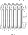
- Fig. 13 includes a partial cross section view of multiple TITUS elements 20 mounted in the outer case 14.
- the TITUS element 20 can be seen with the flange 72 connected with the outer case 14 in a counter bored portion 90.
- the counter bored portion 90 allows for the flange 72 to be set flush with an outer surface 92 of the outer case 14.
- the inner case 16 includes an inner surface 94.
- the inner surface 94 includes an inner surface receiver 96 for each of the TITUS elements 20.
- the receiver 96 allows for the end cap 60 to set within the inner surface receiver 96.
- the gap 98 can be from about 10 mil to about 12 mil.
- the gap 98 allows for thermal expansion of the TITUS element 20 and still provides for support to resist vibration from the flow forces of the external working fluid 23, such as gas turbine fluid flow during use.
- a technical advantage of the disclosed heat exchanger includes a double-walled tube structure, making the TITUS element structurally stiff.
- Another technical advantage of the disclosed heat exchanger includes fluid entering from the top, through the inner tube, to the bottom; at the bottom, the fluid travels up between the inner and outer tubes.
- Another technical advantage of the disclosed heat exchanger includes inside the annular passage are turbulator ribs that enhance heat transfer.
- Another technical advantage of the disclosed heat exchanger includes processed flow is collected at the top; hence, fluid enters and exits from the same end of the tube structure.
- Another technical advantage of the disclosed heat exchanger includes the outer tube contains forge rolled fins, or threads, to increase surface area and heat transfer.
- Another technical advantage of the disclosed heat exchanger includes TITUS elements having free floating ends allowing for thermal expansion, unlike conventional tube-style heat exchangers having the tubes fixed at both ends, requiring some means of compliance to alleviate thermal strain.
- Another technical advantage of the disclosed heat exchanger includes the TITUS element allows for simple assembly and plumbing, without the need of complex manifolds.
- Another technical advantage of the disclosed heat exchanger includes the entire TITUS element, and its internal components, are allowed to grow radially without inducing thermal strain.
- Another technical advantage of the disclosed heat exchanger includes the TITUS element is simply supported with a slip-fitting.
- TITUS elements are compact allowing for multiple end use such as for oil coolers or fuel cooling and used as immersive heaters/coolers.
Landscapes
- Engineering & Computer Science (AREA)
- Physics & Mathematics (AREA)
- Thermal Sciences (AREA)
- Mechanical Engineering (AREA)
- General Engineering & Computer Science (AREA)
- Geometry (AREA)
- Heat-Exchange Devices With Radiators And Conduit Assemblies (AREA)
Abstract
Description
- The present disclosure is directed to tube-in-tube heat exchanger, particularly tube-in-tube unified shell heat exchanger.
- Waste heat recovery heat exchangers are annular shaped, tube-style heat exchangers, situated aft of the turbine exit frame. Ideally, the operating fluid enters and exits from the outside diameter of that annulus, due to space constraints. The tubes are long and thin, but need to be rigid. Tubes must be allowed to thermally expand yet be constrained from excessive vibration.
- What is needed is a tube-in-tube unified shell heat exchanger that allows simple assembly and plumbing, without the need of complex manifolds.
- In accordance with the present disclosure, there is provided a tube-in-tube unified shell element heat exchanger comprising an outer tube structure comprising a tube wall defining a first end opposite a second end; the outer tube structure comprises an interior surface and an exterior surface opposite the interior surface; the interior surface includes an augmentation structure; the outer tube structure comprises an end cap connected to the second end of the tube wall; the outer tube structure comprises a top section proximate the first end; the top section includes a flange and a flow outlet; the tube wall of the outer tube structure connects with the top section proximate the flange to form an integral outer tube structure; an inner tube structure including a tubular shaped inner body defining an internal flow area, the inner tube structure including surface features formed on the exterior of the inner tube structure; the inner tube structure including a top ring connected to the exterior proximate an inlet port of the inner tube structure; inner tube structure includes an outlet port opposite the inlet port; wherein the top ring of the inner tube structure is connected with the top section of the outer tube structure; and a gap formed between the outer tube structure and the inner tube structure, the gap fluidly coupled between the inlet port and the flow outlet.
- A further embodiment of any of the foregoing embodiments may additionally and/or alternatively include the augmentation structure comprises helical shaped fins extending along the interior surface.
- A further embodiment of any of the foregoing embodiments may additionally and/or alternatively include the surface features comprise external flutes that spiral along a portion of the length of the inner tube structure.
- A further embodiment of any of the foregoing embodiments may additionally and/or alternatively include the augmentation structure along with the surface features are configured to provide vortex boundary mixing for an internal working fluid flowing between the exterior of the inner tube structure and interior surface of the outer tube structure.
- A further embodiment of any of the foregoing embodiments may additionally and/or alternatively include the gap is configured for each of the inner tube structure and the outer tube structure to independently expand/contract responsive to thermal gradients.
- A further embodiment of any of the foregoing embodiments may additionally and/or alternatively include the tube-in-tube unified shell element heat exchanger further comprising micro-fin surface features formed on the exterior surface of the outer tube structure.
- A further embodiment of any of the foregoing embodiments may additionally and/or alternatively include the surface features comprise spiraling external flutes having a spiral with a relative angle alpha to a longitudinal axis AA of the inner tube structure being from zero degrees to 30 degrees.
- In accordance with the present disclosure, there is provided An annular duct with tube-in-tube unified shell heat exchanger comprising the annular duct defined between an outer case and an inner case about an axis A; multiple tube-in-tube unified shell elements mounted to the outer case and extending into the annular duct radially relative to the axis A; each of the multiple tube-in-tube unified shell elements comprising an outer tube structure comprising a tube wall defining a first end opposite a second end; the outer tube structure comprises an interior surface and an exterior surface opposite the interior surface; the interior surface includes an augmentation structure; the outer tube structure; the outer tube structure comprises an end cap connected to the second end of the tube wall; the outer tube structure comprises a top section proximate the first end; the top section includes a flange and a flow outlet; the tube wall of the outer tube structure connects with the top section proximate the flange to form an integral outer tube structure; an inner tube structure including a tubular shaped inner body defining an internal flow area, the inner tube structure including surface features formed on the exterior of the inner tube structure; the inner tube structure including a top ring connected to the exterior proximate an inlet port of the inner tube structure; inner tube structure includes an outlet port opposite the inlet port; wherein the top ring of the inner tube structure is connected with the top section of the outer tube structure; and a gap formed between the outer tube structure and the inner tube structure, the gap fluidly coupled between the inlet port and the flow outlet.
- A further embodiment of any of the foregoing embodiments may additionally and/or alternatively include the augmentation structure comprises helical shaped fins extending along the interior surface.
- A further embodiment of any of the foregoing embodiments may additionally and/or alternatively include the surface features comprise external flutes that spiral along a portion of the length of the inner tube structure.
- A further embodiment of any of the foregoing embodiments may additionally and/or alternatively include the augmentation structure along with the surface features are configured to provide vortex boundary mixing for an internal working fluid flowing between the exterior of the inner tube structure and interior surface of the outer tube structure.
- A further embodiment of any of the foregoing embodiments may additionally and/or alternatively include the gap is configured for each of the inner tube structure and the outer tube structure to independently expand/contract responsive to thermal gradients.
- A further embodiment of any of the foregoing embodiments may additionally and/or alternatively include the annular duct with tube-in-tube unified shell heat exchanger further comprising micro-fin surface features formed on the exterior surface of the outer tube structure.
- In accordance with the present disclosure, there is provided a process for heat exchange through an annular duct with tube-in-tube unified shell element heat exchanger comprising flowing air through the annular duct defined between an outer case and an inner case about an axis A; mounting multiple tube-in-tube unified shell elements to the outer case extending into the annular duct radially relative to the axis A; each of the multiple tube-in-tube unified shell elements comprising an outer tube structure comprising a tube wall defining a first end opposite a second end; the outer tube structure comprises an interior surface and an exterior surface opposite the interior surface; the interior surface includes an augmentation structure; the outer tube structure; the outer tube structure comprises an end cap connected to the second end of the tube wall; the outer tube structure comprises a top section proximate the first end; the top section includes a flange and a flow outlet; the tube wall of the outer tube structure connects with the top section proximate the flange to form an integral outer tube structure; an inner tube structure including a tubular shaped inner body defining an internal flow area, the inner tube structure including surface features formed on the exterior of the inner tube structure; the inner tube structure including a top ring connected to the exterior proximate an inlet port of the inner tube structure; inner tube structure includes an outlet port opposite the inlet port; wherein the top ring of the inner tube structure is connected with the top section of the outer tube structure; a gap formed between the outer tube structure and the inner tube structure, fluidly coupling the gap between the inlet port and the flow outlet; flowing a working fluid into the inlet port through the inner tube structure; and flowing the working fluid through the gap and out of the flow outlet.
- A further embodiment of any of the foregoing embodiments may additionally and/or alternatively include the process further comprising mounting the flange flush with an outer surface of the outer case.
- A further embodiment of any of the foregoing embodiments may additionally and/or alternatively include the process further comprising forming vortex boundary mixing for the working fluid flowing through the gap past the augmentation structure and the surface features.
- A further embodiment of any of the foregoing embodiments may additionally and/or alternatively include the process further comprising setting the end cap within an inner surface receiver of the inner case; and forming a gap between the cap and the inner surface receiver.
- A further embodiment of any of the foregoing embodiments may additionally and/or alternatively include the process further comprising supplying and returning the working fluid from an exterior of the outer case.
- A further embodiment of any of the foregoing embodiments may additionally and/or alternatively include the working fluid is at pressures ranging from about 1 pound per square inch to about 5000 pounds per square inch
- A further embodiment of any of the foregoing embodiments may additionally and/or alternatively includethe working fluid is selected from the group consisting of a liquid or a supercritical fluid, air, liquid or super critical phase ammonia, liquid or super critical phase hydrogen, super critical phase carbon dioxide, and the like.
- Other details of the heat exchanger are set forth in the following detailed description and the accompanying drawings wherein like reference numerals depict like elements.
-
Fig. 1 is a cross sectional view of a schematic representation of an exemplary heat exchanger. -
Fig. 2 is an isometric view of a schematic representation of the exemplary heat exchanger. -
Fig. 3 is a partial cross sectional view of a schematic representation of the heat exchanger. -
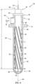
Fig. 4 is a cross-sectional view of a schematic representation of an exemplary heat exchanger element. -
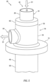
Fig. 5 is an isometric view of a schematic representation of an exemplary heat exchanger element. -
Fig. 6 is a cross-sectional view of a schematic representation of a portion of an exemplary heat exchanger element. -
Fig. 7 is a cross-sectional view of a schematic representation of an exemplary heat exchanger element -
Fig. 8 is a partial cross section isometric view of a schematic representation of a portion of an exemplary heat exchanger element. -
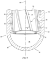
Fig. 9 is a partial cross section isometric view of a schematic representation of a portion of an exemplary heat exchanger element. -
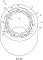
Fig. 10 is a partial cross section view of a schematic representation of a portion of an exemplary heat exchanger element. -
Fig. 11 is a partial cross section view of a schematic representation of a portion of an exemplary heat exchanger element. -
Fig. 12 is a partial cross section isometric view of a schematic representation of a portion of an exemplary heat exchanger. -
Fig. 13 is a partial cross section isometric view of a schematic representation of a portion of an exemplary heat exchanger element. - Referring now to
Figs. 1-3 , there is illustrated anexemplary heat exchanger 10. In an exemplary embodiment, theheat exchanger 10 can be a tube-in-tube unified shell (TITUS)heat exchanger 10. Theheat exchanger 10 can be installed from an exterior of anannular duct 12. Theannular duct 12 can be defined between anouter case 14 enveloping aninner case 16 about an axis A. Theheat exchanger 10 can include multiplesmall diameter tubes 18 assembled as tube-in-tube elements 20. Thesmall diameter tubes 18 can have an outside diameter of less than 0.100 inches. An internal workingfluid 22 that flows through the tube-in-tube elements 20 can include a liquid or a supercritical fluid, such as for example, air (gas), ammonia (liquid/super critical), hydrogen (liquid/super critical), carbon dioxide (super critical), and the like. An external workingfluid 23, such as air can be flowing exterior of thetube elements 20, for example in an air duct of a gas turbine engine. In an exemplary embodiment, the internal workingfluid 22 can be at high pressure, for example ranging from about 1 pound per square inch to about 5000 pounds per square inch. - In an exemplary embodiment, the
tube elements 20 can be inserted from the exterior of theouter case 14 through theouter case 14 into theannular duct 12. This design allows for aheat exchanger 10 with an orientation and plumbing of the internal workingfluid 22 to be supplied and returned from one side of theouter case 14, such as the exterior of theannular duct 12. For example, as shown, the internal workingfluid 22 can be supplied and returned from exterior of theouter case 14. - Referring also to
Figs. 4-13 , details of the tube-in-tube unifiedshell elements 20 are disclosed. The tube-in-tube unified shell elements or simplyTITUS elements 20 include aninner tube structure 24 disposed within anouter tube structure 26. Theinner tube structure 24 includes a tubular shapedinner body 28 having aninternal flow area 30. In an exemplary embodiment, theinternal flow area 30 can be defined by asmooth bore 32 inside diameter of theinner tube structure 24, as seen inFigs. 5 and7 . Theinner tube structure 24 includessurface features 34 disposed and/or formed on the exterior/outer diameter 38 of theinner tube structure 24. In an exemplary embodiment, thesurface features 34 can be formed as external flutes orguide fins 34 that spiral along a portion of the length L of theinner tube structure 24 exposed to the working fluid. Theinner tube structure 24 can be formed from thick walled tube stock. Thesurface features 34 can be machined into shape, such as the spiralingexternal flutes 34. - A
flow passage 39 can be defined between any twoadjacent flutes 34. The height offlow passage 39, H = (OD-ID)/2 of the annulus defined as the space between theouter tube structure 26 andinner tube structure 24, specifically, the inside diameter of theouter tube structure 26 shown at theinterior surface 48 to theoutside diameter 38 of theinner tube structure 24. The width W of thispassage 39 is defined as the mean arc length betweenflutes 34, such that, the aspect ratio, AR = W/H is between 2-3. The relative angle alpha (a) of the spiral S to the longitudinal axis AA of theinner tube structure 24 can be from about between 0 degrees (straight) and 30 degrees (seeFig. 9 ). Thesurface features 34 are configured to provide theflow passage 39 for the internal workingfluid 22 flowing along the exterior of theinner tube structure 24. - The
inner tube structure 24 includes atop ring 40 shaped as a cylinder configured to couple to the exterior/outer diameter 38 proximate aninlet port 42 of theinner tube structure 24. Thetop ring 40 facilitates connecting theinner tube structure 24 with theouter tube structure 26. Theinner tube structure 24 includes anoutlet port 44 opposite theinlet port 42. The internal workingfluid 22 can enter theinlet port 42, flow through theinternal flow area 30 and discharge from theoutlet port 44 of theinner tube structure 24. - The
outer tube structure 26 includes a longitudinalcylindrical tube wall 46. Thetube wall 46 of theouter tube structure 26 includes aninterior surface 48 and anexterior surface 50 opposite theinterior surface 48. Theinterior surface 48 includes anaugmentation structure 52. Theaugmentation structure 52 can be formed as helical shaped fins that extend along theinterior surface 48. Theaugmentation structure 52 can be formed similarly to rifling of a gun barrel, for example with a helical broaching tool to form ribs. Theaugmentation structure 52 can be continuous or discontinuous. Theaugmentation structure 52 along with the surface features 34 are configured to provide vortex boundary mixing for the internal workingfluid 22 flowing between the exterior of theinner tube structure 24 andinterior surface 48 of theouter tube structure 26. In an exemplary embodiment, micro-fin surface features 54 can be formed on theexterior surface 50 as seen inFig. 11 . The micro-fin surface features 54 are configured to increase the surface area of thetube wall 46exterior surface 50. Thetube wall 46 can have small diameter, or hypodermic tubing with outside diameter (OD) of less than 0.100 inch. The wall thickness can be less than or equal to 0.010 inch, and can be approximately 0.005 inch. The micro-fin surface features can have a thickness of less than or equal to 0.010 inch. In an exemplary embodiment, the micro-fin surface features 54 have a height of less than or equal to 0.003 inch. In another exemplary embodiment, the micro-fin surface features 54 can range from 0.002 inch to 0.010 inch tall. The micro-fin surface features can have a height/thickness aspect ratio (AR): 1 < AR < 3. In an exemplary embodiment, the materials of thetube wall 46 can include stainless steel; Inconel®, and Hastelloy®. Inconel® is a class of nickel-chrome-based super alloys characterized by high corrosion resistance, oxidation resistance, strength at high temperatures, and creep resistance. Hastelloy® is a corrosion-resistant nickel alloy that contains other chemical elements such as chromium and molybdenum. This material has high temperature resistance and exceptional corrosion resistance. - The micro-fin surface features 54 can be formed by use of forge-rolling. Cold forge-rolling is accomplished via use of a center support mandrel. Other processes can include chemical etching/machining of external surface, laser etching or conventional machining, such as on a lathe and machining via wire-EDM.
- The
outer tube structure 26 includes afirst end 56 opposite asecond end 58. Thefirst end 56 connects with thetop ring 40 proximate theinlet port 42 of theinner tube structure 24. Thesecond end 58 includes anend cap 60 with a hemispherical or domed shapeinterior surface 48. Theend cap 60 is configured to turn the internal workingfluid 22 after exiting theoutlet port 44. The internal workingfluid 22 changes direction and flows through theflow passage 39 and in part through adiametral tolerance 62 in between theinner tube structure 24 andouter tube structure 26 toward aflow outlet 64 of theouter tube structure 26. As the internal workingfluid 22 flows through theflow passage 39, the internal workingfluid 22 is influenced by each of theaugmentation structure 52, and the surface features 34, causing the internal workingfluid 22 to swirl and mix with vortex boundary mixing as depicted inFig. 10 byarrows 66. The mixing provides for additional heat transfer between theinner tube structure 24 and theouter tube structure 26 which lessens the thermal gradient at thesecond end 58. Thediametral tolerance 62 is configured to allow for each of theinner tube structure 24 andouter tube structure 26 to independently expand/contract responsive to thermal gradients. In an exemplary embodiment, thediametral tolerance 62 can range from 0.002 inch to 0.003 inch. - In an exemplary embodiment, the internal working
fluid 22 can discharge out of theflow outlet 64 and anadditional flow outlet 68 as seen inFig. 8 . Theadditional flow outlet 68 can be formed in theouter tube structure 26. Theadditional flow outlet 68 would require manifold devices to guide the internal workingfluid 22. - The
outer tube structure 26 includes atop section 70 proximate thefirst end 56. Thetop section 70 includes aflange 72 and theflow outlet 64. Thetube wall 46 of theouter tube structure 26 connects with thetop section 70 proximate theflange 72 to form the integralouter tube structure 26. Theend cap 60 can be connected to thetube wall 46 of theouter tube structure 26 proximate thesecond end 58. Theouter tube structure 26 includes areceiver 74 proximate thefirst end 56. Theinner tube structure 24 inserts through thereceiver 74 and connects with theouter tube structure 26 via thetop ring 40. - The
tubular body 28 of theinner tube structure 24 can be constructed of a thinner wall thickness since theinner tube structure 24 does not bear the primary loads created by the gas turbine annularduct fluid flow 23. When the aerodynamic loads applied by the external workingfluid 23 to theouter case 14 cause deflection, theinner case 16 andouter case 14 structures will come into contact. The interaction between them will form a reinforcement, hence the term unified shell. Theinner case 16 structure may be a load bearing structure. - In an exemplary embodiment, as seen in
Fig. 12 , amulti-layered manifold 78 can be employed to direct the internal workingfluid 22. Themulti-layered manifold 78 can include aninner manifold 80 that connects with theouter tube structure 26. Amiddle manifold 82 is connected with thetop ring 40 forming afirst flow space 84 for theflow outlet 64 and the discharge of the internal workingfluid 22. Anouter manifold 86 is located to form asecond flow space 88 fluidly coupled to theinlet port 42, for the ingress of the internal workingfluid 22. -
Fig. 13 includes a partial cross section view ofmultiple TITUS elements 20 mounted in theouter case 14. TheTITUS element 20 can be seen with theflange 72 connected with theouter case 14 in a counterbored portion 90. The counterbored portion 90 allows for theflange 72 to be set flush with anouter surface 92 of theouter case 14. Theinner case 16 includes aninner surface 94. Theinner surface 94 includes aninner surface receiver 96 for each of theTITUS elements 20. Thereceiver 96 allows for theend cap 60 to set within theinner surface receiver 96. There can be agap 98 between thecap 60 and theinner surface receiver 96. Thegap 98 can be from about 10 mil to about 12 mil. Thegap 98 allows for thermal expansion of theTITUS element 20 and still provides for support to resist vibration from the flow forces of the external workingfluid 23, such as gas turbine fluid flow during use. - A technical advantage of the disclosed heat exchanger includes a double-walled tube structure, making the TITUS element structurally stiff.
- Another technical advantage of the disclosed heat exchanger includes fluid entering from the top, through the inner tube, to the bottom; at the bottom, the fluid travels up between the inner and outer tubes.
- Another technical advantage of the disclosed heat exchanger includes inside the annular passage are turbulator ribs that enhance heat transfer.
- Another technical advantage of the disclosed heat exchanger includes processed flow is collected at the top; hence, fluid enters and exits from the same end of the tube structure.
- Another technical advantage of the disclosed heat exchanger includes the outer tube contains forge rolled fins, or threads, to increase surface area and heat transfer.
- Another technical advantage of the disclosed heat exchanger includes TITUS elements having free floating ends allowing for thermal expansion, unlike conventional tube-style heat exchangers having the tubes fixed at both ends, requiring some means of compliance to alleviate thermal strain.
- Another technical advantage of the disclosed heat exchanger includes the TITUS element allows for simple assembly and plumbing, without the need of complex manifolds.
- Another technical advantage of the disclosed heat exchanger includes the entire TITUS element, and its internal components, are allowed to grow radially without inducing thermal strain.
- Another technical advantage of the disclosed heat exchanger includes the TITUS element is simply supported with a slip-fitting.
- Another technical advantage of the disclosed heat exchanger includes TITUS elements are compact allowing for multiple end use such as for oil coolers or fuel cooling and used as immersive heaters/coolers.
- There has been provided a heat exchanger. While the heat exchanger has been described in the context of specific embodiments thereof, other unforeseen alternatives, modifications, and variations may become apparent to those skilled in the art having read the foregoing description. Accordingly, it is intended to embrace those alternatives, modifications, and variations which fall within the broad scope of the appended claims.
Claims (15)
- A tube-in-tube unified shell element heat exchanger comprising:an outer tube structure comprising a tube wall defining a first end opposite a second end; the outer tube structure comprises an interior surface and an exterior surface opposite the interior surface; the interior surface includes an augmentation structure; the outer tube structure comprises an end cap connected to the second end of the tube wall; the outer tube structure comprises a top section proximate the first end; the top section includes a flange and a flow outlet; the tube wall of the outer tube structure connects with the top section proximate the flange to form an integral outer tube structure;an inner tube structure including a tubular shaped inner body defining an internal flow area, the inner tube structure including surface features formed on the exterior of the inner tube structure; the inner tube structure including a top ring connected to the exterior proximate an inlet port of the inner tube structure; inner tube structure includes an outlet port opposite the inlet port; wherein the top ring of the inner tube structure is connected with the top section of the outer tube structure; anda gap formed between the outer tube structure and the inner tube structure, the gap fluidly coupled between the inlet port and the flow outlet.
- The tube-in-tube unified shell element heat exchanger according to claim 1, wherein said augmentation structure comprises helical shaped fins extending along the interior surface.
- The tube-in-tube unified shell element heat exchanger according to claim 1 or 2, wherein the surface features comprise external flutes that spiral along a portion of the length of the inner tube structure.
- The tube-in-tube unified shell element heat exchanger according to any one of claims 1 to 3, wherein the augmentation structure along with the surface features are configured to provide vortex boundary mixing for an internal working fluid flowing between the exterior of the inner tube structure and interior surface of the outer tube structure.
- The tube-in-tube unified shell element heat exchanger according to any one of claims 1 to 4, wherein the gap is configured for each of the inner tube structure and the outer tube structure to independently expand/contract responsive to thermal gradients.
- The tube-in-tube unified shell element heat exchanger according to any one of claims 1 to 5, further comprising:
micro-fin surface features formed on the exterior surface of the outer tube structure. - The tube-in-tube unified shell element heat exchanger according to any one of claims 1 to 6, wherein the surface features comprise spiraling external flutes having a spiral with a relative angle alpha to a longitudinal axis AA of the inner tube structure being from zero degrees to 30 degrees.
- An annular duct with tube-in-tube unified shell heat exchanger comprising:the annular duct defined between an outer case and an inner case about an axis A;multiple tube-in-tube unified shell elements mounted to the outer case and extending into the annular duct radially relative to the axis A;each of the multiple tube-in-tube unified shell elements having a configuration according to any one of claims 1 to 7.
- A process for heat exchange through an annular duct with tube-in-tube unified shell element heat exchanger comprising:flowing air through the annular duct defined between an outer case and an inner case about an axis A;mounting multiple tube-in-tube unified shell elements to the outer case extending into the annular duct radially relative to the axis A;each of the multiple tube-in-tube unified shell elements comprising:an outer tube structure comprising a tube wall defining a first end opposite a second end; the outer tube structure comprises an interior surface and an exterior surface opposite the interior surface; the interior surface includes an augmentation structure; the outer tube structure; the outer tube structure comprises an end cap connected to the second end of the tube wall; the outer tube structure comprises a top section proximate the first end; the top section includes a flange and a flow outlet; the tube wall of the outer tube structure connects with the top section proximate the flange to form an integral outer tube structure;an inner tube structure including a tubular shaped inner body defining an internal flow area, the inner tube structure including surface features formed on the exterior of the inner tube structure; the inner tube structure including a top ring connected to the exterior proximate an inlet port of the inner tube structure; inner tube structure includes an outlet port opposite the inlet port; wherein the top ring of the inner tube structure is connected with the top section of the outer tube structure;a gap formed between the outer tube structure and the inner tube structure, fluidly coupling the gap between the inlet port and the flow outlet;flowing a working fluid into the inlet port through the inner tube structure; andflowing the working fluid through the gap and out of the flow outlet.
- The process of claim 9, further comprising:
mounting the flange flush with an outer surface of the outer case. - The process of claim 9 or 10, further comprising:
forming vortex boundary mixing for the working fluid flowing through the gap past the augmentation structure and the surface features. - The process of any one of claims 9 to 11, further comprising:setting the end cap within an inner surface receiver of the inner case; andforming a gap between the cap and the inner surface receiver.
- The process of any one of claims 9 to 12, further comprising:
supplying and returning the working fluid from an exterior of the outer case. - The process of any one of claims 9 to 13, wherein the working fluid is at pressures ranging from about 1 pound per square inch to about 5000 pounds per square inch.
- The process of any one of claims 9 to 14, wherein said working fluid is selected from the group consisting of a liquid or a supercritical fluid, air, liquid or super critical phase ammonia, liquid or super critical phase hydrogen, super critical phase carbon dioxide, and the like.
Applications Claiming Priority (1)
| Application Number | Priority Date | Filing Date | Title |
|---|---|---|---|
| US17/960,857 US12215930B2 (en) | 2022-10-06 | 2022-10-06 | Tube-in-tube unified shell heat exchanger |
Publications (2)
| Publication Number | Publication Date |
|---|---|
| EP4350268A1 true EP4350268A1 (en) | 2024-04-10 |
| EP4350268B1 EP4350268B1 (en) | 2024-09-11 |
Family
ID=88287427
Family Applications (1)
| Application Number | Title | Priority Date | Filing Date |
|---|---|---|---|
| EP23201569.3A Active EP4350268B1 (en) | 2022-10-06 | 2023-10-04 | Tube-in-tube unified shell heat exchanger |
Country Status (2)
| Country | Link |
|---|---|
| US (1) | US12215930B2 (en) |
| EP (1) | EP4350268B1 (en) |
Citations (6)
| Publication number | Priority date | Publication date | Assignee | Title |
|---|---|---|---|---|
| US4479534A (en) * | 1981-12-07 | 1984-10-30 | The Air Preheater Company, Inc. | Transparent radiation recuperator |
| US5269133A (en) * | 1991-06-18 | 1993-12-14 | General Electric Company | Heat exchanger for cooling a gas turbine |
| RU2027969C1 (en) * | 1993-02-24 | 1995-01-27 | Научно-производственное предприятие "ТАРК" | Heat exchange element |
| JP2630427B2 (en) * | 1988-05-20 | 1997-07-16 | 株式会社荏原製作所 | Ceramic bayonet heat exchanger |
| WO2019120980A1 (en) * | 2017-12-18 | 2019-06-27 | Webasto SE | Counter-current heat exchanger |
| WO2022150600A1 (en) * | 2021-01-08 | 2022-07-14 | Sani-Tech West, Inc. | Process cooling rod |
Family Cites Families (15)
| Publication number | Priority date | Publication date | Assignee | Title |
|---|---|---|---|---|
| US2341319A (en) * | 1941-10-31 | 1944-02-08 | Lummus Co | Heat exchanger |
| US2937855A (en) * | 1958-09-11 | 1960-05-24 | Frank D Hazen | Recuperator structures |
| US3403726A (en) * | 1965-12-20 | 1968-10-01 | Hazen Engineering Company | Spray and negative pressure cooling system |
| US3586098A (en) * | 1970-02-05 | 1971-06-22 | American Schack Co | Concentric tube heat exchanges |
| US3887003A (en) * | 1972-05-17 | 1975-06-03 | Foster Wheeler Corp | Bayonet tube heat exchanger |
| US4106556A (en) * | 1976-11-26 | 1978-08-15 | Thermal Transfer, Division Of Kleinewefers | Ceramic tube recuperators |
| US4269266A (en) * | 1979-08-23 | 1981-05-26 | United States Steel Corporation | Recuperator tube construction |
| US4548257A (en) * | 1982-02-23 | 1985-10-22 | Williamson William R | Bayonet tube heat exchanger |
| FR2563900B1 (en) | 1984-05-04 | 1986-10-31 | Novatome | DOUBLE WALL TUBE FOR A HEAT EXCHANGER AND METHOD FOR PRODUCING THE SAME |
| IT1184767B (en) * | 1985-04-23 | 1987-10-28 | Tycon Spa | HEAT EXCHANGER WITH EXTERNALLY GLAZED BAYONET PIPES |
| SE508135C2 (en) * | 1996-12-19 | 1998-08-31 | Sandvik Ab | Recuperator for ovens, in particular continuous water-type glass ovens |
| JP2009162395A (en) | 2007-12-28 | 2009-07-23 | Showa Denko Kk | Double-wall-tube heat exchanger |
| JP5504050B2 (en) | 2009-06-30 | 2014-05-28 | 株式会社ケーヒン・サーマル・テクノロジー | Double tube heat exchanger and method for manufacturing the same |
| WO2012116448A1 (en) * | 2011-03-01 | 2012-09-07 | Dana Canada Corporation | Coaxial gas-liquid heat exchanger with thermal expansion connector |
| GB201419963D0 (en) | 2014-11-10 | 2014-12-24 | Rolls Royce Plc | Heat exchanger |
-
2022
- 2022-10-06 US US17/960,857 patent/US12215930B2/en active Active
-
2023
- 2023-10-04 EP EP23201569.3A patent/EP4350268B1/en active Active
Patent Citations (6)
| Publication number | Priority date | Publication date | Assignee | Title |
|---|---|---|---|---|
| US4479534A (en) * | 1981-12-07 | 1984-10-30 | The Air Preheater Company, Inc. | Transparent radiation recuperator |
| JP2630427B2 (en) * | 1988-05-20 | 1997-07-16 | 株式会社荏原製作所 | Ceramic bayonet heat exchanger |
| US5269133A (en) * | 1991-06-18 | 1993-12-14 | General Electric Company | Heat exchanger for cooling a gas turbine |
| RU2027969C1 (en) * | 1993-02-24 | 1995-01-27 | Научно-производственное предприятие "ТАРК" | Heat exchange element |
| WO2019120980A1 (en) * | 2017-12-18 | 2019-06-27 | Webasto SE | Counter-current heat exchanger |
| WO2022150600A1 (en) * | 2021-01-08 | 2022-07-14 | Sani-Tech West, Inc. | Process cooling rod |
Also Published As
| Publication number | Publication date |
|---|---|
| US20240118034A1 (en) | 2024-04-11 |
| EP4350268B1 (en) | 2024-09-11 |
| US12215930B2 (en) | 2025-02-04 |
Similar Documents
| Publication | Publication Date | Title |
|---|---|---|
| US10914527B2 (en) | Tube bundle heat exchanger | |
| US7767172B2 (en) | Shell-type reactor with radial baffles | |
| EP3944889B1 (en) | Annular heat exchanger | |
| US7302794B2 (en) | Rocket engine member and a method for manufacturing a rocket engine member | |
| US6789316B2 (en) | Method for manufacturing outlet nozzles for rocket engines | |
| CN110793356A (en) | Compact multi-partition heat exchanger | |
| CN110494208A (en) | Heat Exchangers and Reactors | |
| EP4350268B1 (en) | Tube-in-tube unified shell heat exchanger | |
| JP6793078B2 (en) | Heat exchanger | |
| US12135172B2 (en) | Duct heat exchanger | |
| US3362468A (en) | Surface condenser | |
| CN111081397B (en) | An integrated nuclear reactor primary circuit heat exchanger | |
| JP2007113795A (en) | Multitubular heat exchanger for exhaust gas cooling device | |
| CA2456865C (en) | Device for introducing hot gas into a heating surface pipe of a waste heat boiler | |
| US11686535B2 (en) | Heat exchanger | |
| EP4509793A1 (en) | Shell member for heat exchanger | |
| CN115773692A (en) | Refrigerant distribution devices and plate heat exchangers for plate heat exchangers | |
| CN112588207A (en) | Vertical radial flow reactor | |
| CN220304333U (en) | Tube type graphite heat exchanger with high heat exchange efficiency | |
| CN119778104B (en) | A piping arrangement structure for the high-pressure compressor rear casing of a small to medium-sized gas turbine. | |
| CN223992053U (en) | High-temperature corrosion-resistant corrugated pipe expansion joint for liquid metal environment | |
| US11788793B1 (en) | Recuperator with balanced and floating core | |
| CN119573423A (en) | Wall-integrated 3D printed high-efficiency heat exchange cylinder with teardrop-shaped cross-section flow channel | |
| CN121520889A (en) | Low-temperature heat exchangers and their control methods | |
| CN121383747A (en) | Turbine pump integrated heat exchanger |
Legal Events
| Date | Code | Title | Description |
|---|---|---|---|
| PUAI | Public reference made under article 153(3) epc to a published international application that has entered the european phase |
Free format text: ORIGINAL CODE: 0009012 |
|
| STAA | Information on the status of an ep patent application or granted ep patent |
Free format text: STATUS: THE APPLICATION HAS BEEN PUBLISHED |
|
| AK | Designated contracting states |
Kind code of ref document: A1 Designated state(s): AL AT BE BG CH CY CZ DE DK EE ES FI FR GB GR HR HU IE IS IT LI LT LU LV MC ME MK MT NL NO PL PT RO RS SE SI SK SM TR |
|
| RAP3 | Party data changed (applicant data changed or rights of an application transferred) |
Owner name: RTX CORPORATION |
|
| STAA | Information on the status of an ep patent application or granted ep patent |
Free format text: STATUS: REQUEST FOR EXAMINATION WAS MADE |
|
| GRAP | Despatch of communication of intention to grant a patent |
Free format text: ORIGINAL CODE: EPIDOSNIGR1 |
|
| STAA | Information on the status of an ep patent application or granted ep patent |
Free format text: STATUS: GRANT OF PATENT IS INTENDED |
|
| 17P | Request for examination filed |
Effective date: 20240513 |
|
| RBV | Designated contracting states (corrected) |
Designated state(s): AL AT BE BG CH CY CZ DE DK EE ES FI FR GB GR HR HU IE IS IT LI LT LU LV MC ME MK MT NL NO PL PT RO RS SE SI SK SM TR |
|
| INTG | Intention to grant announced |
Effective date: 20240618 |
|
| GRAS | Grant fee paid |
Free format text: ORIGINAL CODE: EPIDOSNIGR3 |
|
| GRAA | (expected) grant |
Free format text: ORIGINAL CODE: 0009210 |
|
| STAA | Information on the status of an ep patent application or granted ep patent |
Free format text: STATUS: THE PATENT HAS BEEN GRANTED |
|
| AK | Designated contracting states |
Kind code of ref document: B1 Designated state(s): AL AT BE BG CH CY CZ DE DK EE ES FI FR GB GR HR HU IE IS IT LI LT LU LV MC ME MK MT NL NO PL PT RO RS SE SI SK SM TR |
|
| REG | Reference to a national code |
Ref country code: GB Ref legal event code: FG4D |
|
| REG | Reference to a national code |
Ref country code: CH Ref legal event code: EP |
|
| REG | Reference to a national code |
Ref country code: DE Ref legal event code: R096 Ref document number: 602023000543 Country of ref document: DE |
|
| REG | Reference to a national code |
Ref country code: IE Ref legal event code: FG4D |
|
| REG | Reference to a national code |
Ref country code: LT Ref legal event code: MG9D |
|
| PG25 | Lapsed in a contracting state [announced via postgrant information from national office to epo] |
Ref country code: NO Free format text: LAPSE BECAUSE OF FAILURE TO SUBMIT A TRANSLATION OF THE DESCRIPTION OR TO PAY THE FEE WITHIN THE PRESCRIBED TIME-LIMIT Effective date: 20241211 |
|
| REG | Reference to a national code |
Ref country code: NL Ref legal event code: MP Effective date: 20240911 |
|
| PG25 | Lapsed in a contracting state [announced via postgrant information from national office to epo] |
Ref country code: GR Free format text: LAPSE BECAUSE OF FAILURE TO SUBMIT A TRANSLATION OF THE DESCRIPTION OR TO PAY THE FEE WITHIN THE PRESCRIBED TIME-LIMIT Effective date: 20241212 Ref country code: FI Free format text: LAPSE BECAUSE OF FAILURE TO SUBMIT A TRANSLATION OF THE DESCRIPTION OR TO PAY THE FEE WITHIN THE PRESCRIBED TIME-LIMIT Effective date: 20240911 |
|
| PG25 | Lapsed in a contracting state [announced via postgrant information from national office to epo] |
Ref country code: BG Free format text: LAPSE BECAUSE OF FAILURE TO SUBMIT A TRANSLATION OF THE DESCRIPTION OR TO PAY THE FEE WITHIN THE PRESCRIBED TIME-LIMIT Effective date: 20240911 |
|
| PG25 | Lapsed in a contracting state [announced via postgrant information from national office to epo] |
Ref country code: LV Free format text: LAPSE BECAUSE OF FAILURE TO SUBMIT A TRANSLATION OF THE DESCRIPTION OR TO PAY THE FEE WITHIN THE PRESCRIBED TIME-LIMIT Effective date: 20240911 |
|
| PG25 | Lapsed in a contracting state [announced via postgrant information from national office to epo] |
Ref country code: HR Free format text: LAPSE BECAUSE OF FAILURE TO SUBMIT A TRANSLATION OF THE DESCRIPTION OR TO PAY THE FEE WITHIN THE PRESCRIBED TIME-LIMIT Effective date: 20240911 |
|
| PG25 | Lapsed in a contracting state [announced via postgrant information from national office to epo] |
Ref country code: RS Free format text: LAPSE BECAUSE OF FAILURE TO SUBMIT A TRANSLATION OF THE DESCRIPTION OR TO PAY THE FEE WITHIN THE PRESCRIBED TIME-LIMIT Effective date: 20241211 Ref country code: ES Free format text: LAPSE BECAUSE OF FAILURE TO SUBMIT A TRANSLATION OF THE DESCRIPTION OR TO PAY THE FEE WITHIN THE PRESCRIBED TIME-LIMIT Effective date: 20240911 |
|
| PG25 | Lapsed in a contracting state [announced via postgrant information from national office to epo] |
Ref country code: RS Free format text: LAPSE BECAUSE OF FAILURE TO SUBMIT A TRANSLATION OF THE DESCRIPTION OR TO PAY THE FEE WITHIN THE PRESCRIBED TIME-LIMIT Effective date: 20241211 Ref country code: NO Free format text: LAPSE BECAUSE OF FAILURE TO SUBMIT A TRANSLATION OF THE DESCRIPTION OR TO PAY THE FEE WITHIN THE PRESCRIBED TIME-LIMIT Effective date: 20241211 Ref country code: LV Free format text: LAPSE BECAUSE OF FAILURE TO SUBMIT A TRANSLATION OF THE DESCRIPTION OR TO PAY THE FEE WITHIN THE PRESCRIBED TIME-LIMIT Effective date: 20240911 Ref country code: HR Free format text: LAPSE BECAUSE OF FAILURE TO SUBMIT A TRANSLATION OF THE DESCRIPTION OR TO PAY THE FEE WITHIN THE PRESCRIBED TIME-LIMIT Effective date: 20240911 Ref country code: GR Free format text: LAPSE BECAUSE OF FAILURE TO SUBMIT A TRANSLATION OF THE DESCRIPTION OR TO PAY THE FEE WITHIN THE PRESCRIBED TIME-LIMIT Effective date: 20241212 Ref country code: FI Free format text: LAPSE BECAUSE OF FAILURE TO SUBMIT A TRANSLATION OF THE DESCRIPTION OR TO PAY THE FEE WITHIN THE PRESCRIBED TIME-LIMIT Effective date: 20240911 Ref country code: ES Free format text: LAPSE BECAUSE OF FAILURE TO SUBMIT A TRANSLATION OF THE DESCRIPTION OR TO PAY THE FEE WITHIN THE PRESCRIBED TIME-LIMIT Effective date: 20240911 Ref country code: BG Free format text: LAPSE BECAUSE OF FAILURE TO SUBMIT A TRANSLATION OF THE DESCRIPTION OR TO PAY THE FEE WITHIN THE PRESCRIBED TIME-LIMIT Effective date: 20240911 |
|
| REG | Reference to a national code |
Ref country code: AT Ref legal event code: MK05 Ref document number: 1723039 Country of ref document: AT Kind code of ref document: T Effective date: 20240911 |
|
| PG25 | Lapsed in a contracting state [announced via postgrant information from national office to epo] |
Ref country code: NL Free format text: LAPSE BECAUSE OF FAILURE TO SUBMIT A TRANSLATION OF THE DESCRIPTION OR TO PAY THE FEE WITHIN THE PRESCRIBED TIME-LIMIT Effective date: 20240911 |
|
| PG25 | Lapsed in a contracting state [announced via postgrant information from national office to epo] |
Ref country code: IS Free format text: LAPSE BECAUSE OF FAILURE TO SUBMIT A TRANSLATION OF THE DESCRIPTION OR TO PAY THE FEE WITHIN THE PRESCRIBED TIME-LIMIT Effective date: 20250111 Ref country code: PT Free format text: LAPSE BECAUSE OF FAILURE TO SUBMIT A TRANSLATION OF THE DESCRIPTION OR TO PAY THE FEE WITHIN THE PRESCRIBED TIME-LIMIT Effective date: 20250113 |
|
| PG25 | Lapsed in a contracting state [announced via postgrant information from national office to epo] |
Ref country code: SM Free format text: LAPSE BECAUSE OF FAILURE TO SUBMIT A TRANSLATION OF THE DESCRIPTION OR TO PAY THE FEE WITHIN THE PRESCRIBED TIME-LIMIT Effective date: 20240911 Ref country code: RO Free format text: LAPSE BECAUSE OF FAILURE TO SUBMIT A TRANSLATION OF THE DESCRIPTION OR TO PAY THE FEE WITHIN THE PRESCRIBED TIME-LIMIT Effective date: 20240911 |
|
| PG25 | Lapsed in a contracting state [announced via postgrant information from national office to epo] |
Ref country code: AT Free format text: LAPSE BECAUSE OF FAILURE TO SUBMIT A TRANSLATION OF THE DESCRIPTION OR TO PAY THE FEE WITHIN THE PRESCRIBED TIME-LIMIT Effective date: 20240911 Ref country code: EE Free format text: LAPSE BECAUSE OF FAILURE TO SUBMIT A TRANSLATION OF THE DESCRIPTION OR TO PAY THE FEE WITHIN THE PRESCRIBED TIME-LIMIT Effective date: 20240911 |
|
| PG25 | Lapsed in a contracting state [announced via postgrant information from national office to epo] |
Ref country code: CZ Free format text: LAPSE BECAUSE OF FAILURE TO SUBMIT A TRANSLATION OF THE DESCRIPTION OR TO PAY THE FEE WITHIN THE PRESCRIBED TIME-LIMIT Effective date: 20240911 Ref country code: PL Free format text: LAPSE BECAUSE OF FAILURE TO SUBMIT A TRANSLATION OF THE DESCRIPTION OR TO PAY THE FEE WITHIN THE PRESCRIBED TIME-LIMIT Effective date: 20240911 |
|
| PG25 | Lapsed in a contracting state [announced via postgrant information from national office to epo] |
Ref country code: SK Free format text: LAPSE BECAUSE OF FAILURE TO SUBMIT A TRANSLATION OF THE DESCRIPTION OR TO PAY THE FEE WITHIN THE PRESCRIBED TIME-LIMIT Effective date: 20240911 Ref country code: IT Free format text: LAPSE BECAUSE OF FAILURE TO SUBMIT A TRANSLATION OF THE DESCRIPTION OR TO PAY THE FEE WITHIN THE PRESCRIBED TIME-LIMIT Effective date: 20240911 |
|
| REG | Reference to a national code |
Ref country code: DE Ref legal event code: R097 Ref document number: 602023000543 Country of ref document: DE |
|
| PG25 | Lapsed in a contracting state [announced via postgrant information from national office to epo] |
Ref country code: MC Free format text: LAPSE BECAUSE OF FAILURE TO SUBMIT A TRANSLATION OF THE DESCRIPTION OR TO PAY THE FEE WITHIN THE PRESCRIBED TIME-LIMIT Effective date: 20240911 |
|
| PG25 | Lapsed in a contracting state [announced via postgrant information from national office to epo] |
Ref country code: DK Free format text: LAPSE BECAUSE OF FAILURE TO SUBMIT A TRANSLATION OF THE DESCRIPTION OR TO PAY THE FEE WITHIN THE PRESCRIBED TIME-LIMIT Effective date: 20240911 |
|
| PLBE | No opposition filed within time limit |
Free format text: ORIGINAL CODE: 0009261 |
|
| STAA | Information on the status of an ep patent application or granted ep patent |
Free format text: STATUS: NO OPPOSITION FILED WITHIN TIME LIMIT |
|
| 26N | No opposition filed |
Effective date: 20250612 |
|
| PG25 | Lapsed in a contracting state [announced via postgrant information from national office to epo] |
Ref country code: SE Free format text: LAPSE BECAUSE OF FAILURE TO SUBMIT A TRANSLATION OF THE DESCRIPTION OR TO PAY THE FEE WITHIN THE PRESCRIBED TIME-LIMIT Effective date: 20240911 |
|
| PGFP | Annual fee paid to national office [announced via postgrant information from national office to epo] |
Ref country code: FR Payment date: 20250924 Year of fee payment: 3 |
|
| PGFP | Annual fee paid to national office [announced via postgrant information from national office to epo] |
Ref country code: DE Payment date: 20250923 Year of fee payment: 3 |