EP4350257A1 - Refrigerant leakage determination device, control device, refrigerant leakage determination program, and refrigerant leakage determination method - Google Patents
Refrigerant leakage determination device, control device, refrigerant leakage determination program, and refrigerant leakage determination method Download PDFInfo
- Publication number
- EP4350257A1 EP4350257A1 EP21943036.0A EP21943036A EP4350257A1 EP 4350257 A1 EP4350257 A1 EP 4350257A1 EP 21943036 A EP21943036 A EP 21943036A EP 4350257 A1 EP4350257 A1 EP 4350257A1
- Authority
- EP
- European Patent Office
- Prior art keywords
- refrigerant
- refrigeration cycle
- pressure
- refrigerant circuit
- oil recovery
- Prior art date
- Legal status (The legal status is an assumption and is not a legal conclusion. Google has not performed a legal analysis and makes no representation as to the accuracy of the status listed.)
- Withdrawn
Links
Images




Classifications
-
- F—MECHANICAL ENGINEERING; LIGHTING; HEATING; WEAPONS; BLASTING
- F25—REFRIGERATION OR COOLING; COMBINED HEATING AND REFRIGERATION SYSTEMS; HEAT PUMP SYSTEMS; MANUFACTURE OR STORAGE OF ICE; LIQUEFACTION SOLIDIFICATION OF GASES
- F25B—REFRIGERATION MACHINES, PLANTS OR SYSTEMS; COMBINED HEATING AND REFRIGERATION SYSTEMS; HEAT PUMP SYSTEMS
- F25B49/00—Arrangement or mounting of control or safety devices
- F25B49/02—Arrangement or mounting of control or safety devices for compression type machines, plants or systems
-
- F—MECHANICAL ENGINEERING; LIGHTING; HEATING; WEAPONS; BLASTING
- F25—REFRIGERATION OR COOLING; COMBINED HEATING AND REFRIGERATION SYSTEMS; HEAT PUMP SYSTEMS; MANUFACTURE OR STORAGE OF ICE; LIQUEFACTION SOLIDIFICATION OF GASES
- F25B—REFRIGERATION MACHINES, PLANTS OR SYSTEMS; COMBINED HEATING AND REFRIGERATION SYSTEMS; HEAT PUMP SYSTEMS
- F25B13/00—Compression machines, plants or systems, with reversible cycle
-
- F—MECHANICAL ENGINEERING; LIGHTING; HEATING; WEAPONS; BLASTING
- F25—REFRIGERATION OR COOLING; COMBINED HEATING AND REFRIGERATION SYSTEMS; HEAT PUMP SYSTEMS; MANUFACTURE OR STORAGE OF ICE; LIQUEFACTION SOLIDIFICATION OF GASES
- F25B—REFRIGERATION MACHINES, PLANTS OR SYSTEMS; COMBINED HEATING AND REFRIGERATION SYSTEMS; HEAT PUMP SYSTEMS
- F25B31/00—Compressor arrangements
- F25B31/002—Lubrication
-
- F—MECHANICAL ENGINEERING; LIGHTING; HEATING; WEAPONS; BLASTING
- F25—REFRIGERATION OR COOLING; COMBINED HEATING AND REFRIGERATION SYSTEMS; HEAT PUMP SYSTEMS; MANUFACTURE OR STORAGE OF ICE; LIQUEFACTION SOLIDIFICATION OF GASES
- F25B—REFRIGERATION MACHINES, PLANTS OR SYSTEMS; COMBINED HEATING AND REFRIGERATION SYSTEMS; HEAT PUMP SYSTEMS
- F25B49/00—Arrangement or mounting of control or safety devices
- F25B49/005—Arrangement or mounting of control or safety devices of safety devices
-
- F—MECHANICAL ENGINEERING; LIGHTING; HEATING; WEAPONS; BLASTING
- F25—REFRIGERATION OR COOLING; COMBINED HEATING AND REFRIGERATION SYSTEMS; HEAT PUMP SYSTEMS; MANUFACTURE OR STORAGE OF ICE; LIQUEFACTION SOLIDIFICATION OF GASES
- F25B—REFRIGERATION MACHINES, PLANTS OR SYSTEMS; COMBINED HEATING AND REFRIGERATION SYSTEMS; HEAT PUMP SYSTEMS
- F25B2313/00—Compression machines, plants or systems with reversible cycle not otherwise provided for
- F25B2313/031—Sensor arrangements
- F25B2313/0314—Temperature sensors near the indoor heat exchanger
-
- F—MECHANICAL ENGINEERING; LIGHTING; HEATING; WEAPONS; BLASTING
- F25—REFRIGERATION OR COOLING; COMBINED HEATING AND REFRIGERATION SYSTEMS; HEAT PUMP SYSTEMS; MANUFACTURE OR STORAGE OF ICE; LIQUEFACTION SOLIDIFICATION OF GASES
- F25B—REFRIGERATION MACHINES, PLANTS OR SYSTEMS; COMBINED HEATING AND REFRIGERATION SYSTEMS; HEAT PUMP SYSTEMS
- F25B2313/00—Compression machines, plants or systems with reversible cycle not otherwise provided for
- F25B2313/031—Sensor arrangements
- F25B2313/0315—Temperature sensors near the outdoor heat exchanger
-
- F—MECHANICAL ENGINEERING; LIGHTING; HEATING; WEAPONS; BLASTING
- F25—REFRIGERATION OR COOLING; COMBINED HEATING AND REFRIGERATION SYSTEMS; HEAT PUMP SYSTEMS; MANUFACTURE OR STORAGE OF ICE; LIQUEFACTION SOLIDIFICATION OF GASES
- F25B—REFRIGERATION MACHINES, PLANTS OR SYSTEMS; COMBINED HEATING AND REFRIGERATION SYSTEMS; HEAT PUMP SYSTEMS
- F25B2400/00—Component parts or details not otherwise provided for in this subclass
- F25B2400/19—Pumping down refrigerant from one part of the cycle to another part of the cycle, e.g. when the cycle is changed from cooling to heating, or before a defrost cycle is started
-
- F—MECHANICAL ENGINEERING; LIGHTING; HEATING; WEAPONS; BLASTING
- F25—REFRIGERATION OR COOLING; COMBINED HEATING AND REFRIGERATION SYSTEMS; HEAT PUMP SYSTEMS; MANUFACTURE OR STORAGE OF ICE; LIQUEFACTION SOLIDIFICATION OF GASES
- F25B—REFRIGERATION MACHINES, PLANTS OR SYSTEMS; COMBINED HEATING AND REFRIGERATION SYSTEMS; HEAT PUMP SYSTEMS
- F25B2500/00—Problems to be solved
- F25B2500/16—Lubrication
-
- F—MECHANICAL ENGINEERING; LIGHTING; HEATING; WEAPONS; BLASTING
- F25—REFRIGERATION OR COOLING; COMBINED HEATING AND REFRIGERATION SYSTEMS; HEAT PUMP SYSTEMS; MANUFACTURE OR STORAGE OF ICE; LIQUEFACTION SOLIDIFICATION OF GASES
- F25B—REFRIGERATION MACHINES, PLANTS OR SYSTEMS; COMBINED HEATING AND REFRIGERATION SYSTEMS; HEAT PUMP SYSTEMS
- F25B2500/00—Problems to be solved
- F25B2500/22—Preventing, detecting or repairing leaks of refrigeration fluids
- F25B2500/222—Detecting refrigerant leaks
-
- F—MECHANICAL ENGINEERING; LIGHTING; HEATING; WEAPONS; BLASTING
- F25—REFRIGERATION OR COOLING; COMBINED HEATING AND REFRIGERATION SYSTEMS; HEAT PUMP SYSTEMS; MANUFACTURE OR STORAGE OF ICE; LIQUEFACTION SOLIDIFICATION OF GASES
- F25B—REFRIGERATION MACHINES, PLANTS OR SYSTEMS; COMBINED HEATING AND REFRIGERATION SYSTEMS; HEAT PUMP SYSTEMS
- F25B2600/00—Control issues
- F25B2600/25—Control of valves
- F25B2600/2513—Expansion valves
-
- F—MECHANICAL ENGINEERING; LIGHTING; HEATING; WEAPONS; BLASTING
- F25—REFRIGERATION OR COOLING; COMBINED HEATING AND REFRIGERATION SYSTEMS; HEAT PUMP SYSTEMS; MANUFACTURE OR STORAGE OF ICE; LIQUEFACTION SOLIDIFICATION OF GASES
- F25B—REFRIGERATION MACHINES, PLANTS OR SYSTEMS; COMBINED HEATING AND REFRIGERATION SYSTEMS; HEAT PUMP SYSTEMS
- F25B2700/00—Sensing or detecting of parameters; Sensors therefor
- F25B2700/19—Pressures
- F25B2700/193—Pressures of the compressor
- F25B2700/1933—Suction pressures
-
- F—MECHANICAL ENGINEERING; LIGHTING; HEATING; WEAPONS; BLASTING
- F25—REFRIGERATION OR COOLING; COMBINED HEATING AND REFRIGERATION SYSTEMS; HEAT PUMP SYSTEMS; MANUFACTURE OR STORAGE OF ICE; LIQUEFACTION SOLIDIFICATION OF GASES
- F25B—REFRIGERATION MACHINES, PLANTS OR SYSTEMS; COMBINED HEATING AND REFRIGERATION SYSTEMS; HEAT PUMP SYSTEMS
- F25B2700/00—Sensing or detecting of parameters; Sensors therefor
- F25B2700/19—Pressures
- F25B2700/195—Pressures of the condenser
-
- F—MECHANICAL ENGINEERING; LIGHTING; HEATING; WEAPONS; BLASTING
- F25—REFRIGERATION OR COOLING; COMBINED HEATING AND REFRIGERATION SYSTEMS; HEAT PUMP SYSTEMS; MANUFACTURE OR STORAGE OF ICE; LIQUEFACTION SOLIDIFICATION OF GASES
- F25B—REFRIGERATION MACHINES, PLANTS OR SYSTEMS; COMBINED HEATING AND REFRIGERATION SYSTEMS; HEAT PUMP SYSTEMS
- F25B2700/00—Sensing or detecting of parameters; Sensors therefor
- F25B2700/21—Temperatures
-
- F—MECHANICAL ENGINEERING; LIGHTING; HEATING; WEAPONS; BLASTING
- F25—REFRIGERATION OR COOLING; COMBINED HEATING AND REFRIGERATION SYSTEMS; HEAT PUMP SYSTEMS; MANUFACTURE OR STORAGE OF ICE; LIQUEFACTION SOLIDIFICATION OF GASES
- F25B—REFRIGERATION MACHINES, PLANTS OR SYSTEMS; COMBINED HEATING AND REFRIGERATION SYSTEMS; HEAT PUMP SYSTEMS
- F25B2700/00—Sensing or detecting of parameters; Sensors therefor
- F25B2700/21—Temperatures
- F25B2700/2115—Temperatures of a compressor or the drive means therefor
- F25B2700/21151—Temperatures of a compressor or the drive means therefor at the suction side of the compressor
-
- F—MECHANICAL ENGINEERING; LIGHTING; HEATING; WEAPONS; BLASTING
- F25—REFRIGERATION OR COOLING; COMBINED HEATING AND REFRIGERATION SYSTEMS; HEAT PUMP SYSTEMS; MANUFACTURE OR STORAGE OF ICE; LIQUEFACTION SOLIDIFICATION OF GASES
- F25B—REFRIGERATION MACHINES, PLANTS OR SYSTEMS; COMBINED HEATING AND REFRIGERATION SYSTEMS; HEAT PUMP SYSTEMS
- F25B2700/00—Sensing or detecting of parameters; Sensors therefor
- F25B2700/21—Temperatures
- F25B2700/2115—Temperatures of a compressor or the drive means therefor
- F25B2700/21152—Temperatures of a compressor or the drive means therefor at the discharge side of the compressor
Definitions
- the present disclosure relates to a refrigerant leak determination apparatus, a control device, a refrigerant leak determination program, and a refrigerant leak determination method.
- Patent Literature 1 JP H04-225769 A
- Patent Literature 1 When the method of Patent Literature 1 is used to detect a refrigerant leak in a refrigeration device during suspension of operation, for example, a distribution of oil for a refrigerator in a refrigerant circuit differs depending on an installation environment of the refrigerator. An amount of the oil and an environmental temperature affect an amount of a refrigerant to be dissolved in the oil. Therefore, depending on a situation of the distribution of the oil for the refrigerator, there is a risk that an amount of pressure reduction to be detected may be uncertain, the amount of pressure reduction being a basis for determining the refrigerant leak. Accordingly, with the method of diagnosing the refrigerant leak disclosed in Patent Literature 1, depending on the distribution of the oil in the refrigeration device, there is a risk that dispersion of measured pressure occurs, and a measurement error in a pressure occurs.
- the present disclosure aims to reduce a measurement error in measured pressure.
- a refrigerant leak determination apparatus includes:
- a control device causes a refrigeration cycle device to perform oil recovery operation. After the oil recovery operation, a pressure of a refrigerant is measured. Accordingly, it is possible to suppress dispersion of the measured pressure, and to detect a refrigerant leak more reliable than before.
- unit may be interpreted as “circuit”, “step”, “procedure”, “process”, or “circuitry”, as necessary.
- a refrigeration cycle device 100 illustrated through Figs. 1 to 4 is assumed to be the refrigeration cycle device 100 in which pressure in a refrigerant circuit is equalized during suspension of operation.
- the refrigeration cycle device 100 is assumed to be the refrigeration cycle device 100 in which pressure in the refrigerant circuit is not equalized during suspension of operation.
- a refrigerant leak determination apparatus 300 illustrated through Figs. 1 to 4 and the refrigerant leak determination apparatus 300 of Modification 1 calculate saturation pressure
- Modification 2 indicates a configuration where the saturation pressure is not calculated.
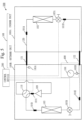
- Fig. 1 is a configuration diagram of the refrigerant leak determination apparatus 300 of Embodiment 1. A configuration of the refrigerant leak determination apparatus 300 will be described with reference to Fig. 1 .
- the refrigerant leak determination apparatus 300 is provided with the refrigeration cycle device 100 and a control device 200.
- the refrigeration cycle device 100 is configured with an indoor unit 100A and an outdoor unit 100B.
- Fig. 1 illustrates a configuration of a refrigerant circuit 120 of the refrigeration cycle device 100, and installation positions of a temperature sensor 101and a pressure sensor 104, which are detection means.
- the refrigeration cycle device 100 includes the refrigerant circuit 120 in which a compressor 109, a condenser, expansion valves 107A and 107B, and an evaporator are connected.
- the refrigeration cycle device 100 performs a refrigeration cycle in which a refrigerant circulates through the refrigerant circuit 120.
- an indoor heat exchanger 102 functions as the evaporator during cooling operation and functions as the condenser during heating operation.
- An outdoor heat exchanger 103 functions as the condenser during the cooling operation and functions as the evaporator during the heating operation.
- the compressor 109 In the refrigeration cycle device 100, the compressor 109, a four-way valve 110, the outdoor heat exchanger 103, the expansion valve 107B, the expansion valve 107A, and the indoor heat exchanger 102 are connected with pipes, and form the refrigerant circuit 120 in which the refrigerant circulates.
- a plurality of temperature sensors 101 are installed in the refrigerant circuit 120.
- connection devices 105A and 105B to be described below are installed in the refrigerant circuit 120.
- the indoor unit 100A includes a temperature sensor 101A, the indoor heat exchanger 102, the expansion valve 107A, and a temperature sensor 101B, in the refrigerant circuit 120.
- the outdoor unit 100B includes the connection device 105A, the compressor 109, a temperature sensor 101C, the four-way valve 110, a temperature sensor 101D, the outdoor heat exchanger 103, the expansion valve 107B, a temperature sensor 101E, the connection device 105B, and the pressure sensor 104, in the refrigerant circuit 120.
- the temperature sensors 101A to 101E measure a temperature of the refrigerant in the refrigerant circuit 120. Since the temperature sensors 101A to 101E have the same function, the temperature sensors 101A to 101E may be referred to as the temperature sensor 101 when there is no need to distinguish between them.
- the temperature sensor 101 is preferably a thermistor. Further, the temperature sensor 101 is preferably covered with a heat insulating material in order to prevent the temperature sensor 101 from being affected by outside air temperature. As a measurement principle, as temperature rises, a resistance value of the thermistor decreases by a constant value. The temperature can be detected by measuring the resistance value.
- the indoor heat exchanger 102 functions as the evaporator during the cooling operation by the refrigeration cycle device 100, and functions as the condenser during the heating operation by the refrigeration cycle device 100.
- outdoor heat exchanger 103 outdoor air exchanges heat with the refrigerant that passes through the outdoor heat exchanger 103.
- the outdoor heat exchanger 103 functions as the condenser during the cooling operation by the refrigeration cycle device 100, and functions as the evaporator during the heating operation by the refrigeration cycle device 100.
- the pressure sensor 104 measures a refrigerant pressure.
- a pressure reduction due to a reduction in solubility of refrigerator oil (hereinafter referred to as oil) is about several tens of kPa.
- oil refrigerator oil
- many of pressure gauges for conventional gauge manifolds have a pressure range of 0 kPa to 5 MPa, and a resolution of about 100 KPa. Therefore, the pressure reduction of several tens of kPa cannot be detected.
- the pressure sensor 104 it is preferable to use the fine pressure sensor that maintains a resolution of 5 to 10 kPa.
- the pressure sensor 104 has a resolution in a range from 5 kPa inclusive to 10 kPa inclusive.
- connection device 105A and the connection device 105B has a communication opening to an internal space of the refrigerant circuit 120, and is connected to the pressure sensor 104 that measures the refrigerant pressure in the internal space.
- connection device 105A and the connection device 105B is a pressure sensor connecting opening to which the pressure sensor 104 is connected. Since the connection device 105A and the connection device 105B have the same function, the connection device 105A and the connection device 105B is referred to as a connection device 105 when there is no need to distinguish between them.
- the connection device 105 communicates with the inside of the refrigerant circuit.
- the connection device 105 is preferably, for example, a service port. Pressure measurement is performed in a pressure equalization state in which the refrigeration cycle device 100 is suspended. Therefore, there is no consideration on a position of the connection device 105, which is the service port to which the pressure sensor 104 is connected. Either of the connection devices 105 is used in the pressure equalization state.
- Each of the expansion valve 107A and the expansion valve 107B is an electronic expansion valve. Since the expansion valve 107A and the expansion valve 107B have the same function, it is referred to as an expansion valve 107 when there is no need to distinguish between them.
- the expansion valve 107 is controlled by the control device 200, and efficiently controls an amount of refrigerant flow.
- each of the expansion valve 107A and the expansion valve 107B is opened at a certain opening degree, and flows into a gas pipe 121, a gas-liquid two-phase refrigerant that includes a liquid refrigerant. By flowing the liquid refrigerant into the gas pipe 121, the oil is recovered inside the compressor 109 together with the liquid refrigerant.
- the indoor unit 100A is assumed to be a refrigerator. That is, the cooling operation in which the indoor heat exchanger 102 functions as the evaporator is normal operation. In the cooling operation, a gas refrigerant flows out from the indoor heat exchanger 102 which is the evaporator, and the outflowed gas refrigerant flows into the compressor 109 via the gas pipe 121 and the four-way valve 110. During the cooling operation, the liquid refrigerant flows through a liquid pipe 122 illustrated below the gas pipe 121, from the outdoor unit 100B to the indoor unit 100A.
- the compressor 109 circulates the refrigerant in the refrigerant circuit 120 by increasing the pressure of the refrigerant.
- the four-way valve 110 is a value that switches the refrigeration cycle device 100 between the cooling operation and the heating operation.
- Fig. 1 illustrates a time of the cooling operation in which the indoor heat exchanger 102 functions as the evaporator.
- a case where the indoor heat exchanger 102 functions as the condenser is a time of the heating operation.
- Fig. 2 illustrates a functional block of the control device 200.
- Fig. 3 illustrates a hardware configuration of the control device 200. First, Fig. 2 will be described.
- the control device 200 is provided with an operation control unit 211, a leak determination unit 212, and a storage unit 213.
- the operation control unit 211 causes the refrigeration cycle device 100 to perform the oil recovery operation in which the oil inside the refrigerant circuit 120 is collected in the compressor.
- the leak determination unit 212 which is a determination unit, determines whether or not the refrigerant leaks from the refrigerant circuit 120, by comparing a reference pressure P1 which is a subject to comparison, with a refrigerant pressure P2 measured by the pressure sensor 104 after the oil recovery operation. A specific description will be given below.
- the operation control unit 211 controls operation of the refrigeration cycle device 100.
- the operation control unit 211 controls the expansion valves 107A and 107B, the compressor 109, and the four-way valve 110 of the refrigeration cycle device 100.
- the operation control unit 211 controls, for example, the opening degrees of the expansion valves 107A and 107B.
- the operation control unit 211 obtains a suspension signal to suspend the refrigeration cycle device 100.
- the operation control unit 211 obtains the number of rotations of the compressor 109, as the suspension signal. Suspension in the suspension signal is a state in which the compressor 109 suspends and the refrigerant does not circulate through the refrigerant circuit 120.
- the storage unit 213 stores various data such as the actual measured value P2 measured by the pressure sensor 104 and the saturation pressure P1 to be described below.
- the leak determination unit 212 obtains from the temperature sensor 101 and the pressure sensor 104, measurement data on the temperature sensor 101 and the pressure sensor 104, and stores the obtained measurement data into the storage unit 213.
- the leak determination unit 212 extracts the lowest temperature data from among pieces of temperature data obtained by the temperature sensor 101.
- the leak determination unit 212 calculates the saturation pressure P1 from the lowest temperature among the pieces of temperature data obtained by the temperature sensor 101.
- the leak determination unit 212 calculates a difference P1-P2 between the saturation pressure P1 and the pressure value P2 measured by the pressure sensor 104. When the difference between the saturation pressure P1 and the pressure value P2 is greater than a resolution of a differential pressure gauge, the leak determination unit 212 determines that there is a leak.
- the leak determination unit 212 determines that there is no leak.
- the resolution is assumed to be 5 kPa.
- the leak determination unit 212 notifies a user or a worker of refrigerant leak abnormality.
- the control device 200 is a computer.
- the control device 200 is provided with a processor 210.
- the control device 200 is provided with, in addition to the processor 210, other pieces of hardware such as a main storage device 220, an auxiliary storage device 230, an input IF 240, an output IF 250, and a communication IF 260.
- IF is an abbreviation for interface.
- the processor 210 is connected to the other pieces of hardware via a signal line 270, and controls the other pieces of hardware.
- the control device 200 is provided with the operation control unit 211 and the leak determination unit 212, as functional components. Functions of the operation control unit 211 and the leak determination unit 212 are implemented by a refrigerant leak determination program 201.
- the processor 210 is a device that executes the refrigerant leak determination program 201.
- the refrigerant leak determination program 201 is a program that implements the functions of the operation control unit 211 and the leak determination unit 212.
- the processor 210 is an Integrated Circuit (IC) that performs arithmetic processing.
- IC Integrated Circuit
- a specific example of the processor 210 is a Central Processing Unit (CPU), a Digital Signal Processor (DSP), or a Graphics Processing Unit (GPU).
- a specific example of the main storage device 220 is a Static Random Access Memory (SRAM), or a Dynamic Random Access Memory (DRAM).
- SRAM Static Random Access Memory
- DRAM Dynamic Random Access Memory
- the auxiliary storage device 230 is a storage device that stores data in a nonvolatile manner.
- a specific example of the auxiliary storage device 230 is a Hard Disk Drive (HDD).
- the auxiliary storage device 230 may be a portable recording medium such as a Secure Digital(SD) (registered trademark) memory card, a NAND flash, a flexible disk, an optical disc, a compact disc, a Blu-ray (registered trademark) disc, or a Digital Versatile Disk (DVD).
- SD Secure Digital
- NAND flash NAND flash
- the auxiliary storage device 230 implements the storage unit 213.
- the auxiliary storage device 230 stores the refrigerant leak determination program 201.
- the input IF 240 is a port to which data is input from each device.
- the input IF 240 is connected to the temperature sensor 101 and the pressure sensor 104.
- the output IF 250 is a port to which each of various devices is connected, and from which data is output by the processor 210 to the each of various devices.
- the output IF 250 is connected to a notification device 500.
- the communication IF 260 is a communication port for the processor 210 to communicate with other devices.
- the communication IF 260 is connected to the compressor 109, the four-way valve 110, and the expansion valves 107A and 107B.
- the processor 210 loads the refrigerant leak determination program 201 from the auxiliary storage device 230 to the main storage device 220, reads the refrigerant leak determination program 201 from the main storage device 220, and executes the refrigerant leak determination program 201.
- the main storage device 220 stores not only the refrigerant leak determination program 201 but also an Operating System (OS).
- the processor 210 executes the refrigerant leak determination program 201 while executing the OS.
- the control device 200 may be provided with a plurality of processors in place of the processor 210. The plurality of processors share execution of the refrigerant leak determination program 201. Each of the plurality of processors is, like the processor 210, a device that executes the refrigerant leak determination program 201.
- Data, information, a signal value, and a variable value that are used, processed, or output by the refrigerant leak determination program 201 are stored in the main storage device 220, the auxiliary storage device 230, or stored in a register or a cache memory in the processor 210.
- the refrigerant leak determination program 201 is a program that causes the computer to execute each process, each procedure, or each step, where "unit" in each of the operation control unit 211 and the leak determination unit 212 is interpreted as "process", "procedure”, or "step”.
- a refrigerant leak determination method is a method to be performed by the control device 200 which is the computer, executing the refrigerant leak determination program 201.
- the refrigerant leak determination program 201 may be provided as being stored in a computer readable recording medium or may be provided as a program product.
- Fig. 4 is a flowchart illustrating operation of the refrigerant leak determination apparatus 300.
- the operation of the refrigerant leak determination apparatus 300 will be described with reference to Fig. 4 .
- An operation procedure of the control device 200 in the refrigerant leak determination apparatus 300 is equivalent to a control method.
- a program that implements operation of the control device 200 is equivalent to the refrigerant leak determination program 201.
- step S300 the operation control unit 211 receives as the number of rotations of the compressor 109 of the refrigeration cycle device 100, the suspension signal of the cooling operation or the heating operation of the refrigeration cycle device 100.
- Fig. 1 illustrates the state of the cooling operation.
- the operation control unit 211 opens the expansion valve 107A and the expansion valve 107B, and shifts a heating operation mode or a cooing operation mode to an oil recovery operation mode.
- the operation control unit 211 causes the refrigeration cycle device 100 to perform operation in a mode different from the oil recovery operation
- the operation control unit 211 causes the refrigeration cycle device 100 to continue to perform the oil recovery operation from the mode different from the oil recovery operation, and to suspend the operation of the refrigeration cycle device 100 after the oil recovery operation is performed.
- step S301 the operation control unit 211 opens the expansion valves 107A and 107B, and starts the oil recovery operation.
- the oil recovery operation will be described.
- some of oil inside the compressor 109 flow out from the compressor 109 slightly, together with the gas refrigerant.
- a large amount of oil that has flowed out from the compressor 109 especially stay between an outlet of the indoor heat exchanger 102 which is the evaporator and a suction opening of the compressor 109. That is, during the cooling operation, the large amount of oil stay in the gas pipe 121.
- the gas refrigerant flows out from the outlet of the indoor heat exchanger 102 which is the evaporator.
- the operation control unit 211 controls the opening degrees of the expansion valves 107A and 107B, so that the gas-liquid two-phase refrigerant flows out from the indoor heat exchanger 102.
- the liquid refrigerant of the gas-liquid two-phase refrigerant recovers the oil to the compressor 109 with shearing force like dragging the oil inside the gas pipe 121.
- the liquid refrigerant also flows into the compressor 109, but its amount is small. Therefore, there is no problem such as failure in the compressor 109.
- the oil is recovered to the compressor 109 by the oil recovery operation, and a trouble such as poor lubrication of the compressor 109 is avoided.
- the operation control unit 211 recovers the oil inside the refrigerant circuit 120 by the oil recovery operation, to the compressor 109 installed inside the outdoor unit 100B.
- the operation control unit 211 controls the opening degrees of the expansion valves during the oil recovery operation, so that the liquid refrigerant flows through a pipe in an area where the refrigerant flows from the evaporator to the compressor, and a pipe in an area where the refrigerant flows from the compressor to the condenser, in the refrigerant circuit 120.
- a specific description will be given below.
- the operation control unit 211 performs oil recovery by widening the opening degrees of the expansion valves 107A and 107B, increasing an inverter frequency of the compressor 109, and increasing a supply amount of the liquid refrigerant into the gas pipe.
- the operation control unit 211 ends the oil recovery operation after ten minutes pass from start of the oil recovery operation.
- step S302 when ten minutes have passed from the start of the oil recovery operation, the operation control unit 211 suspends the oil recovery operation. That is, the operation control unit 211 suspends operation of the compressor 109, and suspends the operation of the refrigeration cycle device 100.
- step S303 the leak determination unit 212 measures the temperature by the temperature sensor 101 installed in the refrigerant circuit 120, and stores the measured temperature in the storage unit 213.
- step S304 the leak determination unit 212 determines whether or not the temperature measured in the refrigerant circuit 120 is stable.
- the leak determination unit 212 determines that, for example, the temperature is stable when the temperature of the refrigerant circuit 120 is periodically measured, and a temperature change value is less than or equal to ⁇ 0.5 °C.
- step S305 the leak determination unit 212 extracts the lowest measured value in the refrigerant circuit 120 from among pieces of measured temperature data, and stores the lowest measured value in the storage unit 213.
- the refrigeration cycle device 100 is provided with the temperature sensor 101 that measures the refrigerant temperature of the refrigerant circuit 120.
- the leak determination unit 212 which is the determination unit, calculates from the refrigerant temperature measured by the temperature sensor 101, the saturation pressure of the refrigerant, and uses the calculated saturation pressure as the reference pressure P1. A specific description will be given below.
- step S306 the leak determination unit 212 calculates the saturation pressure P1 using the lowest temperature stored in step S305, and stores the calculated saturation pressure P1 in the storage unit 213.
- the saturation pressure P1 is a function of the temperature t.
- the leak determination unit 212 calculates P1(tmin) of the measured lowest temperature tmin, using P1(t).
- a formula of P1(t) is stored in the auxiliary storage device 230.
- step S307 the pressure sensor 104 is connected to the connection device 105 by a maintenance worker.
- the pressure sensor 104 may be connected to either the connection device 105A or the connection device 105B.
- the leak determination unit 212 which is the determination unit, uses the measured value of the pressure sensor 104 at the suspended state of the refrigeration cycle device 100 after the oil recovery operation is performed. A specific description will be given below.
- step S308 the leak determination unit 212 obtains from the pressure sensor 104, the reiterant pressure P2 when at the operation suspended state of the refrigeration cycle device 100.
- the leak determination unit 212 stores the measured value P2 into the storage unit 213.
- step S309 the leak determination unit 212 calculates P1-P2 which is the difference between the saturation pressure P1 measured in step S306 and the measured pressure P2 obtained in step S308.
- the leak determination unit 212 determines whether or not the difference is greater than the resolution of the pressure sensor 104.
- the resolution is assumed to be 5 kPa.
- the leak determination unit 212 determines in step S310 that "there is refrigerant leak".
- the leak determination unit 212 determines if the state in which the difference in the pressure is less than or equal to the resolution has passed for one or more hours from the start of the measurement by the pressure sensor 104 (step S311).
- steps S308, S309, and S311 are repeated.
- the leak determination unit 212 determines that "there is no refrigerant leak" in step S312.
- step S313 the leak determination unit 212 issues a notification of a result of step S310 or step S312 by the notification device 500.
- the refrigerant leak determination apparatus 300 has been described above.
- the operation of the refrigerant leak determination apparatus 300 can be grasped as a refrigerant leak determination method as follows:
- the leak determination unit 212 treats the measurement data of the only one temperature sensor 101 as the lowest temperature.
- Modification 1 of the refrigerant leak determination apparatus 300 of Embodiment 1 will be described with reference to Figs. 5 and 6 .
- Modification 1 it is assumed to have the refrigeration cycle device 100 in which the pressure in the refrigerant circuit 120 differs between the indoor unit 100A side and the outdoor unit 100B side when the operation of the refrigeration cycle device 100 is suspended.
- the pressure is separated between the outdoor unit 100B side and the indoor unit 100A side, by pump-down operation, and the pressure differs between a high-pressure side and a low-pressure side.
- the pressure is measured on the indoor unit 100A side, it may be determined that the pressure reduction that exceeds the resolution is undetected. Therefore, a position for measuring the pressure is limited to the outdoor unit 100B side.
- Fig. 5 illustrates a configuration of the refrigerant leak determination apparatus 300 of the embodiment.
- a configuration of a refrigerant circuit of the refrigeration cycle device 100, and installation positions of the temperature sensor 101 and the pressure sensor 104, in the refrigerant leak determination apparatus 300 of Modification 1 are basically the same as those in the refrigerant leak determination apparatus 300 of Embodiment 1.
- the configuration of Fig. 5 is the same as the configuration of Fig. 1 .
- the connection device 105 to which a pressure sensor 404 is to be connected is limited to the connection device 105B installed at a connecting opening to the inside of a system on the outdoor unit 100B side. In Fig. 5 , this matter is cleanly indicated by enclosing the connection device 105B using a frame 400 of a dashed line.
- Fig. 6 is a flowchart illustrating operation of the refrigerant leak determination apparatus 300 of Modification 1.
- the operation of the refrigerant leak determination apparatus 300 of Modification 1 will be described with reference to Fig. 6 .
- the flowchart of Fig. 6 differs from the flowchart of Fig. 4 of Embodiment 1 in that step S301A is added, and in the content of step S307. Since other steps are the same as those in Fig. 4 , a description thereof will be omitted.
- the refrigeration cycle device 100 of the modification requires the pump-down operation before the operation is suspended.
- the connection device 105B to which the pressure sensor 104 is connected communicates with the inside of a system of the outdoor heat exchanger 103 that functions as the condenser. A specific description will be given below.
- step S301A the operation control unit 211 performs the pump-down operation, and recovers the liquid refrigerant to the compressor 109 installed inside the outdoor unit 100B.
- the operation control unit 211 fully opens the expansion valves 107A and 107B, performs forced cooling operation, and recovers the liquid refrigerant to the compressor 109. After a certain period of time passes from the start of the operation, processing ends.
- step S302 after the pump-down operation is completed, the operation control unit 211 suspends the operation of the refrigeration cycle device 100.
- step S307 a maintenance worker connects the pressure sensor 404 to the connection device 105B that communicates with the inside of the system on the outdoor unit 100B side. Steps after step S307 are the same as those in Fig. 4 .
- the pressure sensor 104 when connecting to a model that performs the pump-down operation before the operation of the refrigeration cycle device 100 is suspended, the pressure sensor 104 is connected to a connection device that communicates with the inside of the system on the outdoor unit 100B side.
- Fig. 7 is a flowchart illustrating operation of the refrigerant leak determination apparatus 300 of Modification 2. Modification 2 will be described with reference to Fig. 7 .
- the configuration of the refrigerant leak determination apparatus 300 is the same as that in Embodiment 1. That is, the refrigeration cycle device 100 and the control device 200 are the same as those in Embodiment 1.
- the flowchart of Fig. 7 differs from the flowchart of Fig. 7 in that there are no steps S305 and S306, and in the content of step S309. Other than these, Fig. 7 is the same as Fig. 4 . This is because the refrigerant pressure at suspension time in the refrigerant circuit 120 at time of factory shipment is used in place of the saturation pressure P1 as follows.
- a refrigeration leak may be detected from a pressure difference between a refrigerant pressure at suspension time in the refrigerant circuit 120 of the refrigeration cycle device 100 at the time of factory shipment, and a refrigerant pressure measured by a pressure sensor 1004.
- the refrigerant pressure at the suspension time at the time of factory shipment is stored in the auxiliary storage device 230. This pressure is referred to as P1.
- step S309 will be described, and a description of other steps will be omitted.
- the leak determination unit 212 which is the determination unit, uses as the reference pressure P1, the refrigerant pressure retained in advance at the time of factory shipment. A specific description will be given below.
- step S309 the leak determination unit 212 calculates the difference (P1-P2) between the pressure P1 at the time of factory shipment stored in the auxiliary storage device 230 and the pressure P2 obtained in step S308. Steps after step S309 are the same as those in Fig. 4 .
- Modification 2 it is possible to omit step S305 in which the lowest temperature sensor value in the refrigerant circuit 120 is extracted, and step S306 in which the saturation pressure is calculated. Therefore, Modification 2 can determine a refrigerant leak faster than usual.
- Embodiment 1 that includes Modification 1 and Modification 2 has been described above. Two or more technical matters of these embodiments may be combined for implementation. Alternatively, one technical matter of Embodiment 1 may be partially implemented.
- 100 refrigeration cycle device; 100A: indoor unit; 100B: outdoor unit; 101A, 101B, 101C, 101D, 101E: temperature sensor; 102: indoor heat exchanger; 103: outdoor heat exchanger; 104: pressure sensor; 105A, 105B: connection device; 107A, 107B: expansion valve; 109: compressor; 110: four-way valve; 120: refrigerant circuit; 121: gas pipe; 122: liquid pipe; 200: control device; 201: refrigerant leak determination program; 210: processor; 211: operation control unit; 212: leak determination unit; 213: storage unit; 220: main storage device; 230: auxiliary storage device; 240: input IF; 250: output IF; 260: communication IF; 270: signal line; 300: refrigerant leak determination apparatus; 400: frame; 500: notification device.
Landscapes
- Engineering & Computer Science (AREA)
- Physics & Mathematics (AREA)
- Mechanical Engineering (AREA)
- Thermal Sciences (AREA)
- General Engineering & Computer Science (AREA)
- Air Conditioning Control Device (AREA)
Abstract
Description
- The present disclosure relates to a refrigerant leak determination apparatus, a control device, a refrigerant leak determination program, and a refrigerant leak determination method.
- Conventionally, there is a technique to diagnose based on a pressure reduction, presence or absence of a refrigerant leak in a refrigeration device, by comparing a vapor-liquid equilibrium pressure to be calculated from a measured ambient temperature with a pressure measured using a pressure detection means (for example, Patent Literature 1).
- Patent Literature 1:
JP H04-225769 A - When the method of
Patent Literature 1 is used to detect a refrigerant leak in a refrigeration device during suspension of operation, for example, a distribution of oil for a refrigerator in a refrigerant circuit differs depending on an installation environment of the refrigerator. An amount of the oil and an environmental temperature affect an amount of a refrigerant to be dissolved in the oil. Therefore, depending on a situation of the distribution of the oil for the refrigerator, there is a risk that an amount of pressure reduction to be detected may be uncertain, the amount of pressure reduction being a basis for determining the refrigerant leak. Accordingly, with the method of diagnosing the refrigerant leak disclosed inPatent Literature 1, depending on the distribution of the oil in the refrigeration device, there is a risk that dispersion of measured pressure occurs, and a measurement error in a pressure occurs. - The present disclosure aims to reduce a measurement error in measured pressure.
- A refrigerant leak determination apparatus according to the present disclosure includes:
- a refrigeration cycle device that includes a refrigerant circuit in which a compressor, a condenser, an expansion valve and an evaporator are connected, and that performs a refrigeration cycle in which a refrigerant circulates through the refrigerant circuit;
- a connection device that includes a communication opening to an internal space of the refrigerant circuit, and that is connected to a pressure sensor that measures a refrigerant pressure in the internal space; and
- a control device including:
- an operation control unit that causes the refrigeration cycle device to perform oil recovery operation to collect oil inside the refrigerant circuit in the compressor; and
- a determination unit to determine a leak of the refrigerant from the refrigerant circuit, by comparing a reference pressure for comparison, with the refrigerant pressure measured by the pressure sensor after the oil recovery operation.
- In a refrigerant leak determination apparatus according to the present disclosure, a control device causes a refrigeration cycle device to perform oil recovery operation. After the oil recovery operation, a pressure of a refrigerant is measured. Accordingly, it is possible to suppress dispersion of the measured pressure, and to detect a refrigerant leak more reliable than before.
-
-
Fig. 1 is a diagram ofEmbodiment 1 and a configuration diagram of a refrigerantleak determination apparatus 300. -
Fig. 2 is a diagram ofEmbodiment 1 and a block configuration diagram of acontrol device 200. -
Fig. 3 is a diagram ofEmbodiment 1 and a hardware configuration diagram of thecontrol device 200. -
Fig. 4 is a diagram ofEmbodiment 1 and a flowchart illustrating operation of the refrigerantleak determination apparatus 300. -
Fig. 5 is a diagram ofEmbodiment 1 and a configuration diagram of the refrigerantleak determination apparatus 300 ofModification 1. -
Fig. 6 is a diagram ofEmbodiment 1 and a lowchart illustrating operation ofModification 1. -
Fig. 7 is a diagram ofEmbodiment 1 and a lowchart illustrating operation of Modification 2. - In the description and drawings of embodiments, the same or equivalent portions are denoted by the same reference sign. A description of a portion denoted by the same reference sign will be suitably omitted or simplified. In the following embodiments, "unit" may be interpreted as "circuit", "step", "procedure", "process", or "circuitry", as necessary.
- A
refrigeration cycle device 100 illustrated throughFigs. 1 to 4 is assumed to be therefrigeration cycle device 100 in which pressure in a refrigerant circuit is equalized during suspension of operation. InFigs. 5 and6 ofModification 1, therefrigeration cycle device 100 is assumed to be therefrigeration cycle device 100 in which pressure in the refrigerant circuit is not equalized during suspension of operation. Further, while a refrigerantleak determination apparatus 300 illustrated throughFigs. 1 to 4 and the refrigerantleak determination apparatus 300 ofModification 1 calculate saturation pressure, Modification 2 indicates a configuration where the saturation pressure is not calculated. -
Fig. 1 is a configuration diagram of the refrigerantleak determination apparatus 300 ofEmbodiment 1. A configuration of the refrigerantleak determination apparatus 300 will be described with reference toFig. 1 . The refrigerantleak determination apparatus 300 is provided with therefrigeration cycle device 100 and acontrol device 200. Therefrigeration cycle device 100 is configured with anindoor unit 100A and anoutdoor unit 100B.Fig. 1 illustrates a configuration of arefrigerant circuit 120 of therefrigeration cycle device 100, and installation positions of a temperature sensor 101and apressure sensor 104, which are detection means. - The
refrigeration cycle device 100 includes therefrigerant circuit 120 in which acompressor 109, a condenser,expansion valves refrigeration cycle device 100 performs a refrigeration cycle in which a refrigerant circulates through therefrigerant circuit 120. As described below, anindoor heat exchanger 102 functions as the evaporator during cooling operation and functions as the condenser during heating operation. Anoutdoor heat exchanger 103 functions as the condenser during the cooling operation and functions as the evaporator during the heating operation. - In the
refrigeration cycle device 100, thecompressor 109, a four-way valve 110, theoutdoor heat exchanger 103, theexpansion valve 107B, theexpansion valve 107A, and theindoor heat exchanger 102 are connected with pipes, and form therefrigerant circuit 120 in which the refrigerant circulates. A plurality oftemperature sensors 101 are installed in therefrigerant circuit 120. Further,connection devices refrigerant circuit 120. - The
indoor unit 100A includes atemperature sensor 101A, theindoor heat exchanger 102, theexpansion valve 107A, and atemperature sensor 101B, in therefrigerant circuit 120. - The
outdoor unit 100B includes theconnection device 105A, thecompressor 109, a temperature sensor 101C, the four-way valve 110, atemperature sensor 101D, theoutdoor heat exchanger 103, theexpansion valve 107B, atemperature sensor 101E, theconnection device 105B, and thepressure sensor 104, in therefrigerant circuit 120. - The
temperature sensors 101A to 101E measure a temperature of the refrigerant in therefrigerant circuit 120. Since thetemperature sensors 101A to 101E have the same function, thetemperature sensors 101A to 101E may be referred to as thetemperature sensor 101 when there is no need to distinguish between them. Thetemperature sensor 101 is preferably a thermistor. Further, thetemperature sensor 101 is preferably covered with a heat insulating material in order to prevent thetemperature sensor 101 from being affected by outside air temperature. As a measurement principle, as temperature rises, a resistance value of the thermistor decreases by a constant value. The temperature can be detected by measuring the resistance value. - In the
indoor heat exchanger 102, indoor air exchanges heat with the refrigerant that passes through theindoor heat exchanger 102. Theindoor heat exchanger 102 functions as the evaporator during the cooling operation by therefrigeration cycle device 100, and functions as the condenser during the heating operation by therefrigeration cycle device 100. - In the
outdoor heat exchanger 103, outdoor air exchanges heat with the refrigerant that passes through theoutdoor heat exchanger 103. By switching the four-way valve 110, theoutdoor heat exchanger 103 functions as the condenser during the cooling operation by therefrigeration cycle device 100, and functions as the evaporator during the heating operation by therefrigeration cycle device 100. - The
pressure sensor 104 measures a refrigerant pressure. As thepressure sensor 104, it is preferable to use a fine pressure sensor. It is assumed that a pressure reduction due to a reduction in solubility of refrigerator oil (hereinafter referred to as oil) is about several tens of kPa. Accordingly, many of pressure gauges for conventional gauge manifolds have a pressure range of 0 kPa to 5 MPa, and a resolution of about 100 KPa. Therefore, the pressure reduction of several tens of kPa cannot be detected. Accordingly, as thepressure sensor 104, it is preferable to use the fine pressure sensor that maintains a resolution of 5 to 10 kPa. InEmbodiment 1, thepressure sensor 104 has a resolution in a range from 5 kPa inclusive to 10 kPa inclusive. - Each of the
connection device 105A and theconnection device 105B has a communication opening to an internal space of therefrigerant circuit 120, and is connected to thepressure sensor 104 that measures the refrigerant pressure in the internal space. - Each of the
connection device 105A and theconnection device 105B is a pressure sensor connecting opening to which thepressure sensor 104 is connected. Since theconnection device 105A and theconnection device 105B have the same function, theconnection device 105A and theconnection device 105B is referred to as a connection device 105 when there is no need to distinguish between them. The connection device 105 communicates with the inside of the refrigerant circuit. The connection device 105 is preferably, for example, a service port. Pressure measurement is performed in a pressure equalization state in which therefrigeration cycle device 100 is suspended. Therefore, there is no consideration on a position of the connection device 105, which is the service port to which thepressure sensor 104 is connected. Either of the connection devices 105 is used in the pressure equalization state. - Each of the
expansion valve 107A and theexpansion valve 107B is an electronic expansion valve. Since theexpansion valve 107A and theexpansion valve 107B have the same function, it is referred to as an expansion valve 107 when there is no need to distinguish between them. The expansion valve 107 is controlled by thecontrol device 200, and efficiently controls an amount of refrigerant flow. During oil recovery operation to be described below, each of theexpansion valve 107A and theexpansion valve 107B is opened at a certain opening degree, and flows into agas pipe 121, a gas-liquid two-phase refrigerant that includes a liquid refrigerant. By flowing the liquid refrigerant into thegas pipe 121, the oil is recovered inside thecompressor 109 together with the liquid refrigerant. - The gas pipe will be described. The oil recovery operation will be described below in step S301. In
Embodiment 1, theindoor unit 100A is assumed to be a refrigerator. That is, the cooling operation in which theindoor heat exchanger 102 functions as the evaporator is normal operation. In the cooling operation, a gas refrigerant flows out from theindoor heat exchanger 102 which is the evaporator, and the outflowed gas refrigerant flows into thecompressor 109 via thegas pipe 121 and the four-way valve 110. During the cooling operation, the liquid refrigerant flows through aliquid pipe 122 illustrated below thegas pipe 121, from theoutdoor unit 100B to theindoor unit 100A. - The
compressor 109 circulates the refrigerant in therefrigerant circuit 120 by increasing the pressure of the refrigerant. - The four-
way valve 110 is a value that switches therefrigeration cycle device 100 between the cooling operation and the heating operation.Fig. 1 illustrates a time of the cooling operation in which theindoor heat exchanger 102 functions as the evaporator. A case where theindoor heat exchanger 102 functions as the condenser is a time of the heating operation. -
Fig. 2 illustrates a functional block of thecontrol device 200.Fig. 3 illustrates a hardware configuration of thecontrol device 200. First,Fig. 2 will be described. Thecontrol device 200 is provided with anoperation control unit 211, aleak determination unit 212, and astorage unit 213. - The
operation control unit 211 causes therefrigeration cycle device 100 to perform the oil recovery operation in which the oil inside therefrigerant circuit 120 is collected in the compressor. Theleak determination unit 212 which is a determination unit, determines whether or not the refrigerant leaks from therefrigerant circuit 120, by comparing a reference pressure P1 which is a subject to comparison, with a refrigerant pressure P2 measured by thepressure sensor 104 after the oil recovery operation. A specific description will be given below. - The
operation control unit 211 controls operation of therefrigeration cycle device 100. Theoperation control unit 211 controls theexpansion valves compressor 109, and the four-way valve 110 of therefrigeration cycle device 100. Theoperation control unit 211 controls, for example, the opening degrees of theexpansion valves operation control unit 211 obtains a suspension signal to suspend therefrigeration cycle device 100. Theoperation control unit 211 obtains the number of rotations of thecompressor 109, as the suspension signal. Suspension in the suspension signal is a state in which thecompressor 109 suspends and the refrigerant does not circulate through therefrigerant circuit 120. - The
storage unit 213 stores various data such as the actual measured value P2 measured by thepressure sensor 104 and the saturation pressure P1 to be described below. - The
leak determination unit 212 obtains from thetemperature sensor 101 and thepressure sensor 104, measurement data on thetemperature sensor 101 and thepressure sensor 104, and stores the obtained measurement data into thestorage unit 213. Theleak determination unit 212 extracts the lowest temperature data from among pieces of temperature data obtained by thetemperature sensor 101. Theleak determination unit 212 calculates the saturation pressure P1 from the lowest temperature among the pieces of temperature data obtained by thetemperature sensor 101. Theleak determination unit 212 calculates a difference P1-P2 between the saturation pressure P1 and the pressure value P2 measured by thepressure sensor 104. When the difference between the saturation pressure P1 and the pressure value P2 is greater than a resolution of a differential pressure gauge, theleak determination unit 212 determines that there is a leak. When the difference between the saturation pressure P1 and the pressure value P2 is smaller than the resolution of the differential pressure gauge, theleak determination unit 212 determines that there is no leak. InEmbodiment 1, the resolution is assumed to be 5 kPa. Theleak determination unit 212 notifies a user or a worker of refrigerant leak abnormality. - The hardware configuration of the
control device 200 will be described with reference toFig. 3 . Thecontrol device 200 is a computer. Thecontrol device 200 is provided with aprocessor 210. Thecontrol device 200 is provided with, in addition to theprocessor 210, other pieces of hardware such as amain storage device 220, anauxiliary storage device 230, an input IF 240, an output IF 250, and a communication IF 260. IF is an abbreviation for interface. Theprocessor 210 is connected to the other pieces of hardware via asignal line 270, and controls the other pieces of hardware. - The
control device 200 is provided with theoperation control unit 211 and theleak determination unit 212, as functional components. Functions of theoperation control unit 211 and theleak determination unit 212 are implemented by a refrigerantleak determination program 201. - The
processor 210 is a device that executes the refrigerantleak determination program 201. The refrigerantleak determination program 201 is a program that implements the functions of theoperation control unit 211 and theleak determination unit 212. Theprocessor 210 is an Integrated Circuit (IC) that performs arithmetic processing. A specific example of theprocessor 210 is a Central Processing Unit (CPU), a Digital Signal Processor (DSP), or a Graphics Processing Unit (GPU). - A specific example of the
main storage device 220 is a Static Random Access Memory (SRAM), or a Dynamic Random Access Memory (DRAM). Themain storage device 220 retains arithmetic results of theprocessor 210. - The
auxiliary storage device 230 is a storage device that stores data in a nonvolatile manner. A specific example of theauxiliary storage device 230 is a Hard Disk Drive (HDD). Alternatively, theauxiliary storage device 230 may be a portable recording medium such as a Secure Digital(SD) (registered trademark) memory card, a NAND flash, a flexible disk, an optical disc, a compact disc, a Blu-ray (registered trademark) disc, or a Digital Versatile Disk (DVD). Theauxiliary storage device 230 implements thestorage unit 213. Further, theauxiliary storage device 230 stores the refrigerantleak determination program 201. - The input IF 240 is a port to which data is input from each device. The input IF 240 is connected to the
temperature sensor 101 and thepressure sensor 104. The output IF 250 is a port to which each of various devices is connected, and from which data is output by theprocessor 210 to the each of various devices. The output IF 250 is connected to anotification device 500. The communication IF 260 is a communication port for theprocessor 210 to communicate with other devices. The communication IF 260 is connected to thecompressor 109, the four-way valve 110, and theexpansion valves - The
processor 210 loads the refrigerantleak determination program 201 from theauxiliary storage device 230 to themain storage device 220, reads the refrigerantleak determination program 201 from themain storage device 220, and executes the refrigerantleak determination program 201. Themain storage device 220 stores not only the refrigerantleak determination program 201 but also an Operating System (OS). Theprocessor 210 executes the refrigerantleak determination program 201 while executing the OS. Thecontrol device 200 may be provided with a plurality of processors in place of theprocessor 210. The plurality of processors share execution of the refrigerantleak determination program 201. Each of the plurality of processors is, like theprocessor 210, a device that executes the refrigerantleak determination program 201. Data, information, a signal value, and a variable value that are used, processed, or output by the refrigerantleak determination program 201 are stored in themain storage device 220, theauxiliary storage device 230, or stored in a register or a cache memory in theprocessor 210. - The refrigerant
leak determination program 201 is a program that causes the computer to execute each process, each procedure, or each step, where "unit" in each of theoperation control unit 211 and theleak determination unit 212 is interpreted as "process", "procedure", or "step". - Further, a refrigerant leak determination method is a method to be performed by the
control device 200 which is the computer, executing the refrigerantleak determination program 201. The refrigerantleak determination program 201 may be provided as being stored in a computer readable recording medium or may be provided as a program product. -
Fig. 4 is a flowchart illustrating operation of the refrigerantleak determination apparatus 300. The operation of the refrigerantleak determination apparatus 300 will be described with reference toFig. 4 . An operation procedure of thecontrol device 200 in the refrigerantleak determination apparatus 300 is equivalent to a control method. A program that implements operation of thecontrol device 200 is equivalent to the refrigerantleak determination program 201. - In step S300, the
operation control unit 211 receives as the number of rotations of thecompressor 109 of therefrigeration cycle device 100, the suspension signal of the cooling operation or the heating operation of therefrigeration cycle device 100.Fig. 1 illustrates the state of the cooling operation. After receiving the suspension signal, theoperation control unit 211 opens theexpansion valve 107A and theexpansion valve 107B, and shifts a heating operation mode or a cooing operation mode to an oil recovery operation mode. - When the
operation control unit 211 causes therefrigeration cycle device 100 to perform operation in a mode different from the oil recovery operation, theoperation control unit 211 causes therefrigeration cycle device 100 to continue to perform the oil recovery operation from the mode different from the oil recovery operation, and to suspend the operation of therefrigeration cycle device 100 after the oil recovery operation is performed. A specific description will be given below. - In step S301, the
operation control unit 211 opens theexpansion valves - Here, the oil recovery operation will be described. During the cooling operation, some of oil inside the
compressor 109 flow out from thecompressor 109 slightly, together with the gas refrigerant. A large amount of oil that has flowed out from thecompressor 109 especially stay between an outlet of theindoor heat exchanger 102 which is the evaporator and a suction opening of thecompressor 109. That is, during the cooling operation, the large amount of oil stay in thegas pipe 121. In the cooling operation, the gas refrigerant flows out from the outlet of theindoor heat exchanger 102 which is the evaporator. Therefore, in the oil recovery operation, theoperation control unit 211 controls the opening degrees of theexpansion valves indoor heat exchanger 102. The liquid refrigerant of the gas-liquid two-phase refrigerant recovers the oil to thecompressor 109 with shearing force like dragging the oil inside thegas pipe 121. The liquid refrigerant also flows into thecompressor 109, but its amount is small. Therefore, there is no problem such as failure in thecompressor 109. The oil is recovered to thecompressor 109 by the oil recovery operation, and a trouble such as poor lubrication of thecompressor 109 is avoided. - As described above, the
operation control unit 211 recovers the oil inside therefrigerant circuit 120 by the oil recovery operation, to thecompressor 109 installed inside theoutdoor unit 100B. Theoperation control unit 211 controls the opening degrees of the expansion valves during the oil recovery operation, so that the liquid refrigerant flows through a pipe in an area where the refrigerant flows from the evaporator to the compressor, and a pipe in an area where the refrigerant flows from the compressor to the condenser, in therefrigerant circuit 120. A specific description will be given below. - Specifically, the
operation control unit 211 performs oil recovery by widening the opening degrees of theexpansion valves compressor 109, and increasing a supply amount of the liquid refrigerant into the gas pipe. Theoperation control unit 211 ends the oil recovery operation after ten minutes pass from start of the oil recovery operation. - In step S302, when ten minutes have passed from the start of the oil recovery operation, the
operation control unit 211 suspends the oil recovery operation. That is, theoperation control unit 211 suspends operation of thecompressor 109, and suspends the operation of therefrigeration cycle device 100. - In step S303, the
leak determination unit 212 measures the temperature by thetemperature sensor 101 installed in therefrigerant circuit 120, and stores the measured temperature in thestorage unit 213. - In step S304, the
leak determination unit 212 determines whether or not the temperature measured in therefrigerant circuit 120 is stable. Theleak determination unit 212 determines that, for example, the temperature is stable when the temperature of therefrigerant circuit 120 is periodically measured, and a temperature change value is less than or equal to ± 0.5 °C. - In step S305, the
leak determination unit 212 extracts the lowest measured value in therefrigerant circuit 120 from among pieces of measured temperature data, and stores the lowest measured value in thestorage unit 213. - The
refrigeration cycle device 100 is provided with thetemperature sensor 101 that measures the refrigerant temperature of therefrigerant circuit 120. Theleak determination unit 212 which is the determination unit, calculates from the refrigerant temperature measured by thetemperature sensor 101, the saturation pressure of the refrigerant, and uses the calculated saturation pressure as the reference pressure P1. A specific description will be given below. - In step S306, the
leak determination unit 212 calculates the saturation pressure P1 using the lowest temperature stored in step S305, and stores the calculated saturation pressure P1 in thestorage unit 213. The saturation pressure P1 is a function of the temperature t. Theleak determination unit 212 calculates P1(tmin) of the measured lowest temperature tmin, using P1(t). A formula of P1(t) is stored in theauxiliary storage device 230. - In step S307, the
pressure sensor 104 is connected to the connection device 105 by a maintenance worker. Thepressure sensor 104 may be connected to either theconnection device 105A or theconnection device 105B. - The
leak determination unit 212 which is the determination unit, uses the measured value of thepressure sensor 104 at the suspended state of therefrigeration cycle device 100 after the oil recovery operation is performed. A specific description will be given below. - In step S308, the
leak determination unit 212 obtains from thepressure sensor 104, the reiterant pressure P2 when at the operation suspended state of therefrigeration cycle device 100. Theleak determination unit 212 stores the measured value P2 into thestorage unit 213. - In step S309, the
leak determination unit 212 calculates P1-P2 which is the difference between the saturation pressure P1 measured in step S306 and the measured pressure P2 obtained in step S308. Theleak determination unit 212 determines whether or not the difference is greater than the resolution of thepressure sensor 104. The resolution is assumed to be 5 kPa. When the difference in the pressure is greater than 5 kPa which is the resolution, theleak determination unit 212 determines in step S310 that "there is refrigerant leak". When the difference in the pressure is less than or equal to the resolution, theleak determination unit 212 determines if the state in which the difference in the pressure is less than or equal to the resolution has passed for one or more hours from the start of the measurement by the pressure sensor 104 (step S311). When one or more hours have not passed, steps S308, S309, and S311 are repeated. When one or more hours have passed, theleak determination unit 212 determines that "there is no refrigerant leak" in step S312. - In step S313, the
leak determination unit 212 issues a notification of a result of step S310 or step S312 by thenotification device 500. - The refrigerant
leak determination apparatus 300 has been described above. The operation of the refrigerantleak determination apparatus 300 can be grasped as a refrigerant leak determination method as follows: - That is, the operation of the refrigerant
leak determination apparatus 300 can be grasped as - "a refrigerant determination method including:
- a step (step S300) to connect the
pressure sensor 104 to theconnection devices refrigerant circuit 120 in thecompressor 109, the oil recovery operation being performed by therefrigeration cycle device 100 including therefrigerant circuit 120 in which the compressor, a condenser, an expansion valve, and an evaporator are connected, performing a refrigeration cycle in which a refrigerant circulates through the refrigerant circuit, and including theconnection devices refrigerant circuit 120, and each of which is connected to thepressure sensor 104 that measures a refrigerant pressure in the internal space; and - a step (steps S309 and S311) to determine a leak of the refrigerant from the
refrigerant circuit 120, by comparing the reference pressure P1 for comparison, with the refrigerant pressure P2 measured by thepressure sensor 104".
- a step (step S300) to connect the
- Although a plurality of
temperature sensors 101 are illustrated inFig. 1 , at least onetemperature sensor 101 is sufficient for calculating the saturation pressure in step S306. When there is onetemperature sensor 101, theleak determination unit 212 treats the measurement data of the only onetemperature sensor 101 as the lowest temperature. -
- (1) The refrigerant
leak determination apparatus 300 calculates the saturation pressure from the lowest temperature data among the pieces of temperature data obtained by thetemperature sensor 101. Then, the refrigerantleak determination apparatus 300 diagnoses a refrigerant leak from a pressure difference between the calculated saturation pressure and the actual measured value measured by thepressure sensor 104. As a result, the refrigerant leak can be diagnosed even when therefrigeration cycle device 100 is suspended. Therefore, a leak can be determined throughout a year. - (2) The refrigerant
leak determination apparatus 300 performs the oil recovery operation before suspending the cooling operation or the heating operation, and suspends the operation of therefrigeration cycle device 100 after the oil is recovered to thecompressor 109 by the oil recovery operation. Accordingly, the refrigerantleak determination apparatus 300 can reduce a measurement error caused by dispersion of the distribution of the oil when measuring the pressure reduction due to dissolution of the refrigerant gas into the oil. - (3) The
pressure sensor 104 connected to the connection device 105 is capable of detecting even a minute pressure of about several tens of kPa, and uses a high-precision sensor with a resolution of 5 kPa to 10 kPa. As a result, it is possible to detect even a minute pressure changes due to the dissolution of the refrigerant gas into the oil. - (4) The
pressure sensor 104 connected to the connection device 105 starts to measure a pressure at a stage when the operation of therefrigeration cycle device 100 is suspended, oil recovery in therefrigerant circuit 120 is completed, and the temperature of therefrigerant circuit 120 is stable. As a result, it is possible to reliably detect a reduction in the refrigerant pressure, and prevent erroneous detection or undetection of the refrigerant leak. - (5) Each of the
expansion valves refrigeration cycle device 100 is opened at a certain opening degree in the oil recovery operation, and returns the oil to the condenser together with the liquid refrigerant by flowing the liquid refrigerant into the gas pipe. As a result, the oil inside therefrigerant circuit 120 can be recovered smoothly and in a short time. - (6) At least one or
more temperature sensors 101 are preferably provided in therefrigerant circuit 120, on each of theindoor unit 100A side and theoutdoor unit 100B side. In this case, thetemperature sensor 101 obtains the temperature of the side surface of the pipe that forms therefrigerant circuit 120. As are result, the temperature of the refrigerant inside therefrigerant circuit 120 can be detected. - (7) When the
leak determination unit 212 of thecontrol device 200 determines that there is a refrigerant leak, theleak determination unit 212 displays an abnormality code on thenotification device 500, and notifies a user or a worker of the abnormality code. As a result, even when therefrigeration cycle device 100 is in a suspension period, the user or the worker can be aware of abnormality due to the refrigerant leak, and can take an immediate response. - (8) After recovering the oil, the
control device 200 ofEmbodiment 1 performs determination for the refrigerant leak using the pressure. Accordingly, in any of a plurality of refrigeration devices, there is no dispersion of the distribution of the oil when the oil is recovered to the compressor. Therefore, by measuring the pressure after the oil is recovered, there is no dispersion in the measured pressure between each of the refrigeration devices. Thus, the determination for the refrigerant leak is possible with high accuracy. -
Modification 1 of the refrigerantleak determination apparatus 300 ofEmbodiment 1 will be described with reference toFigs. 5 and6 . InModification 1, it is assumed to have therefrigeration cycle device 100 in which the pressure in therefrigerant circuit 120 differs between theindoor unit 100A side and theoutdoor unit 100B side when the operation of therefrigeration cycle device 100 is suspended. - In the
refrigeration cycle device 100 such as a refrigerator, there is a model in which the pressure is separated between theoutdoor unit 100B side and theindoor unit 100A side, by pump-down operation, and the pressure differs between a high-pressure side and a low-pressure side. In this case, when the pressure is measured on theindoor unit 100A side, it may be determined that the pressure reduction that exceeds the resolution is undetected. Therefore, a position for measuring the pressure is limited to theoutdoor unit 100B side. -
Fig. 5 illustrates a configuration of the refrigerantleak determination apparatus 300 of the embodiment. A configuration of a refrigerant circuit of therefrigeration cycle device 100, and installation positions of thetemperature sensor 101 and thepressure sensor 104, in the refrigerantleak determination apparatus 300 ofModification 1 are basically the same as those in the refrigerantleak determination apparatus 300 ofEmbodiment 1. The configuration ofFig. 5 is the same as the configuration ofFig. 1 . However, inModification 1, the connection device 105 to which a pressure sensor 404 is to be connected is limited to theconnection device 105B installed at a connecting opening to the inside of a system on theoutdoor unit 100B side. InFig. 5 , this matter is cleanly indicated by enclosing theconnection device 105B using aframe 400 of a dashed line. -
Fig. 6 is a flowchart illustrating operation of the refrigerantleak determination apparatus 300 ofModification 1. The operation of the refrigerantleak determination apparatus 300 ofModification 1 will be described with reference toFig. 6 . The flowchart ofFig. 6 differs from the flowchart ofFig. 4 ofEmbodiment 1 in that step S301A is added, and in the content of step S307. Since other steps are the same as those inFig. 4 , a description thereof will be omitted. - The
refrigeration cycle device 100 of the modification requires the pump-down operation before the operation is suspended. Theconnection device 105B to which thepressure sensor 104 is connected, communicates with the inside of a system of theoutdoor heat exchanger 103 that functions as the condenser. A specific description will be given below. - In step S301A, the
operation control unit 211 performs the pump-down operation, and recovers the liquid refrigerant to thecompressor 109 installed inside theoutdoor unit 100B. Theoperation control unit 211 fully opens theexpansion valves compressor 109. After a certain period of time passes from the start of the operation, processing ends. - In step S302, after the pump-down operation is completed, the
operation control unit 211 suspends the operation of therefrigeration cycle device 100. - In step S307, a maintenance worker connects the pressure sensor 404 to the
connection device 105B that communicates with the inside of the system on theoutdoor unit 100B side. Steps after step S307 are the same as those inFig. 4 . - According to the refrigerant
leak determination apparatus 300 ofModification 1, when connecting to a model that performs the pump-down operation before the operation of therefrigeration cycle device 100 is suspended, thepressure sensor 104 is connected to a connection device that communicates with the inside of the system on theoutdoor unit 100B side. - As a result, in addition to the effects of
Embodiment 1, it is possible to prevent the pressure reduction from not being detected in the model that performs the pump-down operation. -
Fig. 7 is a flowchart illustrating operation of the refrigerantleak determination apparatus 300 of Modification 2. Modification 2 will be described with reference toFig. 7 . The configuration of the refrigerantleak determination apparatus 300 is the same as that inEmbodiment 1. That is, therefrigeration cycle device 100 and thecontrol device 200 are the same as those inEmbodiment 1. The flowchart ofFig. 7 differs from the flowchart ofFig. 7 in that there are no steps S305 and S306, and in the content of step S309. Other than these,Fig. 7 is the same asFig. 4 . This is because the refrigerant pressure at suspension time in therefrigerant circuit 120 at time of factory shipment is used in place of the saturation pressure P1 as follows. - A refrigeration leak may be detected from a pressure difference between a refrigerant pressure at suspension time in the
refrigerant circuit 120 of therefrigeration cycle device 100 at the time of factory shipment, and a refrigerant pressure measured by a pressure sensor 1004. The refrigerant pressure at the suspension time at the time of factory shipment is stored in theauxiliary storage device 230. This pressure is referred to as P1. - The flowchart of
Fig. 7 is the same as the flowchart ofFig. 4 ofEmbodiment 1 except that steps S305 and S306 have been deleted, ant the content of step S309 differs. Therefore, step S309 will be described, and a description of other steps will be omitted. - The
leak determination unit 212 which is the determination unit, uses as the reference pressure P1, the refrigerant pressure retained in advance at the time of factory shipment. A specific description will be given below. - In step S309, the
leak determination unit 212 calculates the difference (P1-P2) between the pressure P1 at the time of factory shipment stored in theauxiliary storage device 230 and the pressure P2 obtained in step S308. Steps after step S309 are the same as those inFig. 4 . - In Modification 2, it is possible to omit step S305 in which the lowest temperature sensor value in the
refrigerant circuit 120 is extracted, and step S306 in which the saturation pressure is calculated. Therefore, Modification 2 can determine a refrigerant leak faster than usual. -
Embodiment 1 that includesModification 1 and Modification 2 has been described above. Two or more technical matters of these embodiments may be combined for implementation. Alternatively, one technical matter ofEmbodiment 1 may be partially implemented. - 100: refrigeration cycle device; 100A: indoor unit; 100B: outdoor unit; 101A, 101B, 101C, 101D, 101E: temperature sensor; 102: indoor heat exchanger; 103: outdoor heat exchanger; 104: pressure sensor; 105A, 105B: connection device; 107A, 107B: expansion valve; 109: compressor; 110: four-way valve; 120: refrigerant circuit; 121: gas pipe; 122: liquid pipe; 200: control device; 201: refrigerant leak determination program; 210: processor; 211: operation control unit; 212: leak determination unit; 213: storage unit; 220: main storage device; 230: auxiliary storage device; 240: input IF; 250: output IF; 260: communication IF; 270: signal line; 300: refrigerant leak determination apparatus; 400: frame; 500: notification device.
Claims (11)
- A refrigerant leak determination apparatus comprising:a refrigeration cycle device that includes a refrigerant circuit in which a compressor, a condenser, an expansion valve and an evaporator are connected, and that performs a refrigeration cycle in which a refrigerant circulates through the refrigerant circuit;a connection device that includes a communication opening to an internal space of the refrigerant circuit, and that is connected to a pressure sensor that measures a refrigerant pressure in the internal space; anda control device including:an operation control unit that causes the refrigeration cycle device to perform oil recovery operation to collect oil inside the refrigerant circuit in the compressor; anda determination unit to determine a leak of the refrigerant from the refrigerant circuit, by comparing a reference pressure for comparison, with the refrigerant pressure measured by the pressure sensor after the oil recovery operation.
- A control device comprising:an operation control unit that causes a refrigeration cycle device to perform oil recovery operation to collect oil inside a refrigerant circuit of the refrigeration cycle device in a compressor, the refrigeration cycle device including the refrigerant circuit in which the compressor, a condenser, an expansion valve, and an evaporator are connected, performing a refrigeration cycle in which a refrigerant circulates through the refrigerant circuit, and including a connection device that includes a communication opening to an internal space of the refrigerant circuit, and that is connected to a pressure sensor that measures a refrigerant pressure in the internal space; anda determination unit to determine a leak of the refrigerant from the refrigerant circuit, by comparing a reference pressure for comparison, with the refrigerant pressure measured by the pressure sensor after the oil recovery operation.
- The control device according to claim 2, wherein
when causing the refrigeration cycle device to perform operation in a mode different from the oil recovery operation, the operation control unit causes the refrigeration cycle device to continuously perform the oil recovery operation from the mode different from the oil recovery operation, and causes the refrigeration cycle device to suspend operation of the refrigeration cycle device after the oil recovery operation is performed. - The control device according to claim 2 or claim 3, wherein
a resolution of the pressure sensor is in a range from 5 kPa inclusive to 10 kPa inclusive. - The control device according to claim 3, wherein
the determination unit uses a measured value of the pressure sensor in a suspended state of the refrigeration cycle device after the oil recovery operation is performed. - The control device according to any one of claims 2 to 5, whereinthe refrigeration cycle device requires pump-down operation before operation is suspended, andthe connection device to which the pressure sensor is connected, communicates with inside of a system in the condenser in the refrigerant circuit.
- The control device according to any one of claims 2 to 6, wherein
the operation control unit controls an opening degree of the expansion valve during the oil recovery operation, so that a liquid refrigerant flows into a pipe in an area where the refrigerant is directed from the evaporator to the compressor, and a pipe from the compressor to the condenser, in the refrigerant circuit. - The control device according to any one of claims 2 to 7, whereinthe refrigeration cycle device includes a temperature sensor that measures a refrigerant temperature of the refrigerant circuit, andthe determination unit calculates a saturation pressure of the refrigerant from the refrigerant temperature measured by the temperature sensor, and uses the calculated saturation pressure as the reference pressure.
- The control device according to any one of claims 2 to 7, wherein
the determination unit uses as the reference pressure, a refrigerant pressure retained in advance at time of factory shipment. - A refrigerant leak determination program causing a computer to execute:an operation control process that causes a refrigeration cycle device to perform oil recovery operation to collect oil inside a refrigerant circuit of the refrigeration cycle device in a compressor, the refrigeration cycle device including the refrigerant circuit in which the compressor, a condenser, an expansion valve, and an evaporator are connected, performing a refrigeration cycle in which a refrigerant circulates through the refrigerant circuit, and including a connection device that includes a communication opening to an internal space of the refrigerant circuit, and that is connected to a pressure sensor that measures a refrigerant pressure in the internal space; anda determination process to determine a leak of the refrigerant from the refrigerant circuit, by comparing a reference pressure for comparison, with the refrigerant pressure measured by the pressure sensor after the oil recovery operation.
- A refrigerant leak determination method comprising:connecting a pressure sensor to a connection device after oil recovery operation to collect oil inside a refrigerant circuit in a compressor, the oil recovery operation being performed by a refrigeration cycle device including the refrigerant circuit in which the compressor, a condenser, an expansion valve, and an evaporator are connected, performing a refrigeration cycle in which a refrigerant circulates through the refrigerant circuit, and including a connection device that includes a communication opening to an internal space of the refrigerant circuit, and that is connected to the pressure sensor that measures a refrigerant pressure in the internal space; anddetermining a leak of the refrigerant from the refrigerant circuit, by comparing a reference pressure for comparison, with the refrigerant pressure measured by the pressure sensor.
Applications Claiming Priority (1)
| Application Number | Priority Date | Filing Date | Title |
|---|---|---|---|
| PCT/JP2021/020162 WO2022249387A1 (en) | 2021-05-27 | 2021-05-27 | Refrigerant leakage determination device, control device, refrigerant leakage determination program, and refrigerant leakage determination method |
Publications (2)
| Publication Number | Publication Date |
|---|---|
| EP4350257A1 true EP4350257A1 (en) | 2024-04-10 |
| EP4350257A4 EP4350257A4 (en) | 2024-07-17 |
Family
ID=84229584
Family Applications (1)
| Application Number | Title | Priority Date | Filing Date |
|---|---|---|---|
| EP21943036.0A Withdrawn EP4350257A4 (en) | 2021-05-27 | 2021-05-27 | Refrigerant leakage determination device, control device, refrigerant leakage determination program, and refrigerant leakage determination method |
Country Status (5)
| Country | Link |
|---|---|
| US (1) | US20240191924A1 (en) |
| EP (1) | EP4350257A4 (en) |
| JP (1) | JPWO2022249387A1 (en) |
| CN (1) | CN117321360A (en) |
| WO (1) | WO2022249387A1 (en) |
Family Cites Families (8)
| Publication number | Priority date | Publication date | Assignee | Title |
|---|---|---|---|---|
| JPH04225769A (en) * | 1990-12-26 | 1992-08-14 | Mitsubishi Heavy Ind Ltd | Refrigerating machine with gas leakage diagnostic device |
| JPH07332806A (en) * | 1994-04-12 | 1995-12-22 | Nippondenso Co Ltd | Refrigerator |
| DE10061545A1 (en) * | 2000-12-11 | 2002-06-13 | Behr Gmbh & Co | Procedure for refrigerant level monitoring |
| JP4001149B2 (en) * | 2005-04-18 | 2007-10-31 | ダイキン工業株式会社 | Air conditioner |
| JP4562650B2 (en) * | 2005-12-16 | 2010-10-13 | ダイキン工業株式会社 | Air conditioner |
| JP5398159B2 (en) * | 2008-03-28 | 2014-01-29 | 三菱重工業株式会社 | Oil return operation method for multi-type air conditioner and multi-type air conditioner |
| CN203869390U (en) * | 2014-05-15 | 2014-10-08 | 常州宝龙安全防护技术有限公司 | H-type thermal expansion valve |
| CN111692638B (en) * | 2020-06-29 | 2021-12-31 | 广东积微科技有限公司 | Split type one-driving-one air conditioning system and refrigerant leakage monitoring control method thereof |
-
2021
- 2021-05-27 EP EP21943036.0A patent/EP4350257A4/en not_active Withdrawn
- 2021-05-27 WO PCT/JP2021/020162 patent/WO2022249387A1/en not_active Ceased
- 2021-05-27 CN CN202180098354.2A patent/CN117321360A/en active Pending
- 2021-05-27 JP JP2023523855A patent/JPWO2022249387A1/ja not_active Ceased
- 2021-05-27 US US18/553,347 patent/US20240191924A1/en active Pending
Also Published As
| Publication number | Publication date |
|---|---|
| JPWO2022249387A1 (en) | 2022-12-01 |
| US20240191924A1 (en) | 2024-06-13 |
| WO2022249387A1 (en) | 2022-12-01 |
| CN117321360A (en) | 2023-12-29 |
| EP4350257A4 (en) | 2024-07-17 |
Similar Documents
| Publication | Publication Date | Title |
|---|---|---|
| CN114353854B (en) | Method, apparatus, and medium for online locating of anomaly sensors | |
| US12405019B2 (en) | Air conditioning system, abnormality estimation method for air conditioning system, air conditioner, and abnormality estimation method for air conditioner | |
| US11015828B2 (en) | Refrigeration system with utilization unit leak detection | |
| JP7231866B1 (en) | Anomaly detection device, method and program | |
| CN1890516A (en) | Loss of refrigerant charge diagnostics in refrigeration systems | |
| US20190316800A1 (en) | Data processing method, refrigerant leakage detection method, system failure detection method and system performance detection method | |
| US12000604B2 (en) | Failure diagnosis system configured to diagnose a state of an air-conditioning apparatus having a refrigerant circuit | |
| JP2020091561A (en) | Abnormality diagnosis device and abnormality diagnosis method | |
| KR20200120118A (en) | An air conditioner and method for detecting failure of temperature sensor | |
| JP2001337002A (en) | Leakage point estimation support system and leakage point estimation method | |
| EP4350257A1 (en) | Refrigerant leakage determination device, control device, refrigerant leakage determination program, and refrigerant leakage determination method | |
| US20230304713A1 (en) | Refrigerant Quantity Diagnosis Device, Refrigerant System, and Refrigerant Quantity Diagnosis Method | |
| CN114646342A (en) | Method, apparatus, and medium for locating an anomaly sensor | |
| US20230212980A1 (en) | Plant monitoring device, plant monitoring method, and program | |
| CN112177883A (en) | Refrigeration system detection method, device and readable medium | |
| CN118242735A (en) | Method for detecting and diagnosing air conditioner faults and air conditioner system | |
| EP4481289A1 (en) | Air conditioner, air conditioning system, and determination method | |
| WO2024202103A1 (en) | Refrigerant leakage detection system | |
| JP2024141234A (en) | Air conditioning system and method for estimating refrigerant leakage from air conditioning system | |
| JP7660762B2 (en) | Fault determination system and fault determination method | |
| US20240219331A1 (en) | Method for identifying a state of a stream of refrigerant | |
| JP2019207105A (en) | Refrigerant leakage detection method and refrigerant leakage detection means | |
| JP7515748B2 (en) | Refrigerant detection device, refrigerant detection program, and refrigerant detection method | |
| CN112179592B (en) | Refrigeration system detection method, device and readable medium | |
| JP7515749B2 (en) | Refrigerant quantity determination system |
Legal Events
| Date | Code | Title | Description |
|---|---|---|---|
| STAA | Information on the status of an ep patent application or granted ep patent |
Free format text: STATUS: THE INTERNATIONAL PUBLICATION HAS BEEN MADE |
|
| PUAI | Public reference made under article 153(3) epc to a published international application that has entered the european phase |
Free format text: ORIGINAL CODE: 0009012 |
|
| STAA | Information on the status of an ep patent application or granted ep patent |
Free format text: STATUS: REQUEST FOR EXAMINATION WAS MADE |
|
| 17P | Request for examination filed |
Effective date: 20231121 |
|
| AK | Designated contracting states |
Kind code of ref document: A1 Designated state(s): AL AT BE BG CH CY CZ DE DK EE ES FI FR GB GR HR HU IE IS IT LI LT LU LV MC MK MT NL NO PL PT RO RS SE SI SK SM TR |
|
| A4 | Supplementary search report drawn up and despatched |
Effective date: 20240614 |
|
| RIC1 | Information provided on ipc code assigned before grant |
Ipc: F25B 13/00 20060101ALI20240610BHEP Ipc: F25B 49/00 20060101ALI20240610BHEP Ipc: F25B 1/00 20060101ALI20240610BHEP Ipc: F25B 49/02 20060101AFI20240610BHEP |
|
| DAV | Request for validation of the european patent (deleted) | ||
| DAX | Request for extension of the european patent (deleted) | ||
| STAA | Information on the status of an ep patent application or granted ep patent |
Free format text: STATUS: THE APPLICATION HAS BEEN WITHDRAWN |
|
| 18W | Application withdrawn |
Effective date: 20240902 |