EP4350240A1 - Air conditioning control device and air conditioning control method - Google Patents
Air conditioning control device and air conditioning control method Download PDFInfo
- Publication number
- EP4350240A1 EP4350240A1 EP22849016.5A EP22849016A EP4350240A1 EP 4350240 A1 EP4350240 A1 EP 4350240A1 EP 22849016 A EP22849016 A EP 22849016A EP 4350240 A1 EP4350240 A1 EP 4350240A1
- Authority
- EP
- European Patent Office
- Prior art keywords
- temperature
- air conditioner
- unit
- room
- prediction model
- Prior art date
- Legal status (The legal status is an assumption and is not a legal conclusion. Google has not performed a legal analysis and makes no representation as to the accuracy of the status listed.)
- Pending
Links
Images



Classifications
-
- F—MECHANICAL ENGINEERING; LIGHTING; HEATING; WEAPONS; BLASTING
- F24—HEATING; RANGES; VENTILATING
- F24F—AIR-CONDITIONING; AIR-HUMIDIFICATION; VENTILATION; USE OF AIR CURRENTS FOR SCREENING
- F24F11/00—Control or safety arrangements
- F24F11/62—Control or safety arrangements characterised by the type of control or by internal processing, e.g. using fuzzy logic, adaptive control or estimation of values
- F24F11/63—Electronic processing
- F24F11/65—Electronic processing for selecting an operating mode
-
- F—MECHANICAL ENGINEERING; LIGHTING; HEATING; WEAPONS; BLASTING
- F24—HEATING; RANGES; VENTILATING
- F24F—AIR-CONDITIONING; AIR-HUMIDIFICATION; VENTILATION; USE OF AIR CURRENTS FOR SCREENING
- F24F11/00—Control or safety arrangements
- F24F11/30—Control or safety arrangements for purposes related to the operation of the system, e.g. for safety or monitoring
- F24F11/49—Control or safety arrangements for purposes related to the operation of the system, e.g. for safety or monitoring ensuring correct operation, e.g. by trial operation or configuration checks
-
- F—MECHANICAL ENGINEERING; LIGHTING; HEATING; WEAPONS; BLASTING
- F24—HEATING; RANGES; VENTILATING
- F24F—AIR-CONDITIONING; AIR-HUMIDIFICATION; VENTILATION; USE OF AIR CURRENTS FOR SCREENING
- F24F11/00—Control or safety arrangements
- F24F11/62—Control or safety arrangements characterised by the type of control or by internal processing, e.g. using fuzzy logic, adaptive control or estimation of values
- F24F11/63—Electronic processing
- F24F11/64—Electronic processing using pre-stored data
-
- H—ELECTRICITY
- H05—ELECTRIC TECHNIQUES NOT OTHERWISE PROVIDED FOR
- H05K—PRINTED CIRCUITS; CASINGS OR CONSTRUCTIONAL DETAILS OF ELECTRIC APPARATUS; MANUFACTURE OF ASSEMBLAGES OF ELECTRICAL COMPONENTS
- H05K7/00—Constructional details common to different types of electric apparatus
- H05K7/20—Modifications to facilitate cooling, ventilating, or heating
- H05K7/20709—Modifications to facilitate cooling, ventilating, or heating for server racks or cabinets; for data centers, e.g. 19-inch computer racks
- H05K7/20718—Forced ventilation of a gaseous coolant
- H05K7/20745—Forced ventilation of a gaseous coolant within rooms for removing heat from cabinets, e.g. by air conditioning device
-
- H—ELECTRICITY
- H05—ELECTRIC TECHNIQUES NOT OTHERWISE PROVIDED FOR
- H05K—PRINTED CIRCUITS; CASINGS OR CONSTRUCTIONAL DETAILS OF ELECTRIC APPARATUS; MANUFACTURE OF ASSEMBLAGES OF ELECTRICAL COMPONENTS
- H05K7/00—Constructional details common to different types of electric apparatus
- H05K7/20—Modifications to facilitate cooling, ventilating, or heating
- H05K7/20709—Modifications to facilitate cooling, ventilating, or heating for server racks or cabinets; for data centers, e.g. 19-inch computer racks
- H05K7/20836—Thermal management, e.g. server temperature control
-
- F—MECHANICAL ENGINEERING; LIGHTING; HEATING; WEAPONS; BLASTING
- F24—HEATING; RANGES; VENTILATING
- F24F—AIR-CONDITIONING; AIR-HUMIDIFICATION; VENTILATION; USE OF AIR CURRENTS FOR SCREENING
- F24F2110/00—Control inputs relating to air properties
- F24F2110/10—Temperature
Definitions
- the present disclosure relates to an air conditioning control device and an air conditioning control method.
- a plurality of electronic devices is installed in a data center, a server room, or the like.
- the electronic devices include computers, communication devices, or the like.
- a plurality of air conditioners is installed in the data center or the like in order to suppress an increase in indoor temperature due to heat generated from the electronic devices.
- the temperature of the data center or the like may be maintained at a certain temperature or lower.
- it is desirable that the number of air conditioners to be actually operated is small. An air conditioner that is not actually operated is used as a backup machine.
- Some air conditioning control devices that control a plurality of air conditioners installed in a server room can determine one or more air conditioners to be actually operated among the plurality of air conditioners (hereinafter referred to as "conventional air conditioning control device", see Patent Literature 1).
- the conventional air conditioning control device acquires layout data indicating a position of a hot aisle that is a path through which high-temperature air discharged from electronic devices passes and positions of a plurality of air conditioners. Then, the conventional air conditioning control device determines one or more air conditioners to be actually operated among the plurality of air conditioners on the basis of the layout data.
- Patent Literature 1 JP 2018-005646 A
- the conventional air conditioning control device has a problem that, if the layout data cannot be acquired, it is impossible to determine one or more air conditioners to be actually operated among the plurality of air conditioners installed in the server room.
- the present disclosure has been made to solve the above problem, and an object thereof is to obtain an air conditioning control device and an air conditioning control method with which it is possible to determine one or more air conditioners to be actually operated among a plurality of air conditioners without acquiring layout data.
- An air conditioning control device includes: an operation pattern acquiring unit to acquire a plurality of operation patterns each indicating at least one operation target air conditioner among a plurality of air conditioners installed in a room; a temperature data acquiring unit to acquire temperature data indicating a measurement temperature of a temperature sensor installed in the room when the at least one operation target air conditioner indicated by each of the plurality of operation patterns is in operation; a prediction model generating unit to generate, using a control amount of the at least one operation target air conditioner indicated by each of the plurality of operation patterns and the temperature data acquired by the temperature data acquiring unit when the at least one operation target air conditioner is in operation as training data, a room-temperature prediction model, which corresponds to each of the plurality of operation patterns, for predicting a temperature measured by the temperature sensor when the at least one operation target air conditioner indicated by each of the plurality of operation patterns is in operation; and an operation pattern selecting unit to acquire a prediction temperature from the room-temperature prediction model by providing the control amount of the at least one operation target air conditioner indicated by
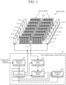
- FIG. 1 is a configuration diagram illustrating an air conditioning system including an air conditioning control device 3 according to a first embodiment.
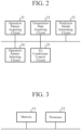
- FIG. 2 is a hardware configuration diagram illustrating hardware of the air conditioning control device 3 according to the first embodiment.
- the air conditioning system illustrated in FIG. 1 is a system that manages a temperature in a room in which electronic devices are installed.
- the electronic devices include computers, communication devices, or the like.
- Examples of the room managed by the air conditioning system include a data center and a server room.
- the air conditioning system illustrated in FIG. 1 includes N air conditioners 1-1 to 1-N, M temperature sensors 2-1 to 2-M, and the air conditioning control device 3.
- N and M is an integer equal to or greater than 2.
- a plurality of server racks is disposed in a data center or the like, and each of the server racks houses a plurality of electronic devices. In the example of FIG. 1 , 14 server racks are disposed.
- the temperature sensors 2-1 to 2-M are installed in the data center or the like.
- the temperature sensors 2-m are installed, for example, at a position 1.5 m above and at a position 2.5 m above the floor of the data center or the like.
- the air conditioning control device 3 includes an operation pattern acquiring unit 11, a temperature data acquiring unit 12, a prediction model generating unit 13, an operation pattern selecting unit 14, and an air conditioner control unit 15.
- the operation pattern acquiring unit 11 is implemented by, for example, an operation pattern acquiring circuit 21 illustrated in FIG. 2 .
- the operation pattern acquiring unit 11 acquires G operation patterns OP 1 to OP G each indicating operation target air conditioners 1-k among the N air conditioners 1-1 to 1-N.
- the number G of the operation patterns OP acquired by the operation pattern acquiring unit 11 is, for example, the number of combinations N C P of selecting P or more air conditioners 1 from N air conditioners 1-1 to 1-N, and P is an integer not less than 1 but less than N.
- the operation pattern acquiring unit 11 outputs the G operation patterns OP 1 to OP G to each of the operation pattern selecting unit 14 and the air conditioner control unit 15.
- the operation pattern acquiring unit 11 may acquire the operation pattern OP g from, for example, a storage device (not illustrated) of the air conditioning control device 3.
- the temperature data acquiring unit 12 is implemented by, for example, a temperature data acquiring circuit 22 illustrated in FIG. 2 .
- the temperature data acquiring unit 12 outputs the acquired temperature data indicating the measurement temperature MT m to the prediction model generating unit 13.
- the prediction model generating unit 13 is implemented by, for example, a prediction model generating circuit 23 illustrated in FIG. 2 .
- the prediction model generating unit 13 acquires the temperature data indicating the measurement temperature MT m from the temperature data acquiring unit 12, and acquires a control amount of the operation target air conditioner 1-k indicated by the operation pattern OP g from the air conditioner control unit 15.
- control amount of the operation target air conditioner 1-k for example, the set temperature of the air conditioner 1-k, the air volume of the air conditioner 1-k, or the frequency of the operating voltage of a compressor connected to the air conditioner 1-k is conceivable.
- the control amount of the air conditioner 1-k is the set temperature of the air conditioner 1-k in the air conditioning system illustrated in FIG. 1 .
- the prediction model generating unit 13 outputs the generated G room-temperature prediction models RTM 1 to RTM G to the operation pattern selecting unit 14.
- the operation pattern selecting unit 14 is implemented by, for example, an operation pattern selecting circuit 24 illustrated in FIG. 2 .
- the operation pattern selecting unit 14 acquires the G operation patterns OP 1 to OP G from the operation pattern acquiring unit 11, and acquires the G room-temperature prediction models RTM 1 to RTM G from the prediction model generating unit 13.
- the operation pattern selecting unit 14 acquires the set temperature PT k of the operation target air conditioner 1-k indicated by the operation pattern OP g from the air conditioner control unit 15.
- the operation pattern selecting unit 14 outputs the selected one operation pattern OP SEL to the air conditioner control unit 15.
- the air conditioner control unit 15 is implemented by, for example, an air conditioner control circuit 25 illustrated in FIG. 2 .
- the air conditioner control unit 15 acquires the G operation patterns OP 1 to OP G from the operation pattern acquiring unit 11.
- the air conditioner control unit 15 operates the operation target air conditioner 1-k indicated by the operation pattern OP g at the set temperature PT k in order to cause the prediction model generating unit 13 to generate the G room-temperature prediction models RTM 1 to RTM G .
- G 3.
- the air conditioner control unit 15 repeatedly performs an operation of the operation target air conditioner 1-k indicated by the operation pattern OP 1 at the set temperature PT k for a certain period of time, and then, after the indoor temperature returns to the temperature before the activation of the operation target air conditioner 1-k, operating again the operation target air conditioner 1-k indicated by the operation pattern OP 1 at the set temperature PT k for a certain period of time.
- the air conditioner control unit 15 repeatedly performs an operation of the operation target air conditioner 1-k indicated by the operation pattern OP 2 at the set temperature PT k for a certain period of time, and then, after the indoor temperature returns to the temperature before the activation of the operation target air conditioner 1-k, performs again an operation of the operation target air conditioner 1-k indicated by the operation pattern OP 2 at the set temperature PT k for a certain period of time.
- the air conditioner control unit 15 repeatedly performs an operation of the operation target air conditioner 1-k indicated by the operation pattern OP 3 at the set temperature PT k for a certain period of time, and then, after the indoor temperature returns to the temperature before the activation of the operation target air conditioner 1-k, performs again an operation of the operation target air conditioner 1-k indicated by the operation pattern OP 3 at the set temperature PT k for a certain period of time.
- the air conditioner control unit 15 When operating the operation target air conditioner 1-k at the set temperature PT k , the air conditioner control unit 15 outputs the set temperature PT k of the air conditioner 1-k to each of the prediction model generating unit 13 and the operation pattern selecting unit 14.
- the set temperature PT k of the operation target air conditioner 1-k may be stored in an internal memory of the air conditioner control unit 15 or may be given from the outside of the air conditioning control device 3.
- the air conditioner control unit 15 operates the operation target air conditioner 1-k indicated by the operation pattern OP SEL selected by the operation pattern selecting unit 14 at the set temperature PT k .
- FIG. 1 illustrates an example in which each of the operation pattern acquiring unit 11, the temperature data acquiring unit 12, the prediction model generating unit 13, the operation pattern selecting unit 14, and the air conditioner control unit 15, which are components of the air conditioning control device 3, is implemented by dedicated hardware as illustrated in FIG. 2 . That is, it is assumed that the air conditioning control device 3 is implemented by the operation pattern acquiring circuit 21, the temperature data acquiring circuit 22, the prediction model generating circuit 23, the operation pattern selecting circuit 24, and the air conditioner control circuit 25.
- each of the operation pattern acquiring circuit 21, the temperature data acquiring circuit 22, the prediction model generating circuit 23, the operation pattern selecting circuit 24, and the air conditioner control circuit 25 is, for example, a single circuit, a composite circuit, a programmed processor, a parallel programmed processor, an application specific integrated circuit (ASIC), a field-programmable gate array (FPGA), or a combination of some of these circuits.
- ASIC application specific integrated circuit
- FPGA field-programmable gate array
- the components of the air conditioning control device 3 are not limited to be implemented by dedicated hardware, and the air conditioning control device 3 may be implemented by software, firmware, or a combination of software and firmware.
- the computer means hardware that executes the program, and may be, for example, a central processing unit (CPU), a central processor, a processing unit, a computing unit, a microprocessor, a microcomputer, a processor, or a digital signal processor (DSP).
- CPU central processing unit
- DSP digital signal processor
- FIG. 3 is a hardware configuration diagram of a computer in a case where the air conditioning control device 3 is implemented by software, firmware, or the like.
- a program for causing the computer to execute the processing procedures performed in the operation pattern acquiring unit 11, the temperature data acquiring unit 12, the prediction model generating unit 13, the operation pattern selecting unit 14, and the air conditioner control unit 15 is stored in a memory 31. Then, a processor 32 of the computer executes the program stored in the memory 31.
- FIG. 2 shows an example in which each of the components of the air conditioning control device 3 is implemented by dedicated hardware
- FIG. 3 shows an example in which the air conditioning control device 3 is implemented by software, firmware, or the like.
- this is merely an example, and some components in the air conditioning control device 3 may be implemented by dedicated hardware, and the remaining components may be implemented by software, firmware, or the like.
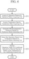
- FIG. 4 is a flowchart illustrating an air conditioning control method which is a processing procedure performed by the air conditioning control device 3.
- the operation pattern acquiring unit 11 acquires G operation patterns OP 1 to OP G indicating the operation target air conditioners 1-k from outside the air conditioning control device 3 (step ST1 in FIG. 4 ).
- the operation pattern acquiring unit 11 outputs the G operation patterns OP 1 to OP G to each of the operation pattern selecting unit 14 and the air conditioner control unit 15.
- the air conditioner control unit 15 acquires the G operation patterns OP 1 to OP G from the operation pattern acquiring unit 11.
- the air conditioner control unit 15 operates the operation target air conditioner 1-k indicated by each operation pattern OP g at the set temperature PT k in order to cause the prediction model generating unit 13 to generate the G room-temperature prediction models RTM 1 to RTM G .
- the operation target air conditioner 1-k indicated by the operation pattern OP 1 is the air conditioners 1-3 and 1-8
- the operation target air conditioner 1-k indicated by the operation pattern OP 2 is the air conditioners 1-5 and 1-10.
- the set temperatures PT k of all the operation target air conditioners 1-k are 19 degrees
- the temperature of the room in which the electronic devices such as a computer are installed is 25 degrees.
- the certain period of time is, for example, 1 hour or 1.5 hours.
- the air conditioner control unit 15 operates the operation target air conditioners 1-3 and 1-8 indicated by the operation pattern OP 1 Q times, for example.
- Q is an integer equal to or greater than 2.
- the air conditioner control unit 15 operates the operation target air conditioners 1-5 and 1-10 indicated by the operation pattern OP 2 Q times, for example.
- the air conditioner control unit 15 When operating the operation target air conditioner 1-k at the set temperature PT k , the air conditioner control unit 15 outputs the set temperature PT k of the air conditioner 1-k to each of the prediction model generating unit 13 and the operation pattern selecting unit 14. In addition, the air conditioner control unit 15 outputs a request to generate the room-temperature prediction model RTM g corresponding to each operation pattern OP g to the prediction model generating unit 13.
- the air conditioner control unit 15 outputs, to the temperature data acquiring unit 12, a data acquisition request to instruct acquisition of temperature data for a certain period of time after the operation target air conditioner 1-k starts operation.
- the temperature data acquiring unit 12 acquires temperature data indicating the measurement temperature MT m which is the temperature measured by the temperature sensor 2-m during operation of each of the air conditioners 1-3 and 1-8. Therefore, the temperature data acquiring unit 12 acquires Q pieces of temperature data when the operation target air conditioners 1-3 and 1-8 indicated by the operation pattern OP 1 are operated.
- the temperature data acquiring unit 12 acquires temperature data indicating the measurement temperature MT m which is the temperature measured by the temperature sensor 2-m during operation of each of the air conditioners 1-5 and 1-10. Therefore, the temperature data acquiring unit 12 acquires Q pieces of temperature data when the operation target air conditioners 1-5 and 1-10 indicated by the operation pattern OP 2 are operated.
- the temperature data acquiring unit 12 outputs the acquired G x Q pieces of temperature data indicating the measurement temperature MT m to the prediction model generating unit 13.
- the prediction model generating unit 13 acquires G x Q pieces of temperature data from the temperature data acquiring unit 12.
- First data set set temperature PT k of air conditioner 1 ⁇ k + first temperature data
- Second data set set temperature PT k of air conditioner 1 ⁇ k + second temperature data :
- Qth data set set temperature PT k of air conditioner 1 ⁇ k + Qth temperature data
- the prediction model generating unit 13 provides the first data set to the untrained room-temperature prediction model RTM g , and performs training to change the internal parameter of the room-temperature prediction model RTM g in such a way that a prediction temperature FT g output from the room-temperature prediction model RTM g approaches the measurement temperature MT m indicated by the first temperature data.
- the prediction model generating unit 13 provides the second data set to the room-temperature prediction model RTM g which has been trained by the first data set, and performs training to change the internal parameter of the room-temperature prediction model RTM g in such a way that the prediction temperature FT g output from the room-temperature prediction model RTM g approaches the measurement temperature MT m indicated by the second temperature data.
- the room-temperature prediction model RTM g may be any machine learning model that can output the prediction temperature FT g of the temperature measured by the temperature sensor 2-m after a certain period of time when receiving the set temperature PT k of the operation target air conditioner 1-k, and may be of any type of prediction model.
- Examples of the room-temperature prediction model RTM g include a linear regression model, a gradient boosting tree, and a neural network.
- a process for generating the room-temperature prediction model RTM g is a known technique, and thus, the detailed description thereof will be omitted.
- the prediction model generating unit 13 outputs the generated G room-temperature prediction models RTM 1 to RTM G to the operation pattern selecting unit 14.
- the prediction model generating unit 13 generates the room-temperature prediction model RTM g using Q data sets as training data.
- the prediction model generating unit 13 may prepare Q data sets each including the power consumption and the like of all the electronic devices installed in the data center and the like, and may generate the room-temperature prediction model RTM g using Q data sets including the power consumption and the like of the electronic devices as the training data.
- the operation pattern selecting unit 14 acquires the G operation patterns OP 1 to OP G from the operation pattern acquiring unit 11, and acquires the G room-temperature prediction models RTM 1 to RTM G from the prediction model generating unit 13.
- the operation pattern selecting unit 14 acquires the set temperature PT k of the operation target air conditioner 1-k indicated by the operation pattern OP g from the air conditioner control unit 15.
- the operation pattern selecting unit 14 outputs the selected one operation pattern OP SEL to the air conditioner control unit 15.
- the temperature upper limit value T max is the highest possible indoor temperature that does not affect the electronic device, and is several degrees higher than the set temperature PT k .
- the temperature upper limit value T max may be stored in the internal memory of the operation pattern selecting unit 14 or may be given from the outside of the air conditioning control device 3.
- the prediction accuracy of the room-temperature prediction model RTM g is output from the room-temperature prediction model RTM g .
- the threshold may be 1.5 degrees, 2 degrees, or the like. Therefore, when the threshold is, for example, 1.5 degrees, the room-temperature prediction model RTM g whose prediction accuracy is within 1.5 degrees is selected.
- the threshold may be stored in the internal memory of the operation pattern selecting unit 14 or may be given from the outside of the air conditioning control device 3.
- the operation pattern selecting unit 14 selects one operation pattern in which the number of operation target air conditioners 1-k is relatively small from among one or more operation patterns tentatively selected. That is, the operation pattern selecting unit 14 selects the operation pattern in which the number of operation target air conditioners 1-k is the smallest as the operation pattern OP SEL from among the one or more operation patterns tentatively selected.
- the air conditioner control unit 15 acquires the operation pattern OP SEL from the operation pattern selecting unit 14.
- the air conditioner control unit 15 operates the operation target air conditioner 1-k indicated by the operation pattern OP SEL at the set temperature PT k (step ST5 in FIG. 4 ).
- the air conditioning control device 3 includes: the operation pattern acquiring unit 11 to acquire a plurality of operation patterns indicating an operation target air conditioner 1-k among a plurality of air conditioners 1-1 to 1-N installed in a room; and the temperature data acquiring unit 12 to acquire temperature data indicating measurement temperatures of the temperature sensors 2-1 to 2-M installed in the room when the operation target air conditioner 1-k indicated by each of the operation patterns is in operation.
- the air conditioning control device 3 also includes the prediction model generating unit 13 to generate, using a control amount of the operation target air conditioner 1-k indicated by each of the operation patterns and temperature data acquired by the temperature data acquiring unit 12 when the operation target air conditioner 1-k is in operation as training data, a room-temperature prediction model for predicting the temperatures measured by the temperature sensors 2-1 to 2-M when the operation target air conditioner 1-k indicated by each of the operation patterns is in operation.
- the air conditioning control device 3 further includes the operation pattern selecting unit 14 to provide the control amount of the operation target air conditioner 1-k indicated by each of the operation patterns to room-temperature prediction models corresponding to the respective operation patterns, generated by the prediction model generating unit 13, acquire a prediction temperature from each of the room-temperature prediction models, and selects one operation pattern from the plurality of operation patterns on the basis of the prediction temperature. Accordingly, the air conditioning control device 3 can determine the air conditioner 1-k to be actually operated among the plurality of air conditioners 1-1 to 1-N without acquiring layout data.
- the prediction model generating unit 13 generates the G room-temperature prediction models RTM 1 to RTM G , and then, the operation pattern selecting unit 14 selects one operation pattern OP SEL from the operation patterns OP g corresponding to the respective G room-temperature prediction models RTM 1 to RTM G .
- the operation pattern selecting unit 14 may select one operation pattern OP SEL as follows.
- FIG. 5 is a flowchart illustrating a part of the processing procedure performed by the air conditioning control device 3.
- J ⁇ G is established.
- the air conditioner control unit 15 acquires J operation patterns OP j .
- J is an integer equal to or greater than 1 and equal to or less than G.
- the operation pattern OP g and the operation pattern OP j are basically different from each other.
- the air conditioner control unit 15 operates the operation target air conditioner 1-k indicated by the operation pattern OP j out of the J operation patterns OP 1 to OP J at the set temperature PT k for a certain period of time (step ST12 in FIG. 5 ).
- the air conditioner control unit 15 operates the operation target air conditioner 1-k indicated by the operation pattern OP j Q times, for example.
- the air conditioner control unit 15 When operating the operation target air conditioner 1-k at the set temperature PT k , the air conditioner control unit 15 outputs the set temperature PT k of the air conditioner 1-k to each of the prediction model generating unit 13 and the operation pattern selecting unit 14. In addition, the air conditioner control unit 15 outputs a request to generate a room-temperature prediction model RTM j corresponding to the operation pattern OP j to the prediction model generating unit 13.
- the air conditioner control unit 15 When operating the operation target air conditioner 1-k, the air conditioner control unit 15 outputs a data acquisition request to the temperature data acquiring unit 12.
- the temperature data acquiring unit 12 outputs the acquired Q pieces of temperature data to the prediction model generating unit 13.
- the prediction model generating unit 13 acquires, from the temperature data acquiring unit 12, Q pieces of temperature data when the operation target air conditioner 1-k indicated by the operation pattern OP j is operated at the set temperature PT k .
- the prediction model generating unit 13 acquires, from the air conditioner control unit 15, the set temperature PT k of the operation target air conditioner 1-k indicated by the operation pattern OP j and a request to generate the room-temperature prediction model RTM j corresponding to the operation pattern OP j .
- the prediction model generating unit 13 When acquiring the request to generate the room-temperature prediction model RTM j , the prediction model generating unit 13 prepares the above-described Q data sets from the Q pieces of temperature data and the set temperature PT k .
- the prediction model generating unit 13 sequentially provides the data sets to the room-temperature prediction model RTM j , and repeatedly performs training to change the internal parameter of the room-temperature prediction model RTM j in such a way that a prediction temperature FT j output from the room-temperature prediction model RTM j approaches the measurement temperature MT m indicated by the temperature data.
- the prediction model generating unit 13 provides Q data sets to the room-temperature prediction model RTM j .
- the prediction model generating unit 13 continues the machine learning of the room-temperature prediction model RTM j by repeatedly providing the data sets to the room-temperature prediction model RTM j , to thereby generate the room-temperature prediction model RTM j having the prediction accuracy equal to or higher than the threshold (step ST14 in FIG. 5 ).
- the prediction model generating unit 13 outputs the room-temperature prediction model RTM j having the prediction accuracy equal to or higher than the threshold to the operation pattern selecting unit 14.
- the air conditioner control unit 15 operates the operation target air conditioner 1-k indicated by the operation pattern OP j in which the operation target air conditioner 1-k has not yet been operated at the set temperature PT k for a certain period of time (step ST12 in FIG. 5 ).
- the air conditioner control unit 15 operates the operation target air conditioner 1-k indicated by the operation pattern OP j Q times, for example.
- the air conditioner control unit 15 When operating the operation target air conditioner 1-k at the set temperature PT k , the air conditioner control unit 15 outputs the set temperature PT k of the air conditioner 1-k to each of the prediction model generating unit 13 and the operation pattern selecting unit 14. In addition, the air conditioner control unit 15 outputs a request to generate a room-temperature prediction model RTM j corresponding to the operation pattern OP j to the prediction model generating unit 13.
- the air conditioner control unit 15 When operating the operation target air conditioner 1-k, the air conditioner control unit 15 outputs a data acquisition request to the temperature data acquiring unit 12.
- the temperature data acquiring unit 12 outputs the acquired Q pieces of temperature data to the prediction model generating unit 13.
- the prediction model generating unit 13 acquires, from the temperature data acquiring unit 12, Q pieces of temperature data when the operation target air conditioner 1-k indicated by the operation pattern OP j is operated at the set temperature PT k .
- the prediction model generating unit 13 acquires, from the air conditioner control unit 15, the set temperature PT k of the operation target air conditioner 1-k indicated by the operation pattern OP j and a request to generate the room-temperature prediction model RTM j corresponding to the operation pattern OP j .
- the prediction model generating unit 13 When acquiring the request to generate the room-temperature prediction model RTM j , the prediction model generating unit 13 prepares the above-described Q data sets from the Q pieces of temperature data and the set temperature PT k .
- the prediction model generating unit 13 sequentially provides the data sets to the room-temperature prediction model RTM j , and repeatedly performs training to change the internal parameter of the room-temperature prediction model RTM j in such a way that a prediction temperature FT j output from the room-temperature prediction model RTM j approaches the measurement temperature MT m indicated by the temperature data.
- the prediction model generating unit 13 may not provide all the data sets to the room-temperature prediction model RTM j when the prediction accuracy of the room-temperature prediction model RTM j reaches or is beyond the threshold before providing the Q data sets to the room-temperature prediction model RTM j .
- the prediction model generating unit 13 continues the machine learning of the room-temperature prediction model RTM j by repeatedly providing the data sets to the room-temperature prediction model RTM j , to thereby generate the room-temperature prediction model RTM j having the prediction accuracy equal to or higher than the threshold (step ST14 in FIG. 5 ).
- the prediction model generating unit 13 outputs the room-temperature prediction model RTM j having the prediction accuracy equal to or higher than the threshold to the operation pattern selecting unit 14.
- the operation pattern selecting unit 14 selects one room-temperature prediction model as the room-temperature prediction model RTM j,N-3 from among the J room-temperature prediction models RTM 1 to RTM J having prediction accuracy equal to or higher than the threshold.
- the operation pattern selecting unit 14 selects one or more room-temperature prediction models RTM j in which the prediction temperature FT j is equal to or lower than the temperature upper limit value T max from among the J room-temperature prediction models RTM 1 to RTM J having prediction accuracy equal to or higher than the threshold.
- the operation pattern selecting unit 14 selects the room-temperature prediction model RTM j having the highest prediction temperature FT j as the room-temperature prediction model RTM j,N-3 from among the one or more room-temperature prediction models RTM j having a prediction temperature FT j equal to or lower than the temperature upper limit value T max .
- the operation pattern selecting unit 14 determines the operation pattern OP j corresponding to the selected room-temperature prediction model RTM j as a candidate OP SEL,N-3 for the operation pattern (step ST16 in FIG. 5 ).
- the air conditioner control unit 15 acquires the operation pattern OP j in which the number of the operation target air conditioners 1-k is one less (step ST18 in FIG. 5 ).
- the air conditioner control unit 15 acquires J' operation patterns OP 1 to OP J' .
- J' ⁇ G - J is established.
- steps ST12 to ST15 are also repeated for the operation pattern OP j in which the number of the operation target air conditioners 1-k is (N -4).
- the operation pattern selecting unit 14 selects the room-temperature prediction model RTM j having the highest prediction temperature FT j as the room-temperature prediction model RTM j,N-4 from among the one or more room-temperature prediction models RTM j .
- the operation pattern selecting unit 14 determines the operation pattern OP j corresponding to the selected room-temperature prediction model RTM j as a candidate OP SEL,N-4 for the operation pattern (step ST16 in FIG. 5 ).
- the operation patterns OP 1 to OP G excluding the J operation patterns OP 1 to OP J and J' operation patterns OP 1 to OP J include the operation pattern OP j in which the number of the operation target air conditioners 1-k is one less than the number of the operation target air conditioners 1-k indicated by the J' operation patterns OP j which have been already acquired, a candidate for the operation pattern is further determined by a manner similar to the manner described above. Then, a candidate OP SEL,N-5 for one operation pattern is selected.
- the operation pattern selecting unit 14 selects one operation pattern OP SEL from among one or more operation pattern candidates (step ST19 in FIG. 5 ).
- the operation pattern selecting unit 14 selects a candidate for the operation pattern in which the number of the operation target air conditioners 1-k is the smallest from among the one or more operation pattern candidates as one operation pattern OP SEL .
- the operation pattern selecting unit 14 selects the candidate OP SEL,N-5 for the operation pattern as the operation pattern OP SEL .
- the second embodiment describes an air conditioning control device 3 including a control amount changing unit 16 that changes a control amount of an operation target air conditioner 1-k indicated by an operation pattern selected by an operation pattern selecting unit 14.
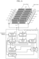
- FIG. 6 is a configuration diagram illustrating an air conditioning system including the air conditioning control device 3 according to the second embodiment.
- elements same as or corresponding to the elements in FIG. 1 are identified by the same reference numerals, and thus, the description thereof will be omitted.
- FIG. 7 is a hardware configuration diagram illustrating hardware of the air conditioning control device 3 according to the second embodiment.
- elements same as or corresponding to the elements in FIG. 2 are identified by the same reference numerals, and thus, the description thereof will be omitted.
- the air conditioning control device 3 illustrated in FIG. 6 includes an operation pattern acquiring unit 11, a temperature data acquiring unit 12, a prediction model generating unit 13, the operation pattern selecting unit 14, the control amount changing unit 16, a training execution unit 17, a set temperature determining unit 18, and an air conditioner control unit 19.
- the control amount changing unit 16 is implemented by, for example, a control amount changing circuit 26 illustrated in FIG. 7 .
- the control amount changing unit 16 changes a control amount of the operation target air conditioner 1-k indicated by an operation pattern OP SEL selected by the operation pattern selecting unit 14.
- the control amount changing unit 16 changes the set temperature PT k of the air conditioner 1-k as the control amount of the air conditioner 1-k.
- the control amount changing unit 16 may change, as the control amount of the air conditioner 1-k, the air volume of the air conditioner 1-k or the frequency of an operating voltage of a compressor connected to the air conditioner 1-k.
- the training execution unit 17 is implemented by, for example, a training execution circuit 27 illustrated in FIG. 7 .
- the training execution unit 17 acquires the temperature data acquired by the temperature data acquiring unit 12 when the operation target air conditioner 1-k indicated by the operation pattern OP SEL selected by the operation pattern selecting unit 14 is operating, and the set temperature PT k that is the control amount changed by the control amount changing unit 16.
- the training execution unit 17 provides the acquired temperature data and the changed set temperature PT k to the room-temperature prediction model RTM g corresponding to the operation pattern OP SEL selected by the operation pattern selecting unit 14, and trains the room-temperature prediction model RTM g to learn the temperature measured by the temperature sensor 2-m when the operation target air conditioner 1-k indicated by the operation pattern OP SEL is operating.
- the set temperature determining unit 18 is implemented by, for example, a set temperature determining circuit 28 illustrated in FIG. 7 .
- the set temperature determining unit 18 provides, as a tentatively set temperature PT k of the air conditioner 1-k, any one of a plurality of temperatures included in a settable temperature range of the air conditioner 1-k to the room-temperature prediction model RTM g that has been trained by the training execution unit 17, and acquires an indoor prediction temperature FT g from the trained room-temperature prediction model RTM g .
- the set temperature determining unit 18 determines the set temperature PT k of the air conditioner 1-k on the basis of the prediction temperature FT g and the temperature upper limit value T max .
- the air conditioner control unit 19 is implemented by, for example, an air conditioner control circuit 29 illustrated in FIG. 7 .
- the air conditioner control unit 19 operates the operation target air conditioner 1-k indicated by the operation pattern OP SEL selected by the operation pattern selecting unit 14 at the set temperature PT k determined by the set temperature determining unit 18.
- FIG. 6 illustrates an example in which each of the operation pattern acquiring unit 11, the temperature data acquiring unit 12, the prediction model generating unit 13, the operation pattern selecting unit 14, the control amount changing unit 16, the training execution unit 17, the set temperature determining unit 18, and the air conditioner control unit 19, which are components of the air conditioning control device 3, is implemented by dedicated hardware as illustrated in FIG. 7 . That is, it is assumed that the air conditioning control device 3 is implemented by the operation pattern acquiring circuit 21, the temperature data acquiring circuit 22, the prediction model generating circuit 23, the operation pattern selecting circuit 24, the control amount changing circuit 26, the training execution circuit 27, the set temperature determining circuit 28, and the air conditioner control circuit 29.
- each of the operation pattern acquiring circuit 21, the temperature data acquiring circuit 22, the prediction model generating circuit 23, the operation pattern selecting circuit 24, the control amount changing circuit 26, the training execution circuit 27, the set temperature determining circuit 28, and the air conditioner control circuit 29 is, for example, a single circuit, a composite circuit, a programmed processor, a parallel programmed processor, an ASIC, a FPGA, or a combination of some of these circuits.
- the components of the air conditioning control device 3 are not limited to be implemented by dedicated hardware, and the air conditioning control device 3 may be implemented by software, firmware, or a combination of software and firmware.
- the air conditioning control device 3 is implemented by software, firmware, or the like
- a program for causing a computer to execute the processing procedures performed in the operation pattern acquiring unit 11, the temperature data acquiring unit 12, the prediction model generating unit 13, the operation pattern selecting unit 14, the control amount changing unit 16, the training execution unit 17, the set temperature determining unit 18, and the air conditioner control unit 19 is stored in the memory 31 illustrated in FIG. 3 .
- the processor 32 illustrated in FIG. 3 executes the program stored in the memory 31.
- FIG. 7 shows an example in which each of the components of the air conditioning control device 3 is implemented by dedicated hardware
- FIG. 3 shows an example in which the air conditioning control device 3 is implemented by software, firmware, or the like.
- this is merely an example, and some components in the air conditioning control device 3 may be implemented by dedicated hardware, and the remaining components may be implemented by software, firmware, or the like.
- the air conditioning system is similar to the air conditioning system illustrated in FIG. 1 except for the control amount changing unit 16, the training execution unit 17, the set temperature determining unit 18, and the air conditioner control unit 19.
- the control amount changing unit 16 the training execution unit 17, the set temperature determining unit 18, and the air conditioner control unit 19.
- operations of the control amount changing unit 16, the training execution unit 17, the set temperature determining unit 18, and the air conditioner control unit 19 will be described.
- the control amount changing unit 16 acquires one selected operation pattern OP SEL from the operation pattern selecting unit 14, and acquires the set temperature PT k of the air conditioner 1-k as the control amount of the operation target air conditioner 1-k indicated by the operation pattern OP SEL from the air conditioner control unit 19.
- the control amount changing unit 16 changes the set temperature PT k of the operation target air conditioner 1-k indicated by the operation pattern OP SEL .
- the control amount changing unit 16 changes the set temperature PT k of the air conditioner 1-k by a method called active learning in order to train the room-temperature prediction model RTM g corresponding to the operation pattern OP SEL to efficiently learn the measurement temperature MT m .
- a temperature farthest from the current set temperature in the settable temperature range of the air conditioner 1-k is determined as the next set temperature, and a temperature farthest from the set temperature that has been determined is further determined as the next set temperature.
- the control amount changing unit 16 calculates a temperature difference ⁇ PT k between each of temperatures other than the set temperature PT k that is currently set and the set temperature PT k that is currently set among the plurality of temperatures included in the settable temperature range of the air conditioner 1-k.
- a plurality of temperatures included in the settable temperature range is 19 degrees, 20 degrees, 21 degrees, 22 degrees, and 23 degrees, and the currently set temperature PT k is 19 degrees.
- the control amount changing unit 16 selects the changed set temperature PT k from the plurality of temperatures included in the temperature range on the basis of the calculated temperature differences ⁇ PT k .
- the set temperature PT k of the air conditioner 1-k is changed as follows. 19 degrees ⁇ 23 degrees ⁇ 20 degrees ⁇ 22 degrees ⁇ 21 degrees
- the control amount changing unit 16 outputs set temperature changing information indicating the detail of the change of the set temperature PT k of the air conditioner 1-k to the air conditioner control unit 19.
- the set temperature changing information indicates that the set temperature PT k is changed in the order of 23 degrees, 20 degrees, 22 degrees, and 21 degrees from 19 degrees.
- the air conditioner control unit 19 acquires the set temperature changing information from the control amount changing unit 16, and acquires the operation pattern OP SEL from the operation pattern selecting unit 14.
- the air conditioner control unit 19 operates the operation target air conditioner 1-k indicated by the operation pattern OP SEL by switching the set temperature PT k of the air conditioner 1-k in the order indicated by the set temperature changing information.
- the high accuracy A ns means that the prediction accuracy of the room-temperature prediction model RTM g is practically satisfactory, and may be, for example, 0.5 degrees or 0.6 degrees.
- the training execution unit 17 acquires one selected operation pattern OP SEL from the operation pattern selecting unit 14.
- the prediction accuracy of the room-temperature prediction model RTM g is improved by learning.
- the accuracy of the prediction temperature FT g output from the prediction model RTM g is improved.
- the training execution unit 17 outputs the prediction accuracy of the room-temperature prediction model RTM g which has been trained to the air conditioner control unit 19.
- the air conditioner control unit 19 When operating the operation target air conditioner 1-k, the air conditioner control unit 19 outputs a data acquisition request to the temperature data acquiring unit 12.
- the air conditioner control unit 19 does not thereafter operate the air conditioner 1-k for enhancing the prediction accuracy of the room-temperature prediction model RTM g .
- the training execution unit 17 outputs the prediction accuracy of the room-temperature prediction model RTM g which has been trained to the air conditioner control unit 19.
- the air conditioner control unit 19 When operating the operation target air conditioner 1-k, the air conditioner control unit 19 outputs a data acquisition request to the temperature data acquiring unit 12.
- the air conditioner control unit 19 does not thereafter operate the air conditioner 1-k for enhancing the prediction accuracy of the room-temperature prediction model RTM g .
- the training execution unit 17 outputs the prediction accuracy of the room-temperature prediction model RTM g which has been trained to the air conditioner control unit 19.
- the air conditioner control unit 19 When operating the operation target air conditioner 1-k, the air conditioner control unit 19 outputs a data acquisition request to the temperature data acquiring unit 12.
- the air conditioner control unit 19 does not thereafter operate the air conditioner 1-k for enhancing the prediction accuracy of the room-temperature prediction model RTM g .
- the room-temperature prediction model RTM g is efficiently trained by the training execution unit 17 by changing the set temperature PT k of the air conditioner 1-k by a method called active learning. Therefore, it is presumed that the prediction accuracy of the room-temperature prediction model RTM g is equal to or higher than the high accuracy A ns before all of the plurality of temperatures included in the settable temperature range of the air conditioner 1-k are set as the set temperature PT k . Accordingly, the accuracy of the room-temperature prediction model RTM g is improved more quickly by changing the set temperature PT k with a method called active learning than by, for example, setting the temperatures included in the settable temperature range as the set temperature PT k in the order from a lower to a higher temperature.
- the time required for training the room-temperature prediction model RTM g is shortened as compared with the case where the temperatures are set as the set temperature PT k in the order from a lower to a higher temperature.
- the set temperature determining unit 18 determines each of the plurality of temperatures included in the settable temperature range of the air conditioner 1-k as a tentatively set temperature PT k ' of the air conditioner 1-k.
- the set temperature determining unit 18 provides each of the tentatively set temperatures PT k ' to the room-temperature prediction model RTM g that has been trained by the training execution unit 17, and acquires the prediction temperature FT g from each of the trained room-temperature prediction models RTM g .
- the set temperature determining unit 18 specifies a prediction temperature FT g equal to or lower than the temperature upper limit value T max among the plurality of prediction temperatures FT g .
- the set temperature determining unit 18 determines the highest temperature among the prediction temperatures FT g equal to or lower than the temperature upper limit value T max as the set temperature PT k of the air conditioner 1-k as illustrated in FIG. 8 .
- FIG. 8 is an explanatory diagram illustrating candidates for the set temperature PT k determined by the set temperature determining unit 18.
- the horizontal axis indicates a time, and "Now" indicates a current time.
- the vertical axis represents the indoor temperature.
- the prediction temperature FT g is equal to or lower than the temperature upper limit value T max when the tentatively set temperature PT k ' is 19 degrees, 20 degrees, and 21 degrees.
- the prediction temperature FT g when the tentatively set temperature PT k ' is 21 degrees is the highest temperature among the prediction temperatures FT g when the tentatively set temperature PT k ' is 19 degrees, 20 degrees, and 21 degrees, and thus, the set temperature determining unit 18 determines 21 degrees as the set temperature PT k of the air conditioner 1-k.
- the set temperature determining unit 18 outputs the determined set temperature PT k of the air conditioner 1-k to the air conditioner control unit 19.
- the air conditioner control unit 19 operates the operation target air conditioner 1-k indicated by the operation pattern OP SEL at the set temperature PT k determined by the set temperature determining unit 18.
- the air conditioning control device 3 includes: the control amount changing unit 16 to change the control amount of the operation target air conditioner 1-k indicated by the operation pattern selected by the operation pattern selecting unit 14; and the training execution unit 17 to provide, as training data, the control amount that has been changed by the control amount changing unit 16 and the temperature data acquired by the temperature data acquiring unit 12 when the operation target air conditioner 1-k indicated by the operation pattern selected by the operation pattern selecting unit 14 is in operation to the room-temperature prediction model corresponding to the operation pattern selected by the operation pattern selecting unit 14, and train the room-temperature prediction model to learn the temperature measured by the temperature sensor 2-m when the operation target air conditioner is in operation. Accordingly, the air conditioning control device 3 can determine the air conditioner 1-k to be actually operated among the plurality of air conditioners 1-1 to 1-N without acquiring layout data, and further, can change the control amount of the operation target air conditioner 1-k.
- the control amount of the operation target air conditioner 1-k is a set temperature of the air conditioner 1-k
- the air conditioning control device 3 includes the set temperature determining unit 18 to provide, to the room-temperature prediction model that has been trained by the training execution unit 17, any of a plurality of temperatures included in a settable temperature range of the air conditioner 1-k as a tentatively set temperature of the air conditioner 1-k to acquire a prediction temperature from the room-temperature prediction model that has been trained, and determine the set temperature of the air conditioner 1-k on the basis of the prediction temperature and the temperature upper limit value.
- the air conditioning control device 3 can determine the set temperature at which the power consumption can be reduced within a range in which the indoor temperature does not exceed the temperature upper limit value.
- control amount changing unit 16 changes the set temperature PT k of the air conditioner 1-k by a method called active learning.
- the process of changing the set temperature PT k by a method called active learning is not limited to determine a temperature farthest from the current set temperature in the settable temperature range of the air conditioner 1-k as the next set temperature, and the control amount changing unit 16 may determine the next set temperature as follows.
- the control amount changing unit 16 obtains an evaluation value indicating the accuracy of the room-temperature prediction model RTM g with respect to each set temperature PT k when each of the plurality of temperatures included in the settable temperature range of the air conditioner 1-k is set to the set temperature PT k using Bayesian optimization, for example.
- the evaluation value is larger as the accuracy of the room-temperature prediction model RTM g with respect to the set temperature PT k is higher. Since the Bayesian optimization is a known technique, the detailed description thereof will be omitted.
- evaluation values indicating the accuracy of the room-temperature prediction models RTM g with respect to two set temperatures PT k are known in a case where the Bayesian optimization is used, evaluation values indicating the accuracy of the room-temperature prediction models RTM g with respect to the remaining set temperatures PT k are obtained.
- FIG. 9 is an explanatory diagram illustrating accuracy of the room-temperature prediction model RTM g with respect to the set temperature PT k .
- • indicates the set temperature PT k that has been set.
- a solid line indicates a prediction temperature FT g which is an output temperature of the room-temperature prediction model RTM g with respect to the set temperature PT k , and a dotted line indicates a true value of the prediction temperature FT g .
- the interval between the solid line and the dotted line represents an evaluation value indicating the accuracy of the room-temperature prediction model RTM g with respect to the set temperature PT k .
- the lengths of arrows (1) to (4) indicate the interval between the solid line and the dotted line. The narrower the interval between the solid line and the dotted line, the higher the evaluation value. In the example of FIG. 9 , length of arrow (1) ⁇ length of arrow (2) ⁇ length of arrow (4) ⁇ length of arrow (3). In the drawing, the gray area indicates an area in which the reliability of the room-temperature prediction model RTM g is about 95%.
- the control amount changing unit 16 compares evaluation values indicating the accuracy of the room-temperature prediction models RTM g with respect to temperatures that have not yet been set as the set temperature PT k among the plurality of temperatures included in the settable temperature range of the air conditioner 1-k.
- the temperatures that have not yet been set as the set temperature PT k are, for example, the temperatures corresponding to the arrows (1) to (4), the lengths of the arrows (1) to (4) are compared with each other.
- the control amount changing unit 16 determines the temperature having the smallest evaluation value as the next set temperature PT k , and further determines the temperature having the second smallest evaluation value as the set temperature PT k next to the immediately preceding set temperature PT k on the basis of the comparison result of the evaluation values. Thereafter, the control amount changing unit 16 determines the set temperatures PT k in ascending order of evaluation values.
- the control amount changing unit 16 first determines the temperature corresponding to the arrow (3) having the smallest evaluation value as the next set temperature PT k , and determines the temperature corresponding to the arrow (4) having the second smallest evaluation value as the set temperature PT k next to the immediately preceding set temperature PT k .
- the control amount changing unit 16 determines the temperature corresponding to the arrow (2) having the third smallest evaluation value as the set temperature PT k next to the immediately preceding set temperature PT k , and in the end, determines the temperature corresponding to the arrow (1) having the largest evaluation value as the set temperature PT k next to the immediately preceding set temperature PT k .
- the room-temperature prediction model RTM g is effectively trained to learn the measurement temperature MT m .
- control amount changing unit 16 determines the set temperature PT k in order of the length of arrow. However, this is merely an example, and the control amount changing unit 16 may preferentially determine the temperature included in a large gray area as the set temperature PT k .
- the control amount changing unit 16 determines, for example, the temperature corresponding to the arrow (2) as the set temperature PT k before the temperature corresponding to the arrow (1). However, the control amount changing unit 16 may determine the temperature corresponding to the arrow (1) as the set temperature PT k before the temperature corresponding to the arrow (2) on the basis of the size of the gray area.
- the training execution unit 17 trains the operation pattern OP SEL selected by the operation pattern selecting unit 14 to learn the temperature measured by the temperature sensor 2-m, and then, the air conditioner control unit 19 operates the operation target air conditioner 1-k indicated by the trained operation pattern OP SEL at the set temperature PT k determined by the set temperature determining unit 18.
- the operation pattern OP SEL selected by the operation pattern selecting unit 14 may be changed depending on a change in an operation mode or the like of an electronic device installed in a data center or the like. In such a case, the training execution unit 17 may train the changed operation pattern OP SEL to learn the temperature measured by the temperature sensor 2-m.
- any embodiments can be freely combined to each other, or any component in the embodiments can be modified or omitted.
- the air conditioning control device can be used for air-conditioning control of a server room or the like, for example.
- 1-1 to 1-12 air conditioner, 2-1 to 2-2: temperature sensor, 3: air conditioning control device, 11: operation pattern acquiring unit, 12: temperature data acquiring unit, 13: prediction model generating unit, 14: operation pattern selecting unit, 15: air conditioner control unit, 16: control amount changing unit, 17: training execution unit, 18: set temperature determining unit, 19: air conditioner control unit, 21: operation pattern acquiring circuit, 22: temperature data acquiring circuit, 23: prediction model generating circuit, 24: operation pattern selecting circuit, 25: air conditioner control circuit, 26: control amount changing circuit, 27: training execution circuit, 28: set temperature determining circuit, 29: air conditioner control circuit, 31: memory, 32: processor
Landscapes
- Engineering & Computer Science (AREA)
- Signal Processing (AREA)
- General Engineering & Computer Science (AREA)
- Physics & Mathematics (AREA)
- Chemical & Material Sciences (AREA)
- Combustion & Propulsion (AREA)
- Mechanical Engineering (AREA)
- Fuzzy Systems (AREA)
- Mathematical Physics (AREA)
- Thermal Sciences (AREA)
- Microelectronics & Electronic Packaging (AREA)
- Computer Hardware Design (AREA)
- Air Conditioning Control Device (AREA)
Abstract
Description
- The present disclosure relates to an air conditioning control device and an air conditioning control method.
- A plurality of electronic devices is installed in a data center, a server room, or the like. The electronic devices include computers, communication devices, or the like. A plurality of air conditioners is installed in the data center or the like in order to suppress an increase in indoor temperature due to heat generated from the electronic devices. When some air conditioners among the plurality of air conditioners installed in the data center or the like are operated, the temperature of the data center or the like may be maintained at a certain temperature or lower. In order to suppress the power consumption of the air conditioners, it is desirable that the number of air conditioners to be actually operated is small. An air conditioner that is not actually operated is used as a backup machine.
- Some air conditioning control devices that control a plurality of air conditioners installed in a server room can determine one or more air conditioners to be actually operated among the plurality of air conditioners (hereinafter referred to as "conventional air conditioning control device", see Patent Literature 1). The conventional air conditioning control device acquires layout data indicating a position of a hot aisle that is a path through which high-temperature air discharged from electronic devices passes and positions of a plurality of air conditioners. Then, the conventional air conditioning control device determines one or more air conditioners to be actually operated among the plurality of air conditioners on the basis of the layout data.
- Patent Literature 1:
JP 2018-005646 A - The conventional air conditioning control device has a problem that, if the layout data cannot be acquired, it is impossible to determine one or more air conditioners to be actually operated among the plurality of air conditioners installed in the server room.
- The present disclosure has been made to solve the above problem, and an object thereof is to obtain an air conditioning control device and an air conditioning control method with which it is possible to determine one or more air conditioners to be actually operated among a plurality of air conditioners without acquiring layout data.
- An air conditioning control device according to the present disclosure includes: an operation pattern acquiring unit to acquire a plurality of operation patterns each indicating at least one operation target air conditioner among a plurality of air conditioners installed in a room; a temperature data acquiring unit to acquire temperature data indicating a measurement temperature of a temperature sensor installed in the room when the at least one operation target air conditioner indicated by each of the plurality of operation patterns is in operation; a prediction model generating unit to generate, using a control amount of the at least one operation target air conditioner indicated by each of the plurality of operation patterns and the temperature data acquired by the temperature data acquiring unit when the at least one operation target air conditioner is in operation as training data, a room-temperature prediction model, which corresponds to each of the plurality of operation patterns, for predicting a temperature measured by the temperature sensor when the at least one operation target air conditioner indicated by each of the plurality of operation patterns is in operation; and an operation pattern selecting unit to acquire a prediction temperature from the room-temperature prediction model by providing the control amount of the at least one operation target air conditioner indicated by each of the plurality of operation patterns to the room-temperature prediction model generated by the prediction model generating unit, and selects one operation pattern from the plurality of operation patterns on a basis of the prediction temperature.
- According to the present disclosure, it is possible to determine one or more air conditioners to be actually operated among a plurality of air conditioners without acquiring layout data.
-
-
FIG. 1 is a configuration diagram illustrating an air conditioning system including an airconditioning control device 3 according to a first embodiment. -
FIG. 2 is a hardware configuration diagram illustrating hardware of the airconditioning control device 3 according to the first embodiment. -
FIG. 3 is a hardware configuration diagram of a computer in a case where the airconditioning control device 3 is implemented by software, firmware, or the like. -
FIG. 4 is a flowchart illustrating an air conditioning control method which is a processing procedure performed by the airconditioning control device 3. -
FIG. 5 is a flowchart illustrating a part of the processing procedure performed by the airconditioning control device 3. -
FIG. 6 is a configuration diagram illustrating an air conditioning system including an airconditioning control device 3 according to a second embodiment. -
FIG. 7 is a hardware configuration diagram illustrating hardware of the airconditioning control device 3 according to the second embodiment. -
FIG. 8 is an explanatory diagram illustrating candidates for a set temperature PTk determined by a set temperature determining unit 18. -
FIG. 9 is an explanatory diagram illustrating accuracy of a room-temperature prediction model RTMg with respect to a set temperature PTk. - In order to describe the present disclosure in more detail, some modes for carrying out the present disclosure will now be described with reference to the accompanying drawings.
-
FIG. 1 is a configuration diagram illustrating an air conditioning system including an airconditioning control device 3 according to a first embodiment. -
FIG. 2 is a hardware configuration diagram illustrating hardware of the airconditioning control device 3 according to the first embodiment. - The air conditioning system illustrated in
FIG. 1 is a system that manages a temperature in a room in which electronic devices are installed. The electronic devices include computers, communication devices, or the like. Examples of the room managed by the air conditioning system include a data center and a server room. - The air conditioning system illustrated in
FIG. 1 includes N air conditioners 1-1 to 1-N, M temperature sensors 2-1 to 2-M, and the airconditioning control device 3. Each of N and M is an integer equal to or greater than 2. - A plurality of server racks is disposed in a data center or the like, and each of the server racks houses a plurality of electronic devices. In the example of
FIG. 1 , 14 server racks are disposed. - The air conditioners 1-1 to 1-N are installed in the data center or the like. In the example of
FIG. 1 , N = 12. - The temperature sensors 2-1 to 2-M are installed in the data center or the like.
FIG. 1 illustrates an example in which M = 2 for simplification of the drawing. In practice, temperature sensors 2-m (m = 1, ..., M) are installed at intervals of several meters. In addition, the temperature sensors 2-m are installed, for example, at a position 1.5 m above and at a position 2.5 m above the floor of the data center or the like. - Each of the temperature sensors 2-m (m = 1, ..., M) measures a temperature at a position where the temperature sensor is installed in the data center or the like, and outputs temperature data indicating a measurement temperature MTm to the air
conditioning control device 3. - The air
conditioning control device 3 includes an operationpattern acquiring unit 11, a temperaturedata acquiring unit 12, a predictionmodel generating unit 13, an operationpattern selecting unit 14, and an airconditioner control unit 15. - The operation
pattern acquiring unit 11 is implemented by, for example, an operationpattern acquiring circuit 21 illustrated inFIG. 2 . - The operation
pattern acquiring unit 11 acquires G operation patterns OP1 to OPG each indicating operation target air conditioners 1-k among the N air conditioners 1-1 to 1-N. - The number G of the operation patterns OP acquired by the operation
pattern acquiring unit 11 is, for example, the number of combinations NCP of selecting P ormore air conditioners 1 from N air conditioners 1-1 to 1-N, and P is an integer not less than 1 but less than N. - When the operation target air conditioners are, for example, the air conditioners 1-3, 1-5, 1-8, and 1-10, k = 3, 5, 8, and 10. When the operation target air conditioners are, for example, the air conditioners 1-4, 1-7, and 1-9, k = 4, 7, and 9.
- The operation
pattern acquiring unit 11 outputs the G operation patterns OP1 to OPG to each of the operationpattern selecting unit 14 and the airconditioner control unit 15. - In the air conditioning system illustrated in
FIG. 1 , the operationpattern acquiring unit 11 acquires the operation pattern OPg (g = 1, ..., G) from the outside of the airconditioning control device 3. However, this is merely an example, and the operationpattern acquiring unit 11 may acquire the operation pattern OPg from, for example, a storage device (not illustrated) of the airconditioning control device 3. - The temperature
data acquiring unit 12 is implemented by, for example, a temperaturedata acquiring circuit 22 illustrated inFIG. 2 . - The temperature
data acquiring unit 12 acquires temperature data indicating a measurement temperature MTm which is a temperature measured by the temperature sensor 2-m (m = 1, ..., M) when the operation target air conditioner 1-k indicated by each operation pattern OPg is in operation. - The temperature
data acquiring unit 12 outputs the acquired temperature data indicating the measurement temperature MTm to the predictionmodel generating unit 13. - The prediction
model generating unit 13 is implemented by, for example, a predictionmodel generating circuit 23 illustrated inFIG. 2 . - The prediction
model generating unit 13 acquires the temperature data indicating the measurement temperature MTm from the temperaturedata acquiring unit 12, and acquires a control amount of the operation target air conditioner 1-k indicated by the operation pattern OPg from the airconditioner control unit 15. - As the control amount of the operation target air conditioner 1-k, for example, the set temperature of the air conditioner 1-k, the air volume of the air conditioner 1-k, or the frequency of the operating voltage of a compressor connected to the air conditioner 1-k is conceivable. In the following description, the control amount of the air conditioner 1-k is the set temperature of the air conditioner 1-k in the air conditioning system illustrated in
FIG. 1 . - The prediction
model generating unit 13 uses, as training data, the set temperature PTk of the operation target air conditioner 1-k indicated by the operation pattern OPg (g = 1, ..., G) and the temperature data acquired by the temperaturedata acquiring unit 12 when the operation target air conditioner is operating, to generate a room-temperature prediction model RTMg for predicting the temperature to be measured by the temperature sensor 2-m (m = 1, ..., M) when the operation target air conditioner 1-k indicated by the operation pattern OPg is operating. - The prediction
model generating unit 13 outputs the generated G room-temperature prediction models RTM1 to RTMG to the operationpattern selecting unit 14. - The operation
pattern selecting unit 14 is implemented by, for example, an operationpattern selecting circuit 24 illustrated inFIG. 2 . - The operation
pattern selecting unit 14 acquires the G operation patterns OP1 to OPG from the operationpattern acquiring unit 11, and acquires the G room-temperature prediction models RTM1 to RTMG from the predictionmodel generating unit 13. - In addition, the operation
pattern selecting unit 14 acquires the set temperature PTk of the operation target air conditioner 1-k indicated by the operation pattern OPg from the airconditioner control unit 15. - The operation
pattern selecting unit 14 provides the set temperature PTk that is the control amount of the operation target air conditioner 1-k indicated by the operation pattern OPg to the room-temperature prediction model RTMg (g = 1, ..., G) to acquire a prediction temperature FTg from the room-temperature prediction model RTMg. - The operation
pattern selecting unit 14 selects one operation pattern OPSEL from among the G operation patterns OP1 to OPG on the basis of the prediction temperature FTg (g = 1, ..., G). - The operation
pattern selecting unit 14 outputs the selected one operation pattern OPSEL to the airconditioner control unit 15. - The air
conditioner control unit 15 is implemented by, for example, an airconditioner control circuit 25 illustrated inFIG. 2 . - The air
conditioner control unit 15 acquires the G operation patterns OP1 to OPG from the operationpattern acquiring unit 11. - The air
conditioner control unit 15 operates the operation target air conditioner 1-k indicated by the operation pattern OPg at the set temperature PTk in order to cause the predictionmodel generating unit 13 to generate the G room-temperature prediction models RTM1 to RTMG. For example, suppose G = 3. In this case, the airconditioner control unit 15 repeatedly performs an operation of the operation target air conditioner 1-k indicated by the operation pattern OP1 at the set temperature PTk for a certain period of time, and then, after the indoor temperature returns to the temperature before the activation of the operation target air conditioner 1-k, operating again the operation target air conditioner 1-k indicated by the operation pattern OP1 at the set temperature PTk for a certain period of time. - Thereafter, the air
conditioner control unit 15 repeatedly performs an operation of the operation target air conditioner 1-k indicated by the operation pattern OP2 at the set temperature PTk for a certain period of time, and then, after the indoor temperature returns to the temperature before the activation of the operation target air conditioner 1-k, performs again an operation of the operation target air conditioner 1-k indicated by the operation pattern OP2 at the set temperature PTk for a certain period of time. - Thereafter, the air
conditioner control unit 15 repeatedly performs an operation of the operation target air conditioner 1-k indicated by the operation pattern OP3 at the set temperature PTk for a certain period of time, and then, after the indoor temperature returns to the temperature before the activation of the operation target air conditioner 1-k, performs again an operation of the operation target air conditioner 1-k indicated by the operation pattern OP3 at the set temperature PTk for a certain period of time. - When operating the operation target air conditioner 1-k at the set temperature PTk, the air
conditioner control unit 15 outputs the set temperature PTk of the air conditioner 1-k to each of the predictionmodel generating unit 13 and the operationpattern selecting unit 14. - The set temperature PTk of the operation target air conditioner 1-k may be stored in an internal memory of the air
conditioner control unit 15 or may be given from the outside of the airconditioning control device 3. - The air
conditioner control unit 15 operates the operation target air conditioner 1-k indicated by the operation pattern OPSEL selected by the operationpattern selecting unit 14 at the set temperature PTk. -
FIG. 1 illustrates an example in which each of the operationpattern acquiring unit 11, the temperaturedata acquiring unit 12, the predictionmodel generating unit 13, the operationpattern selecting unit 14, and the airconditioner control unit 15, which are components of the airconditioning control device 3, is implemented by dedicated hardware as illustrated inFIG. 2 . That is, it is assumed that the airconditioning control device 3 is implemented by the operationpattern acquiring circuit 21, the temperaturedata acquiring circuit 22, the predictionmodel generating circuit 23, the operationpattern selecting circuit 24, and the airconditioner control circuit 25. - Here, each of the operation
pattern acquiring circuit 21, the temperaturedata acquiring circuit 22, the predictionmodel generating circuit 23, the operationpattern selecting circuit 24, and the airconditioner control circuit 25 is, for example, a single circuit, a composite circuit, a programmed processor, a parallel programmed processor, an application specific integrated circuit (ASIC), a field-programmable gate array (FPGA), or a combination of some of these circuits. - The components of the air
conditioning control device 3 are not limited to be implemented by dedicated hardware, and the airconditioning control device 3 may be implemented by software, firmware, or a combination of software and firmware. - Software or firmware is stored in a memory of a computer as a program. The computer means hardware that executes the program, and may be, for example, a central processing unit (CPU), a central processor, a processing unit, a computing unit, a microprocessor, a microcomputer, a processor, or a digital signal processor (DSP).
-
FIG. 3 is a hardware configuration diagram of a computer in a case where the airconditioning control device 3 is implemented by software, firmware, or the like. - In a case where the air
conditioning control device 3 is implemented by software, firmware, or the like, a program for causing the computer to execute the processing procedures performed in the operationpattern acquiring unit 11, the temperaturedata acquiring unit 12, the predictionmodel generating unit 13, the operationpattern selecting unit 14, and the airconditioner control unit 15 is stored in amemory 31. Then, aprocessor 32 of the computer executes the program stored in thememory 31. - Further,
FIG. 2 shows an example in which each of the components of the airconditioning control device 3 is implemented by dedicated hardware, andFIG. 3 shows an example in which the airconditioning control device 3 is implemented by software, firmware, or the like. However, this is merely an example, and some components in the airconditioning control device 3 may be implemented by dedicated hardware, and the remaining components may be implemented by software, firmware, or the like. - Next, the operation of the air conditioning system illustrated in
FIG. 1 will be described. -
FIG. 4 is a flowchart illustrating an air conditioning control method which is a processing procedure performed by the airconditioning control device 3. - The operation
pattern acquiring unit 11 acquires G operation patterns OP1 to OPG indicating the operation target air conditioners 1-k from outside the air conditioning control device 3 (step ST1 inFIG. 4 ). - The operation
pattern acquiring unit 11 outputs the G operation patterns OP1 to OPG to each of the operationpattern selecting unit 14 and the airconditioner control unit 15. - The air
conditioner control unit 15 acquires the G operation patterns OP1 to OPG from the operationpattern acquiring unit 11. - The air
conditioner control unit 15 operates the operation target air conditioner 1-k indicated by each operation pattern OPg at the set temperature PTk in order to cause the predictionmodel generating unit 13 to generate the G room-temperature prediction models RTM1 to RTMG. - For example, suppose that G = 2, the operation target air conditioner 1-k indicated by the operation pattern OP1 is the air conditioners 1-3 and 1-8, and the operation target air conditioner 1-k indicated by the operation pattern OP2 is the air conditioners 1-5 and 1-10. Further, suppose that the set temperatures PTk of all the operation target air conditioners 1-k are 19 degrees, and the temperature of the room in which the electronic devices such as a computer are installed is 25 degrees.
- In this case, the air
conditioner control unit 15 operates the operation target air conditioners 1-3 and 1-8 indicated by the operation pattern OP1 at the set temperature PTk (= 19 degrees) for a certain period of time. The certain period of time is, for example, 1 hour or 1.5 hours. - The air
conditioner control unit 15 operates the operation target air conditioners 1-3 and 1-8 at the set temperature PTk for a certain period of time, and then, after the indoor temperature returns to 25 degrees which is the temperature before the air conditioners 1-3 and 1-8 are operated, operates the operation target air conditioners 1-3 and 1-8 indicated by the operation pattern OP1 at the set temperature PTk (= 19 degrees) for a certain period of time. - The air
conditioner control unit 15 operates the operation target air conditioners 1-3 and 1-8 indicated by the operation pattern OP1 Q times, for example. Q is an integer equal to or greater than 2. - Thereafter, when the indoor temperature returns to 25 degrees which is the temperature before the air conditioners 1-3 and 1-8 are operated, the air
conditioner control unit 15 operates the operation target air conditioners 1-5 and 1-10 indicated by the operation pattern OP2 at the set temperature PTk (= 19 degrees) for a certain period of time. - When the indoor temperature returns to 25 degrees which is the temperature before the air conditioners 1-5 and 1-10 are operated after the operation target air conditioners 1-5 and 1-10 are operated, the air
conditioner control unit 15 operates the operation target air conditioners 1-5 and 1-10 indicated by the operation pattern OP2 at the set temperature PTk (= 19 degrees) for a certain period of time. - The air
conditioner control unit 15 operates the operation target air conditioners 1-5 and 1-10 indicated by the operation pattern OP2 Q times, for example. - When operating the operation target air conditioner 1-k at the set temperature PTk, the air
conditioner control unit 15 outputs the set temperature PTk of the air conditioner 1-k to each of the predictionmodel generating unit 13 and the operationpattern selecting unit 14. In addition, the airconditioner control unit 15 outputs a request to generate the room-temperature prediction model RTMg corresponding to each operation pattern OPg to the predictionmodel generating unit 13. - The air
conditioner control unit 15 outputs, to the temperaturedata acquiring unit 12, a data acquisition request to instruct acquisition of temperature data for a certain period of time after the operation target air conditioner 1-k starts operation. - When receiving the data acquisition request from the air
conditioner control unit 15, the temperaturedata acquiring unit 12 acquires temperature data indicating the measurement temperature MTm of the temperature sensor 2-m (m = 1, ..., M) (step ST2 inFIG. 4 ). - For example, when G = 2 and the air
conditioner control unit 15 has operated the operation target air conditioners 1-3 and 1-8 indicated by the operation pattern OP1 Q times at the set temperature PTk, the temperaturedata acquiring unit 12 acquires temperature data indicating the measurement temperature MTm which is the temperature measured by the temperature sensor 2-m during operation of each of the air conditioners 1-3 and 1-8. Therefore, the temperaturedata acquiring unit 12 acquires Q pieces of temperature data when the operation target air conditioners 1-3 and 1-8 indicated by the operation pattern OP1 are operated. - In addition, when the air
conditioner control unit 15 has operated the operation target air conditioners 1-5 and 1-10 indicated by the operation pattern OP2 Q times at the set temperature PTk, the temperaturedata acquiring unit 12 acquires temperature data indicating the measurement temperature MTm which is the temperature measured by the temperature sensor 2-m during operation of each of the air conditioners 1-5 and 1-10. Therefore, the temperaturedata acquiring unit 12 acquires Q pieces of temperature data when the operation target air conditioners 1-5 and 1-10 indicated by the operation pattern OP2 are operated. - The temperature
data acquiring unit 12 outputs the acquired G x Q pieces of temperature data indicating the measurement temperature MTm to the predictionmodel generating unit 13. - The prediction
model generating unit 13 acquires G x Q pieces of temperature data from the temperaturedata acquiring unit 12. - The prediction
model generating unit 13 acquires, from the airconditioner control unit 15, the set temperature PTk of the operation target air conditioner 1-k indicated by the operation pattern OPg (g = 1, ..., G) and the request to generate the room-temperature prediction model RTMg corresponding to the operation pattern OPg. - When acquiring the request to generate the room-temperature prediction model RTMg, the prediction
model generating unit 13 prepares a data set including the set temperature PTk of the operation target air conditioner 1-k indicated by the operation pattern OPg and the qth (q = 1, ..., Q) temperature data among the Q pieces of temperature data as Q pieces of training data to be provided to each room-temperature prediction model RTMg.
- The prediction
model generating unit 13 provides the first data set to the untrained room-temperature prediction model RTMg, and performs training to change the internal parameter of the room-temperature prediction model RTMg in such a way that a prediction temperature FTg output from the room-temperature prediction model RTMg approaches the measurement temperature MTm indicated by the first temperature data. - Next, the prediction
model generating unit 13 provides the second data set to the room-temperature prediction model RTMg which has been trained by the first data set, and performs training to change the internal parameter of the room-temperature prediction model RTMg in such a way that the prediction temperature FTg output from the room-temperature prediction model RTMg approaches the measurement temperature MTm indicated by the second temperature data. - Thereafter, the prediction
model generating unit 13 provides the qth (q = 3, ..., Q) data set to the room-temperature prediction model RTMg which has been trained by the (q-1)th data set, and performs training to change the internal parameter of the room-temperature prediction model RTMg in such a way that the prediction temperature FTg output from the room-temperature prediction model RTMg approaches the measurement temperature MTm indicated by the qth temperature data. - As described above, the prediction
model generating unit 13 generates the room-temperature prediction model RTMg (g = 1, ..., G) corresponding to each of the G operation patterns OP1 to OPG (step ST3 inFIG. 4 ). - The room-temperature prediction model RTMg may be any machine learning model that can output the prediction temperature FTg of the temperature measured by the temperature sensor 2-m after a certain period of time when receiving the set temperature PTk of the operation target air conditioner 1-k, and may be of any type of prediction model. Examples of the room-temperature prediction model RTMg include a linear regression model, a gradient boosting tree, and a neural network.
- A process for generating the room-temperature prediction model RTMg is a known technique, and thus, the detailed description thereof will be omitted.
- The prediction
model generating unit 13 outputs the generated G room-temperature prediction models RTM1 to RTMG to the operationpattern selecting unit 14. - Here, the prediction
model generating unit 13 generates the room-temperature prediction model RTMg using Q data sets as training data. However, this is merely an example. The predictionmodel generating unit 13 may prepare Q data sets each including the power consumption and the like of all the electronic devices installed in the data center and the like, and may generate the room-temperature prediction model RTMg using Q data sets including the power consumption and the like of the electronic devices as the training data. - The operation
pattern selecting unit 14 acquires the G operation patterns OP1 to OPG from the operationpattern acquiring unit 11, and acquires the G room-temperature prediction models RTM1 to RTMG from the predictionmodel generating unit 13. - In addition, the operation
pattern selecting unit 14 acquires the set temperature PTk of the operation target air conditioner 1-k indicated by the operation pattern OPg from the airconditioner control unit 15. - The operation
pattern selecting unit 14 gives the set temperature PTk to each of the G room-temperature prediction models RTM1 to RTMG, and acquires the prediction temperature FTg from the room-temperature prediction model RTMg (g = 1, ..., G). - The operation
pattern selecting unit 14 selects one operation pattern OPSEL from among the G operation patterns OP1 to OPG on the basis of the prediction temperature FTg (g = 1, ..., G) (step ST4 inFIG. 4 ). - The operation
pattern selecting unit 14 outputs the selected one operation pattern OPSEL to the airconditioner control unit 15. - For example, the operation
pattern selecting unit 14 tentatively selects, from among the G operation patterns OP1 to OPG, an operation pattern in which the prediction temperature FTg obtained from the corresponding room-temperature prediction model RTMg (g = 1, ..., G) is equal to or less than a temperature upper limit value Tmax, and the prediction accuracy of the corresponding room-temperature prediction model RTMg is within a threshold. The temperature upper limit value Tmax is the highest possible indoor temperature that does not affect the electronic device, and is several degrees higher than the set temperature PTk. The temperature upper limit value Tmax may be stored in the internal memory of the operationpattern selecting unit 14 or may be given from the outside of the airconditioning control device 3. - The prediction accuracy of the room-temperature prediction model RTMg is output from the room-temperature prediction model RTMg. The threshold may be 1.5 degrees, 2 degrees, or the like. Therefore, when the threshold is, for example, 1.5 degrees, the room-temperature prediction model RTMg whose prediction accuracy is within 1.5 degrees is selected. The threshold may be stored in the internal memory of the operation
pattern selecting unit 14 or may be given from the outside of the airconditioning control device 3. - The operation
pattern selecting unit 14 selects one operation pattern in which the number of operation target air conditioners 1-k is relatively small from among one or more operation patterns tentatively selected. That is, the operationpattern selecting unit 14 selects the operation pattern in which the number of operation target air conditioners 1-k is the smallest as the operation pattern OPSEL from among the one or more operation patterns tentatively selected. - The air
conditioner control unit 15 acquires the operation pattern OPSEL from the operationpattern selecting unit 14. - The air
conditioner control unit 15 operates the operation target air conditioner 1-k indicated by the operation pattern OPSEL at the set temperature PTk (step ST5 inFIG. 4 ). - In the first embodiment described above, the air
conditioning control device 3 includes: the operationpattern acquiring unit 11 to acquire a plurality of operation patterns indicating an operation target air conditioner 1-k among a plurality of air conditioners 1-1 to 1-N installed in a room; and the temperaturedata acquiring unit 12 to acquire temperature data indicating measurement temperatures of the temperature sensors 2-1 to 2-M installed in the room when the operation target air conditioner 1-k indicated by each of the operation patterns is in operation. The airconditioning control device 3 also includes the predictionmodel generating unit 13 to generate, using a control amount of the operation target air conditioner 1-k indicated by each of the operation patterns and temperature data acquired by the temperaturedata acquiring unit 12 when the operation target air conditioner 1-k is in operation as training data, a room-temperature prediction model for predicting the temperatures measured by the temperature sensors 2-1 to 2-M when the operation target air conditioner 1-k indicated by each of the operation patterns is in operation. The airconditioning control device 3 further includes the operationpattern selecting unit 14 to provide the control amount of the operation target air conditioner 1-k indicated by each of the operation patterns to room-temperature prediction models corresponding to the respective operation patterns, generated by the predictionmodel generating unit 13, acquire a prediction temperature from each of the room-temperature prediction models, and selects one operation pattern from the plurality of operation patterns on the basis of the prediction temperature. Accordingly, the airconditioning control device 3 can determine the air conditioner 1-k to be actually operated among the plurality of air conditioners 1-1 to 1-N without acquiring layout data. - In the air
conditioning control device 3 illustrated inFIG. 1 , the predictionmodel generating unit 13 generates the G room-temperature prediction models RTM1 to RTMG, and then, the operationpattern selecting unit 14 selects one operation pattern OPSEL from the operation patterns OPg corresponding to the respective G room-temperature prediction models RTM1 to RTMG. - However, this is merely an example, and the operation
pattern selecting unit 14 may select one operation pattern OPSEL as follows. -
FIG. 5 is a flowchart illustrating a part of the processing procedure performed by the airconditioning control device 3. - First, the air
conditioner control unit 15 acquires J operation patterns OPj (j = 1, ..., J) having the largest number of operation target air conditioners 1-k from among the G operation patterns OP1 to OPG (step ST11 inFIG. 5 ). J ≤ G is established. For example, in a case where the largest number is (N-3), and there are J operation patterns OPj having (N-3) operation target air conditioners 1-k, the airconditioner control unit 15 acquires J operation patterns OPj. J is an integer equal to or greater than 1 and equal to or less than G. The operation pattern OPg and the operation pattern OPj are basically different from each other. - The air
conditioner control unit 15 operates the operation target air conditioner 1-k indicated by the operation pattern OPj out of the J operation patterns OP1 to OPJ at the set temperature PTk for a certain period of time (step ST12 inFIG. 5 ). The airconditioner control unit 15 operates the operation target air conditioner 1-k indicated by the operation pattern OPj Q times, for example. - When operating the operation target air conditioner 1-k at the set temperature PTk, the air
conditioner control unit 15 outputs the set temperature PTk of the air conditioner 1-k to each of the predictionmodel generating unit 13 and the operationpattern selecting unit 14. In addition, the airconditioner control unit 15 outputs a request to generate a room-temperature prediction model RTMj corresponding to the operation pattern OPj to the predictionmodel generating unit 13. - When operating the operation target air conditioner 1-k, the air
conditioner control unit 15 outputs a data acquisition request to the temperaturedata acquiring unit 12. - When receiving the data acquisition request from the air
conditioner control unit 15, the temperaturedata acquiring unit 12 acquires Q pieces of temperature data indicating the measurement temperature MTm of the temperature sensor 2-m (m = 1, ..., M) (step ST13 inFIG. 5 ). - The temperature
data acquiring unit 12 outputs the acquired Q pieces of temperature data to the predictionmodel generating unit 13. - The prediction
model generating unit 13 acquires, from the temperaturedata acquiring unit 12, Q pieces of temperature data when the operation target air conditioner 1-k indicated by the operation pattern OPj is operated at the set temperature PTk. - The prediction
model generating unit 13 acquires, from the airconditioner control unit 15, the set temperature PTk of the operation target air conditioner 1-k indicated by the operation pattern OPj and a request to generate the room-temperature prediction model RTMj corresponding to the operation pattern OPj. - When acquiring the request to generate the room-temperature prediction model RTMj, the prediction
model generating unit 13 prepares the above-described Q data sets from the Q pieces of temperature data and the set temperature PTk. - The prediction
model generating unit 13 sequentially provides the data sets to the room-temperature prediction model RTMj, and repeatedly performs training to change the internal parameter of the room-temperature prediction model RTMj in such a way that a prediction temperature FTj output from the room-temperature prediction model RTMj approaches the measurement temperature MTm indicated by the temperature data. - Here, the prediction
model generating unit 13 provides Q data sets to the room-temperature prediction model RTMj. However, this is merely an example, and the predictionmodel generating unit 13 may not provide all the data sets to the room-temperature prediction model RTMj when the prediction accuracy of the room-temperature prediction model RTMj reaches or is beyond the threshold before providing the Q data sets to the room-temperature prediction model RTMj. - The prediction
model generating unit 13 continues the machine learning of the room-temperature prediction model RTMj by repeatedly providing the data sets to the room-temperature prediction model RTMj, to thereby generate the room-temperature prediction model RTMj having the prediction accuracy equal to or higher than the threshold (step ST14 inFIG. 5 ). - The prediction
model generating unit 13 outputs the room-temperature prediction model RTMj having the prediction accuracy equal to or higher than the threshold to the operationpattern selecting unit 14. - If an operation pattern OPj in which the operation target air conditioner 1-k has not yet been operated still remains in the acquired J operation patterns OP1 to OPJ (YES in step ST15 in
FIG. 5 ), the airconditioner control unit 15 operates the operation target air conditioner 1-k indicated by the operation pattern OPj in which the operation target air conditioner 1-k has not yet been operated at the set temperature PTk for a certain period of time (step ST12 inFIG. 5 ). The airconditioner control unit 15 operates the operation target air conditioner 1-k indicated by the operation pattern OPj Q times, for example. - When operating the operation target air conditioner 1-k at the set temperature PTk, the air
conditioner control unit 15 outputs the set temperature PTk of the air conditioner 1-k to each of the predictionmodel generating unit 13 and the operationpattern selecting unit 14. In addition, the airconditioner control unit 15 outputs a request to generate a room-temperature prediction model RTMj corresponding to the operation pattern OPj to the predictionmodel generating unit 13. - When operating the operation target air conditioner 1-k, the air
conditioner control unit 15 outputs a data acquisition request to the temperaturedata acquiring unit 12. - When receiving the data acquisition request from the air
conditioner control unit 15, the temperaturedata acquiring unit 12 acquires Q pieces of temperature data indicating the measurement temperature MTm of the temperature sensor 2-m (m = 1, ..., M) (step ST13 inFIG. 5 ). - The temperature
data acquiring unit 12 outputs the acquired Q pieces of temperature data to the predictionmodel generating unit 13. - The prediction
model generating unit 13 acquires, from the temperaturedata acquiring unit 12, Q pieces of temperature data when the operation target air conditioner 1-k indicated by the operation pattern OPj is operated at the set temperature PTk. - The prediction
model generating unit 13 acquires, from the airconditioner control unit 15, the set temperature PTk of the operation target air conditioner 1-k indicated by the operation pattern OPj and a request to generate the room-temperature prediction model RTMj corresponding to the operation pattern OPj. - When acquiring the request to generate the room-temperature prediction model RTMj, the prediction
model generating unit 13 prepares the above-described Q data sets from the Q pieces of temperature data and the set temperature PTk. - The prediction
model generating unit 13 sequentially provides the data sets to the room-temperature prediction model RTMj, and repeatedly performs training to change the internal parameter of the room-temperature prediction model RTMj in such a way that a prediction temperature FTj output from the room-temperature prediction model RTMj approaches the measurement temperature MTm indicated by the temperature data. - The prediction
model generating unit 13 may not provide all the data sets to the room-temperature prediction model RTMj when the prediction accuracy of the room-temperature prediction model RTMj reaches or is beyond the threshold before providing the Q data sets to the room-temperature prediction model RTMj. - The prediction
model generating unit 13 continues the machine learning of the room-temperature prediction model RTMj by repeatedly providing the data sets to the room-temperature prediction model RTMj, to thereby generate the room-temperature prediction model RTMj having the prediction accuracy equal to or higher than the threshold (step ST14 inFIG. 5 ). - The prediction
model generating unit 13 outputs the room-temperature prediction model RTMj having the prediction accuracy equal to or higher than the threshold to the operationpattern selecting unit 14. - If there remains no operation pattern OPj in which the operation target air conditioner 1-k is not operated among the J operation patterns OPj (NO in step ST15 in
FIG. 5 ), the operationpattern selecting unit 14 selects one room-temperature prediction model as the room-temperature prediction model RTMj,N-3 from among the J room-temperature prediction models RTM1 to RTMJ having prediction accuracy equal to or higher than the threshold. - For example, the operation
pattern selecting unit 14 selects one or more room-temperature prediction models RTMj in which the prediction temperature FTj is equal to or lower than the temperature upper limit value Tmax from among the J room-temperature prediction models RTM1 to RTMJ having prediction accuracy equal to or higher than the threshold. - Then, the operation
pattern selecting unit 14 selects the room-temperature prediction model RTMj having the highest prediction temperature FTj as the room-temperature prediction model RTMj,N-3 from among the one or more room-temperature prediction models RTMj having a prediction temperature FTj equal to or lower than the temperature upper limit value Tmax. - The operation
pattern selecting unit 14 determines the operation pattern OPj corresponding to the selected room-temperature prediction model RTMj as a candidate OPSEL,N-3 for the operation pattern (step ST16 inFIG. 5 ). - Next, if the operation patterns OP1 to OPG excluding the J operation patterns OP1 to OPJ include the operation pattern OPj in which the number of the operation target air conditioners 1-k is one less than the number of the operation target air conditioners 1-k indicated by the J operation patterns OPj which have been already acquired (YES in step ST17 in
FIG. 5 ), the airconditioner control unit 15 acquires the operation pattern OPj in which the number of the operation target air conditioners 1-k is one less (step ST18 inFIG. 5 ). For example, if the number of the operation target air conditioners 1-k one less than the largest number is (N-4), and there are J' operation patterns OPj having (N-4) operation target air conditioners 1-k, the airconditioner control unit 15 acquires J' operation patterns OP1 to OPJ'. J' ≤ G - J is established. - The processes of steps ST12 to ST15 are also repeated for the operation pattern OPj in which the number of the operation target air conditioners 1-k is (N -4).
- If there are one or more room-temperature prediction models RTMj having prediction accuracy equal to or higher than the threshold, the operation
pattern selecting unit 14 selects the room-temperature prediction model RTMj having the highest prediction temperature FTj as the room-temperature prediction model RTMj,N-4 from among the one or more room-temperature prediction models RTMj. - The operation
pattern selecting unit 14 determines the operation pattern OPj corresponding to the selected room-temperature prediction model RTMj as a candidate OPSEL,N-4 for the operation pattern (step ST16 inFIG. 5 ). - Afterwards, if the operation patterns OP1 to OPG excluding the J operation patterns OP1 to OPJ and J' operation patterns OP1 to OPJ include the operation pattern OPj in which the number of the operation target air conditioners 1-k is one less than the number of the operation target air conditioners 1-k indicated by the J' operation patterns OPj which have been already acquired, a candidate for the operation pattern is further determined by a manner similar to the manner described above. Then, a candidate OPSEL,N-5 for one operation pattern is selected.
- If there is no operation pattern OPj in which the number of the operation target air conditioners 1-k is one less (NO in step ST17 in
FIG. 5 ), the operationpattern selecting unit 14 selects one operation pattern OPSEL from among one or more operation pattern candidates (step ST19 inFIG. 5 ). - That is, the operation
pattern selecting unit 14 selects a candidate for the operation pattern in which the number of the operation target air conditioners 1-k is the smallest from among the one or more operation pattern candidates as one operation pattern OPSEL. - For example, when the candidates for the operation pattern are OPSEL,N-3, OPSEL,N-4, and OPSEL,N-5, the operation
pattern selecting unit 14 selects the candidate OPSEL,N-5 for the operation pattern as the operation pattern OPSEL. - The second embodiment describes an air
conditioning control device 3 including a controlamount changing unit 16 that changes a control amount of an operation target air conditioner 1-k indicated by an operation pattern selected by an operationpattern selecting unit 14. -
FIG. 6 is a configuration diagram illustrating an air conditioning system including the airconditioning control device 3 according to the second embodiment. InFIG. 6 , elements same as or corresponding to the elements inFIG. 1 are identified by the same reference numerals, and thus, the description thereof will be omitted. -
FIG. 7 is a hardware configuration diagram illustrating hardware of the airconditioning control device 3 according to the second embodiment. InFIG. 7 , elements same as or corresponding to the elements inFIG. 2 are identified by the same reference numerals, and thus, the description thereof will be omitted. - The air
conditioning control device 3 illustrated inFIG. 6 includes an operationpattern acquiring unit 11, a temperaturedata acquiring unit 12, a predictionmodel generating unit 13, the operationpattern selecting unit 14, the controlamount changing unit 16, a training execution unit 17, a set temperature determining unit 18, and an airconditioner control unit 19. - The control
amount changing unit 16 is implemented by, for example, a controlamount changing circuit 26 illustrated inFIG. 7 . - The control
amount changing unit 16 changes a control amount of the operation target air conditioner 1-k indicated by an operation pattern OPSEL selected by the operationpattern selecting unit 14. - In the air
conditioning control device 3 illustrated inFIG. 6 , the controlamount changing unit 16 changes the set temperature PTk of the air conditioner 1-k as the control amount of the air conditioner 1-k. However, this is merely an example, and the controlamount changing unit 16 may change, as the control amount of the air conditioner 1-k, the air volume of the air conditioner 1-k or the frequency of an operating voltage of a compressor connected to the air conditioner 1-k. - The training execution unit 17 is implemented by, for example, a
training execution circuit 27 illustrated inFIG. 7 . - The training execution unit 17 acquires the temperature data acquired by the temperature
data acquiring unit 12 when the operation target air conditioner 1-k indicated by the operation pattern OPSEL selected by the operationpattern selecting unit 14 is operating, and the set temperature PTk that is the control amount changed by the controlamount changing unit 16. - The training execution unit 17 provides the acquired temperature data and the changed set temperature PTk to the room-temperature prediction model RTMg corresponding to the operation pattern OPSEL selected by the operation
pattern selecting unit 14, and trains the room-temperature prediction model RTMg to learn the temperature measured by the temperature sensor 2-m when the operation target air conditioner 1-k indicated by the operation pattern OPSEL is operating. - The set temperature determining unit 18 is implemented by, for example, a set
temperature determining circuit 28 illustrated inFIG. 7 . - The set temperature determining unit 18 provides, as a tentatively set temperature PTk of the air conditioner 1-k, any one of a plurality of temperatures included in a settable temperature range of the air conditioner 1-k to the room-temperature prediction model RTMg that has been trained by the training execution unit 17, and acquires an indoor prediction temperature FTg from the trained room-temperature prediction model RTMg.
- The set temperature determining unit 18 determines the set temperature PTk of the air conditioner 1-k on the basis of the prediction temperature FTg and the temperature upper limit value Tmax.
- The air
conditioner control unit 19 is implemented by, for example, an airconditioner control circuit 29 illustrated inFIG. 7 . - The air
conditioner control unit 19 operates the operation target air conditioner 1-k indicated by the operation pattern OPSEL selected by the operationpattern selecting unit 14 at the set temperature PTk determined by the set temperature determining unit 18. -
FIG. 6 illustrates an example in which each of the operationpattern acquiring unit 11, the temperaturedata acquiring unit 12, the predictionmodel generating unit 13, the operationpattern selecting unit 14, the controlamount changing unit 16, the training execution unit 17, the set temperature determining unit 18, and the airconditioner control unit 19, which are components of the airconditioning control device 3, is implemented by dedicated hardware as illustrated inFIG. 7 . That is, it is assumed that the airconditioning control device 3 is implemented by the operationpattern acquiring circuit 21, the temperaturedata acquiring circuit 22, the predictionmodel generating circuit 23, the operationpattern selecting circuit 24, the controlamount changing circuit 26, thetraining execution circuit 27, the settemperature determining circuit 28, and the airconditioner control circuit 29. - Here, each of the operation
pattern acquiring circuit 21, the temperaturedata acquiring circuit 22, the predictionmodel generating circuit 23, the operationpattern selecting circuit 24, the controlamount changing circuit 26, thetraining execution circuit 27, the settemperature determining circuit 28, and the airconditioner control circuit 29 is, for example, a single circuit, a composite circuit, a programmed processor, a parallel programmed processor, an ASIC, a FPGA, or a combination of some of these circuits. - The components of the air
conditioning control device 3 are not limited to be implemented by dedicated hardware, and the airconditioning control device 3 may be implemented by software, firmware, or a combination of software and firmware. - In a case where the air
conditioning control device 3 is implemented by software, firmware, or the like, a program for causing a computer to execute the processing procedures performed in the operationpattern acquiring unit 11, the temperaturedata acquiring unit 12, the predictionmodel generating unit 13, the operationpattern selecting unit 14, the controlamount changing unit 16, the training execution unit 17, the set temperature determining unit 18, and the airconditioner control unit 19 is stored in thememory 31 illustrated inFIG. 3 . Then, theprocessor 32 illustrated inFIG. 3 executes the program stored in thememory 31. - Further,
FIG. 7 shows an example in which each of the components of the airconditioning control device 3 is implemented by dedicated hardware, andFIG. 3 shows an example in which the airconditioning control device 3 is implemented by software, firmware, or the like. However, this is merely an example, and some components in the airconditioning control device 3 may be implemented by dedicated hardware, and the remaining components may be implemented by software, firmware, or the like. - Next, the operation of the air conditioning system illustrated in
FIG. 6 will be described. - The air conditioning system is similar to the air conditioning system illustrated in
FIG. 1 except for the controlamount changing unit 16, the training execution unit 17, the set temperature determining unit 18, and the airconditioner control unit 19. Here, operations of the controlamount changing unit 16, the training execution unit 17, the set temperature determining unit 18, and the airconditioner control unit 19 will be described. - The control
amount changing unit 16 acquires one selected operation pattern OPSEL from the operationpattern selecting unit 14, and acquires the set temperature PTk of the air conditioner 1-k as the control amount of the operation target air conditioner 1-k indicated by the operation pattern OPSEL from the airconditioner control unit 19. - The control
amount changing unit 16 changes the set temperature PTk of the operation target air conditioner 1-k indicated by the operation pattern OPSEL. - For example, the control
amount changing unit 16 changes the set temperature PTk of the air conditioner 1-k by a method called active learning in order to train the room-temperature prediction model RTMg corresponding to the operation pattern OPSEL to efficiently learn the measurement temperature MTm. In the process of changing the set temperature PTk by a method called active learning, a temperature farthest from the current set temperature in the settable temperature range of the air conditioner 1-k is determined as the next set temperature, and a temperature farthest from the set temperature that has been determined is further determined as the next set temperature. - An example of changing the set temperature PTk by a method called active learning will be specifically described below.
- The control
amount changing unit 16 calculates a temperature difference ΔPTk between each of temperatures other than the set temperature PTk that is currently set and the set temperature PTk that is currently set among the plurality of temperatures included in the settable temperature range of the air conditioner 1-k. - For example, suppose that a plurality of temperatures included in the settable temperature range is 19 degrees, 20 degrees, 21 degrees, 22 degrees, and 23 degrees, and the currently set temperature PTk is 19 degrees.
- In this case, the control
amount changing unit 16 calculates 1 (= 20 - 19) degree, 2 (= 21 - 19) degrees, 3 (= 22 - 19) degrees, and 4 (= 23 - 19) degrees as the temperature differences ΔPTk. - The control
amount changing unit 16 selects the changed set temperature PTk from the plurality of temperatures included in the temperature range on the basis of the calculated temperature differences ΔPTk. - That is, the control
amount changing unit 16 specifies the temperature difference ΔPTk (= 4 degrees) having the maximum absolute value among the plurality of calculated temperature differences ΔPTk, and determines 23 degrees, which is the temperature corresponding to the temperature difference ΔPTk (= 4 degrees) having the maximum absolute value, as the set temperature PTk (= 23 degrees) after the first change. - Then, the control
amount changing unit 16 calculates a temperature difference ΔPTk between each of temperatures that have not yet been set as the set temperature PTk among the plurality of temperatures included in the settable temperature range of the air conditioner 1-k and the set temperature PTk (= 23 degrees) after the first change. - The control
amount changing unit 16 calculates -3 (= 20 - 23) degrees, -2 (= 21 - 23) degrees, and -1 (= 22 - 23) degrees as the temperature differences ΔPTk. - The control
amount changing unit 16 specifies the temperature difference ΔPTk (= -3 degrees) having the maximum absolute value among the plurality of calculated temperature differences ΔPTk, and determines 20 degrees, which is the temperature corresponding to the temperature difference ΔPTk (= -3 degrees) having the maximum absolute value, as the set temperature PTk (= 20 degrees) after the second change. - Then, the control
amount changing unit 16 calculates a temperature difference ΔPTk between each of temperatures that have not yet been set as the set temperature PTk among the plurality of temperatures included in the settable temperature range of the air conditioner 1-k and the set temperature PTk (= 20 degrees) after the second change. - The control
amount changing unit 16 calculates 1 (= 21 - 20) degree and 2 (= 22 - 20) degrees as the temperature differences ΔPTk. - The control
amount changing unit 16 specifies the temperature difference ΔPTk (= 2 degrees) having the maximum absolute value among the plurality of calculated temperature differences ΔPTk, and determines 22 degrees, which is the temperature corresponding to the temperature difference ΔPTk (= 2 degrees) having the maximum absolute value, as the set temperature PTk (= 22 degrees) after the third change. - The control
amount changing unit 16 determines 21 degrees, which is a temperature not yet set as the set temperature PTk among the plurality of temperatures included in the temperature range, as the set temperature PTk (= 21 degrees) after the fourth change. - Therefore, the set temperature PTk of the air conditioner 1-k is changed as follows.
19 degrees → 23 degrees → 20 degrees → 22 degrees → 21 degrees - The control
amount changing unit 16 outputs set temperature changing information indicating the detail of the change of the set temperature PTk of the air conditioner 1-k to the airconditioner control unit 19. - The set temperature changing information indicates that the set temperature PTk is changed in the order of 23 degrees, 20 degrees, 22 degrees, and 21 degrees from 19 degrees.
- The air
conditioner control unit 19 acquires the set temperature changing information from the controlamount changing unit 16, and acquires the operation pattern OPSEL from the operationpattern selecting unit 14. - In order to improve the prediction accuracy of the room-temperature prediction model RTMg corresponding to the operation pattern OPSEL, the air
conditioner control unit 19 operates the operation target air conditioner 1-k indicated by the operation pattern OPSEL by switching the set temperature PTk of the air conditioner 1-k in the order indicated by the set temperature changing information. - That is, the air
conditioner control unit 19 operates the operation target air conditioner 1-k at the set temperature PTk (= 23 degrees) for a certain period of time, and then operates the air conditioner 1-k at the set temperature PTk (= 20 degrees) for a certain period of time. Thereafter, the airconditioner control unit 19 operates the operation target air conditioner 1-k at the set temperature PTk (= 22 degrees) for a certain period of time, and then operates the air conditioner 1-k at the set temperature PTk (= 21 degrees) for a certain period of time. - Although described in detail later, when the prediction accuracy of the room-temperature prediction model RTMg corresponding to the operation pattern OPSEL reaches high accuracy Ans when the operation target air conditioner 1-k is operated at, for example, the set temperature PTk (= 20 degrees) for a certain period of time, the air
conditioner control unit 19 does not operate the air conditioner 1-k at the set temperature PTk (= 22 and 21 degrees). The high accuracy Ans means that the prediction accuracy of the room-temperature prediction model RTMg is practically satisfactory, and may be, for example, 0.5 degrees or 0.6 degrees. - When operating the operation target air conditioner 1-k at the set temperature PTk, the air
conditioner control unit 19 outputs the set temperature PTk (= 23 degrees) after the first change to the training execution unit 17. - When operating the operation target air conditioner 1-k at the set temperature PTk (= 23 degrees) after the first change, the air
conditioner control unit 19 outputs a data acquisition request to the temperaturedata acquiring unit 12. - The training execution unit 17 acquires one selected operation pattern OPSEL from the operation
pattern selecting unit 14. - The training execution unit 17 acquires the set temperature PTk (= 23 degrees) after the first change from the air
conditioner control unit 19. - The training execution unit 17 acquires the temperature data acquired by the temperature
data acquiring unit 12 when the operation target air conditioner 1-k indicated by the operation pattern OPSEL is operating at the set temperature PTk (= 23 degrees) after the first change. - The training execution unit 17 provides the acquired temperature data and set temperature PTk (= 23 degrees) to the room-temperature prediction model RTMg corresponding to the operation pattern OPSEL to thereby train the room-temperature prediction model RTMg to learn the set temperature PTk which is the temperature measured by the temperature sensor 2-m when the operation target air conditioner 1-k indicated by the operation pattern OPSEL is operating. As a result, the prediction accuracy of the room-temperature prediction model RTMg is improved by learning. Thus, the accuracy of the prediction temperature FTg output from the prediction model RTMg is improved.
- The training execution unit 17 outputs the prediction accuracy of the room-temperature prediction model RTMg which has been trained to the air
conditioner control unit 19. - When the prediction accuracy of the room-temperature prediction model RTMg output from the training execution unit 17 is less than the high accuracy Ans, the air
conditioner control unit 19 operates the operation target air conditioner 1-k at the set temperature PTk (= 20 degrees) after the second change. - When operating the operation target air conditioner 1-k at the set temperature PTk (= 20 degrees) after the second change, the air
conditioner control unit 19 outputs the set temperature PTk (= 20 degrees) after the second change to the training execution unit 17. - When operating the operation target air conditioner 1-k, the air
conditioner control unit 19 outputs a data acquisition request to the temperaturedata acquiring unit 12. - When the prediction accuracy of the room-temperature prediction model RTMg output from the training execution unit 17 is equal to or higher than the high accuracy Ans, the air
conditioner control unit 19 does not thereafter operate the air conditioner 1-k for enhancing the prediction accuracy of the room-temperature prediction model RTMg. - The training execution unit 17 acquires the set temperature PTk (= 20 degrees) after the second change from the air
conditioner control unit 19. - The training execution unit 17 acquires the temperature data acquired by the temperature
data acquiring unit 12 when the operation target air conditioner 1-k indicated by the operation pattern OPSEL is operating at the set temperature PTk (= 20 degrees). - The training execution unit 17 provides the acquired temperature data and set temperature PTk (= 20 degrees) to the room-temperature prediction model RTMg corresponding to the operation pattern OPSEL to thereby train the room-temperature prediction model RTMg to learn the set temperature PTk which is the temperature measured by the temperature sensor 2-m when the operation target air conditioner 1-k indicated by the operation pattern OPSEL is operating.
- The training execution unit 17 outputs the prediction accuracy of the room-temperature prediction model RTMg which has been trained to the air
conditioner control unit 19. - When the prediction accuracy of the room-temperature prediction model RTMg output from the training execution unit 17 is less than the high accuracy Ans, the air
conditioner control unit 19 operates the operation target air conditioner 1-k at the set temperature PTk (= 22 degrees) after the third change. - When operating the operation target air conditioner 1-k at the set temperature PTk (= 22 degrees) after the third change, the air
conditioner control unit 19 outputs the set temperature PTk (= 22 degrees) after the third change to the training execution unit 17. - When operating the operation target air conditioner 1-k, the air
conditioner control unit 19 outputs a data acquisition request to the temperaturedata acquiring unit 12. - When the prediction accuracy of the room-temperature prediction model RTMg output from the training execution unit 17 is equal to or higher than the high accuracy Ans, the air
conditioner control unit 19 does not thereafter operate the air conditioner 1-k for enhancing the prediction accuracy of the room-temperature prediction model RTMg. - The training execution unit 17 acquires the set temperature PTk (= 22 degrees) after the third change from the air
conditioner control unit 19. - The training execution unit 17 acquires the temperature data acquired by the temperature
data acquiring unit 12 when the operation target air conditioner 1-k indicated by the operation pattern OPSEL is operating at the set temperature PTk (= 22 degrees). - The training execution unit 17 provides the acquired temperature data and set temperature PTk (= 22 degrees) to the room-temperature prediction model RTMg corresponding to the operation pattern OPSEL to thereby train the room-temperature prediction model RTMg to learn the set temperature PTk which is the temperature measured by the temperature sensor 2-m when the operation target air conditioner 1-k indicated by the operation pattern OPSEL is operating.
- The training execution unit 17 outputs the prediction accuracy of the room-temperature prediction model RTMg which has been trained to the air
conditioner control unit 19. - When the prediction accuracy of the room-temperature prediction model RTMg output from the training execution unit 17 is less than the high accuracy Ans, the air
conditioner control unit 19 operates the operation target air conditioner 1-k at the set temperature PTk (= 21 degrees) after the fourth change. - When operating the operation target air conditioner 1-k at the set temperature PTk (= 21 degrees) after the fourth change, the air
conditioner control unit 19 outputs the set temperature PTk (= 21 degrees) after the fourth change to the training execution unit 17. - When operating the operation target air conditioner 1-k, the air
conditioner control unit 19 outputs a data acquisition request to the temperaturedata acquiring unit 12. - When the prediction accuracy of the room-temperature prediction model RTMg output from the training execution unit 17 is equal to or higher than the high accuracy Ans, the air
conditioner control unit 19 does not thereafter operate the air conditioner 1-k for enhancing the prediction accuracy of the room-temperature prediction model RTMg. - The training execution unit 17 acquires the set temperature PTk (= 21 degrees) after the fourth change from the air
conditioner control unit 19. - The training execution unit 17 acquires the temperature data acquired by the temperature
data acquiring unit 12 when the operation target air conditioner 1-k indicated by the operation pattern OPSEL is operating at the set temperature PTk (= 21 degrees). - The training execution unit 17 provides the acquired temperature data and set temperature PTk (= 21 degrees) to the room-temperature prediction model RTMg corresponding to the operation pattern OPSEL to thereby train the room-temperature prediction model RTMg to learn the set temperature PTk which is the temperature measured by the temperature sensor 2-m when the operation target air conditioner 1-k indicated by the operation pattern OPSEL is operating.
- The room-temperature prediction model RTMg is efficiently trained by the training execution unit 17 by changing the set temperature PTk of the air conditioner 1-k by a method called active learning. Therefore, it is presumed that the prediction accuracy of the room-temperature prediction model RTMg is equal to or higher than the high accuracy Ans before all of the plurality of temperatures included in the settable temperature range of the air conditioner 1-k are set as the set temperature PTk. Accordingly, the accuracy of the room-temperature prediction model RTMg is improved more quickly by changing the set temperature PTk with a method called active learning than by, for example, setting the temperatures included in the settable temperature range as the set temperature PTk in the order from a lower to a higher temperature. Therefore, in a case where the set temperature PTk is changed by a method called active learning, the time required for training the room-temperature prediction model RTMg is shortened as compared with the case where the temperatures are set as the set temperature PTk in the order from a lower to a higher temperature.
- The set temperature determining unit 18 determines each of the plurality of temperatures included in the settable temperature range of the air conditioner 1-k as a tentatively set temperature PTk' of the air conditioner 1-k.
- The set temperature determining unit 18 provides each of the tentatively set temperatures PTk' to the room-temperature prediction model RTMg that has been trained by the training execution unit 17, and acquires the prediction temperature FTg from each of the trained room-temperature prediction models RTMg.
- The set temperature determining unit 18 specifies a prediction temperature FTg equal to or lower than the temperature upper limit value Tmax among the plurality of prediction temperatures FTg.
- The set temperature determining unit 18 determines the highest temperature among the prediction temperatures FTg equal to or lower than the temperature upper limit value Tmax as the set temperature PTk of the air conditioner 1-k as illustrated in
FIG. 8 . -
FIG. 8 is an explanatory diagram illustrating candidates for the set temperature PTk determined by the set temperature determining unit 18. - In
FIG. 8 , the horizontal axis indicates a time, and "Now" indicates a current time. The vertical axis represents the indoor temperature. - In the example of
FIG. 8 , the prediction temperature FTg is equal to or lower than the temperature upper limit value Tmax when the tentatively set temperature PTk' is 19 degrees, 20 degrees, and 21 degrees. - The prediction temperature FTg when the tentatively set temperature PTk' is 21 degrees is the highest temperature among the prediction temperatures FTg when the tentatively set temperature PTk' is 19 degrees, 20 degrees, and 21 degrees, and thus, the set temperature determining unit 18 determines 21 degrees as the set temperature PTk of the air conditioner 1-k.
- The set temperature determining unit 18 outputs the determined set temperature PTk of the air conditioner 1-k to the air
conditioner control unit 19. - The air
conditioner control unit 19 operates the operation target air conditioner 1-k indicated by the operation pattern OPSEL at the set temperature PTk determined by the set temperature determining unit 18. - In the second embodiment described above, the air
conditioning control device 3 includes: the controlamount changing unit 16 to change the control amount of the operation target air conditioner 1-k indicated by the operation pattern selected by the operationpattern selecting unit 14; and the training execution unit 17 to provide, as training data, the control amount that has been changed by the controlamount changing unit 16 and the temperature data acquired by the temperaturedata acquiring unit 12 when the operation target air conditioner 1-k indicated by the operation pattern selected by the operationpattern selecting unit 14 is in operation to the room-temperature prediction model corresponding to the operation pattern selected by the operationpattern selecting unit 14, and train the room-temperature prediction model to learn the temperature measured by the temperature sensor 2-m when the operation target air conditioner is in operation. Accordingly, the airconditioning control device 3 can determine the air conditioner 1-k to be actually operated among the plurality of air conditioners 1-1 to 1-N without acquiring layout data, and further, can change the control amount of the operation target air conditioner 1-k. - In addition, in the second embodiment, the control amount of the operation target air conditioner 1-k is a set temperature of the air conditioner 1-k, and the air
conditioning control device 3 includes the set temperature determining unit 18 to provide, to the room-temperature prediction model that has been trained by the training execution unit 17, any of a plurality of temperatures included in a settable temperature range of the air conditioner 1-k as a tentatively set temperature of the air conditioner 1-k to acquire a prediction temperature from the room-temperature prediction model that has been trained, and determine the set temperature of the air conditioner 1-k on the basis of the prediction temperature and the temperature upper limit value. With this configuration, the airconditioning control device 3 can determine the set temperature at which the power consumption can be reduced within a range in which the indoor temperature does not exceed the temperature upper limit value. - In the air
conditioning control device 3 illustrated inFIG. 6 , the controlamount changing unit 16 changes the set temperature PTk of the air conditioner 1-k by a method called active learning. - The process of changing the set temperature PTk by a method called active learning is not limited to determine a temperature farthest from the current set temperature in the settable temperature range of the air conditioner 1-k as the next set temperature, and the control
amount changing unit 16 may determine the next set temperature as follows. - The control
amount changing unit 16 obtains an evaluation value indicating the accuracy of the room-temperature prediction model RTMg with respect to each set temperature PTk when each of the plurality of temperatures included in the settable temperature range of the air conditioner 1-k is set to the set temperature PTk using Bayesian optimization, for example. The evaluation value is larger as the accuracy of the room-temperature prediction model RTMg with respect to the set temperature PTk is higher. Since the Bayesian optimization is a known technique, the detailed description thereof will be omitted. When, for example, evaluation values indicating the accuracy of the room-temperature prediction models RTMg with respect to two set temperatures PTk are known in a case where the Bayesian optimization is used, evaluation values indicating the accuracy of the room-temperature prediction models RTMg with respect to the remaining set temperatures PTk are obtained. -
FIG. 9 is an explanatory diagram illustrating accuracy of the room-temperature prediction model RTMg with respect to the set temperature PTk. - In
FIG. 9 , • indicates the set temperature PTk that has been set. A solid line indicates a prediction temperature FTg which is an output temperature of the room-temperature prediction model RTMg with respect to the set temperature PTk, and a dotted line indicates a true value of the prediction temperature FTg. - The interval between the solid line and the dotted line represents an evaluation value indicating the accuracy of the room-temperature prediction model RTMg with respect to the set temperature PTk. The lengths of arrows (1) to (4) indicate the interval between the solid line and the dotted line. The narrower the interval between the solid line and the dotted line, the higher the evaluation value. In the example of
FIG. 9 , length of arrow (1) < length of arrow (2) < length of arrow (4) < length of arrow (3). In the drawing, the gray area indicates an area in which the reliability of the room-temperature prediction model RTMg is about 95%. - The control
amount changing unit 16 compares evaluation values indicating the accuracy of the room-temperature prediction models RTMg with respect to temperatures that have not yet been set as the set temperature PTk among the plurality of temperatures included in the settable temperature range of the air conditioner 1-k. - If the temperatures that have not yet been set as the set temperature PTk are, for example, the temperatures corresponding to the arrows (1) to (4), the lengths of the arrows (1) to (4) are compared with each other.
- The control
amount changing unit 16 determines the temperature having the smallest evaluation value as the next set temperature PTk, and further determines the temperature having the second smallest evaluation value as the set temperature PTk next to the immediately preceding set temperature PTk on the basis of the comparison result of the evaluation values. Thereafter, the controlamount changing unit 16 determines the set temperatures PTk in ascending order of evaluation values. - In the example of
FIG. 9 , the controlamount changing unit 16 first determines the temperature corresponding to the arrow (3) having the smallest evaluation value as the next set temperature PTk, and determines the temperature corresponding to the arrow (4) having the second smallest evaluation value as the set temperature PTk next to the immediately preceding set temperature PTk. The controlamount changing unit 16 determines the temperature corresponding to the arrow (2) having the third smallest evaluation value as the set temperature PTk next to the immediately preceding set temperature PTk, and in the end, determines the temperature corresponding to the arrow (1) having the largest evaluation value as the set temperature PTk next to the immediately preceding set temperature PTk. - Even when the control
amount changing unit 16 determines the next set temperature as described above, the room-temperature prediction model RTMg is effectively trained to learn the measurement temperature MTm. - In the example of
FIG. 9 , the controlamount changing unit 16 determines the set temperature PTk in order of the length of arrow. However, this is merely an example, and the controlamount changing unit 16 may preferentially determine the temperature included in a large gray area as the set temperature PTk. - In
FIG. 9 , the controlamount changing unit 16 determines, for example, the temperature corresponding to the arrow (2) as the set temperature PTk before the temperature corresponding to the arrow (1). However, the controlamount changing unit 16 may determine the temperature corresponding to the arrow (1) as the set temperature PTk before the temperature corresponding to the arrow (2) on the basis of the size of the gray area. - In the air
conditioning control device 3 illustrated inFIG. 6 , the training execution unit 17 trains the operation pattern OPSEL selected by the operationpattern selecting unit 14 to learn the temperature measured by the temperature sensor 2-m, and then, the airconditioner control unit 19 operates the operation target air conditioner 1-k indicated by the trained operation pattern OPSEL at the set temperature PTk determined by the set temperature determining unit 18. However, the operation pattern OPSEL selected by the operationpattern selecting unit 14 may be changed depending on a change in an operation mode or the like of an electronic device installed in a data center or the like. In such a case, the training execution unit 17 may train the changed operation pattern OPSEL to learn the temperature measured by the temperature sensor 2-m. - It is to be noted that, in the present disclosure, any embodiments can be freely combined to each other, or any component in the embodiments can be modified or omitted.
- The air conditioning control device according to the present disclosure can be used for air-conditioning control of a server room or the like, for example.
- 1-1 to 1-12: air conditioner, 2-1 to 2-2: temperature sensor, 3: air conditioning control device, 11: operation pattern acquiring unit, 12: temperature data acquiring unit, 13: prediction model generating unit, 14: operation pattern selecting unit, 15: air conditioner control unit, 16: control amount changing unit, 17: training execution unit, 18: set temperature determining unit, 19: air conditioner control unit, 21: operation pattern acquiring circuit, 22: temperature data acquiring circuit, 23: prediction model generating circuit, 24: operation pattern selecting circuit, 25: air conditioner control circuit, 26: control amount changing circuit, 27: training execution circuit, 28: set temperature determining circuit, 29: air conditioner control circuit, 31: memory, 32: processor
Claims (8)
- An air conditioning control device comprising:an operation pattern acquiring unit to acquire a plurality of operation patterns each indicating at least one operation target air conditioner among a plurality of air conditioners installed in a room;a temperature data acquiring unit to acquire temperature data indicating a measurement temperature of a temperature sensor installed in the room when the at least one operation target air conditioner indicated by each of the plurality of operation patterns is in operation;a prediction model generating unit to generate, using a control amount of the at least one operation target air conditioner indicated by each of the plurality of operation patterns and the temperature data acquired by the temperature data acquiring unit when the at least one operation target air conditioner is in operation as training data, a room-temperature prediction model, which corresponds to each of the plurality of operation patterns, for predicting a temperature measured by the temperature sensor when the at least one operation target air conditioner indicated by each of the plurality of operation patterns is in operation; andan operation pattern selecting unit to acquire a prediction temperature from the room-temperature prediction model by providing the control amount of the at least one operation target air conditioner indicated by each of the plurality of operation patterns to the room-temperature prediction model generated by the prediction model generating unit, and selects one operation pattern from the plurality of operation patterns on a basis of the prediction temperature.
- The air conditioning control device according to claim 1, further comprising an air conditioner control unit to operate the at least one operation target air conditioner indicated by the operation pattern selected by the operation pattern selecting unit.
- The air conditioning control device according to claim 1, wherein
the operation pattern selecting unit selects, with respect to each of the plurality of operation patterns acquired by the operation pattern acquiring unit, at least one operation pattern in which the prediction temperature obtained from the room-temperature prediction model corresponding to said each of the plurality of operation patterns is equal to or lower than a temperature upper limit value and prediction accuracy of the room-temperature prediction model corresponding to said each of the plurality of operation patterns is within a threshold, and selects, from the at least one operation pattern selected, the ne operation pattern in which the number of the at least one operation target air conditioner is relatively small. - The air conditioning control device according to claim 1, further comprising:a control amount changing unit to change the control amount of the at least one operation target air conditioner indicated by the one operation pattern selected by the operation pattern selecting unit; anda training execution unit to train the room-temperature prediction model to learn the temperature measured by the temperature sensor when the at least one operation target air conditioner is in operation by providing, as training data, the control amount that has been changed by the control amount changing unit and the temperature data acquired by the temperature data acquiring unit when the at least one operation target air conditioner indicated by the one operation pattern selected by the operation pattern selecting unit is in operation to the room-temperature prediction model corresponding to the one operation pattern.
- The air conditioning control device according to claim 4, whereinthe control amount of the at least one operation target air conditioner is a set temperature of the at least one operation target air conditioner,the control amount changing unit calculates temperature differences between a plurality of temperatures included in a settable temperature range of the at least one operation target air conditioner and a current set temperature that is currently set, and determines an order of setting the plurality of temperatures to the set temperature on a basis of the temperature differences that have been calculated, andthe training execution unit provides the plurality of temperatures to the room-temperature prediction model corresponding to the one operation pattern selected by the operation pattern selecting unit in time order from an earlier time to a later time and trains the room-temperature prediction model to learn the temperature measured by the temperature sensor when the at least one operation target air conditioner is in operation.
- The air conditioning control device according to claim 4, whereinthe control amount of the at least one operation target air conditioner is a set temperature of the at least one operation target air conditioner, andthe air conditioning control device includes a set temperature determining unit to acquire a prediction temperature from the room-temperature prediction model that has been trained by providing, to the room-temperature prediction model that has been trained by the training execution unit, one of a plurality of temperatures included in a settable temperature range of the at least one operation target air conditioner as a tentatively set temperature of the at least one operation target air conditioner, and determines the set temperature of the at least one operation target air conditioner on a basis of the prediction temperature and a temperature upper limit value.
- The air conditioning control device according to claim 6, further comprising an air conditioner control unit to operate the at least one operation target air conditioner indicated by the operation pattern selected by the operation pattern selecting unit at the set temperature determined by the set temperature determining unit.
- An air conditioning control method comprising:acquiring, by an operation pattern acquiring unit, a plurality of operation patterns each indicating at least one operation target air conditioner among a plurality of air conditioners installed in a room;acquiring, by a temperature data acquiring unit, temperature data indicating a measurement temperature of a temperature sensor installed in the room when the at least one operation target air conditioner indicated by each of the plurality of operation patterns is in operation;generating, by a prediction model generating unit, using a control amount of the at least one operation target air conditioner indicated by each of the plurality of operation patterns and the temperature data acquired by the temperature data acquiring unit when the at least one operation target air conditioner is in operation as training data, a room-temperature prediction model, which corresponds to each of the plurality of operation patterns, for predicting a temperature measured by the temperature sensor when the at least one operation target air conditioner indicated by each of the plurality of operation patterns is in operation; andacquiring, by an operation pattern selecting unit, a prediction temperature from the room-temperature prediction model by providing the control amount of the at least one operation target air conditioner indicated by each of the plurality of operation patterns to the room-temperature prediction model generated by the prediction model generating unit, and selecting one operation pattern from the plurality of operation patterns on a basis of the prediction temperature.
Applications Claiming Priority (2)
| Application Number | Priority Date | Filing Date | Title |
|---|---|---|---|
| JP2021125605A JP7455092B2 (en) | 2021-07-30 | 2021-07-30 | Air conditioning control device and air conditioning control method |
| PCT/JP2022/021873 WO2023007937A1 (en) | 2021-07-30 | 2022-05-30 | Air conditioning control device and air conditioning control method |
Publications (2)
| Publication Number | Publication Date |
|---|---|
| EP4350240A1 true EP4350240A1 (en) | 2024-04-10 |
| EP4350240A4 EP4350240A4 (en) | 2024-11-06 |
Family
ID=85086579
Family Applications (1)
| Application Number | Title | Priority Date | Filing Date |
|---|---|---|---|
| EP22849016.5A Pending EP4350240A4 (en) | 2021-07-30 | 2022-05-30 | AIR CONDITIONING CONTROL DEVICE AND AIR CONDITIONING CONTROL METHOD |
Country Status (5)
| Country | Link |
|---|---|
| US (1) | US20240110719A1 (en) |
| EP (1) | EP4350240A4 (en) |
| JP (1) | JP7455092B2 (en) |
| CN (1) | CN117677802A (en) |
| WO (1) | WO2023007937A1 (en) |
Families Citing this family (4)
| Publication number | Priority date | Publication date | Assignee | Title |
|---|---|---|---|---|
| US20230280061A1 (en) * | 2022-03-01 | 2023-09-07 | Johnson Controls Tyco IP Holdings LLP | Building automation system with edge processing diversity |
| US12530040B2 (en) | 2022-03-01 | 2026-01-20 | Tyco Fire & Security Gmbh | Building automation system with edge device common data bus |
| KR102586298B1 (en) | 2023-07-11 | 2023-10-06 | 경희대학교 산학협력단 | Development of a temperature sensor prediction model of an electric heat pump system |
| TWI901445B (en) * | 2024-11-20 | 2025-10-11 | 台灣松下電器股份有限公司 | Store air conditioning set temperature limit system and control method |
Family Cites Families (7)
| Publication number | Priority date | Publication date | Assignee | Title |
|---|---|---|---|---|
| JP6587987B2 (en) | 2016-07-05 | 2019-10-09 | 株式会社日立製作所 | Cooling system, air conditioning control device, and air conditioning control method |
| JP2019132457A (en) | 2018-01-29 | 2019-08-08 | 富士通株式会社 | Control program, control method, and control device |
| KR102212663B1 (en) * | 2018-05-22 | 2021-02-05 | 주식회사 석영시스템즈 | An apparatus for hvac system input power control based on target temperature and method thereof |
| JP7260265B2 (en) | 2018-08-21 | 2023-04-18 | 株式会社Nttファシリティーズ | air conditioning system |
| WO2020065807A1 (en) | 2018-09-27 | 2020-04-02 | 日本電気株式会社 | Information processing device, processing device, information processing method, processing method, determination method, and program |
| JP2020095616A (en) | 2018-12-14 | 2020-06-18 | 株式会社東芝 | Vehicle air-conditioning plan device, method, and program |
| JP7574112B2 (en) * | 2021-03-11 | 2024-10-28 | オークマ株式会社 | Apparatus and method for predicting environmental temperature change in machine tool |
-
2021
- 2021-07-30 JP JP2021125605A patent/JP7455092B2/en active Active
-
2022
- 2022-05-30 EP EP22849016.5A patent/EP4350240A4/en active Pending
- 2022-05-30 WO PCT/JP2022/021873 patent/WO2023007937A1/en not_active Ceased
- 2022-05-30 CN CN202280049830.6A patent/CN117677802A/en active Pending
-
2023
- 2023-12-07 US US18/532,250 patent/US20240110719A1/en active Pending
Also Published As
| Publication number | Publication date |
|---|---|
| JP7455092B2 (en) | 2024-03-25 |
| EP4350240A4 (en) | 2024-11-06 |
| CN117677802A (en) | 2024-03-08 |
| WO2023007937A1 (en) | 2023-02-02 |
| US20240110719A1 (en) | 2024-04-04 |
| JP2023020313A (en) | 2023-02-09 |
Similar Documents
| Publication | Publication Date | Title |
|---|---|---|
| EP4350240A1 (en) | Air conditioning control device and air conditioning control method | |
| US8744818B2 (en) | Thermal-fluid-simulation analyzing apparatus | |
| Wang et al. | Adaptive learning based data-driven models for predicting hourly building energy use | |
| CN113574358B (en) | Abnormality detection device and abnormality detection method | |
| US10731890B2 (en) | Air conditioning operation analysis device and non-transitory computer-readable recording medium storing program | |
| JP2018124937A (en) | Abnormality detection device, abnormality detection method, and program | |
| US12572624B1 (en) | Failure predictor detection device, failure predictor detection method, training device, and trained learning model generation method | |
| CN111279209B (en) | Fingerprint data preprocessing method for improving positioning model | |
| WO2016116961A1 (en) | Information processing device and information processing method | |
| KR101919076B1 (en) | Time-series data predicting system | |
| US11215651B2 (en) | Power consumption estimation device | |
| KR101522385B1 (en) | Method and apparatus for detecting fault in the semiconductor menufacturing process and recording medium thereof | |
| US12547128B2 (en) | Adjustment system, adjustment method, and adjustment program | |
| CN114556027A (en) | Air conditioning control device, air conditioning system, air conditioning control method, and air conditioning control program | |
| JPWO2017217131A1 (en) | Building thermal model generation apparatus, building thermal model generation method, and building thermal model generation program | |
| US20180279078A1 (en) | Confirming work supporting device, confirming work supporting system, and computer program product | |
| EP3531036B1 (en) | Deterioration diagnosis system, deterioration diagnosis method, and deterioration diagnosis program | |
| JP2012237484A (en) | Air conditioning control device and method | |
| KR20190042540A (en) | Device and method for generating geomagnetic sensor based location estimation model using artificial neural networks | |
| CN118657057A (en) | Accelerated degradation test method based on Tweedie index performance index correlation | |
| CN114495482B (en) | Apparatus and method for predicting traffic information | |
| US20190045327A1 (en) | Device diversity correction method for rss-based precise location tracking | |
| CN112784218A (en) | Kurtosis estimation method for non-Gaussian random vibration signal | |
| US11494247B2 (en) | Model generation apparatus, model generation method, and non-transitory storage medium | |
| JP2020076721A (en) | Position estimation device, program, position estimation method, information processing device, and information processing method |
Legal Events
| Date | Code | Title | Description |
|---|---|---|---|
| STAA | Information on the status of an ep patent application or granted ep patent |
Free format text: STATUS: THE INTERNATIONAL PUBLICATION HAS BEEN MADE |
|
| PUAI | Public reference made under article 153(3) epc to a published international application that has entered the european phase |
Free format text: ORIGINAL CODE: 0009012 |
|
| STAA | Information on the status of an ep patent application or granted ep patent |
Free format text: STATUS: REQUEST FOR EXAMINATION WAS MADE |
|
| 17P | Request for examination filed |
Effective date: 20240104 |
|
| AK | Designated contracting states |
Kind code of ref document: A1 Designated state(s): AL AT BE BG CH CY CZ DE DK EE ES FI FR GB GR HR HU IE IS IT LI LT LU LV MC MK MT NL NO PL PT RO RS SE SI SK SM TR |
|
| REG | Reference to a national code |
Ref country code: DE Ref legal event code: R079 Free format text: PREVIOUS MAIN CLASS: F24F0011650000 Ipc: H05K0007200000 |
|
| A4 | Supplementary search report drawn up and despatched |
Effective date: 20241008 |
|
| DAV | Request for validation of the european patent (deleted) | ||
| DAX | Request for extension of the european patent (deleted) | ||
| RIC1 | Information provided on ipc code assigned before grant |
Ipc: F24F 110/10 20180101ALI20241001BHEP Ipc: F24F 11/65 20180101ALI20241001BHEP Ipc: F24F 11/64 20180101ALI20241001BHEP Ipc: H05K 7/20 20060101AFI20241001BHEP |
|
| STAA | Information on the status of an ep patent application or granted ep patent |
Free format text: STATUS: EXAMINATION IS IN PROGRESS |
|
| 17Q | First examination report despatched |
Effective date: 20250509 |