EP4350233A1 - An air purifier comprising an exhaust outlet line - Google Patents
An air purifier comprising an exhaust outlet line Download PDFInfo
- Publication number
- EP4350233A1 EP4350233A1 EP23200464.8A EP23200464A EP4350233A1 EP 4350233 A1 EP4350233 A1 EP 4350233A1 EP 23200464 A EP23200464 A EP 23200464A EP 4350233 A1 EP4350233 A1 EP 4350233A1
- Authority
- EP
- European Patent Office
- Prior art keywords
- air
- air purifier
- carbon dioxide
- environment
- outlet pipe
- Prior art date
- Legal status (The legal status is an assumption and is not a legal conclusion. Google has not performed a legal analysis and makes no representation as to the accuracy of the status listed.)
- Granted
Links
Images




Classifications
-
- F—MECHANICAL ENGINEERING; LIGHTING; HEATING; WEAPONS; BLASTING
- F24—HEATING; RANGES; VENTILATING
- F24F—AIR-CONDITIONING; AIR-HUMIDIFICATION; VENTILATION; USE OF AIR CURRENTS FOR SCREENING
- F24F8/00—Treatment, e.g. purification, of air supplied to human living or working spaces otherwise than by heating, cooling, humidifying or drying
- F24F8/10—Treatment, e.g. purification, of air supplied to human living or working spaces otherwise than by heating, cooling, humidifying or drying by separation, e.g. by filtering
- F24F8/15—Treatment, e.g. purification, of air supplied to human living or working spaces otherwise than by heating, cooling, humidifying or drying by separation, e.g. by filtering by chemical means
-
- B—PERFORMING OPERATIONS; TRANSPORTING
- B01—PHYSICAL OR CHEMICAL PROCESSES OR APPARATUS IN GENERAL
- B01D—SEPARATION
- B01D53/00—Separation of gases or vapours; Recovering vapours of volatile solvents from gases; Chemical or biological purification of waste gases, e.g. engine exhaust gases, smoke, fumes, flue gases, aerosols
- B01D53/34—Chemical or biological purification of waste gases
- B01D53/46—Removing components of defined structure
- B01D53/62—Carbon oxides
-
- F—MECHANICAL ENGINEERING; LIGHTING; HEATING; WEAPONS; BLASTING
- F24—HEATING; RANGES; VENTILATING
- F24F—AIR-CONDITIONING; AIR-HUMIDIFICATION; VENTILATION; USE OF AIR CURRENTS FOR SCREENING
- F24F8/00—Treatment, e.g. purification, of air supplied to human living or working spaces otherwise than by heating, cooling, humidifying or drying
- F24F8/80—Self-contained air purifiers
-
- F—MECHANICAL ENGINEERING; LIGHTING; HEATING; WEAPONS; BLASTING
- F24—HEATING; RANGES; VENTILATING
- F24F—AIR-CONDITIONING; AIR-HUMIDIFICATION; VENTILATION; USE OF AIR CURRENTS FOR SCREENING
- F24F8/00—Treatment, e.g. purification, of air supplied to human living or working spaces otherwise than by heating, cooling, humidifying or drying
- F24F8/95—Treatment, e.g. purification, of air supplied to human living or working spaces otherwise than by heating, cooling, humidifying or drying specially adapted for specific purposes
-
- B—PERFORMING OPERATIONS; TRANSPORTING
- B01—PHYSICAL OR CHEMICAL PROCESSES OR APPARATUS IN GENERAL
- B01D—SEPARATION
- B01D2257/00—Components to be removed
- B01D2257/50—Carbon oxides
- B01D2257/504—Carbon dioxide
-
- B—PERFORMING OPERATIONS; TRANSPORTING
- B01—PHYSICAL OR CHEMICAL PROCESSES OR APPARATUS IN GENERAL
- B01D—SEPARATION
- B01D2258/00—Sources of waste gases
- B01D2258/06—Polluted air
-
- B—PERFORMING OPERATIONS; TRANSPORTING
- B01—PHYSICAL OR CHEMICAL PROCESSES OR APPARATUS IN GENERAL
- B01D—SEPARATION
- B01D2259/00—Type of treatment
- B01D2259/45—Gas separation or purification devices adapted for specific applications
- B01D2259/4508—Gas separation or purification devices adapted for specific applications for cleaning air in buildings
-
- B—PERFORMING OPERATIONS; TRANSPORTING
- B01—PHYSICAL OR CHEMICAL PROCESSES OR APPARATUS IN GENERAL
- B01D—SEPARATION
- B01D53/00—Separation of gases or vapours; Recovering vapours of volatile solvents from gases; Chemical or biological purification of waste gases, e.g. engine exhaust gases, smoke, fumes, flue gases, aerosols
- B01D53/34—Chemical or biological purification of waste gases
- B01D53/74—General processes for purification of waste gases; Apparatus or devices specially adapted therefor
- B01D53/77—Liquid phase processes
-
- Y—GENERAL TAGGING OF NEW TECHNOLOGICAL DEVELOPMENTS; GENERAL TAGGING OF CROSS-SECTIONAL TECHNOLOGIES SPANNING OVER SEVERAL SECTIONS OF THE IPC; TECHNICAL SUBJECTS COVERED BY FORMER USPC CROSS-REFERENCE ART COLLECTIONS [XRACs] AND DIGESTS
- Y02—TECHNOLOGIES OR APPLICATIONS FOR MITIGATION OR ADAPTATION AGAINST CLIMATE CHANGE
- Y02C—CAPTURE, STORAGE, SEQUESTRATION OR DISPOSAL OF GREENHOUSE GASES [GHG]
- Y02C20/00—Capture or disposal of greenhouse gases
- Y02C20/40—Capture or disposal of greenhouse gases of CO2
Definitions
- the present invention relates to an air purifier which has a safe exhaust outlet line and which does not perform air purification until the exhaust outlet line connection is safely completed.
- HEP A In another type of state of the art air purifiers, there is at least one HEP A, UV, active carbon and any other type of filter which retain matter in the ambient air such as dust, dirt and bacteria.
- the air purified in such devices is released directly to the environment (indoor environment). Since there is no chemical treatment, there is no exhaust outlet line.
- the air purifier of the present invention comprises an air inlet through which the ambient air is sucked; a pump which provides the suction of the air; a carbon dioxide adsorption unit into which the sucked air is drawn; a base tank which allows a basic solution to be sent to the carbon dioxide adsorption unit; and an acid tank wherein the acidic solution is loaded, which is used in chemical reactions to re-release the carbon dioxide adsorbed in the carbon dioxide adsorption unit.
- the air purifier of the present invention further comprises a clean air outlet which enables the clean air cleansed of carbon dioxide to spread to the environment (indoor environment from which the air is sucked into device body), and an exhaust outlet line which enables harmful waste gases such as carbon dioxide and hydrogen released by means of the acidic solution after the air is purifier to the outside of the indoor environment (through a window or wall).
- the basic solution is loaded directly into the carbon dioxide adsorption unit in the air purifier.
- the basic solution can be fed to the carbon dioxide adsorption unit from outside by warning the user or by the technical service staff at certain times without providing a basic solution tank.
- the basic solution can be sent to the carbon dioxide adsorption unit in the air purifier from the base tank when the air purifier is operated.
- the air sucked into the body of the air purifier by means of a pump is taken into the CO 2 adsorption unit.
- the air reacts with the basic solution into a carbonation reaction.
- the clean air cleansed of carbon dioxide is released from the from the CO 2 adsorption unit to the indoor environment through an air outlet line.
- the carbonate solution remaining in the adsorption unit is taken into a mixture receptacle for treatment with an acidic solution.
- the acidic solution is fed into said receptacle, and the adsorbed carbon dioxide and other gases are released again as a result of the reaction.
- a salt solution is generated by the mixture of acidic and basic solutions.
- the resulting salt solution is converted back to acid and base in an electrodialysis unit.
- the separated chemicals are transferred back to the acid and base tanks.
- an air purifier is realized, which is closed to outside intervention and which operates continuously. Harmful, waste gases such as carbon dioxide and hydrogen released are discharged through a pierced window or wall by means of an exhaust outlet line, to the outside of the indoor environment such as room, workplace, etc., where the air is purified.
- An indoor environment is any enclosed, walled area within a building, such as room or workplace, where the air is to be purified.
- the outer environment is the open space outside the walls and window, remaining outside the boundaries of the indoor environment.
- the exhaust outlet line has a two-piece structure, an inner part and an outer part. While the inner part is placed in the indoor environment where the air is to be purified, the outer part attached to the inner part opens to the outer environment.
- the inner part comprises an inlet pipe through which the waste gases enter, a cable which extends in or on the inlet pipe and which is connected to the control unit at one end, a pin which is disposed at the end of the cable, and a locking part.
- the locking part connects the inner part with the outer part.
- the locking part and the interconnecting part can be attached to/detached from each other.
- the pin passes through pin housings provided on the locking part and gets into contact with at least one metal plate in the outer part provided on the interconnecting part.
- an air purifier is realized, wherein the waste gas is discharged safely and the air purification process cannot be performed without properly connecting the exhaust outlet line.
- the air purifier (1) comprises a body (2) having an air inlet (I) through which air from an indoor environment is sucked and a fresh air outlet (O) through which the purified air is supplied to the environment; a CO 2 adsorption unit (3) which is provided in the body (2), which can be filled with basic liquid solution and which enables the carbon dioxide in the air to be adsorbed chemically; a receptacle (4) wherein the carbon dioxide adsorbed in the carbonate form in the CO 2 adsorption unit (3) is treated with an acidic solution to be released again; and an exhaust outlet line (6) which enables the carbon dioxide and other waste gases released as a result of the reaction of the carbonate solution in the receptacle (4) with the acidic solution to be discharged from the body (2) to an outer environment.
- the air purifier (1) of the present invention further comprises
- the air of the indoor environment desired to be purified is sucked into the body (2).
- the air sucked into the body (2) is directly taken into the CO 2 adsorption unit (3).
- First a basic liquid solution is fed here.
- the basic liquid solution can be directly provided in the CO 2 adsorption unit (3) or can be fed from a base tank disposed in the body (2).
- the carbon dioxide in the air is adsorbed by the carbonation reaction.
- the clean air cleansed of carbon dioxide is released back to the indoor environment through the clean air outlet (O).
- the carbonate solution is taken into a separate receptacle (4) to be treated with an acidic solution.
- carbon dioxide and waste gases are released again.
- an exhaust outlet line (6) is opened to the outside environment.
- the exhaust outlet line (6) has a two-piece structure and comprises an inner part (7) and an outer part (8).
- the inner part (7) is the part which remains inside the window or wall of the room, etc., where the air is purified.
- the outer part (8) is the part remaining outside the window and the wall, in the outer environment.
- the inner part (7) comprises an inlet pipe (9) which extends from the body (2) and through which carbon dioxide enters, a locking part (12) which attached to the inlet pipe (9) and at least one pin (10).
- the outer part (8) comprises an outlet pipe (23), an interconnecting part (18) which can be detachably connected to the locking part (12), and a metal plate (15) which is disposed on the interconnecting part (18).
- the inner part (7) is attached to the interconnecting part (18) by means of the locking part (12).
- the pin (10) gets into contact with the metal plate (15) on the interconnecting part (18).
- the control unit (5) detects that the inner part (7) and the outer part (8) are correctly connected to each other and starts the air purification process of the air purifier (1). Otherwise, the control unit (5) does not start the air purification process and undesirable situations such as the release of waste gases to the indoor environment are prevented.
- the air purifier (1) comprises at least one claw (16) which is provided on the locking part (12) and a housing (22) which is provided on the interconnecting part (18) and which is suitable for receiving and locking the claw (16).
- the claw (16) is fitted into the housing (22) and locked, and the locking part (12) and the interconnecting part (18) are enabled to be securely locked to each other.
- the air purifier (1) comprises the pin (10) one end of which is connected to the control unit (5) by means of a cable extending from the inlet pipe (9) and a pin housing (11) which is provided on the locking part (12) and through which the pin (10) passes while the inner part (7) and the outer part (8) are connected to each other.
- the air purifier (1) comprises a pushing part (13) which is provided on the locking part (12); a valve cap (19) which is disposed on the interconnecting part (18); a spring (20) which is fitted on the valve cap (19) so as to move the valve cap (19) towards the outlet pipe (23) by the force applied by the pushing part (13), and a valve housing (21) which connects the valve cap (19), the spring (20) and the interconnecting part (18) to the outlet pipe (23).
- the air purifier (1) comprises a sealing member (17) which is disposed between the locking part (12) and the interconnecting part (18) and which prevents the waste gases from leaking to the indoor environment.
- the air purifier (1) comprises the sealing member (17) which is disposed between the valve cap (19) and the interconnecting part (18) and which prevents the waste gases from leaking to the indoor environment.
- the air purifier (1) comprises a duckbill (24) which is disposed on the outlet pipe (23) so as to prevent foreign substances which may enter the outlet pipe (23) from the outside environment during the waste gas discharge.
- the air purifier (1) comprises a lid (14) which can be attached to the interconnecting part (18) so as to cover the interconnecting part (18) in order to prevent the entry of foreign materials into the outer part (8) before the inner part (7) and outer part (8) are connected to each other.
- the air purifier (1) comprises a filter lid (25) which is attached on the outlet pipe (23) at the outer end of the outlet pipe (23) and on the duckbill (24) and which ensures that the waste gas flow is unidirectional from the indoor environment to the outside environment.
- an air purifier (1) is realized, which does not start the air purification process until the exhaust outlet line (6) is installed correctly and which effectively purify the indoor air and discharge the waste gases to the outside environment.
Landscapes
- Engineering & Computer Science (AREA)
- Chemical & Material Sciences (AREA)
- Combustion & Propulsion (AREA)
- General Engineering & Computer Science (AREA)
- Mechanical Engineering (AREA)
- General Chemical & Material Sciences (AREA)
- Chemical Kinetics & Catalysis (AREA)
- Health & Medical Sciences (AREA)
- Oil, Petroleum & Natural Gas (AREA)
- Analytical Chemistry (AREA)
- Environmental & Geological Engineering (AREA)
- Biomedical Technology (AREA)
- Disinfection, Sterilisation Or Deodorisation Of Air (AREA)
- Treating Waste Gases (AREA)
Abstract
Description
- The present invention relates to an air purifier which has a safe exhaust outlet line and which does not perform air purification until the exhaust outlet line connection is safely completed.
- Today, the need for ventilation and the need for fresh air becomes more important in environments such as homes and offices especially in high-rise buildings. Plants can be a temporary solution for daytime but when the sunlight disappears, plants also start to produce carbon dioxide like human beings and the air quality of the environment decreases. Especially in high-rise buildings, it is not always possible to continuously keep the windows open and ventilate the environment. The continuously rising carbon dioxide amount in the air adversely affects human health. The amount of oxygen in a closed environment directly affects the metabolic rate of people and the lack thereof creates weakness and fatigue in humans. Ensuring that the amount of oxygen in the closed environment does not fall below a certain level while reducing the amount of carbon dioxide generated in the environment makes the human metabolism much more vivid and vigorous.
- In the state of the art, there are air purifiers having modules which generate oxygen from carbon dioxide in the environment, also known as artificial photosynthesis modules. Exhaust ports are known in such devices which enable the removal of waste gases. However, in such devices, the two-piece exhaust line for transmitting waste gases to the outside of the indoor environment where the purified air is present and the operation of the air purifier according to the connection of the exhaust line are not known.
- In another type of state of the art air purifiers, there is at least one HEP A, UV, active carbon and any other type of filter which retain matter in the ambient air such as dust, dirt and bacteria. The air purified in such devices is released directly to the environment (indoor environment). Since there is no chemical treatment, there is no exhaust outlet line.
- The air purifier of the present invention comprises an air inlet through which the ambient air is sucked; a pump which provides the suction of the air; a carbon dioxide adsorption unit into which the sucked air is drawn; a base tank which allows a basic solution to be sent to the carbon dioxide adsorption unit; and an acid tank wherein the acidic solution is loaded, which is used in chemical reactions to re-release the carbon dioxide adsorbed in the carbon dioxide adsorption unit. The air purifier of the present invention further comprises a clean air outlet which enables the clean air cleansed of carbon dioxide to spread to the environment (indoor environment from which the air is sucked into device body), and an exhaust outlet line which enables harmful waste gases such as carbon dioxide and hydrogen released by means of the acidic solution after the air is purifier to the outside of the indoor environment (through a window or wall).
- In an embodiment of the present invention, the basic solution is loaded directly into the carbon dioxide adsorption unit in the air purifier. In this embodiment, there may also be a basic solution tank and the basic solution can be fed to the carbon dioxide adsorption unit as needed. In another embodiment, the basic solution can be fed to the carbon dioxide adsorption unit from outside by warning the user or by the technical service staff at certain times without providing a basic solution tank.
- In another embodiment of the present invention, the basic solution can be sent to the carbon dioxide adsorption unit in the air purifier from the base tank when the air purifier is operated.
- In the air purifier of the present invention, the air sucked into the body of the air purifier by means of a pump is taken into the CO2 adsorption unit. Here, the air reacts with the basic solution into a carbonation reaction. As a result of this reaction, the clean air cleansed of carbon dioxide is released from the from the CO2 adsorption unit to the indoor environment through an air outlet line. The carbonate solution remaining in the adsorption unit is taken into a mixture receptacle for treatment with an acidic solution. The acidic solution is fed into said receptacle, and the adsorbed carbon dioxide and other gases are released again as a result of the reaction. Moreover, a salt solution is generated by the mixture of acidic and basic solutions. The resulting salt solution is converted back to acid and base in an electrodialysis unit. The separated chemicals are transferred back to the acid and base tanks. Thus, an air purifier is realized, which is closed to outside intervention and which operates continuously. Harmful, waste gases such as carbon dioxide and hydrogen released are discharged through a pierced window or wall by means of an exhaust outlet line, to the outside of the indoor environment such as room, workplace, etc., where the air is purified.
- An indoor environment is any enclosed, walled area within a building, such as room or workplace, where the air is to be purified.
- The outer environment is the open space outside the walls and window, remaining outside the boundaries of the indoor environment.
- The exhaust outlet line has a two-piece structure, an inner part and an outer part. While the inner part is placed in the indoor environment where the air is to be purified, the outer part attached to the inner part opens to the outer environment.
- The inner part comprises an inlet pipe through which the waste gases enter, a cable which extends in or on the inlet pipe and which is connected to the control unit at one end, a pin which is disposed at the end of the cable, and a locking part. The locking part connects the inner part with the outer part. There is an interconnecting part provided at the section of the outer part closest to the inner part. The locking part and the interconnecting part can be attached to/detached from each other. When the inner part is to be attached to the outer part, the pin passes through pin housings provided on the locking part and gets into contact with at least one metal plate in the outer part provided on the interconnecting part. Thus, the signal stating that the inner and outer parts are connected is transmitted to the control unit. When said signal is transmitted, the air purifier starts to operate. Otherwise, the air purifier does not work unless the connection is made correctly and the signal is transmitted.
- By means of the present invention, an air purifier is realized, wherein the waste gas is discharged safely and the air purification process cannot be performed without properly connecting the exhaust outlet line.
- The model embodiments that relate to the air purifier realized in order to attain the aim of the present invention are illustrated in the attached figures, where:
-
Figure 1 - is the perspective view of the air purifier in an embodiment of the present invention. -
Figure 2 - is the perspective view showing the inside of the air purifier in an embodiment of the present invention. -
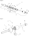
Figure 3 - is the exploded view of the exhaust outlet line in the air purifier in an embodiment of the present invention. -
Figure 4 - is the perspective view showing the state before the inner and outer parts forming the exhaust outlet line are connected in the air purifier in an embodiment of the present invention. -
Figure 5 - is the cross-sectional view showing the state after the inner and outer parts forming the exhaust outlet line are connected in the air purifier in an embodiment of the present invention. -
Figure 6 - is the view showing the connection parts of the inner and outer parts in the air purifier in an embodiment of the present invention. -
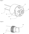
Figure 7 - is the view of the inner part in the air purifier in an embodiment of the present invention. -
Figure 8 - is the view of the outlet pipe and the duckbill provided at the outlet pipe in the air purifier in an embodiment of the present invention. -
Figure 9 - is the view of the outer part of the exhaust outlet line in the air purifier in an embodiment of the present invention. - The elements illustrated in the figures are numbered as follows:
- 1.
- Air purifier
- 2.
- Body
- 3.
- CO2 adsorption unit
- 4.
- Receptacle
- 5.
- Control unit
- 6.
- Exhaust outlet line
- 7.
- Inner part
- 8.
- Outer part
- 9.
- Inlet pipe
- 10.
- Pin
- 11.
- Pin housing
- 12.
- Locking part
- 13.
- Pushing part
- 14.
- Lid
- 15.
- Metal plate
- 16.
- Claw
- 17.
- Sealing member
- 18.
- Interconnecting part
- 19.
- Valve cap
- 20.
- Spring
- 21.
- Valve housing
- 22.
- Housing
- 23.
- Outlet pipe
- 24.
- Duckbill
- 25.
- Filter lid
- I:
- Air inlet
- O:
- Clean air outlet
- The air purifier (1) comprises a body (2) having an air inlet (I) through which air from an indoor environment is sucked and a fresh air outlet (O) through which the purified air is supplied to the environment; a CO2 adsorption unit (3) which is provided in the body (2), which can be filled with basic liquid solution and which enables the carbon dioxide in the air to be adsorbed chemically; a receptacle (4) wherein the carbon dioxide adsorbed in the carbonate form in the CO2 adsorption unit (3) is treated with an acidic solution to be released again; and an exhaust outlet line (6) which enables the carbon dioxide and other waste gases released as a result of the reaction of the carbonate solution in the receptacle (4) with the acidic solution to be discharged from the body (2) to an outer environment.
- The air purifier (1) of the present invention further comprises
- the exhaust outlet line (6) comprising an inner part (7) having an inlet pipe (9) extending from the body (2) and through which carbon dioxide and waste gases enter, a locking part (12) attached to the end of the inlet pipe (9) and at least one pin (10) extending outwards from the locking part (12) and an outer part (8) detachably attached to the inner part (7) and having an interconnecting part (18) which can be connected to the locking part (12); a metal plate (15) which is disposed on the interconnecting part (18) and with which the pin (10) can get into contact and an outlet pipe (23) which enables the waste gases to be released to the outside environment; and
- a control unit (5) which detects that the inner part (7) and the outer part (8) are connected to each other as the pin (10) gets into contact with the metal plate (15) and which accordingly starts the air purification process.
- In the air purifier of the present invention, the air of the indoor environment desired to be purified is sucked into the body (2). The air sucked into the body (2) is directly taken into the CO2 adsorption unit (3). First a basic liquid solution is fed here. The basic liquid solution can be directly provided in the CO2 adsorption unit (3) or can be fed from a base tank disposed in the body (2). In the CO2 adsorption unit (3), the carbon dioxide in the air is adsorbed by the carbonation reaction. The clean air cleansed of carbon dioxide is released back to the indoor environment through the clean air outlet (O). On the other hand, the carbonate solution is taken into a separate receptacle (4) to be treated with an acidic solution. Here, carbon dioxide and waste gases are released again. In order not to release the carbon dioxide back to the indoor environment, an exhaust outlet line (6) is opened to the outside environment. In the air purifier (1) of the present invention, the exhaust outlet line (6) has a two-piece structure and comprises an inner part (7) and an outer part (8). The inner part (7) is the part which remains inside the window or wall of the room, etc., where the air is purified. On the other hand, the outer part (8) is the part remaining outside the window and the wall, in the outer environment. The inner part (7) comprises an inlet pipe (9) which extends from the body (2) and through which carbon dioxide enters, a locking part (12) which attached to the inlet pipe (9) and at least one pin (10). The outer part (8) comprises an outlet pipe (23), an interconnecting part (18) which can be detachably connected to the locking part (12), and a metal plate (15) which is disposed on the interconnecting part (18). While the air purifier (1) is placed in front of a window, wall, etc., the inner part (7) is attached to the interconnecting part (18) by means of the locking part (12). At the same time, if a correct locking is performed, the pin (10) gets into contact with the metal plate (15) on the interconnecting part (18). Thus, the control unit (5) detects that the inner part (7) and the outer part (8) are correctly connected to each other and starts the air purification process of the air purifier (1). Otherwise, the control unit (5) does not start the air purification process and undesirable situations such as the release of waste gases to the indoor environment are prevented.
- In an embodiment of the present invention, the air purifier (1) comprises at least one claw (16) which is provided on the locking part (12) and a housing (22) which is provided on the interconnecting part (18) and which is suitable for receiving and locking the claw (16). In this embodiment, the claw (16) is fitted into the housing (22) and locked, and the locking part (12) and the interconnecting part (18) are enabled to be securely locked to each other.
- In an embodiment of the present invention, the air purifier (1) comprises the pin (10) one end of which is connected to the control unit (5) by means of a cable extending from the inlet pipe (9) and a pin housing (11) which is provided on the locking part (12) and through which the pin (10) passes while the inner part (7) and the outer part (8) are connected to each other.
- In an embodiment of the present invention, the air purifier (1) comprises a pushing part (13) which is provided on the locking part (12); a valve cap (19) which is disposed on the interconnecting part (18); a spring (20) which is fitted on the valve cap (19) so as to move the valve cap (19) towards the outlet pipe (23) by the force applied by the pushing part (13), and a valve housing (21) which connects the valve cap (19), the spring (20) and the interconnecting part (18) to the outlet pipe (23). Thus, when the inner part (7) and the outer part (8) are connected to each other, flow is provided for the passage of waste gases by pushing the valve cap (19) and the spring (20) towards the outlet pipe (23), and carbon dioxide passage is allowed from the inlet pipe (9) to the outlet pipe (23).
- In an embodiment of the present invention, the air purifier (1) comprises a sealing member (17) which is disposed between the locking part (12) and the interconnecting part (18) and which prevents the waste gases from leaking to the indoor environment.
- In an embodiment of the present invention, the air purifier (1) comprises the sealing member (17) which is disposed between the valve cap (19) and the interconnecting part (18) and which prevents the waste gases from leaking to the indoor environment.
- In an embodiment of the present invention, the air purifier (1) comprises a duckbill (24) which is disposed on the outlet pipe (23) so as to prevent foreign substances which may enter the outlet pipe (23) from the outside environment during the waste gas discharge.
- In an embodiment of the present invention, the air purifier (1) comprises a lid (14) which can be attached to the interconnecting part (18) so as to cover the interconnecting part (18) in order to prevent the entry of foreign materials into the outer part (8) before the inner part (7) and outer part (8) are connected to each other.
- In an embodiment of the present invention, the air purifier (1) comprises a filter lid (25) which is attached on the outlet pipe (23) at the outer end of the outlet pipe (23) and on the duckbill (24) and which ensures that the waste gas flow is unidirectional from the indoor environment to the outside environment.
- By means of the present invention, an air purifier (1) is realized, which does not start the air purification process until the exhaust outlet line (6) is installed correctly and which effectively purify the indoor air and discharge the waste gases to the outside environment.
Claims (9)
- An air purifier (1) comprising a body (2) having an air inlet (I) through which air from an indoor environment is sucked and a fresh air outlet (O) through which the purified air is supplied to the environment; a CO2 adsorption unit (3) which is provided in the body (2), which can be filled with basic liquid solution and which enables the carbon dioxide in the air to be adsorbed chemically; a receptacle (4) wherein the carbon dioxide adsorbed in the carbonate form in the CO2 adsorption unit (3) is treated with an acidic solution to be released again; and an exhaust outlet line (6) which enables the carbon dioxide and other waste gases released as a result of the reaction of the carbonate solution in the receptacle (4) with the acidic solution to be discharged from the body (2) to an outer environment, characterized by- the exhaust outlet line (6) comprising an inner part (7) having an inlet pipe (9) extending from the body (2) and through which carbon dioxide and waste gases enter, a locking part (12) attached to the end of the inlet pipe (9) and at least one pin (10) extending outwards from the locking part (12) and an outer part (8) detachably attached to the inner part (7) and having an interconnecting part (18) which can be connected to the locking part (12); a metal plate (15) which is disposed on the interconnecting part (18) and with which the pin (10) can get into contact and an outlet pipe (23) which enables the waste gases to be released to the outside environment; and- a control unit (5) which detects that the inner part (7) and the outer part (8) are connected to each other as the pin (10) gets into contact with the metal plate (15) and which accordingly starts the air purification process.
- An air purifier (1) as in Claim 1, characterized by at least one claw (16) which is provided on the locking part (12) and a housing (22) which is provided on the interconnecting part (18) and which is suitable for receiving and locking the claw (16).
- An air purifier (1) as in Claim 1 or 2, characterized by the pin (10) one end of which is connected to the control unit (5) by means of a cable extending from the inlet pipe (9) and a pin housing (11) which is provided on the locking part (12) and through which the pin (10) passes while the inner part (7) and the outer part (8) are connected to each other.
- An air purifier (1) as in any one of Claims 1 to 3, characterized by a pushing part (13) which is provided on the locking part (12); a valve cap (19) which is disposed on the interconnecting part (18); a spring (20) which is fitted on the valve cap (19) so as to move the valve cap (19) towards the outlet pipe (23) by the force applied by the pushing part (13), and a valve housing (21) which connects the valve cap (19), the spring (20) and the interconnecting part (18) to the outlet pipe (23).
- An air purifier (1) as in any one of Claims 1 to 4, characterized by a sealing member (17) which is disposed between the locking part (12) and the interconnecting part (18) and which prevents the waste gases from leaking to the indoor environment.
- An air purifier (1) as in Claim 4 or 5, characterized by a sealing member (17) which is disposed between the valve cap (19) and the interconnecting part (18) and which prevents the waste gases from leaking to the indoor environment.
- An air purifier (1) as in any one of the above claims, characterized by a duckbill (24) which is disposed on the outlet pipe (23) so as to prevent foreign substances which may enter the outlet pipe (23) from the outside environment during the waste gas discharge.
- An air purifier (1) as in any one of the above claims, characterized by a lid (14) which can be attached to the interconnecting part (18) so as to cover the interconnecting part (18) in order to prevent the entry of foreign materials into the outer part (8) before the inner part (7) and outer part (8) are connected to each other.
- An air purifier (1) as in any one of the above claims, characterized by a filter lid (25) which is attached on the outlet pipe (23) at the outer end of the outlet pipe (23) and on the duckbill (24) and which ensures that the waste gas flow is unidirectional from the indoor environment to the outside environment.
Applications Claiming Priority (1)
| Application Number | Priority Date | Filing Date | Title |
|---|---|---|---|
| TR202215359 | 2022-10-07 |
Publications (2)
| Publication Number | Publication Date |
|---|---|
| EP4350233A1 true EP4350233A1 (en) | 2024-04-10 |
| EP4350233B1 EP4350233B1 (en) | 2025-08-06 |
Family
ID=88236465
Family Applications (1)
| Application Number | Title | Priority Date | Filing Date |
|---|---|---|---|
| EP23200464.8A Active EP4350233B1 (en) | 2022-10-07 | 2023-09-28 | An air purifier comprising an exhaust outlet line |
Country Status (1)
| Country | Link |
|---|---|
| EP (1) | EP4350233B1 (en) |
Citations (4)
| Publication number | Priority date | Publication date | Assignee | Title |
|---|---|---|---|---|
| WO2022098326A1 (en) * | 2020-11-03 | 2022-05-12 | Arcelik Anonim Sirketi | An air purifier detecting errors |
| EP4029591A1 (en) * | 2021-01-15 | 2022-07-20 | Arçelik Anonim Sirketi | An air purifier detecting liquid level |
| EP4062999A1 (en) * | 2021-03-10 | 2022-09-28 | Arçelik Anonim Sirketi | An air purifier with increased operational speed |
| EP4067762A1 (en) * | 2021-03-30 | 2022-10-05 | Arçelik Anonim Sirketi | An air purifier detecting leaks |
-
2023
- 2023-09-28 EP EP23200464.8A patent/EP4350233B1/en active Active
Patent Citations (4)
| Publication number | Priority date | Publication date | Assignee | Title |
|---|---|---|---|---|
| WO2022098326A1 (en) * | 2020-11-03 | 2022-05-12 | Arcelik Anonim Sirketi | An air purifier detecting errors |
| EP4029591A1 (en) * | 2021-01-15 | 2022-07-20 | Arçelik Anonim Sirketi | An air purifier detecting liquid level |
| EP4062999A1 (en) * | 2021-03-10 | 2022-09-28 | Arçelik Anonim Sirketi | An air purifier with increased operational speed |
| EP4067762A1 (en) * | 2021-03-30 | 2022-10-05 | Arçelik Anonim Sirketi | An air purifier detecting leaks |
Also Published As
| Publication number | Publication date |
|---|---|
| EP4350233B1 (en) | 2025-08-06 |
Similar Documents
| Publication | Publication Date | Title |
|---|---|---|
| KR100530851B1 (en) | Apparatus for air cleaning and method for air cleaning | |
| US20010012494A1 (en) | Means of providing safe haven within buildings during chemical or biological attack | |
| CN115698599A (en) | Method and apparatus for purifying biological agents and volatile organic compounds from air | |
| WO2022050918A1 (en) | An air purifier comprising a carbon dioxide adsorption unit | |
| KR20080050552A (en) | Multifunctional Chamber for Life Protection | |
| CA2315074A1 (en) | Chemical feeder | |
| EP3842700B1 (en) | An air purifier comprising a neutralization receptacle | |
| EP4350233B1 (en) | An air purifier comprising an exhaust outlet line | |
| EP4067762B1 (en) | An air purifier detecting leaks | |
| KR20040058590A (en) | Air cleaner having air cleaning compound | |
| KR100364584B1 (en) | Oxygen supply device utilizing air segregaton film | |
| CN220062041U (en) | Emergency purifying device for filtering and humidifying smoke dust in air | |
| EP4062999A1 (en) | An air purifier with increased operational speed | |
| KR20220040799A (en) | Wet oxygen generator for antimicrobial protection with mask | |
| EP3842699A1 (en) | An air purifier wherein the hydrogen release is controlled | |
| US20090110609A1 (en) | Pressurization Device And Air Treatment System For A Shelter | |
| CN108731120A (en) | A kind of air pollution treatment purifier | |
| CN210613733U (en) | A laboratory chemical reagent safety ventilation storage cabinet | |
| CN208579437U (en) | A kind of air pollution treatment purification device | |
| TR2022015359A2 (en) | AN AIR PURIFICATION DEVICE WITH EXHAUST OUTLET LINE | |
| JP2006281025A (en) | air purifier | |
| CN216223734U (en) | Carbon dioxide neutralization purifier | |
| KR20220075869A (en) | Air purifying apparatus and system | |
| US20230221020A1 (en) | An air purifier comprising a diffuser | |
| CN211119793U (en) | an air purifier |
Legal Events
| Date | Code | Title | Description |
|---|---|---|---|
| PUAI | Public reference made under article 153(3) epc to a published international application that has entered the european phase |
Free format text: ORIGINAL CODE: 0009012 |
|
| STAA | Information on the status of an ep patent application or granted ep patent |
Free format text: STATUS: REQUEST FOR EXAMINATION WAS MADE |
|
| 17P | Request for examination filed |
Effective date: 20230928 |
|
| AK | Designated contracting states |
Kind code of ref document: A1 Designated state(s): AL AT BE BG CH CY CZ DE DK EE ES FI FR GB GR HR HU IE IS IT LI LT LU LV MC ME MK MT NL NO PL PT RO RS SE SI SK SM TR |
|
| GRAP | Despatch of communication of intention to grant a patent |
Free format text: ORIGINAL CODE: EPIDOSNIGR1 |
|
| STAA | Information on the status of an ep patent application or granted ep patent |
Free format text: STATUS: GRANT OF PATENT IS INTENDED |
|
| INTG | Intention to grant announced |
Effective date: 20250411 |
|
| GRAS | Grant fee paid |
Free format text: ORIGINAL CODE: EPIDOSNIGR3 |
|
| GRAA | (expected) grant |
Free format text: ORIGINAL CODE: 0009210 |
|
| STAA | Information on the status of an ep patent application or granted ep patent |
Free format text: STATUS: THE PATENT HAS BEEN GRANTED |
|
| AK | Designated contracting states |
Kind code of ref document: B1 Designated state(s): AL AT BE BG CH CY CZ DE DK EE ES FI FR GB GR HR HU IE IS IT LI LT LU LV MC ME MK MT NL NO PL PT RO RS SE SI SK SM TR |
|
| REG | Reference to a national code |
Ref country code: GB Ref legal event code: FG4D |
|
| REG | Reference to a national code |
Ref country code: CH Ref legal event code: EP |
|
| REG | Reference to a national code |
Ref country code: IE Ref legal event code: FG4D |
|
| REG | Reference to a national code |
Ref country code: DE Ref legal event code: R096 Ref document number: 602023005428 Country of ref document: DE |
|
| PGFP | Annual fee paid to national office [announced via postgrant information from national office to epo] |
Ref country code: AT Payment date: 20251020 Year of fee payment: 3 |
|
| REG | Reference to a national code |
Ref country code: NL Ref legal event code: MP Effective date: 20250806 |
|
| PG25 | Lapsed in a contracting state [announced via postgrant information from national office to epo] |
Ref country code: IS Free format text: LAPSE BECAUSE OF FAILURE TO SUBMIT A TRANSLATION OF THE DESCRIPTION OR TO PAY THE FEE WITHIN THE PRESCRIBED TIME-LIMIT Effective date: 20251206 |
|
| PGFP | Annual fee paid to national office [announced via postgrant information from national office to epo] |
Ref country code: DE Payment date: 20251128 Year of fee payment: 3 |
|
| PG25 | Lapsed in a contracting state [announced via postgrant information from national office to epo] |
Ref country code: NO Free format text: LAPSE BECAUSE OF FAILURE TO SUBMIT A TRANSLATION OF THE DESCRIPTION OR TO PAY THE FEE WITHIN THE PRESCRIBED TIME-LIMIT Effective date: 20251106 |
|
| REG | Reference to a national code |
Ref country code: LT Ref legal event code: MG9D |
|
| PG25 | Lapsed in a contracting state [announced via postgrant information from national office to epo] |
Ref country code: PT Free format text: LAPSE BECAUSE OF FAILURE TO SUBMIT A TRANSLATION OF THE DESCRIPTION OR TO PAY THE FEE WITHIN THE PRESCRIBED TIME-LIMIT Effective date: 20251209 |
|
| PG25 | Lapsed in a contracting state [announced via postgrant information from national office to epo] |
Ref country code: FI Free format text: LAPSE BECAUSE OF FAILURE TO SUBMIT A TRANSLATION OF THE DESCRIPTION OR TO PAY THE FEE WITHIN THE PRESCRIBED TIME-LIMIT Effective date: 20250806 |
|
| PG25 | Lapsed in a contracting state [announced via postgrant information from national office to epo] |
Ref country code: HR Free format text: LAPSE BECAUSE OF FAILURE TO SUBMIT A TRANSLATION OF THE DESCRIPTION OR TO PAY THE FEE WITHIN THE PRESCRIBED TIME-LIMIT Effective date: 20250806 Ref country code: NL Free format text: LAPSE BECAUSE OF FAILURE TO SUBMIT A TRANSLATION OF THE DESCRIPTION OR TO PAY THE FEE WITHIN THE PRESCRIBED TIME-LIMIT Effective date: 20250806 |
|
| PGFP | Annual fee paid to national office [announced via postgrant information from national office to epo] |
Ref country code: FR Payment date: 20251128 Year of fee payment: 3 |
|
| PG25 | Lapsed in a contracting state [announced via postgrant information from national office to epo] |
Ref country code: GR Free format text: LAPSE BECAUSE OF FAILURE TO SUBMIT A TRANSLATION OF THE DESCRIPTION OR TO PAY THE FEE WITHIN THE PRESCRIBED TIME-LIMIT Effective date: 20251107 |
|
| PGFP | Annual fee paid to national office [announced via postgrant information from national office to epo] |
Ref country code: TR Payment date: 20251106 Year of fee payment: 3 |
|
| PG25 | Lapsed in a contracting state [announced via postgrant information from national office to epo] |
Ref country code: SE Free format text: LAPSE BECAUSE OF FAILURE TO SUBMIT A TRANSLATION OF THE DESCRIPTION OR TO PAY THE FEE WITHIN THE PRESCRIBED TIME-LIMIT Effective date: 20250806 |
|
| PG25 | Lapsed in a contracting state [announced via postgrant information from national office to epo] |
Ref country code: LV Free format text: LAPSE BECAUSE OF FAILURE TO SUBMIT A TRANSLATION OF THE DESCRIPTION OR TO PAY THE FEE WITHIN THE PRESCRIBED TIME-LIMIT Effective date: 20250806 |
|
| PG25 | Lapsed in a contracting state [announced via postgrant information from national office to epo] |
Ref country code: PL Free format text: LAPSE BECAUSE OF FAILURE TO SUBMIT A TRANSLATION OF THE DESCRIPTION OR TO PAY THE FEE WITHIN THE PRESCRIBED TIME-LIMIT Effective date: 20250806 Ref country code: BG Free format text: LAPSE BECAUSE OF FAILURE TO SUBMIT A TRANSLATION OF THE DESCRIPTION OR TO PAY THE FEE WITHIN THE PRESCRIBED TIME-LIMIT Effective date: 20250806 |
|
| PG25 | Lapsed in a contracting state [announced via postgrant information from national office to epo] |
Ref country code: RS Free format text: LAPSE BECAUSE OF FAILURE TO SUBMIT A TRANSLATION OF THE DESCRIPTION OR TO PAY THE FEE WITHIN THE PRESCRIBED TIME-LIMIT Effective date: 20251106 |
|
| PG25 | Lapsed in a contracting state [announced via postgrant information from national office to epo] |
Ref country code: ES Free format text: LAPSE BECAUSE OF FAILURE TO SUBMIT A TRANSLATION OF THE DESCRIPTION OR TO PAY THE FEE WITHIN THE PRESCRIBED TIME-LIMIT Effective date: 20250806 |
|
| REG | Reference to a national code |
Ref country code: AT Ref legal event code: MK05 Ref document number: 1822247 Country of ref document: AT Kind code of ref document: T Effective date: 20250806 |
|
| PG25 | Lapsed in a contracting state [announced via postgrant information from national office to epo] |
Ref country code: RO Free format text: LAPSE BECAUSE OF FAILURE TO SUBMIT A TRANSLATION OF THE DESCRIPTION OR TO PAY THE FEE WITHIN THE PRESCRIBED TIME-LIMIT Effective date: 20250806 |
|
| PG25 | Lapsed in a contracting state [announced via postgrant information from national office to epo] |
Ref country code: SM Free format text: LAPSE BECAUSE OF FAILURE TO SUBMIT A TRANSLATION OF THE DESCRIPTION OR TO PAY THE FEE WITHIN THE PRESCRIBED TIME-LIMIT Effective date: 20250806 |
|
| PG25 | Lapsed in a contracting state [announced via postgrant information from national office to epo] |
Ref country code: DK Free format text: LAPSE BECAUSE OF FAILURE TO SUBMIT A TRANSLATION OF THE DESCRIPTION OR TO PAY THE FEE WITHIN THE PRESCRIBED TIME-LIMIT Effective date: 20250806 |
|
| PG25 | Lapsed in a contracting state [announced via postgrant information from national office to epo] |
Ref country code: AT Free format text: LAPSE BECAUSE OF FAILURE TO SUBMIT A TRANSLATION OF THE DESCRIPTION OR TO PAY THE FEE WITHIN THE PRESCRIBED TIME-LIMIT Effective date: 20250806 |
|
| PG25 | Lapsed in a contracting state [announced via postgrant information from national office to epo] |
Ref country code: IT Free format text: LAPSE BECAUSE OF FAILURE TO SUBMIT A TRANSLATION OF THE DESCRIPTION OR TO PAY THE FEE WITHIN THE PRESCRIBED TIME-LIMIT Effective date: 20250806 |
|
| PG25 | Lapsed in a contracting state [announced via postgrant information from national office to epo] |
Ref country code: CZ Free format text: LAPSE BECAUSE OF FAILURE TO SUBMIT A TRANSLATION OF THE DESCRIPTION OR TO PAY THE FEE WITHIN THE PRESCRIBED TIME-LIMIT Effective date: 20250806 |
|
| PG25 | Lapsed in a contracting state [announced via postgrant information from national office to epo] |
Ref country code: EE Free format text: LAPSE BECAUSE OF FAILURE TO SUBMIT A TRANSLATION OF THE DESCRIPTION OR TO PAY THE FEE WITHIN THE PRESCRIBED TIME-LIMIT Effective date: 20250806 Ref country code: SK Free format text: LAPSE BECAUSE OF FAILURE TO SUBMIT A TRANSLATION OF THE DESCRIPTION OR TO PAY THE FEE WITHIN THE PRESCRIBED TIME-LIMIT Effective date: 20250806 |
|
| REG | Reference to a national code |
Ref country code: DE Ref legal event code: R097 Ref document number: 602023005428 Country of ref document: DE |
|
| PG25 | Lapsed in a contracting state [announced via postgrant information from national office to epo] |
Ref country code: LU Free format text: LAPSE BECAUSE OF NON-PAYMENT OF DUE FEES Effective date: 20250928 |
|
| REG | Reference to a national code |
Ref country code: BE Ref legal event code: MM Effective date: 20250930 |
|
| PLBE | No opposition filed within time limit |
Free format text: ORIGINAL CODE: 0009261 |
|
| STAA | Information on the status of an ep patent application or granted ep patent |
Free format text: STATUS: NO OPPOSITION FILED WITHIN TIME LIMIT |
|
| REG | Reference to a national code |
Ref country code: CH Ref legal event code: L10 Free format text: ST27 STATUS EVENT CODE: U-0-0-L10-L00 (AS PROVIDED BY THE NATIONAL OFFICE) Effective date: 20260617 |
|
| PG25 | Lapsed in a contracting state [announced via postgrant information from national office to epo] |
Ref country code: LT Free format text: LAPSE BECAUSE OF FAILURE TO SUBMIT A TRANSLATION OF THE DESCRIPTION OR TO PAY THE FEE WITHIN THE PRESCRIBED TIME-LIMIT Effective date: 20250806 Ref country code: MC Free format text: LAPSE BECAUSE OF FAILURE TO SUBMIT A TRANSLATION OF THE DESCRIPTION OR TO PAY THE FEE WITHIN THE PRESCRIBED TIME-LIMIT Effective date: 20250806 |
|
| 26N | No opposition filed |
Effective date: 20260507 |
|
| PG25 | Lapsed in a contracting state [announced via postgrant information from national office to epo] |
Ref country code: BE Free format text: LAPSE BECAUSE OF NON-PAYMENT OF DUE FEES Effective date: 20250930 Ref country code: IE Free format text: LAPSE BECAUSE OF NON-PAYMENT OF DUE FEES Effective date: 20250928 |