EP4350196A1 - Liquid tank, rocket, and method of manufacturing liquid tank - Google Patents
Liquid tank, rocket, and method of manufacturing liquid tank Download PDFInfo
- Publication number
- EP4350196A1 EP4350196A1 EP22816151.9A EP22816151A EP4350196A1 EP 4350196 A1 EP4350196 A1 EP 4350196A1 EP 22816151 A EP22816151 A EP 22816151A EP 4350196 A1 EP4350196 A1 EP 4350196A1
- Authority
- EP
- European Patent Office
- Prior art keywords
- tank body
- baffles
- tank
- peripheral surface
- oxidant
- Prior art date
- Legal status (The legal status is an assumption and is not a legal conclusion. Google has not performed a legal analysis and makes no representation as to the accuracy of the status listed.)
- Pending
Links
Images



Classifications
-
- F—MECHANICAL ENGINEERING; LIGHTING; HEATING; WEAPONS; BLASTING
- F17—STORING OR DISTRIBUTING GASES OR LIQUIDS
- F17C—VESSELS FOR CONTAINING OR STORING COMPRESSED, LIQUEFIED OR SOLIDIFIED GASES; FIXED-CAPACITY GAS-HOLDERS; FILLING VESSELS WITH, OR DISCHARGING FROM VESSELS, COMPRESSED, LIQUEFIED, OR SOLIDIFIED GASES
- F17C13/00—Details of vessels or of the filling or discharging of vessels
- F17C13/008—Details of vessels or of the filling or discharging of vessels for use under microgravity conditions
-
- B—PERFORMING OPERATIONS; TRANSPORTING
- B21—MECHANICAL METAL-WORKING WITHOUT ESSENTIALLY REMOVING MATERIAL; PUNCHING METAL
- B21D—WORKING OR PROCESSING OF SHEET METAL OR METAL TUBES, RODS OR PROFILES WITHOUT ESSENTIALLY REMOVING MATERIAL; PUNCHING METAL
- B21D22/00—Shaping without cutting, by stamping, spinning, or deep-drawing
- B21D22/14—Spinning
-
- B—PERFORMING OPERATIONS; TRANSPORTING
- B21—MECHANICAL METAL-WORKING WITHOUT ESSENTIALLY REMOVING MATERIAL; PUNCHING METAL
- B21D—WORKING OR PROCESSING OF SHEET METAL OR METAL TUBES, RODS OR PROFILES WITHOUT ESSENTIALLY REMOVING MATERIAL; PUNCHING METAL
- B21D51/00—Making hollow objects
- B21D51/16—Making hollow objects characterised by the use of the objects
- B21D51/18—Making hollow objects characterised by the use of the objects vessels, e.g. tubs, vats, tanks, sinks, or the like
-
- B—PERFORMING OPERATIONS; TRANSPORTING
- B64—AIRCRAFT; AVIATION; COSMONAUTICS
- B64G—COSMONAUTICS; VEHICLES OR EQUIPMENT THEREFOR
- B64G1/00—Cosmonautic vehicles
- B64G1/22—Parts of, or equipment specially adapted for fitting in or to, cosmonautic vehicles
- B64G1/40—Arrangements or adaptations of propulsion systems
- B64G1/402—Propellant tanks; Feeding propellants
- B64G1/4021—Tank construction; Details thereof
-
- B—PERFORMING OPERATIONS; TRANSPORTING
- B64—AIRCRAFT; AVIATION; COSMONAUTICS
- B64G—COSMONAUTICS; VEHICLES OR EQUIPMENT THEREFOR
- B64G1/00—Cosmonautic vehicles
- B64G1/22—Parts of, or equipment specially adapted for fitting in or to, cosmonautic vehicles
- B64G1/40—Arrangements or adaptations of propulsion systems
-
- F—MECHANICAL ENGINEERING; LIGHTING; HEATING; WEAPONS; BLASTING
- F17—STORING OR DISTRIBUTING GASES OR LIQUIDS
- F17C—VESSELS FOR CONTAINING OR STORING COMPRESSED, LIQUEFIED OR SOLIDIFIED GASES; FIXED-CAPACITY GAS-HOLDERS; FILLING VESSELS WITH, OR DISCHARGING FROM VESSELS, COMPRESSED, LIQUEFIED, OR SOLIDIFIED GASES
- F17C2201/00—Vessel construction, in particular geometry, arrangement or size
- F17C2201/01—Shape
- F17C2201/0104—Shape cylindrical
- F17C2201/0109—Shape cylindrical with exteriorly curved end-piece
-
- F—MECHANICAL ENGINEERING; LIGHTING; HEATING; WEAPONS; BLASTING
- F17—STORING OR DISTRIBUTING GASES OR LIQUIDS
- F17C—VESSELS FOR CONTAINING OR STORING COMPRESSED, LIQUEFIED OR SOLIDIFIED GASES; FIXED-CAPACITY GAS-HOLDERS; FILLING VESSELS WITH, OR DISCHARGING FROM VESSELS, COMPRESSED, LIQUEFIED, OR SOLIDIFIED GASES
- F17C2201/00—Vessel construction, in particular geometry, arrangement or size
- F17C2201/05—Size
- F17C2201/054—Size medium (>1 m3)
-
- F—MECHANICAL ENGINEERING; LIGHTING; HEATING; WEAPONS; BLASTING
- F17—STORING OR DISTRIBUTING GASES OR LIQUIDS
- F17C—VESSELS FOR CONTAINING OR STORING COMPRESSED, LIQUEFIED OR SOLIDIFIED GASES; FIXED-CAPACITY GAS-HOLDERS; FILLING VESSELS WITH, OR DISCHARGING FROM VESSELS, COMPRESSED, LIQUEFIED, OR SOLIDIFIED GASES
- F17C2203/00—Vessel construction, in particular walls or details thereof
- F17C2203/01—Reinforcing or suspension means
- F17C2203/011—Reinforcing means
- F17C2203/013—Reinforcing means in the vessel, e.g. columns
-
- F—MECHANICAL ENGINEERING; LIGHTING; HEATING; WEAPONS; BLASTING
- F17—STORING OR DISTRIBUTING GASES OR LIQUIDS
- F17C—VESSELS FOR CONTAINING OR STORING COMPRESSED, LIQUEFIED OR SOLIDIFIED GASES; FIXED-CAPACITY GAS-HOLDERS; FILLING VESSELS WITH, OR DISCHARGING FROM VESSELS, COMPRESSED, LIQUEFIED, OR SOLIDIFIED GASES
- F17C2203/00—Vessel construction, in particular walls or details thereof
- F17C2203/06—Materials for walls or layers thereof; Properties or structures of walls or their materials
- F17C2203/0602—Wall structures; Special features thereof
- F17C2203/0612—Wall structures
- F17C2203/0614—Single wall
- F17C2203/0617—Single wall with one layer
-
- F—MECHANICAL ENGINEERING; LIGHTING; HEATING; WEAPONS; BLASTING
- F17—STORING OR DISTRIBUTING GASES OR LIQUIDS
- F17C—VESSELS FOR CONTAINING OR STORING COMPRESSED, LIQUEFIED OR SOLIDIFIED GASES; FIXED-CAPACITY GAS-HOLDERS; FILLING VESSELS WITH, OR DISCHARGING FROM VESSELS, COMPRESSED, LIQUEFIED, OR SOLIDIFIED GASES
- F17C2209/00—Vessel construction, in particular methods of manufacturing
- F17C2209/23—Manufacturing of particular parts or at special locations
- F17C2209/232—Manufacturing of particular parts or at special locations of walls
-
- F—MECHANICAL ENGINEERING; LIGHTING; HEATING; WEAPONS; BLASTING
- F17—STORING OR DISTRIBUTING GASES OR LIQUIDS
- F17C—VESSELS FOR CONTAINING OR STORING COMPRESSED, LIQUEFIED OR SOLIDIFIED GASES; FIXED-CAPACITY GAS-HOLDERS; FILLING VESSELS WITH, OR DISCHARGING FROM VESSELS, COMPRESSED, LIQUEFIED, OR SOLIDIFIED GASES
- F17C2221/00—Handled fluid, in particular type of fluid
- F17C2221/01—Pure fluids
- F17C2221/011—Oxygen
-
- F—MECHANICAL ENGINEERING; LIGHTING; HEATING; WEAPONS; BLASTING
- F17—STORING OR DISTRIBUTING GASES OR LIQUIDS
- F17C—VESSELS FOR CONTAINING OR STORING COMPRESSED, LIQUEFIED OR SOLIDIFIED GASES; FIXED-CAPACITY GAS-HOLDERS; FILLING VESSELS WITH, OR DISCHARGING FROM VESSELS, COMPRESSED, LIQUEFIED, OR SOLIDIFIED GASES
- F17C2221/00—Handled fluid, in particular type of fluid
- F17C2221/08—Ergols, e.g. hydrazine
-
- F—MECHANICAL ENGINEERING; LIGHTING; HEATING; WEAPONS; BLASTING
- F17—STORING OR DISTRIBUTING GASES OR LIQUIDS
- F17C—VESSELS FOR CONTAINING OR STORING COMPRESSED, LIQUEFIED OR SOLIDIFIED GASES; FIXED-CAPACITY GAS-HOLDERS; FILLING VESSELS WITH, OR DISCHARGING FROM VESSELS, COMPRESSED, LIQUEFIED, OR SOLIDIFIED GASES
- F17C2223/00—Handled fluid before transfer, i.e. state of fluid when stored in the vessel or before transfer from the vessel
- F17C2223/01—Handled fluid before transfer, i.e. state of fluid when stored in the vessel or before transfer from the vessel characterised by the phase
- F17C2223/0146—Two-phase
- F17C2223/0153—Liquefied gas, e.g. LPG, GPL
- F17C2223/0161—Liquefied gas, e.g. LPG, GPL cryogenic, e.g. LNG, GNL, PLNG
-
- F—MECHANICAL ENGINEERING; LIGHTING; HEATING; WEAPONS; BLASTING
- F17—STORING OR DISTRIBUTING GASES OR LIQUIDS
- F17C—VESSELS FOR CONTAINING OR STORING COMPRESSED, LIQUEFIED OR SOLIDIFIED GASES; FIXED-CAPACITY GAS-HOLDERS; FILLING VESSELS WITH, OR DISCHARGING FROM VESSELS, COMPRESSED, LIQUEFIED, OR SOLIDIFIED GASES
- F17C2223/00—Handled fluid before transfer, i.e. state of fluid when stored in the vessel or before transfer from the vessel
- F17C2223/03—Handled fluid before transfer, i.e. state of fluid when stored in the vessel or before transfer from the vessel characterised by the pressure level
- F17C2223/033—Small pressure, e.g. for liquefied gas
-
- F—MECHANICAL ENGINEERING; LIGHTING; HEATING; WEAPONS; BLASTING
- F17—STORING OR DISTRIBUTING GASES OR LIQUIDS
- F17C—VESSELS FOR CONTAINING OR STORING COMPRESSED, LIQUEFIED OR SOLIDIFIED GASES; FIXED-CAPACITY GAS-HOLDERS; FILLING VESSELS WITH, OR DISCHARGING FROM VESSELS, COMPRESSED, LIQUEFIED, OR SOLIDIFIED GASES
- F17C2260/00—Purposes of gas storage and gas handling
- F17C2260/01—Improving mechanical properties or manufacturing
- F17C2260/016—Preventing slosh
-
- F—MECHANICAL ENGINEERING; LIGHTING; HEATING; WEAPONS; BLASTING
- F17—STORING OR DISTRIBUTING GASES OR LIQUIDS
- F17C—VESSELS FOR CONTAINING OR STORING COMPRESSED, LIQUEFIED OR SOLIDIFIED GASES; FIXED-CAPACITY GAS-HOLDERS; FILLING VESSELS WITH, OR DISCHARGING FROM VESSELS, COMPRESSED, LIQUEFIED, OR SOLIDIFIED GASES
- F17C2270/00—Applications
- F17C2270/01—Applications for fluid transport or storage
- F17C2270/0186—Applications for fluid transport or storage in the air or in space
- F17C2270/0197—Rockets
Definitions
- the present disclosure relates to a liquid tank, a rocket, and a method of manufacturing a liquid tank.
- the present application claims the benefit of priority based on Japanese Patent Application No. 2021-92569 filed on June 1, 2021 , and the content thereof is incorporated herein by reference.
- a liquid tank that accommodates a liquid is used in various devices or various facilities.
- Patent Literature 1 there is a disclosure of a hybrid rocket including an oxidant tank that accommodates a liquid oxidant.
- Patent Literature 1 JP 2011-020880 A
- the manufacturing process may become redundant due to the presence of a seam caused by welding, bolt fastening, or the like.
- the manufacturing process of a liquid tank may tend to become redundant due to, for example, the necessity for designing in consideration of a weak point and a defect of welding.
- An object of the present disclosure is to provide a liquid tank, a rocket, and a method of manufacturing a liquid tank that enable shortening of the manufacturing process of a liquid tank.
- a liquid tank including: a cylindrical seamless tank body having both end portions being reduced in diameter toward respective end sides; and a plurality of annular baffles provided inside the tank body and arranged at intervals in an axial direction of the tank body, in which at least one of the plurality of baffles is held on an inner peripheral surface of the tank body.
- the at least one of the plurality of baffles may be clamped by the inner peripheral surface of the tank body.
- the plurality of baffles may be connected to each other by a connecting member extending in the axial direction.
- Baffles located at both ends in the axial direction among the plurality of baffles may be held on the inner peripheral surface of the tank body.
- An inclined surface inclined with respect to the axial direction may be formed on a surface other than an outer peripheral surface of the baffle held on the inner peripheral surface of the tank body among the plurality of baffles.
- the plurality of baffles may include a baffle having an outer peripheral surface spaced apart from the inner peripheral surface of the tank body.
- a rocket including the above-mentioned liquid tank.
- a method of manufacturing a liquid tank including: installing a plurality of annular baffles inside a cylindrical blank pipe at intervals in an axial direction of the blank pipe; and after installing the plurality of baffles inside the blank pipe, reducing both end portions of the blank pipe in diameter toward respective end sides to form a seamless tank body.
- a manufacturing process of the liquid tank can be shortened.
- FIG. 1 is a schematic view for illustrating a rocket 1 according to this embodiment.
- the rocket 1 is a hybrid rocket. As illustrated in FIG. 1 , the rocket 1 includes an oxidant tank 2, an injector plate 3, an engine casing 4, and a nozzle 5.
- the oxidant tank 2 corresponds to an example of a liquid tank of the present disclosure.
- the liquid tank of the present disclosure may be a liquid tank of a rocket other than a hybrid rocket, or may be a liquid tank of a device other than a rocket.
- the oxidant tank 2 accommodates an oxidant 6 that is a liquid.
- the oxidant 6 include liquid oxygen, hydrogen peroxide, nitrogen tetroxide, nitrous oxide, and the like.
- the oxidant tank 2 is connected to one end portion (left end portion in FIG. 1 ) of the cylindrical engine casing 4 through intermediation of the injector plate 3.
- the oxidant 6 accommodated in the oxidant tank 2 is jetted into the engine casing 4 from a jetting port (not shown) formed in the injector plate 3.
- a solid fuel 7 is accommodated in the engine casing 4.
- the solid fuel 7 include hydroxyl-terminated polybutadiene (HTPB), HTPB mixed with carbon black (that is, carbon fine particles), and the like.
- a through hole 8 extending in an axial direction of the engine casing 4 is formed in the solid fuel 7.
- the oxidant 6 is jetted into the engine casing 4, the solid fuel 7 is combusted.
- combustion is performed on a side wall of the through hole 8 to generate a combustion gas.
- the nozzle 5 is connected to another end portion (right end portion in FIG. 1 ) of the engine casing 4.
- the combustion gas generated within the engine casing 4 is jetted from the nozzle 5.
- the thrust of the rocket 1 is obtained.
- the configuration of the oxidant tank 2 is described below in detail with reference to FIG. 2 and FIG. 3 .
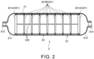
- FIG. 2 is a sectional view for illustrating the oxidant tank 2 according to this embodiment.
- FIG. 3 is an enlarged sectional view for illustrating the oxidant tank 2 according to this embodiment.
- FIG. 3 is an enlarged sectional view for illustrating a portion on a left side of FIG. 2 of the oxidant tank 2.
- the oxidant tank 2 includes a tank body 21 and a baffle structure 22.
- An axial direction of the tank body 21, a circumferential direction of the tank body 21, and a radial direction of the tank body 21 are hereinafter simply referred to as "axial direction”, "circumferential direction", and "radial direction.”
- the tank body 21 accommodates the oxidant 6 that is a liquid.
- the tank body 21 is formed in a seamless manner. That is, the tank body 21 does not have a seam caused by welding, bolt fastening, or the like.
- the shape of the tank body 21 is a cylindrical shape in which both end portions 211 and 212 are reduced in diameter toward respective end sides.
- the tank body 21 is formed by, for example, spinning as described later.
- An opening 213 is formed at a distal end of the end portion 211 (left end portion in FIG. 2 ) of the tank body 21.
- An opening 214 is formed at a distal end of the end portion 212 (right end portion in FIG. 2 ) of the tank body 21.
- Other members for example, a stopper or a pipe
- the baffle structure 22 is provided inside the tank body 21.
- the baffle structure 22 is a structure for suppressing sloshing of the oxidant 6 inside the tank body 21.
- the baffle structure 22 includes a plurality of baffles 221 and connecting members 222.
- the baffle 221 is an annular member.
- the plurality of baffles 221 are arranged at intervals in the axial direction of the tank body 21.
- the plurality of baffles 221 are arranged coaxially.
- Each of the baffles 221 extends in the circumferential direction along an inner peripheral surface F1 of the tank body 21.
- the plurality of baffles 221 are connected to each other by the connecting members 222.
- the connecting member 222 extends in the axial direction of the tank body 21.
- the connecting member 222 is a rod-shaped member.
- the sectional shape of the connecting member 222 is not particularly limited, and may be, for example, a circular shape or a polygonal shape.
- the connecting member 222 may be hollow or solid.
- the number of the connecting member 222 is not particularly limited.
- a plurality of connecting members 222 are arranged at intervals in the circumferential direction.
- the connecting members 222 penetrate through each of the baffles 221.
- a through hole extending in the axial direction is formed in a member forming each of the baffles 221, and the connecting member 222 is inserted through the through hole.
- the connecting member 222 may not penetrate through each of the baffles 221.
- Each of the baffles 221 is mounted on the connecting member 222 by, for example, welding, bolt fastening, or the like.
- the plurality of baffles 221 include end baffles 221A and normal baffles 221B.
- the end baffles 221A are the baffles 221 located at both ends in the axial direction among the plurality of baffles 221.
- the normal baffles 221B are the baffles 221 other than the end baffles 221A among the plurality of baffles 221.
- seven normal baffles 221B are provided.
- the number of the normal baffles 221B may be other than seven.
- the plurality of baffles 221 are arranged at equal intervals.
- the plurality of baffles 221 may be arranged at unequal intervals.
- the end baffle 221A is held on the inner peripheral surface F1 of the tank body 21. Specifically, the end baffle 221A is clamped by the inner peripheral surface F1 of the tank body 21. As illustrated in FIG. 3 , an outer peripheral surface F2 of the end baffle 221A is in contact with the inner peripheral surface F1 of the tank body 21. The outer peripheral surface F2 of the end baffle 221A is pressed radially inward by the inner peripheral surface F1 of the tank body 21. Thus, the holding of the end baffle 221A by the tank body 21 is achieved. Alternatively, the holding of the end baffle 221A by the tank body 21 may be achieved by a force in a direction other than the radially inward direction (for example, an axial force).
- the holding of the end baffle 221A by the tank body 21 is achieved by, for example, spinning as described later.
- the end baffle 221A is held on a portion, which extends in the axial direction, of the inner peripheral surface F1 of the tank body 21.
- the end baffle 221A may be held on a portion, which is reduced in diameter toward an end side, of the inner peripheral surface F1 of the tank body 21.
- the baffle structure 22 is held on the tank body 21 when the end baffles 221A are held on the inner peripheral surface F1 of the tank body 21.
- the end baffles 221A are provided mainly in order to cause the baffle structure 22 to be held on the tank body 21.
- an axial thickness of the end baffle 221A is larger than an axial thickness of the normal baffle 221B.
- the axial thickness of the end baffle 221A may be the same as the axial thickness of the normal baffle 221B, or may be smaller than the axial thickness of the normal baffle 221B.
- an inclined surface F3 that is inclined with respect to the axial direction is formed on a surface other than the outer peripheral surface F2 of the end baffle 221A.
- the inclined surface F3 is inclined radially inward as the incline surface F3 approaches the opening 213.
- the cleaning liquid inside the tank body 21 is smoothly discharged to the outside of the tank body 21.
- the inclined surface F3 may be inclined radially inward with distance from the opening 213. In this case, when the cleaning liquid is discharged from the opening 214 to the outside of the tank body 21, the cleaning liquid present on the opening 213 side with respect to the end baffle 221A is smoothly discharged along the inclined surface F3.
- a through hole extending in the axial direction may be formed in the end baffle 221A.
- a plurality of through holes are formed in the end baffle 221A at intervals in the circumferential direction.
- the normal baffles 221B are not held on the inner peripheral surface F1 of the tank body 21.
- the normal baffles 221B are provided inside the tank body 21, sloshing of the oxidant 6 inside the tank body 21 is suppressed.
- the normal baffles 221B are provided in order to suppress sloshing of the oxidant 6 inside the tank body 21.
- an outer peripheral surface F4 of the normal baffle 221B is spaced apart from the inner peripheral surface F1 of the tank body 21.
- a through hole extending in the axial direction may be formed in the normal baffle 221B.
- a plurality of through holes are formed in the normal baffle 221B at intervals in the circumferential direction.
- An inner diameter of the normal baffle 221B may be the same as or different from an inner diameter (that is, the minimum diameter of the inclined surface F3) of the end baffle 221A.
- the oxidant tank 2 includes the seamless tank body 21. Further, the baffle structure 22 is held on the tank body 21 when the end baffles 221A are held on the inner peripheral surface F1 of the tank body 21. With this configuration, the baffles 221 are provided inside the tank body 21 with simple structure. When there is a seam caused by welding, bolt fastening, or the like in the tank body 21, a manufacturing process of the oxidant tank 2 may tend to become redundant due to the necessity for designing in consideration of a weak point and a defect of welding, the necessity for inspection of welded portions of the oxidant tank 2, and the like.
- the tank body 21 is seamless, and the baffles 221 are provided inside the tank body 21 with simple structure.
- the designing in consideration of a weak point and a defect of welding and the inspection process of welded portions can be eliminated, with the result that the manufacturing process is shortened.
- a procurement period, manufacturing cost, and inspection cost of the oxidant tank 2 can also be reduced.
- the oxidant tank 2 can be reduced in weight as compared to the case in which there is a seam caused by welding, bolt fastening, or the like in the tank body 21. Further, safety can be enhanced. Further, sloshing can be appropriately suppressed.
- the end baffle 221A is clamped by the inner peripheral surface F1 of the tank body 21.
- the end baffle 221A may be welded to the inner peripheral surface F1 of the tank body 21.
- the end baffle 221A be clamped by the inner peripheral surface F1 of the tank body 21 as in the above-mentioned example.
- the procurement period, the manufacturing cost, and the inspection cost of the oxidant tank 2 can be further reduced.
- the oxidant tank 2 can be further reduced in weight to enhance the safety.
- the baffles 221 located at the both ends in the axial direction are held on the inner peripheral surface F1 of the tank body 21.
- one or a plurality of baffles 221 located at positions other than the both ends in the axial direction may be held on the inner peripheral surface F1 of the tank body 21.
- the plurality of baffles 221 are connected to each other by the connecting members 222.
- the connecting members 222 may be omitted from the configuration of the oxidant tank 2.
- each of the baffles 221 is held on the inner peripheral surface F1 of the tank body 21.
- the plurality of baffles 221 be connected to each other by the connecting members 222.
- FIG. 4 to FIG. 6 A method of manufacturing the oxidant tank 2 is described with reference to FIG. 4 to FIG. 6 .
- each of constituent elements is simplified as compared to those in FIG. 2 and FIG. 3 .
- the number of the normal baffles 221B in the baffle structure 22 is reduced as compared to that of FIG. 2 and FIG. 3 .
- the tank body 21 is formed by, for example, spinning.
- the baffle structure 22 is installed inside a cylindrical blank pipe 23 before spinning is performed. After that, the blank pipe 23 is subjected to spinning to form the tank body 21.
- FIG. 4 is a schematic view for illustrating a state before spinning of the blank pipe 23 of the tank body 21 in this embodiment.
- a wall thickness of a center portion 231 in the axial direction of the blank pipe 23 is smaller than a wall thickness of both end portions 232 and 233 of the blank pipe 23.
- An inner diameter of the center portion 231 is the same as an inner diameter of the both end portions 232 and 233.
- An outer diameter of the center portion 231 is smaller than an outer diameter of the both end portions 232 and 233.
- the blank pipe 23 is formed by, for example, flow forming.
- the baffle structure 22 is installed inside such blank pipe 23 so that a direction in which the plurality of baffles 221 are arranged matches the axial direction of the blank pipe 23.
- the plurality of baffles 221 are installed inside the blank pipe 23 at intervals in the axial direction of the blank pipe 23.
- An axial position of each of the end baffles 221A is in the vicinity of an axial position of a connecting portion between the center portion 231 of the blank pipe 23 and each of the end portions 232 and 233 thereof.
- the baffle structure 22 is installed through use of, for example, a jig. The jig is removed at appropriate timing during spinning.
- FIG. 5 is a schematic view for illustrating a state during spinning of the blank pipe 23 of the tank body 21 in this embodiment.
- FIG. 6 is a schematic view for illustrating a state after spinning of the blank pipe 23 of the tank body 21 in this embodiment.
- the blank pipe 23 is deformed by pressing a tool against the blank pipe 23 from a radially outer side while the blank pipe 23 is being rotated.
- the both end portions 232 and 233 of the blank pipe 23 are reduced in diameter toward respective end sides.
- the both end portions 232 and 233 of the blank pipe 23 clamp the end baffles 221A while being deformed.
- FIG. 6 there is illustrated a state in which the formation of the tank body 21 is completed, and the end baffles 221A are held on the inner peripheral surface F1 of the tank body 21. As described above, the end baffles 221A are clamped by the inner peripheral surface F1 of the tank body 21 while the seamless tank body 21 is being formed by spinning.
- the method of manufacturing the oxidant tank 2 includes installing the plurality of baffles 221 inside the cylindrical blank pipe 23 at intervals in the axial direction of the blank pipe 23. Further, the method of manufacturing the oxidant tank 2 includes, after installing the plurality of baffles 221 inside the blank pipe 23, reducing the both end portions 232 and 233 of the blank pipe 23 in diameter toward respective end sides to form the seamless tank body 21. With this configuration, the formation of the seamless tank body 21 and the provision of the plurality of baffles 221 inside the tank body 21 are appropriately achieved. Thus, the manufacturing process of the oxidant tank 2 is shortened. As a result, the procurement period, the manufacturing cost, and the inspection cost of the oxidant tank 2 can be reduced. Further, the oxidant tank 2 can be reduced in weight to enhance the safety. Further, sloshing can be appropriately suppressed.
- various steps such as heat treatment, may be added to the method of manufacturing the oxidant tank 2 described above.
- the end baffles 221A are clamped by the inner peripheral surface F1 of the tank body 21 by subjecting the blank pipe 23 to spinning.
- the end baffles 221A may be welded to the inner peripheral surface F1 of the tank body 21 as described above.
- the blank pipe 23 is prepared by flow forming.
- the blank pipe 23 may be prepared by spinning.
- both end portions 232 and 233 of the blank pipe 23 are reduced in diameter toward respective end sides by spinning.
- the both end portions 232 and 233 of the blank pipe 23 may be reduced in diameter toward respective end sides by flow forming.
- the liquid tank of the present disclosure is the oxidant tank 2 of the rocket 1 that is a hybrid rocket.
- the liquid tank of the present disclosure may be a liquid tank of a rocket other than the hybrid rocket.
- the liquid tank of the present disclosure may be an oxidant tank or fuel tank of a liquid rocket including a liquid oxidant and a liquid fuel.
- the liquid tank of the present disclosure may be a liquid tank of a device (for example, a vehicle) other than the rocket.
- the present disclosure is more effectively utilized.
- the wall thickness of the liquid tank hardly changes irrespective of the size of the rocket.
- the ratio of the weight of the liquid tank in the entire rocket becomes smaller as compared to that of a small-size or medium-size rocket.
- the ratio of the weight of the liquid tank in the entire rocket becomes larger as compared to that of the large-size rocket.
- the reduction in weight of the liquid tank is further desired.
Landscapes
- Engineering & Computer Science (AREA)
- Mechanical Engineering (AREA)
- Chemical & Material Sciences (AREA)
- Combustion & Propulsion (AREA)
- Remote Sensing (AREA)
- Aviation & Aerospace Engineering (AREA)
- General Engineering & Computer Science (AREA)
- Filling Or Discharging Of Gas Storage Vessels (AREA)
Abstract
Description
- The present disclosure relates to a liquid tank, a rocket, and a method of manufacturing a liquid tank. The present application claims the benefit of priority based on
Japanese Patent Application No. 2021-92569 filed on June 1, 2021 - A liquid tank that accommodates a liquid is used in various devices or various facilities. For example, in Patent Literature 1, there is a disclosure of a hybrid rocket including an oxidant tank that accommodates a liquid oxidant.
- Patent Literature 1:
JP 2011-020880 A - In a related-art liquid tank in various devices or various facilities, the manufacturing process may become redundant due to the presence of a seam caused by welding, bolt fastening, or the like. For example, the manufacturing process of a liquid tank may tend to become redundant due to, for example, the necessity for designing in consideration of a weak point and a defect of welding.
- An object of the present disclosure is to provide a liquid tank, a rocket, and a method of manufacturing a liquid tank that enable shortening of the manufacturing process of a liquid tank.
- In order to solve the above-mentioned problem, according to the present disclosure, there is provided a liquid tank, including: a cylindrical seamless tank body having both end portions being reduced in diameter toward respective end sides; and a plurality of annular baffles provided inside the tank body and arranged at intervals in an axial direction of the tank body, in which at least one of the plurality of baffles is held on an inner peripheral surface of the tank body.
- The at least one of the plurality of baffles may be clamped by the inner peripheral surface of the tank body.
- The plurality of baffles may be connected to each other by a connecting member extending in the axial direction.
- Baffles located at both ends in the axial direction among the plurality of baffles may be held on the inner peripheral surface of the tank body.
- An inclined surface inclined with respect to the axial direction may be formed on a surface other than an outer peripheral surface of the baffle held on the inner peripheral surface of the tank body among the plurality of baffles.
- The plurality of baffles may include a baffle having an outer peripheral surface spaced apart from the inner peripheral surface of the tank body.
- In order to solve the above-mentioned problem, according to the present disclosure, there is provided a rocket including the above-mentioned liquid tank.
- In order to solve the above-mentioned problem, according to the present disclosure, there is provided a method of manufacturing a liquid tank, including: installing a plurality of annular baffles inside a cylindrical blank pipe at intervals in an axial direction of the blank pipe; and after installing the plurality of baffles inside the blank pipe, reducing both end portions of the blank pipe in diameter toward respective end sides to form a seamless tank body.
- According to the present disclosure, a manufacturing process of the liquid tank can be shortened.
-
-
FIG. 1 is a schematic view for illustrating a rocket according to this embodiment. -
FIG. 2 is a sectional view for illustrating an oxidant tank according to this embodiment. -
FIG. 3 is an enlarged sectional view for illustrating the oxidant tank according to this embodiment. -
FIG. 4 is a schematic view for illustrating a state before spinning of a blank pipe of a tank body in this embodiment. -
FIG. 5 is a schematic view for illustrating a state during spinning of the blank pipe of the tank body in this embodiment. -
FIG. 6 is a schematic view for illustrating a state after spinning of the blank pipe of the tank body in this embodiment. - An embodiment of the present disclosure is described below with reference to the accompanying drawings. Dimensions, materials, other specific numerical values, and the like described in the embodiment are merely examples for facilitating understanding, and do not limit the present disclosure unless otherwise stated. In this Description and the drawings, elements having substantially the same functions and configurations are denoted by the same reference symbols to omit overlapping description, and elements that are not directly related to the present disclosure are not shown.
-
FIG. 1 is a schematic view for illustrating a rocket 1 according to this embodiment. The rocket 1 is a hybrid rocket. As illustrated inFIG. 1 , the rocket 1 includes anoxidant tank 2, aninjector plate 3, anengine casing 4, and anozzle 5. - The
oxidant tank 2 corresponds to an example of a liquid tank of the present disclosure. Alternatively, as described later, the liquid tank of the present disclosure may be a liquid tank of a rocket other than a hybrid rocket, or may be a liquid tank of a device other than a rocket. - The
oxidant tank 2 accommodates anoxidant 6 that is a liquid. Examples of theoxidant 6 include liquid oxygen, hydrogen peroxide, nitrogen tetroxide, nitrous oxide, and the like. Theoxidant tank 2 is connected to one end portion (left end portion inFIG. 1 ) of thecylindrical engine casing 4 through intermediation of theinjector plate 3. Theoxidant 6 accommodated in theoxidant tank 2 is jetted into theengine casing 4 from a jetting port (not shown) formed in theinjector plate 3. - A
solid fuel 7 is accommodated in theengine casing 4. Examples of thesolid fuel 7 include hydroxyl-terminated polybutadiene (HTPB), HTPB mixed with carbon black (that is, carbon fine particles), and the like. A throughhole 8 extending in an axial direction of theengine casing 4 is formed in thesolid fuel 7. When theoxidant 6 is jetted into theengine casing 4, thesolid fuel 7 is combusted. Specifically, when theoxidant 6 flows through the throughhole 8 of thesolid fuel 7, combustion is performed on a side wall of the throughhole 8 to generate a combustion gas. - The
nozzle 5 is connected to another end portion (right end portion inFIG. 1 ) of theengine casing 4. The combustion gas generated within theengine casing 4 is jetted from thenozzle 5. Thus, the thrust of the rocket 1 is obtained. - The configuration of the
oxidant tank 2 is described below in detail with reference toFIG. 2 andFIG. 3 . -
FIG. 2 is a sectional view for illustrating theoxidant tank 2 according to this embodiment.FIG. 3 is an enlarged sectional view for illustrating theoxidant tank 2 according to this embodiment.FIG. 3 is an enlarged sectional view for illustrating a portion on a left side ofFIG. 2 of theoxidant tank 2. As illustrated inFIG. 2 , theoxidant tank 2 includes atank body 21 and abaffle structure 22. An axial direction of thetank body 21, a circumferential direction of thetank body 21, and a radial direction of thetank body 21 are hereinafter simply referred to as "axial direction", "circumferential direction", and "radial direction." - The
tank body 21 accommodates theoxidant 6 that is a liquid. Thetank body 21 is formed in a seamless manner. That is, thetank body 21 does not have a seam caused by welding, bolt fastening, or the like. The shape of thetank body 21 is a cylindrical shape in which bothend portions tank body 21 is formed by, for example, spinning as described later. - An
opening 213 is formed at a distal end of the end portion 211 (left end portion inFIG. 2 ) of thetank body 21. Anopening 214 is formed at a distal end of the end portion 212 (right end portion inFIG. 2 ) of thetank body 21. Other members (for example, a stopper or a pipe) are connected to theopenings - The
baffle structure 22 is provided inside thetank body 21. Thebaffle structure 22 is a structure for suppressing sloshing of theoxidant 6 inside thetank body 21. Thebaffle structure 22 includes a plurality ofbaffles 221 and connectingmembers 222. - The
baffle 221 is an annular member. The plurality ofbaffles 221 are arranged at intervals in the axial direction of thetank body 21. The plurality ofbaffles 221 are arranged coaxially. Each of thebaffles 221 extends in the circumferential direction along an inner peripheral surface F1 of thetank body 21. The plurality ofbaffles 221 are connected to each other by the connectingmembers 222. - The connecting
member 222 extends in the axial direction of thetank body 21. The connectingmember 222 is a rod-shaped member. The sectional shape of the connectingmember 222 is not particularly limited, and may be, for example, a circular shape or a polygonal shape. The connectingmember 222 may be hollow or solid. The number of the connectingmember 222 is not particularly limited. For example, a plurality of connectingmembers 222 are arranged at intervals in the circumferential direction. In the example ofFIG. 2 andFIG. 3 , the connectingmembers 222 penetrate through each of thebaffles 221. Specifically, a through hole extending in the axial direction is formed in a member forming each of thebaffles 221, and the connectingmember 222 is inserted through the through hole. Alternatively, the connectingmember 222 may not penetrate through each of thebaffles 221. Each of thebaffles 221 is mounted on the connectingmember 222 by, for example, welding, bolt fastening, or the like. - The plurality of
baffles 221 include end baffles 221A andnormal baffles 221B. The end baffles 221A are thebaffles 221 located at both ends in the axial direction among the plurality ofbaffles 221. Thenormal baffles 221B are thebaffles 221 other than the end baffles 221A among the plurality ofbaffles 221. In the example ofFIG. 2 , sevennormal baffles 221B are provided. Alternatively, the number of thenormal baffles 221B may be other than seven. In the example ofFIG. 2 , the plurality ofbaffles 221 are arranged at equal intervals. Alternatively, the plurality ofbaffles 221 may be arranged at unequal intervals. - The
end baffle 221A is held on the inner peripheral surface F1 of thetank body 21. Specifically, theend baffle 221A is clamped by the inner peripheral surface F1 of thetank body 21. As illustrated inFIG. 3 , an outer peripheral surface F2 of theend baffle 221A is in contact with the inner peripheral surface F1 of thetank body 21. The outer peripheral surface F2 of theend baffle 221A is pressed radially inward by the inner peripheral surface F1 of thetank body 21. Thus, the holding of theend baffle 221A by thetank body 21 is achieved. Alternatively, the holding of theend baffle 221A by thetank body 21 may be achieved by a force in a direction other than the radially inward direction (for example, an axial force). The holding of theend baffle 221A by thetank body 21 is achieved by, for example, spinning as described later. In the example ofFIG. 2 andFIG. 3 , theend baffle 221A is held on a portion, which extends in the axial direction, of the inner peripheral surface F1 of thetank body 21. Alternatively, theend baffle 221A may be held on a portion, which is reduced in diameter toward an end side, of the inner peripheral surface F1 of thetank body 21. - The
baffle structure 22 is held on thetank body 21 when the end baffles 221A are held on the inner peripheral surface F1 of thetank body 21. Thus, the end baffles 221A are provided mainly in order to cause thebaffle structure 22 to be held on thetank body 21. From the viewpoint of increasing the strength of theend baffle 221A, an axial thickness of theend baffle 221A is larger than an axial thickness of thenormal baffle 221B. Alternatively, the axial thickness of theend baffle 221A may be the same as the axial thickness of thenormal baffle 221B, or may be smaller than the axial thickness of thenormal baffle 221B. - As illustrated in
FIG. 3 , an inclined surface F3 that is inclined with respect to the axial direction is formed on a surface other than the outer peripheral surface F2 of theend baffle 221A. In the example ofFIG. 3 , the inclined surface F3 is inclined radially inward as the incline surface F3 approaches theopening 213. With this configuration, when the inside of thetank body 21 is cleaned with a cleaning liquid, and the cleaning liquid is discharged from theopening 213 to the outside of thetank body 21, the cleaning liquid present on theopening 214 side with respect to theend baffle 221A is smoothly discharged along the inclined surface F3. Thus, the cleaning liquid inside thetank body 21 is prevented from being dammed up by theend baffle 221A to remain inside thetank body 21. As a result, the cleaning liquid inside thetank body 21 is smoothly discharged to the outside of thetank body 21. Alternatively, the inclined surface F3 may be inclined radially inward with distance from theopening 213. In this case, when the cleaning liquid is discharged from theopening 214 to the outside of thetank body 21, the cleaning liquid present on theopening 213 side with respect to theend baffle 221A is smoothly discharged along the inclined surface F3. - A through hole extending in the axial direction may be formed in the
end baffle 221A. For example, a plurality of through holes are formed in theend baffle 221A at intervals in the circumferential direction. With this configuration, when the inside of thetank body 21 is cleaned with a cleaning liquid, and the cleaning liquid is discharged from theopening 213 or theopening 214 to the outside of thetank body 21, the cleaning liquid inside thetank body 21 passes through the through holes formed in theend baffle 221A to be smoothly discharged. Thus, the cleaning liquid inside thetank body 21 is prevented from being dammed up by theend baffle 221A to remain inside thetank body 21. As a result, the cleaning liquid inside thetank body 21 is smoothly discharged to the outside of thetank body 21. - The
normal baffles 221B are not held on the inner peripheral surface F1 of thetank body 21. When thenormal baffles 221B are provided inside thetank body 21, sloshing of theoxidant 6 inside thetank body 21 is suppressed. Specifically, when a liquid surface of theoxidant 6 inside thetank body 21 fluctuates, the liquid surface of theoxidant 6 collides with thenormal baffle 221B, thereby suppressing sloshing. Thus, thenormal baffles 221B are provided in order to suppress sloshing of theoxidant 6 inside thetank body 21. - As illustrated in
FIG. 3 , an outer peripheral surface F4 of thenormal baffle 221B is spaced apart from the inner peripheral surface F1 of thetank body 21. With this configuration, when the inside of thetank body 21 is cleaned with a cleaning liquid, and the cleaning liquid is discharged from theopening 213 or theopening 214 to the outside of thetank body 21, the cleaning liquid inside thetank body 21 passes through a region between the outer peripheral surface F4 of thenormal baffle 221B and the inner peripheral surface F1 of thetank body 21 to be smoothly discharged. Thus, the cleaning liquid inside thetank body 21 is prevented from being dammed up by thenormal baffle 221B to remain inside thetank body 21. As a result, the cleaning liquid inside thetank body 21 is smoothly discharged to the outside of thetank body 21. - A through hole extending in the axial direction may be formed in the
normal baffle 221B. For example, a plurality of through holes are formed in thenormal baffle 221B at intervals in the circumferential direction. With this configuration, when the inside of thetank body 21 is cleaned with a cleaning liquid, and the cleaning liquid is discharged from theopening 213 or theopening 214 to the outside of thetank body 21, the cleaning liquid inside thetank body 21 passes through the through holes formed in thenormal baffle 221B to be smoothly discharged. Thus, the cleaning liquid inside thetank body 21 is prevented from being dammed up by thenormal baffle 221B to remain inside thetank body 21. As a result, the cleaning liquid inside thetank body 21 is smoothly discharged to the outside of thetank body 21. - An inner diameter of the
normal baffle 221B may be the same as or different from an inner diameter (that is, the minimum diameter of the inclined surface F3) of theend baffle 221A. - As described above, the
oxidant tank 2 according to this embodiment includes theseamless tank body 21. Further, thebaffle structure 22 is held on thetank body 21 when the end baffles 221A are held on the inner peripheral surface F1 of thetank body 21. With this configuration, thebaffles 221 are provided inside thetank body 21 with simple structure. When there is a seam caused by welding, bolt fastening, or the like in thetank body 21, a manufacturing process of theoxidant tank 2 may tend to become redundant due to the necessity for designing in consideration of a weak point and a defect of welding, the necessity for inspection of welded portions of theoxidant tank 2, and the like. Meanwhile, in theoxidant tank 2 according to this embodiment, thetank body 21 is seamless, and thebaffles 221 are provided inside thetank body 21 with simple structure. Thus, the designing in consideration of a weak point and a defect of welding and the inspection process of welded portions can be eliminated, with the result that the manufacturing process is shortened. With this configuration, a procurement period, manufacturing cost, and inspection cost of theoxidant tank 2 can also be reduced. Further, theoxidant tank 2 can be reduced in weight as compared to the case in which there is a seam caused by welding, bolt fastening, or the like in thetank body 21. Further, safety can be enhanced. Further, sloshing can be appropriately suppressed. - In the above-mentioned example, the
end baffle 221A is clamped by the inner peripheral surface F1 of thetank body 21. Alternatively, theend baffle 221A may be welded to the inner peripheral surface F1 of thetank body 21. However, from the viewpoint of reducing the welded portions in theoxidant tank 2 to further shorten the manufacturing process of theoxidant tank 2, it is preferred that theend baffle 221A be clamped by the inner peripheral surface F1 of thetank body 21 as in the above-mentioned example. As a result, the procurement period, the manufacturing cost, and the inspection cost of theoxidant tank 2 can be further reduced. Further, theoxidant tank 2 can be further reduced in weight to enhance the safety. - In the above-mentioned example, among the plurality of
baffles 221, thebaffles 221 located at the both ends in the axial direction (that is, the end baffles 221A) are held on the inner peripheral surface F1 of thetank body 21. In this case, it is only required that at least one of the plurality ofbaffles 221 be held on the inner peripheral surface F1 of thetank body 21. For example, among the plurality ofbaffles 221, one or a plurality ofbaffles 221 located at positions other than the both ends in the axial direction may be held on the inner peripheral surface F1 of thetank body 21. - In the above-mentioned example, the plurality of
baffles 221 are connected to each other by the connectingmembers 222. Alternatively, the connectingmembers 222 may be omitted from the configuration of theoxidant tank 2. In this case, each of thebaffles 221 is held on the inner peripheral surface F1 of thetank body 21. However, from the viewpoint of reducing the portions (for example, welded portions) on which thebaffles 221 are held in theoxidant tank 2, it is preferred that the plurality ofbaffles 221 be connected to each other by the connectingmembers 222. In particular, when the end baffles 221A (that is, thebaffles 221 located at the both ends in the axial direction of the plurality of baffles 221) are held on the inner peripheral surface F1 of thetank body 21, and thebaffle structure 22 is held on thetank body 21, the portions (for example, welded portions) on which thebaffles 221 are held in theoxidant tank 2 are effectively reduced. - A method of manufacturing the
oxidant tank 2 is described with reference toFIG. 4 to FIG. 6 . InFIG. 4 to FIG. 6 , for ease of understanding, each of constituent elements is simplified as compared to those inFIG. 2 andFIG. 3 . For example, the number of thenormal baffles 221B in thebaffle structure 22 is reduced as compared to that ofFIG. 2 andFIG. 3 . - As described above, the
tank body 21 is formed by, for example, spinning. Thebaffle structure 22 is installed inside a cylindricalblank pipe 23 before spinning is performed. After that, theblank pipe 23 is subjected to spinning to form thetank body 21. -
FIG. 4 is a schematic view for illustrating a state before spinning of theblank pipe 23 of thetank body 21 in this embodiment. As illustrated inFIG. 4 , a wall thickness of acenter portion 231 in the axial direction of theblank pipe 23 is smaller than a wall thickness of bothend portions blank pipe 23. An inner diameter of thecenter portion 231 is the same as an inner diameter of the bothend portions center portion 231 is smaller than an outer diameter of the bothend portions blank pipe 23 is formed by, for example, flow forming. Thebaffle structure 22 is installed inside suchblank pipe 23 so that a direction in which the plurality ofbaffles 221 are arranged matches the axial direction of theblank pipe 23. Thus, the plurality ofbaffles 221 are installed inside theblank pipe 23 at intervals in the axial direction of theblank pipe 23. An axial position of each of the end baffles 221A is in the vicinity of an axial position of a connecting portion between thecenter portion 231 of theblank pipe 23 and each of theend portions baffle structure 22 is installed through use of, for example, a jig. The jig is removed at appropriate timing during spinning. -
FIG. 5 is a schematic view for illustrating a state during spinning of theblank pipe 23 of thetank body 21 in this embodiment.FIG. 6 is a schematic view for illustrating a state after spinning of theblank pipe 23 of thetank body 21 in this embodiment. In spinning of theblank pipe 23, theblank pipe 23 is deformed by pressing a tool against theblank pipe 23 from a radially outer side while theblank pipe 23 is being rotated. Specifically, as illustrated inFIG. 5 , in spinning of theblank pipe 23, the bothend portions blank pipe 23 are reduced in diameter toward respective end sides. Thus, the bothend portions blank pipe 23 clamp the end baffles 221A while being deformed. InFIG. 6 , there is illustrated a state in which the formation of thetank body 21 is completed, and the end baffles 221A are held on the inner peripheral surface F1 of thetank body 21. As described above, the end baffles 221A are clamped by the inner peripheral surface F1 of thetank body 21 while theseamless tank body 21 is being formed by spinning. - As described above, the method of manufacturing the
oxidant tank 2 includes installing the plurality ofbaffles 221 inside the cylindricalblank pipe 23 at intervals in the axial direction of theblank pipe 23. Further, the method of manufacturing theoxidant tank 2 includes, after installing the plurality ofbaffles 221 inside theblank pipe 23, reducing the bothend portions blank pipe 23 in diameter toward respective end sides to form theseamless tank body 21. With this configuration, the formation of theseamless tank body 21 and the provision of the plurality ofbaffles 221 inside thetank body 21 are appropriately achieved. Thus, the manufacturing process of theoxidant tank 2 is shortened. As a result, the procurement period, the manufacturing cost, and the inspection cost of theoxidant tank 2 can be reduced. Further, theoxidant tank 2 can be reduced in weight to enhance the safety. Further, sloshing can be appropriately suppressed. - In actuality, various steps, such as heat treatment, may be added to the method of manufacturing the
oxidant tank 2 described above. In addition, in the method of manufacturing theoxidant tank 2 described above, the end baffles 221A are clamped by the inner peripheral surface F1 of thetank body 21 by subjecting theblank pipe 23 to spinning. Alternatively, the end baffles 221A may be welded to the inner peripheral surface F1 of thetank body 21 as described above. In addition, in the method of manufacturing theoxidant tank 2 described above, theblank pipe 23 is prepared by flow forming. Alternatively, theblank pipe 23 may be prepared by spinning. In addition, in the method of manufacturing theoxidant tank 2 described above, the bothend portions blank pipe 23 are reduced in diameter toward respective end sides by spinning. Alternatively, the bothend portions blank pipe 23 may be reduced in diameter toward respective end sides by flow forming. - Although the embodiment of the present disclosure has been described above with reference to the accompanying drawings, needless to say, the present disclosure is not limited to such embodiment. It is apparent that a person skilled in the art would be conceived of various modification examples or correction examples within the scope of the claims, and it is understood that these examples also inevitably belong to the technical scope of the present disclosure.
- In the foregoing, description has been given of an example in which the liquid tank of the present disclosure is the
oxidant tank 2 of the rocket 1 that is a hybrid rocket. Alternatively, the liquid tank of the present disclosure may be a liquid tank of a rocket other than the hybrid rocket. For example, the liquid tank of the present disclosure may be an oxidant tank or fuel tank of a liquid rocket including a liquid oxidant and a liquid fuel. In addition, the liquid tank of the present disclosure may be a liquid tank of a device (for example, a vehicle) other than the rocket. - In this case, when the size of the rocket in which the liquid tank of the present disclosure is used is smaller, the present disclosure is more effectively utilized. The wall thickness of the liquid tank hardly changes irrespective of the size of the rocket. Thus, in a large-size rocket, the ratio of the weight of the liquid tank in the entire rocket becomes smaller as compared to that of a small-size or medium-size rocket. Meanwhile, in the small-size or medium-size rocket, the ratio of the weight of the liquid tank in the entire rocket becomes larger as compared to that of the large-size rocket. Thus, in the small-size or medium-size rocket, the reduction in weight of the liquid tank is further desired.
- 1: rocket, 2: oxidant tank (liquid tank), 21: tank body, 23: blank pipe, 211: end portion, 212: end portion, 221: baffle, 221A: end baffle, 221B: normal baffle, 222: connecting member, 232: end portion, 233: end portion, F1: inner peripheral surface, F2: outer peripheral surface, F3: inclined surface, F4: outer peripheral surface
Claims (8)
- A liquid tank, comprising:a cylindrical seamless tank body having both end portions being reduced in diameter toward respective end sides; anda plurality of annular baffles provided inside the tank body and arranged at intervals in an axial direction of the tank body, in which at least one of the plurality of baffles is held on an inner peripheral surface of the tank body.
- The liquid tank according to claim 1, wherein the at least one of the plurality of baffles is clamped by the inner peripheral surface of the tank body.
- The liquid tank according to claim 1 or 2, wherein the plurality of baffles are connected to each other by a connecting member extending in the axial direction.
- The liquid tank according to claim 3, wherein baffles located at both ends in the axial direction among the plurality of baffles are held on the inner peripheral surface of the tank body.
- The liquid tank according to any one of claims 1 to 4, wherein an inclined surface inclined with respect to the axial direction is formed on a surface other than an outer peripheral surface of the baffle held on the inner peripheral surface of the tank body among the plurality of baffles.
- The liquid tank according to any one of claims 1 to 5, wherein the plurality of baffles include a baffle having an outer peripheral surface spaced apart from the inner peripheral surface of the tank body.
- A rocket comprising the liquid tank of any one of claims 1 to 6.
- A method of manufacturing a liquid tank, comprising:installing a plurality of annular baffles inside a cylindrical blank pipe at intervals in an axial direction of the blank pipe; andafter installing the plurality of baffles inside the blank pipe, reducing both end portions of the blank pipe in diameter toward respective end sides to form a seamless tank body.
Applications Claiming Priority (2)
| Application Number | Priority Date | Filing Date | Title |
|---|---|---|---|
| JP2021092569 | 2021-06-01 | ||
| PCT/JP2022/022288 WO2022255405A1 (en) | 2021-06-01 | 2022-06-01 | Liquid tank, rocket, and method of manufacturing liquid tank |
Publications (2)
| Publication Number | Publication Date |
|---|---|
| EP4350196A1 true EP4350196A1 (en) | 2024-04-10 |
| EP4350196A4 EP4350196A4 (en) | 2025-05-07 |
Family
ID=84324155
Family Applications (1)
| Application Number | Title | Priority Date | Filing Date |
|---|---|---|---|
| EP22816151.9A Pending EP4350196A4 (en) | 2021-06-01 | 2022-06-01 | LIQUID TANK, ROCKET AND METHOD FOR MANUFACTURING A LIQUID TANK |
Country Status (4)
| Country | Link |
|---|---|
| US (1) | US12618523B2 (en) |
| EP (1) | EP4350196A4 (en) |
| JP (1) | JP7644432B2 (en) |
| WO (1) | WO2022255405A1 (en) |
Families Citing this family (3)
| Publication number | Priority date | Publication date | Assignee | Title |
|---|---|---|---|---|
| US12214911B2 (en) * | 2021-08-03 | 2025-02-04 | The Boeing Compnay | Load coupling attachment systems and methods |
| JP2023142362A (en) * | 2022-03-25 | 2023-10-05 | サムテック株式会社 | Containers and container manufacturing methods |
| US12578058B2 (en) * | 2022-11-25 | 2026-03-17 | H2CREO Corp. | Liquid hydrogen fuel tank and liquid hydrogen storage device including same |
Family Cites Families (17)
| Publication number | Priority date | Publication date | Assignee | Title |
|---|---|---|---|---|
| US2379126A (en) * | 1943-05-11 | 1945-06-26 | Glenn L Martin Co | Surge plate |
| US2552119A (en) * | 1946-04-04 | 1951-05-08 | Goodrich Co B F | Collapsible fuel tank for aircraft |
| US7431756B2 (en) * | 2002-05-09 | 2008-10-07 | Ovonic Hydrogen Systems Llc | Modular metal hydride hydrogen storage system |
| US20060145022A1 (en) * | 2004-12-10 | 2006-07-06 | Buehler David B | Propellant tank baffle system |
| JP5666105B2 (en) | 2009-07-15 | 2015-02-12 | 株式会社Ihiエアロスペース | Hybrid rocket solid fuel |
| JP5509429B2 (en) * | 2010-03-04 | 2014-06-04 | 独立行政法人 宇宙航空研究開発機構 | Propellant tank and steam injection device using the propellant tank |
| US9683700B2 (en) * | 2014-05-20 | 2017-06-20 | Steelhead Composites, Llc. | Metallic liner pressure vessel comprising polar boss |
| DE102015002708B3 (en) | 2014-09-09 | 2015-10-22 | Mt Aerospace Ag | Containers for receiving and storing liquids and viscous substances, in particular cryogenic fluids, and process for its preparation and its use |
| CN204805946U (en) * | 2015-04-15 | 2015-11-25 | 石家庄安瑞科气体机械有限公司 | Solid -state high pressure mixes hydrogen storage apparatus |
| WO2016172430A1 (en) * | 2015-04-22 | 2016-10-27 | Keystone Engineering Company | Center of mass control of liquid tanks for spacecraft use |
| TWI804010B (en) | 2015-08-03 | 2023-06-01 | 瑞士商諾華公司 | Gdf-15 as a haematological toxicity biomarker |
| JP6553661B2 (en) * | 2016-01-27 | 2019-07-31 | 株式会社旭製作所 | Seamless container, manufacturing method thereof, composite container, and manufacturing method thereof |
| US10065751B2 (en) | 2016-04-05 | 2018-09-04 | Orbital Atk, Inc. | Liquid storage tanks and systems and propulsion systems for space vehicles and related methods |
| EP3348822B1 (en) * | 2017-01-13 | 2020-04-01 | Orbital Express Launch Limited | Rocket propellant tank arrangement, rocket propulsion unit, and rocket |
| JP6762409B2 (en) | 2019-08-07 | 2020-09-30 | Eneos株式会社 | Pressure cycle test method for composite vessels |
| US12059953B2 (en) * | 2021-02-17 | 2024-08-13 | The Boeing Company | Composite tanks for reusable launch vehicles and methods of fabricating thereof |
| FR3120678B1 (en) * | 2021-03-10 | 2023-12-08 | Faurecia Systemes Dechappement | High pressure gas tank |
-
2022
- 2022-06-01 JP JP2023525890A patent/JP7644432B2/en active Active
- 2022-06-01 EP EP22816151.9A patent/EP4350196A4/en active Pending
- 2022-06-01 WO PCT/JP2022/022288 patent/WO2022255405A1/en not_active Ceased
-
2023
- 2023-11-29 US US18/523,093 patent/US12618523B2/en active Active
Also Published As
| Publication number | Publication date |
|---|---|
| JP7644432B2 (en) | 2025-03-12 |
| US12618523B2 (en) | 2026-05-05 |
| WO2022255405A1 (en) | 2022-12-08 |
| US20240102614A1 (en) | 2024-03-28 |
| JPWO2022255405A1 (en) | 2022-12-08 |
| EP4350196A4 (en) | 2025-05-07 |
Similar Documents
| Publication | Publication Date | Title |
|---|---|---|
| US12618523B2 (en) | Liquid tank, rocket, and method of manufacturing liquid tank | |
| EP2072799B1 (en) | Connection head structure of high pressure fuel injection tube | |
| US11355764B2 (en) | Device for removing residual hydrogen in fuel cell | |
| US7774936B2 (en) | Catalytic converter and associated method of assembly | |
| EP1837597A2 (en) | Burner for combustion chamber and combustion method | |
| US20020100160A1 (en) | Fuel inlet and manufacturing method thereof | |
| CN101533920B (en) | Hydrogen discharge system for fuel cell system | |
| JP2010084700A (en) | Exhaust emission control device and method for manufacturing the exhaust emission control device | |
| EP4290102A1 (en) | High-pressure hydrogen vessel | |
| JP4894295B2 (en) | Combustion device, combustion method of combustion device, and modification method of combustion device | |
| CN108374708B (en) | Mixing tube for treating vehicle exhaust | |
| EP2028066B1 (en) | Tubular gas generator housing for an airbag | |
| EP3530898A1 (en) | Exhaust system | |
| US20020071791A1 (en) | Catalytic converter | |
| EP1457737B1 (en) | Gas turbine engine combustor | |
| JPH09150637A (en) | Fuel inlet and its manufacturing method | |
| KR102123859B1 (en) | Manufacturing method of high pressure fuel injection tube | |
| JP2024078265A (en) | Fastening structure, rocket, and method for manufacturing cylindrical member | |
| CN109869219B (en) | Housing connection element | |
| JP2005194996A (en) | Connecting method of exhaust pipe | |
| CN222756546U (en) | Columnar gas generator air guide assembly | |
| US12104512B2 (en) | Muffler and method for making the same | |
| CN217887479U (en) | Detachable palladium membrane filter element assembly | |
| CN215489783U (en) | Multi-channel gas introduction device and combustion device using the same | |
| KR20250059677A (en) | Urea supply module |
Legal Events
| Date | Code | Title | Description |
|---|---|---|---|
| STAA | Information on the status of an ep patent application or granted ep patent |
Free format text: STATUS: THE INTERNATIONAL PUBLICATION HAS BEEN MADE |
|
| PUAI | Public reference made under article 153(3) epc to a published international application that has entered the european phase |
Free format text: ORIGINAL CODE: 0009012 |
|
| STAA | Information on the status of an ep patent application or granted ep patent |
Free format text: STATUS: REQUEST FOR EXAMINATION WAS MADE |
|
| 17P | Request for examination filed |
Effective date: 20231206 |
|
| AK | Designated contracting states |
Kind code of ref document: A1 Designated state(s): AL AT BE BG CH CY CZ DE DK EE ES FI FR GB GR HR HU IE IS IT LI LT LU LV MC MK MT NL NO PL PT RO RS SE SI SK SM TR |
|
| DAV | Request for validation of the european patent (deleted) | ||
| DAX | Request for extension of the european patent (deleted) | ||
| A4 | Supplementary search report drawn up and despatched |
Effective date: 20250404 |
|
| RIC1 | Information provided on ipc code assigned before grant |
Ipc: F17C 13/00 20060101ALI20250331BHEP Ipc: B64G 1/40 20060101ALI20250331BHEP Ipc: B21D 22/14 20060101ALI20250331BHEP Ipc: F17C 1/00 20060101AFI20250331BHEP |
|
| GRAP | Despatch of communication of intention to grant a patent |
Free format text: ORIGINAL CODE: EPIDOSNIGR1 |
|
| STAA | Information on the status of an ep patent application or granted ep patent |
Free format text: STATUS: GRANT OF PATENT IS INTENDED |
|
| INTG | Intention to grant announced |
Effective date: 20260402 |