EP4350127A1 - Flange and assembly for gas turbine engine case - Google Patents
Flange and assembly for gas turbine engine case Download PDFInfo
- Publication number
- EP4350127A1 EP4350127A1 EP23201454.8A EP23201454A EP4350127A1 EP 4350127 A1 EP4350127 A1 EP 4350127A1 EP 23201454 A EP23201454 A EP 23201454A EP 4350127 A1 EP4350127 A1 EP 4350127A1
- Authority
- EP
- European Patent Office
- Prior art keywords
- flange
- segment
- circumferential
- duct
- stiffener support
- Prior art date
- Legal status (The legal status is an assumption and is not a legal conclusion. Google has not performed a legal analysis and makes no representation as to the accuracy of the status listed.)
- Pending
Links
Images





Classifications
-
- F—MECHANICAL ENGINEERING; LIGHTING; HEATING; WEAPONS; BLASTING
- F01—MACHINES OR ENGINES IN GENERAL; ENGINE PLANTS IN GENERAL; STEAM ENGINES
- F01D—NON-POSITIVE DISPLACEMENT MACHINES OR ENGINES, e.g. STEAM TURBINES
- F01D25/00—Component parts, details, or accessories, not provided for in, or of interest apart from, other groups
- F01D25/24—Casings; Casing parts, e.g. diaphragms, casing fastenings
- F01D25/243—Flange connections; Bolting arrangements
-
- F—MECHANICAL ENGINEERING; LIGHTING; HEATING; WEAPONS; BLASTING
- F01—MACHINES OR ENGINES IN GENERAL; ENGINE PLANTS IN GENERAL; STEAM ENGINES
- F01D—NON-POSITIVE DISPLACEMENT MACHINES OR ENGINES, e.g. STEAM TURBINES
- F01D21/00—Shutting-down of machines or engines, e.g. in emergency; Regulating, controlling, or safety means not otherwise provided for
- F01D21/04—Shutting-down of machines or engines, e.g. in emergency; Regulating, controlling, or safety means not otherwise provided for responsive to undesired position of rotor relative to stator or to breaking-off of a part of the rotor, e.g. indicating such position
- F01D21/045—Shutting-down of machines or engines, e.g. in emergency; Regulating, controlling, or safety means not otherwise provided for responsive to undesired position of rotor relative to stator or to breaking-off of a part of the rotor, e.g. indicating such position special arrangements in stators or in rotors dealing with breaking-off of part of rotor
-
- F—MECHANICAL ENGINEERING; LIGHTING; HEATING; WEAPONS; BLASTING
- F01—MACHINES OR ENGINES IN GENERAL; ENGINE PLANTS IN GENERAL; STEAM ENGINES
- F01D—NON-POSITIVE DISPLACEMENT MACHINES OR ENGINES, e.g. STEAM TURBINES
- F01D25/00—Component parts, details, or accessories, not provided for in, or of interest apart from, other groups
- F01D25/24—Casings; Casing parts, e.g. diaphragms, casing fastenings
-
- F—MECHANICAL ENGINEERING; LIGHTING; HEATING; WEAPONS; BLASTING
- F01—MACHINES OR ENGINES IN GENERAL; ENGINE PLANTS IN GENERAL; STEAM ENGINES
- F01D—NON-POSITIVE DISPLACEMENT MACHINES OR ENGINES, e.g. STEAM TURBINES
- F01D25/00—Component parts, details, or accessories, not provided for in, or of interest apart from, other groups
- F01D25/28—Supporting or mounting arrangements, e.g. for turbine casing
-
- F—MECHANICAL ENGINEERING; LIGHTING; HEATING; WEAPONS; BLASTING
- F01—MACHINES OR ENGINES IN GENERAL; ENGINE PLANTS IN GENERAL; STEAM ENGINES
- F01D—NON-POSITIVE DISPLACEMENT MACHINES OR ENGINES, e.g. STEAM TURBINES
- F01D25/00—Component parts, details, or accessories, not provided for in, or of interest apart from, other groups
- F01D25/28—Supporting or mounting arrangements, e.g. for turbine casing
- F01D25/285—Temporary support structures, e.g. for testing, assembling, installing, repairing; Assembly methods using such structures
-
- F—MECHANICAL ENGINEERING; LIGHTING; HEATING; WEAPONS; BLASTING
- F05—INDEXING SCHEMES RELATING TO ENGINES OR PUMPS IN VARIOUS SUBCLASSES OF CLASSES F01-F04
- F05D—INDEXING SCHEME FOR ASPECTS RELATING TO NON-POSITIVE-DISPLACEMENT MACHINES OR ENGINES, GAS-TURBINES OR JET-PROPULSION PLANTS
- F05D2220/00—Application
- F05D2220/30—Application in turbines
- F05D2220/32—Application in turbines in gas turbines
- F05D2220/323—Application in turbines in gas turbines for aircraft propulsion, e.g. jet engines
-
- F—MECHANICAL ENGINEERING; LIGHTING; HEATING; WEAPONS; BLASTING
- F05—INDEXING SCHEMES RELATING TO ENGINES OR PUMPS IN VARIOUS SUBCLASSES OF CLASSES F01-F04
- F05D—INDEXING SCHEME FOR ASPECTS RELATING TO NON-POSITIVE-DISPLACEMENT MACHINES OR ENGINES, GAS-TURBINES OR JET-PROPULSION PLANTS
- F05D2230/00—Manufacture
- F05D2230/60—Assembly methods
-
- F—MECHANICAL ENGINEERING; LIGHTING; HEATING; WEAPONS; BLASTING
- F05—INDEXING SCHEMES RELATING TO ENGINES OR PUMPS IN VARIOUS SUBCLASSES OF CLASSES F01-F04
- F05D—INDEXING SCHEME FOR ASPECTS RELATING TO NON-POSITIVE-DISPLACEMENT MACHINES OR ENGINES, GAS-TURBINES OR JET-PROPULSION PLANTS
- F05D2240/00—Components
- F05D2240/10—Stators
- F05D2240/12—Fluid guiding means, e.g. vanes
-
- F—MECHANICAL ENGINEERING; LIGHTING; HEATING; WEAPONS; BLASTING
- F05—INDEXING SCHEMES RELATING TO ENGINES OR PUMPS IN VARIOUS SUBCLASSES OF CLASSES F01-F04
- F05D—INDEXING SCHEME FOR ASPECTS RELATING TO NON-POSITIVE-DISPLACEMENT MACHINES OR ENGINES, GAS-TURBINES OR JET-PROPULSION PLANTS
- F05D2240/00—Components
- F05D2240/10—Stators
- F05D2240/14—Casings or housings protecting or supporting assemblies within
-
- F—MECHANICAL ENGINEERING; LIGHTING; HEATING; WEAPONS; BLASTING
- F05—INDEXING SCHEMES RELATING TO ENGINES OR PUMPS IN VARIOUS SUBCLASSES OF CLASSES F01-F04
- F05D—INDEXING SCHEME FOR ASPECTS RELATING TO NON-POSITIVE-DISPLACEMENT MACHINES OR ENGINES, GAS-TURBINES OR JET-PROPULSION PLANTS
- F05D2250/00—Geometry
- F05D2250/70—Shape
-
- F—MECHANICAL ENGINEERING; LIGHTING; HEATING; WEAPONS; BLASTING
- F05—INDEXING SCHEMES RELATING TO ENGINES OR PUMPS IN VARIOUS SUBCLASSES OF CLASSES F01-F04
- F05D—INDEXING SCHEME FOR ASPECTS RELATING TO NON-POSITIVE-DISPLACEMENT MACHINES OR ENGINES, GAS-TURBINES OR JET-PROPULSION PLANTS
- F05D2300/00—Materials; Properties thereof
- F05D2300/60—Properties or characteristics given to material by treatment or manufacturing
- F05D2300/603—Composites; e.g. fibre-reinforced
Definitions
- This disclosure relates to a gas turbine engine, and more particularly to gas turbine engine components having flanges.
- Gas turbine engines can include a fan for propulsion air and to cool components.
- the fan also delivers air into a core engine where it is compressed.
- the compressed air is then delivered into a combustion section, where it is mixed with fuel and ignited.
- the combustion gas expands downstream over and drives turbine blades.
- Static vanes are positioned adjacent to the turbine blades to control the flow of the products of combustion.
- the engine typically includes one or more ducts that convey airflow through a gas path of the engine.
- Some ducts may be made of a composite material and may have one more flanges for mounting the duct to another component.
- a flange stiffener support for a duct in a gas turbine engine includes a circumferential flange segment that has a plurality of flange fastener openings.
- An axial body segment extends from a radially inner side of the circumferential segment and has at least one body fastener opening. The axial body segment extends at least partially along a circumferential distance of the circumferential flange segment.
- a flange fillet segment extends from the radially inner side of the circumferential flange segment with an axial length less than an axial length of the axial body segment.
- the flange fillet segment is circumferentially spaced from the axial segment.
- the axial length of the axial body segment is greater than a radial height of the circumferential segment.
- the circumferential segment, the axial body segment, and the flange fillet segment form a single unitary piece.
- the flange fillet segment extends axially aft of an aft most surface on the circumferential segment.
- the circumferential flange segment includes one of a protrusion or a channel.
- the axial body segment and flange fillet segment each include the other of the protrusion or the channel.
- the axial body segment abuts a circumferential end of the flange fillet segment.
- each of the protrusion and the channel include a lengthwise direction that extends circumferentially with the circumferential segment.
- axial body segment extends a first circumferential distance.
- the flange fillet segment extends a second circumferential distance different from the first circumferential distance.
- a circumferential end of the axial body segment abuts a circumferential end of the flange fillet segment and a longitudinal axis of the at least one fastener body opening extends substantially perpendicular to a longitudinal axis the plurality of fastener openings in the circumferential segment.
- the protrusion includes one of a dovetail profile or an arcuate profile.
- the protrusion includes a fir tree profile.
- a gas turbine engine including a fan section and a compressor section.
- a turbine section drives the fan section and the compressor section.
- a duct assembly includes a first duct including a main body and a first flange.
- the first duct is made of a composite material.
- a second duct include a main body and a second flange.
- a flange stiffener support engaging the first flange including a circumferential flange segment having a plurality of fastener opening.
- An axial body segment extends from a radially inner side of the circumferential segment having at least one body fastener opening. The axial body axial segment extends at least partially along a circumferential distance of the circumferential flange segment.
- the gas turbine engine further comprises a flange fillet segment extending from the radially inner side of the circumferential flange segment with an axial length less than an axial length of the axial body segment, wherein the flange fillet segment is circumferentially spaced from the axial segment.
- the axial length of the axial body segment is greater than a radial height of the circumferential segment.
- an interface ring abutting the first flange and the second flange.
- the circumferential segment includes one of a projection or a channel.
- the axial body segment and flange fillet segment include the other of the projection or the channel.
- a method of assembling a duct for a gas turbine engine includes identifying a defect in a composite duct adjacent a first flange.
- a flange stiffener support is selected for engaging the first flange.
- the flange stiffener support includes a circumferential flange segment having a plurality of fastener openings for securing to the first flange.
- An axial body segment is aligned with the defect and attached to a body portion of the composite duct.
- the method further comprises selecting the flange stiffener support includes slidably engaging the axially extending portion with the circumferential flange segment of the flange stiffener support.
- the circumferential flange segment includes one of a protrusion or a channel.
- the axial body segment includes the other of the protrusion or the channel.
- a gas turbine engine 10 includes a fan section 11, a compressor section 12, a combustor section 13, and a turbine section 14. Air entering into the fan section 11 is initially compressed and fed to the compressor section 12. In the compressor section 12, the incoming air from the fan section 11 is further compressed and communicated to the combustor section 13. In the combustor section 13, the compressed air is mixed with gas and ignited to generate a hot exhaust stream E. The hot exhaust stream E is expanded through the turbine section 14 to drive the fan section 11 and the compressor section 12. The exhaust gasses E flow from the turbine section 14 through an exhaust liner assembly 18.
- the engine 10 includes one or more ducts 19 arranged about an engine central longitudinal axis A.
- the ducts 19 are dimensioned to bound a gas path of the engine 10, such as through the fan, compressor, and turbine sections 11, 12, 14 and the exhaust liner assembly 18.
- the engine 10 includes a first duct 19-1 that bounds a portion of the gas path through the fan section 11.
- the duct 19-1 includes a pair of duct halves (indicated at 19-1A, 19-1B) that establish a "split" duct circumferentially distributed and arranged in an array about the longitudinal axis A to bound the gas path.
- FIG. 1B schematically illustrates a gas turbine engine 20.
- the gas turbine engine 20 is disclosed herein as a two-spool turbofan that generally incorporates a fan section 22, a compressor section 24, a combustor section 26 and a turbine section 28.
- the fan section 22 drives air along a bypass flow path B in a bypass duct defined within a housing 15, such as a fan case or nacelle, and also drives air along a core flow path C for compression and communication into the combustor section 26 then expansion through the turbine section 28.
- the exemplary engine 20 generally includes a low speed spool 30 and a high speed spool 32 mounted for rotation about an engine central longitudinal axis A relative to an engine static structure 36 via several bearing systems 38. It should be understood that various bearing systems 38 at various locations may alternatively or additionally be provided, and the location of bearing systems 38 may be varied as appropriate to the application.
- the low speed spool 30 generally includes an inner shaft 40 that interconnects, a first (or low) pressure compressor 44 and a first (or low) pressure turbine 46.
- the inner shaft 40 is connected to the fan 42 through a speed change mechanism, which in exemplary gas turbine engine 20 is illustrated as a geared architecture 48 to drive a fan 42 at a lower speed than the low speed spool 30.
- the high speed spool 32 includes an outer shaft 50 that interconnects a second (or high) pressure compressor 52 and a second (or high) pressure turbine 54.
- a combustor 56 is arranged in exemplary gas turbine 20 between the high pressure compressor 52 and the high pressure turbine 54.
- a mid-turbine frame 57 of the engine static structure 36 may be arranged generally between the high pressure turbine 54 and the low pressure turbine 46.
- the mid-turbine frame 57 further supports bearing systems 38 in the turbine section 28.
- the inner shaft 40 and the outer shaft 50 are concentric and rotate via bearing systems 38 about the engine central longitudinal axis A which is colline
- the core airflow is compressed by the low pressure compressor 44 then the high pressure compressor 52, mixed and burned with fuel in the combustor 56, then expanded over the high pressure turbine 54 and low pressure turbine 46.
- the mid-turbine frame 57 includes airfoils 59 which are in the core airflow path C.
- the turbines 46, 54 rotationally drive the respective low speed spool 30 and high speed spool 32 in response to the expansion.
- gear system 48 may be located aft of the low pressure compressor, or aft of the combustor section 26 or even aft of turbine section 28, and fan 42 may be positioned forward or aft of the location of gear system 48.
- the engine 20 in one example is a high-bypass geared aircraft engine.
- the engine 20 bypass ratio is greater than about six (6), with an example embodiment being greater than about ten (10)
- the geared architecture 48 is an epicyclic gear train, such as a planetary gear system or other gear system, with a gear reduction ratio of greater than about 2.3
- the low pressure turbine 46 has a pressure ratio that is greater than about five.
- the engine 20 bypass ratio is greater than about ten (10:1)
- the fan diameter is significantly larger than that of the low pressure compressor 44
- the low pressure turbine 46 has a pressure ratio that is greater than about five 5:1.
- Low pressure turbine 46 pressure ratio is pressure measured prior to inlet of low pressure turbine 46 as related to the pressure at the outlet of the low pressure turbine 46 prior to an exhaust nozzle.
- the geared architecture 48 may be an epicycle gear train, such as a planetary gear system or other gear system, with a gear reduction ratio of greater than about 2.3:1 and less than about 5:1. It should be understood, however, that the above parameters are only exemplary of one embodiment of a geared architecture engine and that the present disclosure is applicable to other gas turbine engines including direct drive turbofans.
- the fan section 22 of the engine 20 is designed for a particular flight condition -- typically cruise at about 0.8 Mach and about 35,000 feet (10,668 meters).
- the flight condition of 0.8 Mach and 35,000 ft (10,668 meters), with the engine at its best fuel consumption - also known as "bucket cruise Thrust Specific Fuel Consumption ('TSFC')" - is the industry standard parameter of lbm of fuel being burned divided by lbf of thrust the engine produces at that minimum point.
- "Low fan pressure ratio” is the pressure ratio across the fan blade alone, without a Fan Exit Guide Vane (“FEGV”) system.
- the low fan pressure ratio as disclosed herein according to one non-limiting embodiment is less than about 1.45.
- the "Low corrected fan tip speed” as disclosed herein according to one non-limiting embodiment is less than about 1150 ft / second (350.5 meters/second).
- the engine 20 includes one or more ducts 23 arranged about the engine central longitudinal axis A.
- the ducts 23 are dimensioned to bound a gas path of the engine 20, such as the bypass flow path B through the fan section 22 and the core flow path C through the compressor and turbine sections 24, 28.
- Each duct 23 can include one or more flanges 23F dimensioned to mount the duct 23 to another component, such as another one of the ducts 23, or a nacelle or cowling.
- a first duct 23-1 establishes at least a portion of the housing 15.
- the first duct 23-1 bounds a flow path through the fan section 22, such as the bypass flow path B.
- the duct 23-1 includes a pair of duct halves (indicated at 23-1A, 23-1B) arranged about the longitudinal axis A. Another one of the ducts 23-2 can be incorporated in a turbine exhaust case (TEC) of the turbine section 28, for example.
- TEC turbine exhaust case
- Figures 2-3 illustrate an exemplary assembly 60 for a gas turbine engine.
- the assembly 60 can be incorporated into a portion of the gas turbine engines 10, 20 such as one of the ducts 19, 23, for example.
- the disclosed examples primarily refer to ducts, other gas turbine engine components and other systems can benefit from teachings disclosed herein, including composite casings and other structures having a flanged interface and systems lacking a fan for propulsion.
- the assembly 60 includes a first gas turbine engine component 62 and a second gas turbine engine component 64.
- the assembly 60 is a duct assembly
- the first component 62 is a first duct
- the second component 64 is a second duct.
- Each duct 62, 64 can be a split duct including a pair of duct halves circumferentially distributed and arranged in an array about a longitudinal axis to bound a gas path, as illustrated by the duct 19 of Figure 1A .
- the first and second components 62, 64 are fixedly attached or otherwise secured at a flanged interface 66.
- the first component 62 includes a first main (or duct) body 68 and a first flange 70.
- the second component 64 includes a second main (or duct) body 72 and a second flange 74.
- the main bodies 68, 72 of the first and second components 62, 64 extend along and about a longitudinal axis AA and cooperate to bound a gas path GP ( Figure 3 ).
- the longitudinal axis AA can be collinear with or parallel to with the engine longitudinal axis A of the engines 10, 20.
- the first and second flanges 70, 74 are arcuate or ring-shaped and are dimensioned to follow a circumference 69, 73 of the respective main bodies 68, 72 to at least partially or completely extend about the longitudinal axis AA to bound respective portions of the gas path GP.
- the assembly 60 includes at least one interface ring 76 trapped or positioned between the flanges 70, 74.
- the interface ring 76 is dimensioned to extend at least partially or completely about the longitudinal axis AA. However, the interface ring 76 is not required.
- the interface ring 76 is a stiffener ring 78 trapped or positioned between the flanges 70, 74.
- the stiffener ring 78 can serve to provide increased rigidity and reduced deflection of the flanges 70, 74 along the flanged interface 66.
- the stiffener ring 78 can also serve to provide support for radial stiffening members of shaft bearings.
- the assembly 60 includes at least one flange stiffener support 80 outward of the first flange 70.
- the flange stiffener support 80 is arranged such that the first flange 70 is trapped between the flange stiffener support 80 and the interface ring 76.
- the assembly 60 includes one or more fasteners F that fixedly attach the flanges 70, 74 to the interface ring 76.
- Example fasteners include bolts, screws, clips, pins and rivets.
- the fasteners F are bolts that mate with respective nuts.
- At least one fastener F extends through respective bores in the interface/stiffener ring 76/78 to fixedly attach the flanges 70, 74, as illustrated in Figure 3 .
- the main bodies 68, 72 extend in an axial (or first direction) X relative to the longitudinal axis AA.
- the main bodies 68, 72 extend in a circumferential (or second) direction T relative to the longitudinal axis AA, as illustrated in Figure 2 .
- the first flange 70 is an "upturned" flange that extends outwardly in a radial (or third) direction R from the first main body 68 at a first junction (or elbow) 82.
- the second flange 74 extends outwardly in the radial direction R from the second main body 72 at a second junction (or elbow) 84.
- the flanges 70, 74 extend in the circumferential direction T about the longitudinal axis AA, as illustrated in Figure 2 . It should be understood that the components 62, 64 including the respective flanges 70, 74 can be arranged at other orientations relative to the axes X, T and/or R in view of the teachings disclosed herein.
- the flanges 70, 74 can be dimensioned to extend radially inwardly in the radial direction R from the respective main bodies 68, 72 to establish the flanged interface 66.
- the flanges 70, 74 are dimensioned to extend axially parallel along the respective main bodies 68, 72 relative to the longitudinal axis AA.
- the first and second junctions 82, 84 can have various geometries or profiles.
- the geometry of the first and second junctions 82, 84 can be the same or can differ.
- the first junction 82 has a substantially arcuate geometry or profile with a corner filler 82A to create a substantially perpendicular profile at a radially inner side of the junction.
- the corner filler 82A includes ply layers that only extend in the region of the corner filler 82A and not along a length of the main body 68.
- the second junction 84 has a substantially perpendicular geometry or profile.
- substantially means ⁇ 10% of the disclosed relationship or value unless otherwise stated.
- first and second components 62, 64 can be utilized to form each of the first and second components 62, 64, interface/stiffener ring 76/78 and flange stiffener support 80.
- the first and/or second components 62, 64 including the first and second flanges 70, 74 can be made of metallic materials such as steel, nickel, aluminum and alloys or can be non-metallic materials such monolithic ceramics and composites including any of the composite materials disclosed herein.
- the first component 62 is a composite duct made of a composite layup CL.
- the composite layup CL includes a plurality of ply layers PL in stacked relationship that follow a contour 83 of the first junction 82 to establish at least a portion of the first main body 68 and the first flange 70.
- the component 62 is radiused along the contour 83 such that the junction 82 has a substantially arcuate profile, as illustrated in Figure 3 .
- the contour 83 defines a concave (or inner) face 85 and a convex (or outer) face 87 on opposed sides of the junction 82 that mates with the corner filler 82A.
- the faces 85, 87 of the junction 82 establish a substantially smooth transition between surfaces of the main body 68 and the first flange 70.
- one of the ply layers PL extends along the concave face 85 and another one of the ply layers PL extends along the convex face 87, and the ply layers PL are arranged such that the flange 70 is substantially perpendicular to the main body 68.
- the ply layers CL can be arranged to establish an intermediate portion 86 interconnecting the first main body 68 and the first junction 82.
- the ply layers PL are arranged such that the ply layers PL slope radially inwardly from the first main body 68 in the radial direction R towards an adjacent portion of the first junction 82 with respect to the longitudinal axis AA, as illustrated in Figure 3 .
- the ply layers CL are arranged in the stacked relationship to establish a generally J-shaped cross-sectional geometry including the first junction 82.
- the arrangement of ply layers PL along the intermediate portion 86 establishes a depression DP extending in the circumferential direction T about the circumference 69 of the first component 62.
- the composite layup CL can be constructed from continuous and/or discontinuous fibers arranged in various orientations and in one or more ply layers PL based on structural requirements.
- Example fiber materials include, but are not limited to, fiberglass, an aramid such as Kevlar ® , a ceramic such as Nextel TM , and a polyethylene such as Spectra ® .
- the ply layers PL can be constructed from uni-tape plies having a plurality of fibers oriented in the same direction or can be constructed from a two-dimensional and/or three-dimensional network of fibers, which can be woven or interlaced.
- the network of fibers can be formed from a dry fiber preform, or can be formed from a pre-impregnated (“prepreg") fabric or tape having fibers pre-impregnated with resin in a matrix, for example.
- prepreg pre-impregnated
- the fibers are infused with resin in a matrix subsequent to laying up the ply layers PL on a layup tool.
- the composite layup CL is made of an organic matric composites (OMC) or a ceramic matrix composites (CMC) including fibers in a matrix material.
- OMC organic matric composites
- CMC ceramic matrix composites
- One or more coatings can be applied to surfaces of the composite layup CL.
- the interface ring 76 can be dimensioned such that the first flange 70 sits on or is otherwise supported by the interface ring 76 along an axial face of the first flange 70.
- the interface ring 76 includes a flat mate face 77 having a constant axial dimension that mates with the first flange 70 and the corner filler 82A.
- the flange stiffener support 80 includes a circumferential flange segment 80S with a flange fillet segment 80C and an axial body segment 80A both located adjacent a radially inner diameter of the circumferential flange segment 80S.
- the circumferential flange segment 80S includes an axially upstream surface 81F that directly contacts the first flange 70 and a plurality of fastener openings 90S for accepting a fastener that extends through the first flange 70.
- the flange fillet segment 80C includes a flange fillet surface 81C that engages the concave face 85 on the main body 68.
- the flange fillet segment 80C also extends lengthwise in a circumferential direction to follow an outer contour of the main body 68 of first duct 62.
- the flange fillet surface 81C is dimensioned to substantially follow or complement the concave face 85 of the contour 83 such that the flange fillet surface 81C is opposed to the mate face 77 of the interface ring 76 on the opposite side of the first flange 70.
- the flange fillet segment 80C includes an axially aft most surface 81C2 that is axially downstream from an aft most surface of flange fillet segment 80C.
- One feature of this configuration is a greater contact area with the first duct 62 for load transfers.
- the axial body segment 80A includes a radially inward facing surface 81A that is dimensioned to substantially follow or complement the concave face 85 of the contour 83.
- the radially inward facing surface 81A is opposed to the mate face 77 of the interface ring 76 on the opposite side of the first flange 70 in a first region and a flow path, such as the core flow path or the bypass flow path B, in a second region.
- the axial body segment 80A also includes fastener openings 90A adjacent a distal end for accepting a fastener F extending through the main body 68 of the first duct 62.
- the fastener openings 90A are located in a distal 50% of the axial body segment 80A and in another example, the fastener openings are located in a distal 25% of the axial body segment 80A. Additionally, in the illustrated example, an axial length of the axial body segment 80A is greater than a radial height of the circumferential flange segment 80S. Also, the axial body segment 80A is circumferentially offset from the flange fillet segment 80C relative to the same circumferential flange segment 80S.
- fasteners F create a load path through the first flange 70, into the flange stiffener support 80, and through the fasteners F to the main body 68 of the first duct 62 to bypass defects in the duct 72 adjacent the first flange 70 as will be discussed in greater detail below.
- a longitudinal axis of the fastener openings 90A is substantially perpendicular to a longitudinal axis of the fastener openings 90S.
- flange stiffener supports 80 are arranged together to follow the first flange 70 about a circumference of the duct 62 as shown in Figure 2 .
- At least one of the flange stiffener supports 80 includes the axial body segment 80A with or without the flange fillet segment 80C.
- the inclusion of the flange fillet segment 80C with the axial body segment 80A on a single flange stiffener support 80 depends on the size and location of a defect D ( See Figure 3 ) in the duct relative to the flange stiffener support 80.
- an amount of radial variation in the axial direction can vary depending on a size of the depressed portion DP.
- radial or radially, circumference or circumferentially, and axial or axially is relative to one of the axes A or AA unless stated otherwise.
- the axial body segment 80A only extends along a portion of the circumferential width of the flange stiffener support 80. In one example, the axial body segment 80A extends less than half the circumferential width of the flange stiffener support 80. In another example, the axial body segment 80A extends at least 50% and up to 100% of the circumferential width of the flange stiffener support 80. Additionally, while the illustrated example shows the axial body segment 80A located adjacent a circumferential end of the circumferential flange segment 80S, the axial body segment 80A could be located circumferentially inward from opposing circumferential ends of the circumferential flange segment 80S. This would allow separate flange fillet segments 80C to separate the axial body segment 80A from the opposing circumferential ends of the flange stiffener support 80.
- One feature of the flange stiffener support 80 is improved reinforcement of the main body 68 in the region of the first flange 70.
- the first junction 82 and/or the main body 68 of the first duct 62 to include defects D in the ply layers PL from manufacturing that reduces the strength of the first duct 62 adjacent the first flange 70. If the defects D exceed predetermined criteria, such as size and location, the entire duct 62 might need to be discarded at a substantial financial loss and timing delay. Because the axial body segment 80A extends axially past the first junction 82 and is fastened to the main body 68 with the fasteners F, a load path through the first flange 70 will bypass the defects D and extend to the main body 68. This can reduce the number of ducts 62 in the field that need to be replaced as the first junction 82 is also a region that experiences damage during use.
- this flange stiffener support 80 can also repair ducts 62 that might otherwise be found unrepairable.
- the defect D could extend entirely through the main body 68 of the first duct. The defect D could then be patched or filled with the area of the defect then strengthened by the axial body segment 80A being circumferentially and axially aligned with an exterior of the defect D.
- Figures 6-11 illustrate another example assembly 160 with a flange stiffener support 180 similar to the flange stiffener support 80 except where described below or shown in the Figures. Like or similar features between the flange stiffener support 80 and the flange stiffener support 180 will be identified with a leading "1.”
- the flange stiffener support 180 includes a circumferential flange segment 180S, at least one axial body segment 180A, and at least one flange fillet segment 180C circumferentially offset from the at least one axial body segment 180A. Both the axial body segment 180A and the flange fillet segment 180C circumferentially overlap with the circumferential flange segment 180S. However, the axial body segment 180A could extend an entire circumferential width of the circumferential flange segment 180S without a flange fillet segment 180C.
- the circumferential flange segment 180S includes a channel 192 that extends along a radially inner side of the circumferential flange segment 180S.
- the channel 192 also extends circumferentially in a lengthwise direction to follow an outer contour of the main body 68 of the first duct 62.
- the channel 192 is configured to mate with a protrusion (or ridge) 194 on a radially outer edge of the flange fillet segment 180C or the axial body segment 180A.
- the protrusion (or ridge) 194 also extends circumferentially in a lengthwise direction to follow an outer contour of the main body 68 of the first duct 62 and the channel 192.
- Interfacing ledges are also located on oppose sides of the channel 192 and protrusion (or ridge) 194 to prevent rotational movement of the circumferential flange segment 180S relative to the axial and flange fillet segments 180A, 180C.
- One feature of having the channel 192 and protrusion (or ridge) 194 is to allow the axial body segment 180A and the flange fillet segment 180C to engage by sliding in a circumferential direction relative to the circumferential flange segment with relative movement there between in the circumferential direction (See Figure 11 ).
- This also provides improved customization of the location of the axial body segment 180A relative to the main body 68 of the first duct 62 without needed to manufacture a specific part that only provides a single configuration. For example, as shown in Figures 10-11 , multiple flange fillet segments 180C with different circumferential widths can mate with the circumferential flange segment 180S. Similarly, axial body segments 180A with different circumferential widths could also mate with the flange fillet segment 180C.
- the protrusion (or ridge) 194 are located on the axial body segment 180A and the flange fillet segment 180C to mate with the channel 192 on the circumferential flange segment 180S in the illustrated example, the channel 192 could be located on the axial body segment 180A and the flange fillet segment 180C with the protrusion (or ridge) 194 located on the circumferential flange segment 180S.
- the channel 192 and protrusion (or ridge)s 194 have complementary semicircular shapes, but other complementary shapes could be used for the channel 192 and the protrusion (or ridge)s 194.
- the circumferential flange segment 180S could include a channel 192A and the flange fillet segment 180C and the axial body segment 180A each include a complementary protrusion 194A having a dovetail profile.
- the circumferential flange segment 180S could include a channel 192B and the flange fillet segment 180C and the axial body segment 180A each include a complementary protrusion 194B having a fir tree profile defined by a triangular profile having a number of protrusions on sides adjacent a distal tip of the triangular profile.
- the channel 192 and the protrusion (or ridge) 194 follow complementary arcuate profiles that allow either the flange fillet segment 180C or the axial body segment 180A to slide into and out of engagement with the circumferential flange segment 180S.
- One feature of the ability to select a position of the axially extending portion 180E and the flange fillet segment 180C is the ability to customize the flange stiffener support 180 to any specific damage or defects D in the plies P of the duct 62 without requiring a custom machined part or maintaining a large supply of replacement parts. Additionally, if only one of the circumferential flange segment 180S, axial body segment 180A, or flange fillet segment 180C become damaged or worn, only the damaged or worn components needs to be replaced.
Landscapes
- Engineering & Computer Science (AREA)
- Mechanical Engineering (AREA)
- General Engineering & Computer Science (AREA)
- Structures Of Non-Positive Displacement Pumps (AREA)
Abstract
Description
- This disclosure relates to a gas turbine engine, and more particularly to gas turbine engine components having flanges.
- Gas turbine engines can include a fan for propulsion air and to cool components. The fan also delivers air into a core engine where it is compressed. The compressed air is then delivered into a combustion section, where it is mixed with fuel and ignited. The combustion gas expands downstream over and drives turbine blades. Static vanes are positioned adjacent to the turbine blades to control the flow of the products of combustion.
- The engine typically includes one or more ducts that convey airflow through a gas path of the engine. Some ducts may be made of a composite material and may have one more flanges for mounting the duct to another component.
- In a first aspect, there is provided a flange stiffener support for a duct in a gas turbine engine includes a circumferential flange segment that has a plurality of flange fastener openings. An axial body segment extends from a radially inner side of the circumferential segment and has at least one body fastener opening. The axial body segment extends at least partially along a circumferential distance of the circumferential flange segment.
- In an embodiment of the above, a flange fillet segment extends from the radially inner side of the circumferential flange segment with an axial length less than an axial length of the axial body segment. The flange fillet segment is circumferentially spaced from the axial segment.
- In another embodiment according to any of the previous embodiments, the axial length of the axial body segment is greater than a radial height of the circumferential segment.
- In another embodiment according to any of the previous embodiments, the circumferential segment, the axial body segment, and the flange fillet segment form a single unitary piece.
- In another embodiment according to any of the previous embodiments, the flange fillet segment extends axially aft of an aft most surface on the circumferential segment.
- In another embodiment according to any of the previous embodiments, the circumferential flange segment includes one of a protrusion or a channel. The axial body segment and flange fillet segment each include the other of the protrusion or the channel.
- In another embodiment according to any of the previous embodiments, the axial body segment abuts a circumferential end of the flange fillet segment.
- In another embodiment according to any of the previous embodiments, each of the protrusion and the channel include a lengthwise direction that extends circumferentially with the circumferential segment.
- In another embodiment according to any of the previous embodiments, axial body segment extends a first circumferential distance. The flange fillet segment extends a second circumferential distance different from the first circumferential distance.
- In another embodiment according to any of the previous embodiments, a circumferential end of the axial body segment abuts a circumferential end of the flange fillet segment and a longitudinal axis of the at least one fastener body opening extends substantially perpendicular to a longitudinal axis the plurality of fastener openings in the circumferential segment.
- In another embodiment according to any of the previous embodiments, the protrusion includes one of a dovetail profile or an arcuate profile.
- In another embodiment according to any of the previous embodiments, the protrusion includes a fir tree profile.
- In another aspect, there is provided a gas turbine engine including a fan section and a compressor section. A turbine section drives the fan section and the compressor section. A duct assembly includes a first duct including a main body and a first flange. The first duct is made of a composite material. A second duct include a main body and a second flange. A flange stiffener support engaging the first flange including a circumferential flange segment having a plurality of fastener opening. An axial body segment extends from a radially inner side of the circumferential segment having at least one body fastener opening. The axial body axial segment extends at least partially along a circumferential distance of the circumferential flange segment.
- In an embodiment of the above, the gas turbine engine further comprises a flange fillet segment extending from the radially inner side of the circumferential flange segment with an axial length less than an axial length of the axial body segment, wherein the flange fillet segment is circumferentially spaced from the axial segment.
- In another embodiment according to any of the previous embodiments, the axial length of the axial body segment is greater than a radial height of the circumferential segment.
- In another embodiment according to any of the previous embodiments, an interface ring abutting the first flange and the second flange.
- In another embodiment according to any of the previous embodiments, the circumferential segment includes one of a projection or a channel. The axial body segment and flange fillet segment include the other of the projection or the channel.
- In another aspect, there is provided a method of assembling a duct for a gas turbine engine includes identifying a defect in a composite duct adjacent a first flange. A flange stiffener support is selected for engaging the first flange. The flange stiffener support includes a circumferential flange segment having a plurality of fastener openings for securing to the first flange. An axial body segment is aligned with the defect and attached to a body portion of the composite duct.
- In an embodiment of the above, the method further comprises selecting the flange stiffener support includes slidably engaging the axially extending portion with the circumferential flange segment of the flange stiffener support.
- In another embodiment according to any of the previous embodiments, the circumferential flange segment includes one of a protrusion or a channel. The axial body segment includes the other of the protrusion or the channel.
- The various features and advantages of the present disclosure will become apparent to those skilled in the art from the following detailed description. The drawings that accompany the detailed description can be briefly described as follows.
-
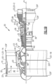
Figure 1A illustrates an example gas turbine engine. -
Figure 1B illustrates another example gas turbine engine. -
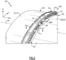
Figure 2 illustrates a perspective view of an assembly including components coupled along a flanged interface. -
Figure 3 illustrates a sectional view of the assembly taken along line 3-3 ofFigure 2 . -
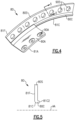
Figure 4 illustrates a perspective view of an example flange stiffener support. -
Figure 5 illustrates a sectional view of the flange stiffener support taken along line 5-5 ofFigure 4 . -
Figure 6 illustrates a sectional view of an example modular flange stiffener support. -
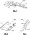
Figure 7 illustrates a perspective view of an example circumferential flange segment of the modular assembly ofFigure 6 . -
Figure 8 illustrates a perspective view of an example axial body segment of the modular assembly ofFigure 6 . -
Figure 9 illustrates a perspective view of an example flange fillet segment of the assembly ofFigure 6 . -
Figure 10 illustrates a pair of flange fillet/contoured segments attached to the circumferential flange segment. -
Figure 11 illustrates the flange fillet segment and the axial body segment attached to the circumferential flange segment. -
Figure 12A illustrates an end view of the circumferential flange segment and the flange fillet segment with another example protrusion and channel. -
Figure 12B illustrates an end view of the circumferential flange segment and the axial body segment with the example protrusion and channel ofFigure 12A . -
Figure 13A illustrates an end view of the circumferential flange segment and the flange fillet segment with yet another example protrusion and channel. -
Figure 13B illustrates an end view of the circumferential flange segment and the axial body segment with the example protrusion and channel ofFigure 13A . - Referring to
Figure 1A , agas turbine engine 10 includes afan section 11, acompressor section 12, acombustor section 13, and aturbine section 14. Air entering into thefan section 11 is initially compressed and fed to thecompressor section 12. In thecompressor section 12, the incoming air from thefan section 11 is further compressed and communicated to thecombustor section 13. In thecombustor section 13, the compressed air is mixed with gas and ignited to generate a hot exhaust stream E. The hot exhaust stream E is expanded through theturbine section 14 to drive thefan section 11 and thecompressor section 12. The exhaust gasses E flow from theturbine section 14 through anexhaust liner assembly 18. - The
engine 10 includes one ormore ducts 19 arranged about an engine central longitudinal axis A. Theducts 19 are dimensioned to bound a gas path of theengine 10, such as through the fan, compressor, andturbine sections exhaust liner assembly 18. In the illustrative example ofFigure 1A , theengine 10 includes a first duct 19-1 that bounds a portion of the gas path through thefan section 11. The duct 19-1 includes a pair of duct halves (indicated at 19-1A, 19-1B) that establish a "split" duct circumferentially distributed and arranged in an array about the longitudinal axis A to bound the gas path. -
Figure 1B schematically illustrates agas turbine engine 20. Thegas turbine engine 20 is disclosed herein as a two-spool turbofan that generally incorporates afan section 22, acompressor section 24, acombustor section 26 and a turbine section 28. Thefan section 22 drives air along a bypass flow path B in a bypass duct defined within a housing 15, such as a fan case or nacelle, and also drives air along a core flow path C for compression and communication into thecombustor section 26 then expansion through the turbine section 28. Although depicted as a two-spool turbofan gas turbine engine in the disclosed non-limiting embodiment, it should be understood that the concepts described herein are not limited to use with two-spool turbofans as the teachings may be applied to other types of turbine engines including three-spool architectures. - The
exemplary engine 20 generally includes alow speed spool 30 and ahigh speed spool 32 mounted for rotation about an engine central longitudinal axis A relative to an enginestatic structure 36 viaseveral bearing systems 38. It should be understood that various bearingsystems 38 at various locations may alternatively or additionally be provided, and the location of bearingsystems 38 may be varied as appropriate to the application. - The
low speed spool 30 generally includes aninner shaft 40 that interconnects, a first (or low)pressure compressor 44 and a first (or low)pressure turbine 46. Theinner shaft 40 is connected to thefan 42 through a speed change mechanism, which in exemplarygas turbine engine 20 is illustrated as a gearedarchitecture 48 to drive afan 42 at a lower speed than thelow speed spool 30. Thehigh speed spool 32 includes anouter shaft 50 that interconnects a second (or high)pressure compressor 52 and a second (or high)pressure turbine 54. Acombustor 56 is arranged inexemplary gas turbine 20 between thehigh pressure compressor 52 and thehigh pressure turbine 54. Amid-turbine frame 57 of the enginestatic structure 36 may be arranged generally between thehigh pressure turbine 54 and thelow pressure turbine 46. Themid-turbine frame 57 furthersupports bearing systems 38 in the turbine section 28. Theinner shaft 40 and theouter shaft 50 are concentric and rotate via bearingsystems 38 about the engine central longitudinal axis A which is collinear with their longitudinal axes. - The core airflow is compressed by the
low pressure compressor 44 then thehigh pressure compressor 52, mixed and burned with fuel in thecombustor 56, then expanded over thehigh pressure turbine 54 andlow pressure turbine 46. Themid-turbine frame 57 includesairfoils 59 which are in the core airflow path C. Theturbines low speed spool 30 andhigh speed spool 32 in response to the expansion. It will be appreciated that each of the positions of thefan section 22,compressor section 24,combustor section 26, turbine section 28, and fandrive gear system 48 may be varied. For example,gear system 48 may be located aft of the low pressure compressor, or aft of thecombustor section 26 or even aft of turbine section 28, andfan 42 may be positioned forward or aft of the location ofgear system 48. - The
engine 20 in one example is a high-bypass geared aircraft engine. In a further example, theengine 20 bypass ratio is greater than about six (6), with an example embodiment being greater than about ten (10), the gearedarchitecture 48 is an epicyclic gear train, such as a planetary gear system or other gear system, with a gear reduction ratio of greater than about 2.3 and thelow pressure turbine 46 has a pressure ratio that is greater than about five. In one disclosed embodiment, theengine 20 bypass ratio is greater than about ten (10:1), the fan diameter is significantly larger than that of thelow pressure compressor 44, and thelow pressure turbine 46 has a pressure ratio that is greater than about five 5:1.Low pressure turbine 46 pressure ratio is pressure measured prior to inlet oflow pressure turbine 46 as related to the pressure at the outlet of thelow pressure turbine 46 prior to an exhaust nozzle. The gearedarchitecture 48 may be an epicycle gear train, such as a planetary gear system or other gear system, with a gear reduction ratio of greater than about 2.3:1 and less than about 5:1. It should be understood, however, that the above parameters are only exemplary of one embodiment of a geared architecture engine and that the present disclosure is applicable to other gas turbine engines including direct drive turbofans. - A significant amount of thrust is provided by the bypass flow B due to the high bypass ratio. The
fan section 22 of theengine 20 is designed for a particular flight condition -- typically cruise at about 0.8 Mach and about 35,000 feet (10,668 meters). The flight condition of 0.8 Mach and 35,000 ft (10,668 meters), with the engine at its best fuel consumption - also known as "bucket cruise Thrust Specific Fuel Consumption ('TSFC')" - is the industry standard parameter of lbm of fuel being burned divided by lbf of thrust the engine produces at that minimum point. "Low fan pressure ratio" is the pressure ratio across the fan blade alone, without a Fan Exit Guide Vane ("FEGV") system. The low fan pressure ratio as disclosed herein according to one non-limiting embodiment is less than about 1.45. "Low corrected fan tip speed" is the actual fan tip speed in ft/sec divided by an industry standard temperature correction of [(Tram °R) / (518.7 °R)]0.5 (where °R = K x 9/5). The "Low corrected fan tip speed" as disclosed herein according to one non-limiting embodiment is less than about 1150 ft / second (350.5 meters/second). - The
engine 20 includes one ormore ducts 23 arranged about the engine central longitudinal axis A. Theducts 23 are dimensioned to bound a gas path of theengine 20, such as the bypass flow path B through thefan section 22 and the core flow path C through the compressor andturbine sections 24, 28. Eachduct 23 can include one ormore flanges 23F dimensioned to mount theduct 23 to another component, such as another one of theducts 23, or a nacelle or cowling. In the illustrative example ofFigure 1B , a first duct 23-1 establishes at least a portion of the housing 15. The first duct 23-1 bounds a flow path through thefan section 22, such as the bypass flow path B. The duct 23-1 includes a pair of duct halves (indicated at 23-1A, 23-1B) arranged about the longitudinal axis A. Another one of the ducts 23-2 can be incorporated in a turbine exhaust case (TEC) of the turbine section 28, for example. -
Figures 2-3 illustrate anexemplary assembly 60 for a gas turbine engine. Theassembly 60 can be incorporated into a portion of thegas turbine engines ducts - The
assembly 60 includes a first gasturbine engine component 62 and a second gasturbine engine component 64. In the illustrative example ofFigures 2-3 , theassembly 60 is a duct assembly, thefirst component 62 is a first duct, and thesecond component 64 is a second duct. Eachduct duct 19 ofFigure 1A . The first andsecond components flanged interface 66. Thefirst component 62 includes a first main (or duct)body 68 and afirst flange 70. Thesecond component 64 includes a second main (or duct)body 72 and asecond flange 74. - The
main bodies second components Figure 3 ). The longitudinal axis AA can be collinear with or parallel to with the engine longitudinal axis A of theengines second flanges circumference main bodies - The
assembly 60 includes at least oneinterface ring 76 trapped or positioned between theflanges interface ring 76 is dimensioned to extend at least partially or completely about the longitudinal axis AA. However, theinterface ring 76 is not required. In the illustrative example ofFigures 2-3 , theinterface ring 76 is astiffener ring 78 trapped or positioned between theflanges stiffener ring 78 can serve to provide increased rigidity and reduced deflection of theflanges flanged interface 66. Thestiffener ring 78 can also serve to provide support for radial stiffening members of shaft bearings. - The
assembly 60 includes at least oneflange stiffener support 80 outward of thefirst flange 70. Theflange stiffener support 80 is arranged such that thefirst flange 70 is trapped between theflange stiffener support 80 and theinterface ring 76. Theassembly 60 includes one or more fasteners F that fixedly attach theflanges interface ring 76. Example fasteners include bolts, screws, clips, pins and rivets. In the illustrative example ofFigures 2-3 , the fasteners F are bolts that mate with respective nuts. At least one fastener F extends through respective bores in the interface/stiffener ring 76/78 to fixedly attach theflanges Figure 3 . - Referring to
Figure 3 , with continuing reference toFigure 2 , themain bodies main bodies Figure 2 . Thefirst flange 70 is an "upturned" flange that extends outwardly in a radial (or third) direction R from the firstmain body 68 at a first junction (or elbow) 82. Thesecond flange 74 extends outwardly in the radial direction R from the secondmain body 72 at a second junction (or elbow) 84. Theflanges Figure 2 . It should be understood that thecomponents respective flanges flanges main bodies flanged interface 66. In other examples, theflanges main bodies - The first and
second junctions second junctions Figure 3 , thefirst junction 82 has a substantially arcuate geometry or profile with acorner filler 82A to create a substantially perpendicular profile at a radially inner side of the junction. Thecorner filler 82A includes ply layers that only extend in the region of thecorner filler 82A and not along a length of themain body 68. Thesecond junction 84 has a substantially perpendicular geometry or profile. For the purposes of this disclosure, the term "substantially" means ±10% of the disclosed relationship or value unless otherwise stated. - Various materials can be utilized to form each of the first and
second components stiffener ring 76/78 andflange stiffener support 80. The first and/orsecond components second flanges - In the illustrative example of
Figure 3 , thefirst component 62 is a composite duct made of a composite layup CL. The composite layup CL includes a plurality of ply layers PL in stacked relationship that follow acontour 83 of thefirst junction 82 to establish at least a portion of the firstmain body 68 and thefirst flange 70. Thecomponent 62 is radiused along thecontour 83 such that thejunction 82 has a substantially arcuate profile, as illustrated inFigure 3 . Thecontour 83 defines a concave (or inner) face 85 and a convex (or outer) face 87 on opposed sides of thejunction 82 that mates with thecorner filler 82A. The faces 85, 87 of thejunction 82 establish a substantially smooth transition between surfaces of themain body 68 and thefirst flange 70. In illustrative example ofFigure 3 , one of the ply layers PL extends along theconcave face 85 and another one of the ply layers PL extends along theconvex face 87, and the ply layers PL are arranged such that theflange 70 is substantially perpendicular to themain body 68. - The ply layers CL can be arranged to establish an
intermediate portion 86 interconnecting the firstmain body 68 and thefirst junction 82. The ply layers PL are arranged such that the ply layers PL slope radially inwardly from the firstmain body 68 in the radial direction R towards an adjacent portion of thefirst junction 82 with respect to the longitudinal axis AA, as illustrated inFigure 3 . The ply layers CL are arranged in the stacked relationship to establish a generally J-shaped cross-sectional geometry including thefirst junction 82. The arrangement of ply layers PL along theintermediate portion 86 establishes a depression DP extending in the circumferential direction T about thecircumference 69 of thefirst component 62. - Various materials can be utilized to form the composite layup CL including the ply layers PL. For examples, the composite layup CL can be constructed from continuous and/or discontinuous fibers arranged in various orientations and in one or more ply layers PL based on structural requirements. Example fiber materials include, but are not limited to, fiberglass, an aramid such as Kevlar®, a ceramic such as Nextel™, and a polyethylene such as Spectra®. The ply layers PL can be constructed from uni-tape plies having a plurality of fibers oriented in the same direction or can be constructed from a two-dimensional and/or three-dimensional network of fibers, which can be woven or interlaced. Other example fiber constructions include a network of stitched or non-crimped fabrics. The network of fibers can be formed from a dry fiber preform, or can be formed from a pre-impregnated ("prepreg") fabric or tape having fibers pre-impregnated with resin in a matrix, for example. In other examples, the fibers are infused with resin in a matrix subsequent to laying up the ply layers PL on a layup tool. In examples, the composite layup CL is made of an organic matric composites (OMC) or a ceramic matrix composites (CMC) including fibers in a matrix material. One or more coatings can be applied to surfaces of the composite layup CL.
- The
interface ring 76 can be dimensioned such that thefirst flange 70 sits on or is otherwise supported by theinterface ring 76 along an axial face of thefirst flange 70. In the illustrative example ofFigure 3 , theinterface ring 76 includes a flat mate face 77 having a constant axial dimension that mates with thefirst flange 70 and thecorner filler 82A. - As shown in
Figures 3-5 , theflange stiffener support 80 includes acircumferential flange segment 80S with aflange fillet segment 80C and anaxial body segment 80A both located adjacent a radially inner diameter of thecircumferential flange segment 80S. Thecircumferential flange segment 80S includes an axiallyupstream surface 81F that directly contacts thefirst flange 70 and a plurality of fastener openings 90S for accepting a fastener that extends through thefirst flange 70. - The
flange fillet segment 80C includes aflange fillet surface 81C that engages theconcave face 85 on themain body 68. Theflange fillet segment 80C also extends lengthwise in a circumferential direction to follow an outer contour of themain body 68 offirst duct 62. Theflange fillet surface 81C is dimensioned to substantially follow or complement theconcave face 85 of thecontour 83 such that theflange fillet surface 81C is opposed to the mate face 77 of theinterface ring 76 on the opposite side of thefirst flange 70. As shown inFigure 5 , theflange fillet segment 80C includes an axially aft most surface 81C2 that is axially downstream from an aft most surface offlange fillet segment 80C. One feature of this configuration is a greater contact area with thefirst duct 62 for load transfers. - The
axial body segment 80A includes a radially inward facingsurface 81A that is dimensioned to substantially follow or complement theconcave face 85 of thecontour 83. In the illustrated example, the radially inward facingsurface 81A is opposed to the mate face 77 of theinterface ring 76 on the opposite side of thefirst flange 70 in a first region and a flow path, such as the core flow path or the bypass flow path B, in a second region. Theaxial body segment 80A also includesfastener openings 90A adjacent a distal end for accepting a fastener F extending through themain body 68 of thefirst duct 62. In one example, thefastener openings 90A are located in a distal 50% of theaxial body segment 80A and in another example, the fastener openings are located in a distal 25% of theaxial body segment 80A. Additionally, in the illustrated example, an axial length of theaxial body segment 80A is greater than a radial height of thecircumferential flange segment 80S. Also, theaxial body segment 80A is circumferentially offset from theflange fillet segment 80C relative to the samecircumferential flange segment 80S. - One feature of locating the
fastener openings 90A adjacent the distal end of theaxial body segment 80A is that the fasteners F create a load path through thefirst flange 70, into theflange stiffener support 80, and through the fasteners F to themain body 68 of thefirst duct 62 to bypass defects in theduct 72 adjacent thefirst flange 70 as will be discussed in greater detail below. Additionally, a longitudinal axis of thefastener openings 90A is substantially perpendicular to a longitudinal axis of the fastener openings 90S. - Multiple flange stiffener supports 80 are arranged together to follow the
first flange 70 about a circumference of theduct 62 as shown inFigure 2 . At least one of the flange stiffener supports 80 includes theaxial body segment 80A with or without theflange fillet segment 80C. The inclusion of theflange fillet segment 80C with theaxial body segment 80A on a singleflange stiffener support 80 depends on the size and location of a defect D (SeeFigure 3 ) in the duct relative to theflange stiffener support 80. Also, an amount of radial variation in the axial direction can vary depending on a size of the depressed portion DP. In this disclosure, radial or radially, circumference or circumferentially, and axial or axially is relative to one of the axes A or AA unless stated otherwise. - As shown in the illustrated example of
Figure 4 , theaxial body segment 80A only extends along a portion of the circumferential width of theflange stiffener support 80. In one example, theaxial body segment 80A extends less than half the circumferential width of theflange stiffener support 80. In another example, theaxial body segment 80A extends at least 50% and up to 100% of the circumferential width of theflange stiffener support 80. Additionally, while the illustrated example shows theaxial body segment 80A located adjacent a circumferential end of thecircumferential flange segment 80S, theaxial body segment 80A could be located circumferentially inward from opposing circumferential ends of thecircumferential flange segment 80S. This would allow separateflange fillet segments 80C to separate theaxial body segment 80A from the opposing circumferential ends of theflange stiffener support 80. - One feature of the
flange stiffener support 80 is improved reinforcement of themain body 68 in the region of thefirst flange 70. In particular, it is possible for thefirst junction 82 and/or themain body 68 of thefirst duct 62 to include defects D in the ply layers PL from manufacturing that reduces the strength of thefirst duct 62 adjacent thefirst flange 70. If the defects D exceed predetermined criteria, such as size and location, theentire duct 62 might need to be discarded at a substantial financial loss and timing delay. Because theaxial body segment 80A extends axially past thefirst junction 82 and is fastened to themain body 68 with the fasteners F, a load path through thefirst flange 70 will bypass the defects D and extend to themain body 68. This can reduce the number ofducts 62 in the field that need to be replaced as thefirst junction 82 is also a region that experiences damage during use. - Also, as the region of the
first junction 82 is a possible region that can experience damage during operation, thisflange stiffener support 80 can also repairducts 62 that might otherwise be found unrepairable. In particular, as shown inFigure 3 , the defect D could extend entirely through themain body 68 of the first duct. The defect D could then be patched or filled with the area of the defect then strengthened by theaxial body segment 80A being circumferentially and axially aligned with an exterior of the defect D. -
Figures 6-11 illustrate anotherexample assembly 160 with aflange stiffener support 180 similar to theflange stiffener support 80 except where described below or shown in the Figures. Like or similar features between theflange stiffener support 80 and theflange stiffener support 180 will be identified with a leading "1." - In the illustrated examples, the
flange stiffener support 180 includes acircumferential flange segment 180S, at least oneaxial body segment 180A, and at least oneflange fillet segment 180C circumferentially offset from the at least oneaxial body segment 180A. Both theaxial body segment 180A and theflange fillet segment 180C circumferentially overlap with thecircumferential flange segment 180S. However, theaxial body segment 180A could extend an entire circumferential width of thecircumferential flange segment 180S without aflange fillet segment 180C. - As shown in
Figures 6-7 and10-11 , thecircumferential flange segment 180S includes achannel 192 that extends along a radially inner side of thecircumferential flange segment 180S. Thechannel 192 also extends circumferentially in a lengthwise direction to follow an outer contour of themain body 68 of thefirst duct 62. Thechannel 192 is configured to mate with a protrusion (or ridge) 194 on a radially outer edge of theflange fillet segment 180C or theaxial body segment 180A. The protrusion (or ridge) 194 also extends circumferentially in a lengthwise direction to follow an outer contour of themain body 68 of thefirst duct 62 and thechannel 192. Interfacing ledges are also located on oppose sides of thechannel 192 and protrusion (or ridge) 194 to prevent rotational movement of thecircumferential flange segment 180S relative to the axial andflange fillet segments - One feature of having the
channel 192 and protrusion (or ridge) 194 is to allow theaxial body segment 180A and theflange fillet segment 180C to engage by sliding in a circumferential direction relative to the circumferential flange segment with relative movement there between in the circumferential direction (SeeFigure 11 ). This also provides improved customization of the location of theaxial body segment 180A relative to themain body 68 of thefirst duct 62 without needed to manufacture a specific part that only provides a single configuration. For example, as shown inFigures 10-11 , multipleflange fillet segments 180C with different circumferential widths can mate with thecircumferential flange segment 180S. Similarly,axial body segments 180A with different circumferential widths could also mate with theflange fillet segment 180C. - While the protrusion (or ridge) 194 are located on the
axial body segment 180A and theflange fillet segment 180C to mate with thechannel 192 on thecircumferential flange segment 180S in the illustrated example, thechannel 192 could be located on theaxial body segment 180A and theflange fillet segment 180C with the protrusion (or ridge) 194 located on thecircumferential flange segment 180S. As the illustrated example shows, thechannel 192 and protrusion (or ridge)s 194 have complementary semicircular shapes, but other complementary shapes could be used for thechannel 192 and the protrusion (or ridge)s 194. In particular, as shown inFigures 12A and 12B , thecircumferential flange segment 180S could include achannel 192A and theflange fillet segment 180C and theaxial body segment 180A each include acomplementary protrusion 194A having a dovetail profile. Furthermore, as shown inFigures 13A and 13B , thecircumferential flange segment 180S could include achannel 192B and theflange fillet segment 180C and theaxial body segment 180A each include acomplementary protrusion 194B having a fir tree profile defined by a triangular profile having a number of protrusions on sides adjacent a distal tip of the triangular profile. - As shown in
Figures 7-11 , thechannel 192 and the protrusion (or ridge) 194 follow complementary arcuate profiles that allow either theflange fillet segment 180C or theaxial body segment 180A to slide into and out of engagement with thecircumferential flange segment 180S. One feature of the ability to select a position of the axially extending portion 180E and theflange fillet segment 180C is the ability to customize theflange stiffener support 180 to any specific damage or defects D in the plies P of theduct 62 without requiring a custom machined part or maintaining a large supply of replacement parts. Additionally, if only one of thecircumferential flange segment 180S,axial body segment 180A, orflange fillet segment 180C become damaged or worn, only the damaged or worn components needs to be replaced. - Although the different non-limiting examples are illustrated as having specific components, the examples of this disclosure are not limited to those particular combinations. It is possible to use some of the components or features from any of the non-limiting examples in combination with features or components from any of the other non-limiting examples.
- It should be understood that like reference numerals identify corresponding or similar elements throughout the several drawings. It should also be understood that although a particular component arrangement is disclosed and illustrated in these exemplary embodiments, other arrangements could also benefit from the teachings of this disclosure.
- The foregoing description shall be interpreted as illustrative and not in any limiting sense. A worker of ordinary skill in the art would understand that certain modifications could come within the scope of this disclosure. For these reasons, the following claim should be studied to determine the true scope and content of this disclosure.
Claims (15)
- A flange stiffener support for a duct in a gas turbine engine comprising:a circumferential flange segment (180S) having a plurality of flange fastener openings (90S); andan axial body segment (80A) extending from a radially inner side of the circumferential flange segment (180S) and having at least one body fastener opening (90A), wherein the axial body segment (80A) extends at least partially along a circumferential distance of the circumferential flange segment (180S).
- The flange stiffener support of claim 1, including a flange fillet segment (80C) extending from the radially inner side of the circumferential flange segment (180S) with an axial length less than an axial length of the axial body segment (80A), wherein the flange fillet segment (80C) is circumferentially spaced from the axial body segment (80A).
- The flange stiffener support of claim 2, wherein the axial length of the axial body segment (80A) is greater than a radial height of the circumferential flange segment (180S).
- The flange stiffener support of claim 2 or 3, wherein the circumferential flange segment (180S), the axial body segment (80A), and the flange fillet segment (80C) form a single unitary piece.
- The flange stiffener support of any of claims 2 to 4, wherein the flange fillet segment (80C) extends axially aft of an aft most surface on the circumferential flange segment (180S).
- The flange stiffener support of any of claims 2 to 5, wherein the circumferential flange segment (180S) includes one of a protrusion (194) or a channel (192) and the axial body segment (80A) and flange fillet segment (80C) each include the other of the protrusion (194) or the channel (192), optionally wherein each of the protrusion (194) and the channel (192) include a lengthwise direction that extends circumferentially with the circumferential flange segment (180S).
- The flange stiffener support of claim 6, wherein the protrusion (194) includes one of a dovetail profile or an arcuate profile.
- The flange stiffener support of claim 6, wherein the protrusion (194) includes a fir tree profile.
- The flange stiffener support of any of claims 2 to 8, wherein the axial body segment (80A) abuts a circumferential end of the flange fillet segment (80C), wherein a longitudinal axis of the at least one body fastener opening (90A) extends substantially perpendicular to a longitudinal axis the plurality of flange fastener openings (90S) in the circumferential flange segment (180S).
- The flange stiffener support of any of claims 2 to 9, wherein axial body segment (80A) extends a first circumferential distance and the flange fillet segment (80C) extends a second circumferential distance different from the first circumferential distance.
- A gas turbine engine comprising:a fan section (11);a compressor section (12);a turbine section (14) that drives the fan section (11) and the compressor section (12); anda duct assembly comprising:a first duct (62) including a main body (68) and a first flange (70), wherein the first duct (62) is made of a composite material;a second duct (64) including a main body (72) and a second flange (74); andthe flange stiffener support (80) of any preceding claim, wherein the flange stiffener support (80) engages the first flange (72).
- The gas turbine engine of claim 11, including an interface ring (76) abutting the first flange (70) and the second flange (74).
- A method of assembling a duct for a gas turbine engine, the method comprising:identifying a defect in a composite duct (62) adjacent a first flange (70); andselecting a flange stiffener support (80) for engaging the first flange (70), wherein the flange stiffener support (80) includes a circumferential flange segment (180S) having a plurality of fastener openings (90S) for securing to the first flange (70) and an axial body segment (80A) aligned with the defect and attached to a body portion of the composite duct (62).
- The method of claim 13, wherein selecting the flange stiffener support (80) includes slidably engaging the axial body segment (80A) with the circumferential flange segment (180S) of the flange stiffener support (80).
- The method of claim 13 or 14, wherein the circumferential flange segment (180S) includes one of a protrusion (194) or a channel (192) and the axial body segment (80A) include the other of the protrusion (194) or the channel (192).
Applications Claiming Priority (1)
| Application Number | Priority Date | Filing Date | Title |
|---|---|---|---|
| US17/958,946 US12084982B2 (en) | 2022-10-03 | 2022-10-03 | Flange and assembly for gas turbine engine case |
Publications (1)
| Publication Number | Publication Date |
|---|---|
| EP4350127A1 true EP4350127A1 (en) | 2024-04-10 |
Family
ID=88241235
Family Applications (1)
| Application Number | Title | Priority Date | Filing Date |
|---|---|---|---|
| EP23201454.8A Pending EP4350127A1 (en) | 2022-10-03 | 2023-10-03 | Flange and assembly for gas turbine engine case |
Country Status (2)
| Country | Link |
|---|---|
| US (1) | US12084982B2 (en) |
| EP (1) | EP4350127A1 (en) |
Citations (3)
| Publication number | Priority date | Publication date | Assignee | Title |
|---|---|---|---|---|
| US20080206044A1 (en) * | 2004-04-27 | 2008-08-28 | Airbus France | Noise reduction assembly for aircraft turbojet |
| US20100000227A1 (en) * | 2006-07-12 | 2010-01-07 | Airbus France | Air intake for an aircraft turbine engine |
| US20210003038A1 (en) * | 2019-07-02 | 2021-01-07 | United Technologies Corporation | Duct assembly for a gas turbine engine |
Family Cites Families (11)
| Publication number | Priority date | Publication date | Assignee | Title |
|---|---|---|---|---|
| US6305905B1 (en) * | 1999-05-05 | 2001-10-23 | United Technologies Corporation | Bolted-on propeller blade |
| US8079773B2 (en) * | 2005-10-18 | 2011-12-20 | General Electric Company | Methods and apparatus for assembling composite structures |
| US9140135B2 (en) | 2010-09-28 | 2015-09-22 | United Technologies Corporation | Metallic radius block for composite flange |
| WO2012147802A1 (en) * | 2011-04-26 | 2012-11-01 | 株式会社Ihi | Moulded article |
| FR2975970B1 (en) | 2011-05-30 | 2013-05-17 | Aircelle Sa | TOGETHER FOR AN AIRCRAFT NACELLE |
| FR2986582B1 (en) * | 2012-02-06 | 2014-03-14 | Snecma | BLOWER HOUSING FOR A GAS TURBINE ENGINE HAVING A FLANGE FOR ATTACHING EQUIPMENT |
| US10221718B2 (en) * | 2013-09-09 | 2019-03-05 | United Technologies Corporation | Fan cases and manufacture methods |
| US9879565B2 (en) * | 2015-01-20 | 2018-01-30 | United Technologies Corporation | Enclosed jacking insert |
| US10737986B2 (en) * | 2017-09-19 | 2020-08-11 | General Electric Company | Methods for repairing composite cylinders |
| US10968775B2 (en) * | 2017-11-28 | 2021-04-06 | General Electric Company | Support system having shape memory alloys |
| US11371390B2 (en) * | 2020-04-23 | 2022-06-28 | Raytheon Technologies Corporation | Assemblies for transferring compressive loads in flanges of composite gas turbine engine components |
-
2022
- 2022-10-03 US US17/958,946 patent/US12084982B2/en active Active
-
2023
- 2023-10-03 EP EP23201454.8A patent/EP4350127A1/en active Pending
Patent Citations (3)
| Publication number | Priority date | Publication date | Assignee | Title |
|---|---|---|---|---|
| US20080206044A1 (en) * | 2004-04-27 | 2008-08-28 | Airbus France | Noise reduction assembly for aircraft turbojet |
| US20100000227A1 (en) * | 2006-07-12 | 2010-01-07 | Airbus France | Air intake for an aircraft turbine engine |
| US20210003038A1 (en) * | 2019-07-02 | 2021-01-07 | United Technologies Corporation | Duct assembly for a gas turbine engine |
Also Published As
| Publication number | Publication date |
|---|---|
| US12084982B2 (en) | 2024-09-10 |
| US20240110492A1 (en) | 2024-04-04 |
Similar Documents
| Publication | Publication Date | Title |
|---|---|---|
| EP3819475B1 (en) | Blade outer air seal arrangement and method of sealing | |
| EP3892824B1 (en) | Pin attachment for cmc components in a gas turbine engine | |
| EP3734021B1 (en) | Blade outer air seal assembly | |
| EP3779131B1 (en) | Flow path component assembly and corresponding turbine section for a gas turbine engine | |
| US11105215B2 (en) | Feather seal slot arrangement for a CMC BOAS assembly | |
| EP3913197B1 (en) | Assemblies for transferring compressive loads in flanges of composite gas turbine engine components | |
| US12025020B2 (en) | Vane system with continuous support ring | |
| US11021987B2 (en) | CMC BOAS arrangement | |
| EP3719264B1 (en) | Turbine section comprising a cmc boas with transverse hook arrangement | |
| EP4579059A1 (en) | Blade configured for impact tolerance | |
| US10989059B2 (en) | CMC BOAS arrangement | |
| US11781432B2 (en) | Nested vane arrangement for gas turbine engine | |
| EP4350127A1 (en) | Flange and assembly for gas turbine engine case | |
| EP3712384A1 (en) | Blade outer air seal with seal carrier | |
| US20220275727A1 (en) | Platform for an airfoil of a gas turbine engine | |
| US11098608B2 (en) | CMC BOAS with internal support structure | |
| US11125099B2 (en) | Boas arrangement with double dovetail attachments |
Legal Events
| Date | Code | Title | Description |
|---|---|---|---|
| PUAI | Public reference made under article 153(3) epc to a published international application that has entered the european phase |
Free format text: ORIGINAL CODE: 0009012 |
|
| STAA | Information on the status of an ep patent application or granted ep patent |
Free format text: STATUS: THE APPLICATION HAS BEEN PUBLISHED |
|
| AK | Designated contracting states |
Kind code of ref document: A1 Designated state(s): AL AT BE BG CH CY CZ DE DK EE ES FI FR GB GR HR HU IE IS IT LI LT LU LV MC ME MK MT NL NO PL PT RO RS SE SI SK SM TR |
|
| STAA | Information on the status of an ep patent application or granted ep patent |
Free format text: STATUS: REQUEST FOR EXAMINATION WAS MADE |
|
| 17P | Request for examination filed |
Effective date: 20241009 |
|
| RBV | Designated contracting states (corrected) |
Designated state(s): AL AT BE BG CH CY CZ DE DK EE ES FI FR GB GR HR HU IE IS IT LI LT LU LV MC ME MK MT NL NO PL PT RO RS SE SI SK SM TR |
|
| GRAP | Despatch of communication of intention to grant a patent |
Free format text: ORIGINAL CODE: EPIDOSNIGR1 |
|
| STAA | Information on the status of an ep patent application or granted ep patent |
Free format text: STATUS: GRANT OF PATENT IS INTENDED |
|
| RIC1 | Information provided on ipc code assigned before grant |
Ipc: F01D 21/04 20060101AFI20251125BHEP Ipc: F01D 25/24 20060101ALI20251125BHEP Ipc: F01D 25/28 20060101ALI20251125BHEP |
|
| INTG | Intention to grant announced |
Effective date: 20251211 |
|
| GRAJ | Information related to disapproval of communication of intention to grant by the applicant or resumption of examination proceedings by the epo deleted |
Free format text: ORIGINAL CODE: EPIDOSDIGR1 |
|
| STAA | Information on the status of an ep patent application or granted ep patent |
Free format text: STATUS: REQUEST FOR EXAMINATION WAS MADE |
|
| GRAP | Despatch of communication of intention to grant a patent |
Free format text: ORIGINAL CODE: EPIDOSNIGR1 |
|
| STAA | Information on the status of an ep patent application or granted ep patent |
Free format text: STATUS: GRANT OF PATENT IS INTENDED |