EP4349799A1 - Barrier coating for gas turbine engine components - Google Patents
Barrier coating for gas turbine engine components Download PDFInfo
- Publication number
- EP4349799A1 EP4349799A1 EP23195094.0A EP23195094A EP4349799A1 EP 4349799 A1 EP4349799 A1 EP 4349799A1 EP 23195094 A EP23195094 A EP 23195094A EP 4349799 A1 EP4349799 A1 EP 4349799A1
- Authority
- EP
- European Patent Office
- Prior art keywords
- barrier coating
- phase
- substrate
- coat layer
- top coat
- Prior art date
- Legal status (The legal status is an assumption and is not a legal conclusion. Google has not performed a legal analysis and makes no representation as to the accuracy of the status listed.)
- Pending
Links
- 238000000576 coating method Methods 0.000 title claims abstract description 73
- 239000011248 coating agent Substances 0.000 title claims abstract description 68
- 230000004888 barrier function Effects 0.000 title claims abstract description 57
- 239000000463 material Substances 0.000 claims abstract description 56
- 239000000758 substrate Substances 0.000 claims abstract description 41
- 239000000919 ceramic Substances 0.000 claims abstract description 37
- 229910052761 rare earth metal Inorganic materials 0.000 claims abstract description 22
- QVGXLLKOCUKJST-UHFFFAOYSA-N atomic oxygen Chemical compound [O] QVGXLLKOCUKJST-UHFFFAOYSA-N 0.000 claims abstract description 15
- 239000001301 oxygen Substances 0.000 claims abstract description 15
- 229910052760 oxygen Inorganic materials 0.000 claims abstract description 15
- 150000001875 compounds Chemical class 0.000 claims abstract description 11
- 239000010955 niobium Substances 0.000 claims abstract description 11
- 229910052758 niobium Inorganic materials 0.000 claims abstract description 10
- GUCVJGMIXFAOAE-UHFFFAOYSA-N niobium atom Chemical compound [Nb] GUCVJGMIXFAOAE-UHFFFAOYSA-N 0.000 claims abstract description 10
- 229910052735 hafnium Inorganic materials 0.000 claims abstract description 7
- VBJZVLUMGGDVMO-UHFFFAOYSA-N hafnium atom Chemical compound [Hf] VBJZVLUMGGDVMO-UHFFFAOYSA-N 0.000 claims abstract description 7
- RTAQQCXQSZGOHL-UHFFFAOYSA-N Titanium Chemical compound [Ti] RTAQQCXQSZGOHL-UHFFFAOYSA-N 0.000 claims abstract description 6
- QCWXUUIWCKQGHC-UHFFFAOYSA-N Zirconium Chemical compound [Zr] QCWXUUIWCKQGHC-UHFFFAOYSA-N 0.000 claims abstract description 6
- 229910052715 tantalum Inorganic materials 0.000 claims abstract description 6
- GUVRBAGPIYLISA-UHFFFAOYSA-N tantalum atom Chemical compound [Ta] GUVRBAGPIYLISA-UHFFFAOYSA-N 0.000 claims abstract description 6
- 229910052719 titanium Inorganic materials 0.000 claims abstract description 6
- 239000010936 titanium Substances 0.000 claims abstract description 6
- 229910052726 zirconium Inorganic materials 0.000 claims abstract description 6
- 239000002131 composite material Substances 0.000 claims description 33
- 239000007789 gas Substances 0.000 claims description 29
- 229910052688 Gadolinium Inorganic materials 0.000 claims description 16
- 239000000956 alloy Substances 0.000 claims description 15
- 229910045601 alloy Inorganic materials 0.000 claims description 15
- UIWYJDYFSGRHKR-UHFFFAOYSA-N gadolinium atom Chemical compound [Gd] UIWYJDYFSGRHKR-UHFFFAOYSA-N 0.000 claims description 15
- 229910052746 lanthanum Inorganic materials 0.000 claims description 15
- 238000000034 method Methods 0.000 claims description 15
- FZLIPJUXYLNCLC-UHFFFAOYSA-N lanthanum atom Chemical compound [La] FZLIPJUXYLNCLC-UHFFFAOYSA-N 0.000 claims description 14
- 229910000601 superalloy Inorganic materials 0.000 claims description 14
- 238000007750 plasma spraying Methods 0.000 claims description 9
- 229910052782 aluminium Inorganic materials 0.000 claims description 6
- 239000004411 aluminium Substances 0.000 claims description 6
- XAGFODPZIPBFFR-UHFFFAOYSA-N aluminium Chemical compound [Al] XAGFODPZIPBFFR-UHFFFAOYSA-N 0.000 claims description 6
- 238000005328 electron beam physical vapour deposition Methods 0.000 claims description 6
- 239000012720 thermal barrier coating Substances 0.000 claims description 6
- XUIMIQQOPSSXEZ-UHFFFAOYSA-N Silicon Chemical compound [Si] XUIMIQQOPSSXEZ-UHFFFAOYSA-N 0.000 claims description 5
- 238000004519 manufacturing process Methods 0.000 claims description 5
- 229910052710 silicon Inorganic materials 0.000 claims description 5
- 239000010703 silicon Substances 0.000 claims description 5
- 239000000725 suspension Substances 0.000 claims description 5
- 229910052727 yttrium Inorganic materials 0.000 claims description 5
- VWQVUPCCIRVNHF-UHFFFAOYSA-N yttrium atom Chemical compound [Y] VWQVUPCCIRVNHF-UHFFFAOYSA-N 0.000 claims description 5
- VYZAMTAEIAYCRO-UHFFFAOYSA-N Chromium Chemical compound [Cr] VYZAMTAEIAYCRO-UHFFFAOYSA-N 0.000 claims description 4
- 229910000831 Steel Inorganic materials 0.000 claims description 4
- 239000011153 ceramic matrix composite Substances 0.000 claims description 4
- 229910052804 chromium Inorganic materials 0.000 claims description 4
- 239000011651 chromium Substances 0.000 claims description 4
- 230000007613 environmental effect Effects 0.000 claims description 4
- 239000000446 fuel Substances 0.000 claims description 4
- 229910000765 intermetallic Inorganic materials 0.000 claims description 4
- 239000003870 refractory metal Substances 0.000 claims description 4
- 239000010959 steel Substances 0.000 claims description 4
- 239000002243 precursor Substances 0.000 claims description 3
- 150000004760 silicates Chemical class 0.000 claims description 3
- MCMNRKCIXSYSNV-UHFFFAOYSA-N Zirconium dioxide Chemical compound O=[Zr]=O MCMNRKCIXSYSNV-UHFFFAOYSA-N 0.000 description 10
- 229910052586 apatite Inorganic materials 0.000 description 10
- 150000002910 rare earth metals Chemical class 0.000 description 10
- 238000001000 micrograph Methods 0.000 description 8
- PXHVJJICTQNCMI-UHFFFAOYSA-N Nickel Chemical compound [Ni] PXHVJJICTQNCMI-UHFFFAOYSA-N 0.000 description 7
- XEEYBQQBJWHFJM-UHFFFAOYSA-N Iron Chemical compound [Fe] XEEYBQQBJWHFJM-UHFFFAOYSA-N 0.000 description 6
- 229910000323 aluminium silicate Inorganic materials 0.000 description 6
- 230000007246 mechanism Effects 0.000 description 6
- 230000003647 oxidation Effects 0.000 description 6
- 238000007254 oxidation reaction Methods 0.000 description 6
- 239000000843 powder Substances 0.000 description 6
- 239000000203 mixture Substances 0.000 description 5
- BASFCYQUMIYNBI-UHFFFAOYSA-N platinum Chemical compound [Pt] BASFCYQUMIYNBI-UHFFFAOYSA-N 0.000 description 5
- 229910052596 spinel Inorganic materials 0.000 description 5
- 229910002338 LaNbO4 Inorganic materials 0.000 description 4
- VYPSYNLAJGMNEJ-UHFFFAOYSA-N Silicium dioxide Chemical compound O=[Si]=O VYPSYNLAJGMNEJ-UHFFFAOYSA-N 0.000 description 4
- 238000002441 X-ray diffraction Methods 0.000 description 4
- CETPSERCERDGAM-UHFFFAOYSA-N ceric oxide Chemical compound O=[Ce]=O CETPSERCERDGAM-UHFFFAOYSA-N 0.000 description 4
- 238000005260 corrosion Methods 0.000 description 4
- 230000007797 corrosion Effects 0.000 description 4
- 238000007373 indentation Methods 0.000 description 4
- 239000011029 spinel Substances 0.000 description 4
- 239000000126 substance Substances 0.000 description 4
- PNEYBMLMFCGWSK-UHFFFAOYSA-N aluminium oxide Inorganic materials [O-2].[O-2].[O-2].[Al+3].[Al+3] PNEYBMLMFCGWSK-UHFFFAOYSA-N 0.000 description 3
- 238000006243 chemical reaction Methods 0.000 description 3
- 238000002485 combustion reaction Methods 0.000 description 3
- 230000008595 infiltration Effects 0.000 description 3
- 238000001764 infiltration Methods 0.000 description 3
- 229910052742 iron Inorganic materials 0.000 description 3
- 229910052759 nickel Inorganic materials 0.000 description 3
- 230000035515 penetration Effects 0.000 description 3
- 239000002244 precipitate Substances 0.000 description 3
- 229910010271 silicon carbide Inorganic materials 0.000 description 3
- -1 ytterbium silicates Chemical class 0.000 description 3
- 229910001233 yttria-stabilized zirconia Inorganic materials 0.000 description 3
- LFQSCWFLJHTTHZ-UHFFFAOYSA-N Ethanol Chemical compound CCO LFQSCWFLJHTTHZ-UHFFFAOYSA-N 0.000 description 2
- KDLHZDBZIXYQEI-UHFFFAOYSA-N Palladium Chemical compound [Pd] KDLHZDBZIXYQEI-UHFFFAOYSA-N 0.000 description 2
- GWEVSGVZZGPLCZ-UHFFFAOYSA-N Titan oxide Chemical compound O=[Ti]=O GWEVSGVZZGPLCZ-UHFFFAOYSA-N 0.000 description 2
- 229910052769 Ytterbium Inorganic materials 0.000 description 2
- 230000015556 catabolic process Effects 0.000 description 2
- 229910010293 ceramic material Inorganic materials 0.000 description 2
- 229910000422 cerium(IV) oxide Inorganic materials 0.000 description 2
- 229910017052 cobalt Inorganic materials 0.000 description 2
- 239000010941 cobalt Substances 0.000 description 2
- GUTLYIVDDKVIGB-UHFFFAOYSA-N cobalt atom Chemical compound [Co] GUTLYIVDDKVIGB-UHFFFAOYSA-N 0.000 description 2
- 238000006731 degradation reaction Methods 0.000 description 2
- CMIHHWBVHJVIGI-UHFFFAOYSA-N gadolinium(iii) oxide Chemical compound [O-2].[O-2].[O-2].[Gd+3].[Gd+3] CMIHHWBVHJVIGI-UHFFFAOYSA-N 0.000 description 2
- 239000000395 magnesium oxide Substances 0.000 description 2
- CPLXHLVBOLITMK-UHFFFAOYSA-N magnesium oxide Inorganic materials [Mg]=O CPLXHLVBOLITMK-UHFFFAOYSA-N 0.000 description 2
- AXZKOIWUVFPNLO-UHFFFAOYSA-N magnesium;oxygen(2-) Chemical compound [O-2].[Mg+2] AXZKOIWUVFPNLO-UHFFFAOYSA-N 0.000 description 2
- 229910000484 niobium oxide Inorganic materials 0.000 description 2
- ZKATWMILCYLAPD-UHFFFAOYSA-N niobium pentoxide Chemical compound O=[Nb](=O)O[Nb](=O)=O ZKATWMILCYLAPD-UHFFFAOYSA-N 0.000 description 2
- URLJKFSTXLNXLG-UHFFFAOYSA-N niobium(5+);oxygen(2-) Chemical compound [O-2].[O-2].[O-2].[O-2].[O-2].[Nb+5].[Nb+5] URLJKFSTXLNXLG-UHFFFAOYSA-N 0.000 description 2
- 230000000737 periodic effect Effects 0.000 description 2
- 229910052697 platinum Inorganic materials 0.000 description 2
- 230000001141 propulsive effect Effects 0.000 description 2
- HYXGAEYDKFCVMU-UHFFFAOYSA-N scandium oxide Chemical compound O=[Sc]O[Sc]=O HYXGAEYDKFCVMU-UHFFFAOYSA-N 0.000 description 2
- HBMJWWWQQXIZIP-UHFFFAOYSA-N silicon carbide Chemical compound [Si+]#[C-] HBMJWWWQQXIZIP-UHFFFAOYSA-N 0.000 description 2
- 239000000377 silicon dioxide Substances 0.000 description 2
- 238000005050 thermomechanical fatigue Methods 0.000 description 2
- ODINCKMPIJJUCX-UHFFFAOYSA-N Calcium oxide Chemical compound [Ca]=O ODINCKMPIJJUCX-UHFFFAOYSA-N 0.000 description 1
- 229910052684 Cerium Inorganic materials 0.000 description 1
- 229910052692 Dysprosium Inorganic materials 0.000 description 1
- 229910052691 Erbium Inorganic materials 0.000 description 1
- 229910052693 Europium Inorganic materials 0.000 description 1
- MBMLMWLHJBBADN-UHFFFAOYSA-N Ferrous sulfide Chemical compound [Fe]=S MBMLMWLHJBBADN-UHFFFAOYSA-N 0.000 description 1
- 229910052689 Holmium Inorganic materials 0.000 description 1
- UFHFLCQGNIYNRP-UHFFFAOYSA-N Hydrogen Chemical compound [H][H] UFHFLCQGNIYNRP-UHFFFAOYSA-N 0.000 description 1
- 229910052765 Lutetium Inorganic materials 0.000 description 1
- 229910026161 MgAl2O4 Inorganic materials 0.000 description 1
- ZOKXTWBITQBERF-UHFFFAOYSA-N Molybdenum Chemical compound [Mo] ZOKXTWBITQBERF-UHFFFAOYSA-N 0.000 description 1
- 229910052779 Neodymium Inorganic materials 0.000 description 1
- 229910052777 Praseodymium Inorganic materials 0.000 description 1
- NPXOKRUENSOPAO-UHFFFAOYSA-N Raney nickel Chemical compound [Al].[Ni] NPXOKRUENSOPAO-UHFFFAOYSA-N 0.000 description 1
- 229910052772 Samarium Inorganic materials 0.000 description 1
- 229910052771 Terbium Inorganic materials 0.000 description 1
- 229910052775 Thulium Inorganic materials 0.000 description 1
- HTRAGCPMBJXKRI-UHFFFAOYSA-N [Gd].[Ca] Chemical compound [Gd].[Ca] HTRAGCPMBJXKRI-UHFFFAOYSA-N 0.000 description 1
- XEDZPTDJMMNSIB-UHFFFAOYSA-N [Si]([O-])([O-])([O-])O.[Y+3] Chemical compound [Si]([O-])([O-])([O-])O.[Y+3] XEDZPTDJMMNSIB-UHFFFAOYSA-N 0.000 description 1
- 230000001464 adherent effect Effects 0.000 description 1
- 238000000498 ball milling Methods 0.000 description 1
- 230000015572 biosynthetic process Effects 0.000 description 1
- 239000011575 calcium Substances 0.000 description 1
- 239000000378 calcium silicate Substances 0.000 description 1
- 229910052918 calcium silicate Inorganic materials 0.000 description 1
- 150000004649 carbonic acid derivatives Chemical class 0.000 description 1
- 229910052729 chemical element Inorganic materials 0.000 description 1
- 230000006835 compression Effects 0.000 description 1
- 238000007906 compression Methods 0.000 description 1
- 238000001816 cooling Methods 0.000 description 1
- RKTYLMNFRDHKIL-UHFFFAOYSA-N copper;5,10,15,20-tetraphenylporphyrin-22,24-diide Chemical compound [Cu+2].C1=CC(C(=C2C=CC([N-]2)=C(C=2C=CC=CC=2)C=2C=CC(N=2)=C(C=2C=CC=CC=2)C2=CC=C3[N-]2)C=2C=CC=CC=2)=NC1=C3C1=CC=CC=C1 RKTYLMNFRDHKIL-UHFFFAOYSA-N 0.000 description 1
- 239000013078 crystal Substances 0.000 description 1
- 230000032798 delamination Effects 0.000 description 1
- 230000001419 dependent effect Effects 0.000 description 1
- 238000000151 deposition Methods 0.000 description 1
- QDOXWKRWXJOMAK-UHFFFAOYSA-N dichromium trioxide Chemical compound O=[Cr]O[Cr]=O QDOXWKRWXJOMAK-UHFFFAOYSA-N 0.000 description 1
- 238000009792 diffusion process Methods 0.000 description 1
- KZHJGOXRZJKJNY-UHFFFAOYSA-N dioxosilane;oxo(oxoalumanyloxy)alumane Chemical compound O=[Si]=O.O=[Si]=O.O=[Al]O[Al]=O.O=[Al]O[Al]=O.O=[Al]O[Al]=O KZHJGOXRZJKJNY-UHFFFAOYSA-N 0.000 description 1
- 239000011363 dried mixture Substances 0.000 description 1
- 229910001938 gadolinium oxide Inorganic materials 0.000 description 1
- 229940075613 gadolinium oxide Drugs 0.000 description 1
- PCHJSUWPFVWCPO-UHFFFAOYSA-N gold Chemical compound [Au] PCHJSUWPFVWCPO-UHFFFAOYSA-N 0.000 description 1
- 229910052737 gold Inorganic materials 0.000 description 1
- 239000010931 gold Substances 0.000 description 1
- 229910000449 hafnium oxide Inorganic materials 0.000 description 1
- WIHZLLGSGQNAGK-UHFFFAOYSA-N hafnium(4+);oxygen(2-) Chemical compound [O-2].[O-2].[Hf+4] WIHZLLGSGQNAGK-UHFFFAOYSA-N 0.000 description 1
- 238000010438 heat treatment Methods 0.000 description 1
- 239000001307 helium Substances 0.000 description 1
- 229910052734 helium Inorganic materials 0.000 description 1
- SWQJXJOGLNCZEY-UHFFFAOYSA-N helium atom Chemical compound [He] SWQJXJOGLNCZEY-UHFFFAOYSA-N 0.000 description 1
- 239000001257 hydrogen Substances 0.000 description 1
- 229910052739 hydrogen Inorganic materials 0.000 description 1
- 150000004679 hydroxides Chemical class 0.000 description 1
- 229910001026 inconel Inorganic materials 0.000 description 1
- 229910052909 inorganic silicate Inorganic materials 0.000 description 1
- 229910052747 lanthanoid Inorganic materials 0.000 description 1
- 150000002602 lanthanoids Chemical class 0.000 description 1
- RIAXXCZORHQTQD-UHFFFAOYSA-N lanthanum magnesium Chemical compound [Mg].[La] RIAXXCZORHQTQD-UHFFFAOYSA-N 0.000 description 1
- MRELNEQAGSRDBK-UHFFFAOYSA-N lanthanum oxide Inorganic materials [O-2].[O-2].[O-2].[La+3].[La+3] MRELNEQAGSRDBK-UHFFFAOYSA-N 0.000 description 1
- 229910052749 magnesium Inorganic materials 0.000 description 1
- 239000011777 magnesium Substances 0.000 description 1
- 239000011159 matrix material Substances 0.000 description 1
- 239000000155 melt Substances 0.000 description 1
- 238000002844 melting Methods 0.000 description 1
- 230000008018 melting Effects 0.000 description 1
- 229910052751 metal Inorganic materials 0.000 description 1
- 239000002184 metal Substances 0.000 description 1
- 229910052750 molybdenum Inorganic materials 0.000 description 1
- 239000011733 molybdenum Substances 0.000 description 1
- 229910052863 mullite Inorganic materials 0.000 description 1
- 229910000907 nickel aluminide Inorganic materials 0.000 description 1
- TWNQGVIAIRXVLR-UHFFFAOYSA-N oxo(oxoalumanyloxy)alumane Chemical compound O=[Al]O[Al]=O TWNQGVIAIRXVLR-UHFFFAOYSA-N 0.000 description 1
- KTUFCUMIWABKDW-UHFFFAOYSA-N oxo(oxolanthaniooxy)lanthanum Chemical compound O=[La]O[La]=O KTUFCUMIWABKDW-UHFFFAOYSA-N 0.000 description 1
- SIWVEOZUMHYXCS-UHFFFAOYSA-N oxo(oxoyttriooxy)yttrium Chemical compound O=[Y]O[Y]=O SIWVEOZUMHYXCS-UHFFFAOYSA-N 0.000 description 1
- BPUBBGLMJRNUCC-UHFFFAOYSA-N oxygen(2-);tantalum(5+) Chemical compound [O-2].[O-2].[O-2].[O-2].[O-2].[Ta+5].[Ta+5] BPUBBGLMJRNUCC-UHFFFAOYSA-N 0.000 description 1
- RVTZCBVAJQQJTK-UHFFFAOYSA-N oxygen(2-);zirconium(4+) Chemical compound [O-2].[O-2].[Zr+4] RVTZCBVAJQQJTK-UHFFFAOYSA-N 0.000 description 1
- 229910052763 palladium Inorganic materials 0.000 description 1
- VSIIXMUUUJUKCM-UHFFFAOYSA-D pentacalcium;fluoride;triphosphate Chemical compound [F-].[Ca+2].[Ca+2].[Ca+2].[Ca+2].[Ca+2].[O-]P([O-])([O-])=O.[O-]P([O-])([O-])=O.[O-]P([O-])([O-])=O VSIIXMUUUJUKCM-UHFFFAOYSA-D 0.000 description 1
- 238000002360 preparation method Methods 0.000 description 1
- 238000001272 pressureless sintering Methods 0.000 description 1
- 239000000047 product Substances 0.000 description 1
- 239000011253 protective coating Substances 0.000 description 1
- 229910001404 rare earth metal oxide Inorganic materials 0.000 description 1
- VSZWPYCFIRKVQL-UHFFFAOYSA-N selanylidenegallium;selenium Chemical compound [Se].[Se]=[Ga].[Se]=[Ga] VSZWPYCFIRKVQL-UHFFFAOYSA-N 0.000 description 1
- 238000007873 sieving Methods 0.000 description 1
- 238000003746 solid phase reaction Methods 0.000 description 1
- 238000010671 solid-state reaction Methods 0.000 description 1
- 238000002490 spark plasma sintering Methods 0.000 description 1
- 239000003381 stabilizer Substances 0.000 description 1
- FCCTVDGKMTZSPU-UHFFFAOYSA-N strontium;dioxido(oxo)zirconium Chemical compound [Sr+2].[O-][Zr]([O-])=O FCCTVDGKMTZSPU-UHFFFAOYSA-N 0.000 description 1
- VRRFSFYSLSPWQY-UHFFFAOYSA-N sulfanylidenecobalt Chemical compound [Co]=S VRRFSFYSLSPWQY-UHFFFAOYSA-N 0.000 description 1
- WWNBZGLDODTKEM-UHFFFAOYSA-N sulfanylidenenickel Chemical compound [Ni]=S WWNBZGLDODTKEM-UHFFFAOYSA-N 0.000 description 1
- 229910001936 tantalum oxide Inorganic materials 0.000 description 1
- OGIDPMRJRNCKJF-UHFFFAOYSA-N titanium oxide Inorganic materials [Ti]=O OGIDPMRJRNCKJF-UHFFFAOYSA-N 0.000 description 1
- AKTQKAXQEMMCIF-UHFFFAOYSA-N trioxido(trioxidosilyloxy)silane;yttrium(3+) Chemical compound [Y+3].[Y+3].[O-][Si]([O-])([O-])O[Si]([O-])([O-])[O-] AKTQKAXQEMMCIF-UHFFFAOYSA-N 0.000 description 1
- RUDFQVOCFDJEEF-UHFFFAOYSA-N yttrium(III) oxide Inorganic materials [O-2].[O-2].[O-2].[Y+3].[Y+3] RUDFQVOCFDJEEF-UHFFFAOYSA-N 0.000 description 1
- 229910001928 zirconium oxide Inorganic materials 0.000 description 1
Images




Classifications
-
- C—CHEMISTRY; METALLURGY
- C04—CEMENTS; CONCRETE; ARTIFICIAL STONE; CERAMICS; REFRACTORIES
- C04B—LIME, MAGNESIA; SLAG; CEMENTS; COMPOSITIONS THEREOF, e.g. MORTARS, CONCRETE OR LIKE BUILDING MATERIALS; ARTIFICIAL STONE; CERAMICS; REFRACTORIES; TREATMENT OF NATURAL STONE
- C04B41/00—After-treatment of mortars, concrete, artificial stone or ceramics; Treatment of natural stone
- C04B41/45—Coating or impregnating, e.g. injection in masonry, partial coating of green or fired ceramics, organic coating compositions for adhering together two concrete elements
- C04B41/52—Multiple coating or impregnating multiple coating or impregnating with the same composition or with compositions only differing in the concentration of the constituents, is classified as single coating or impregnation
-
- C—CHEMISTRY; METALLURGY
- C04—CEMENTS; CONCRETE; ARTIFICIAL STONE; CERAMICS; REFRACTORIES
- C04B—LIME, MAGNESIA; SLAG; CEMENTS; COMPOSITIONS THEREOF, e.g. MORTARS, CONCRETE OR LIKE BUILDING MATERIALS; ARTIFICIAL STONE; CERAMICS; REFRACTORIES; TREATMENT OF NATURAL STONE
- C04B35/00—Shaped ceramic products characterised by their composition; Ceramics compositions; Processing powders of inorganic compounds preparatory to the manufacturing of ceramic products
- C04B35/01—Shaped ceramic products characterised by their composition; Ceramics compositions; Processing powders of inorganic compounds preparatory to the manufacturing of ceramic products based on oxide ceramics
- C04B35/46—Shaped ceramic products characterised by their composition; Ceramics compositions; Processing powders of inorganic compounds preparatory to the manufacturing of ceramic products based on oxide ceramics based on titanium oxides or titanates
- C04B35/462—Shaped ceramic products characterised by their composition; Ceramics compositions; Processing powders of inorganic compounds preparatory to the manufacturing of ceramic products based on oxide ceramics based on titanium oxides or titanates based on titanates
-
- C—CHEMISTRY; METALLURGY
- C04—CEMENTS; CONCRETE; ARTIFICIAL STONE; CERAMICS; REFRACTORIES
- C04B—LIME, MAGNESIA; SLAG; CEMENTS; COMPOSITIONS THEREOF, e.g. MORTARS, CONCRETE OR LIKE BUILDING MATERIALS; ARTIFICIAL STONE; CERAMICS; REFRACTORIES; TREATMENT OF NATURAL STONE
- C04B35/00—Shaped ceramic products characterised by their composition; Ceramics compositions; Processing powders of inorganic compounds preparatory to the manufacturing of ceramic products
- C04B35/01—Shaped ceramic products characterised by their composition; Ceramics compositions; Processing powders of inorganic compounds preparatory to the manufacturing of ceramic products based on oxide ceramics
- C04B35/48—Shaped ceramic products characterised by their composition; Ceramics compositions; Processing powders of inorganic compounds preparatory to the manufacturing of ceramic products based on oxide ceramics based on zirconium or hafnium oxides, zirconates, zircon or hafnates
- C04B35/486—Fine ceramics
- C04B35/488—Composites
-
- C—CHEMISTRY; METALLURGY
- C04—CEMENTS; CONCRETE; ARTIFICIAL STONE; CERAMICS; REFRACTORIES
- C04B—LIME, MAGNESIA; SLAG; CEMENTS; COMPOSITIONS THEREOF, e.g. MORTARS, CONCRETE OR LIKE BUILDING MATERIALS; ARTIFICIAL STONE; CERAMICS; REFRACTORIES; TREATMENT OF NATURAL STONE
- C04B41/00—After-treatment of mortars, concrete, artificial stone or ceramics; Treatment of natural stone
- C04B41/45—Coating or impregnating, e.g. injection in masonry, partial coating of green or fired ceramics, organic coating compositions for adhering together two concrete elements
- C04B41/4505—Coating or impregnating, e.g. injection in masonry, partial coating of green or fired ceramics, organic coating compositions for adhering together two concrete elements characterised by the method of application
- C04B41/4523—Coating or impregnating, e.g. injection in masonry, partial coating of green or fired ceramics, organic coating compositions for adhering together two concrete elements characterised by the method of application applied from the molten state ; Thermal spraying, e.g. plasma spraying
-
- C—CHEMISTRY; METALLURGY
- C04—CEMENTS; CONCRETE; ARTIFICIAL STONE; CERAMICS; REFRACTORIES
- C04B—LIME, MAGNESIA; SLAG; CEMENTS; COMPOSITIONS THEREOF, e.g. MORTARS, CONCRETE OR LIKE BUILDING MATERIALS; ARTIFICIAL STONE; CERAMICS; REFRACTORIES; TREATMENT OF NATURAL STONE
- C04B41/00—After-treatment of mortars, concrete, artificial stone or ceramics; Treatment of natural stone
- C04B41/45—Coating or impregnating, e.g. injection in masonry, partial coating of green or fired ceramics, organic coating compositions for adhering together two concrete elements
- C04B41/52—Multiple coating or impregnating multiple coating or impregnating with the same composition or with compositions only differing in the concentration of the constituents, is classified as single coating or impregnation
- C04B41/522—Multiple coatings, for one of the coatings of which at least one alternative is described
-
- C—CHEMISTRY; METALLURGY
- C04—CEMENTS; CONCRETE; ARTIFICIAL STONE; CERAMICS; REFRACTORIES
- C04B—LIME, MAGNESIA; SLAG; CEMENTS; COMPOSITIONS THEREOF, e.g. MORTARS, CONCRETE OR LIKE BUILDING MATERIALS; ARTIFICIAL STONE; CERAMICS; REFRACTORIES; TREATMENT OF NATURAL STONE
- C04B41/00—After-treatment of mortars, concrete, artificial stone or ceramics; Treatment of natural stone
- C04B41/80—After-treatment of mortars, concrete, artificial stone or ceramics; Treatment of natural stone of only ceramics
- C04B41/81—Coating or impregnation
- C04B41/85—Coating or impregnation with inorganic materials
- C04B41/87—Ceramics
-
- C—CHEMISTRY; METALLURGY
- C23—COATING METALLIC MATERIAL; COATING MATERIAL WITH METALLIC MATERIAL; CHEMICAL SURFACE TREATMENT; DIFFUSION TREATMENT OF METALLIC MATERIAL; COATING BY VACUUM EVAPORATION, BY SPUTTERING, BY ION IMPLANTATION OR BY CHEMICAL VAPOUR DEPOSITION, IN GENERAL; INHIBITING CORROSION OF METALLIC MATERIAL OR INCRUSTATION IN GENERAL
- C23C—COATING METALLIC MATERIAL; COATING MATERIAL WITH METALLIC MATERIAL; SURFACE TREATMENT OF METALLIC MATERIAL BY DIFFUSION INTO THE SURFACE, BY CHEMICAL CONVERSION OR SUBSTITUTION; COATING BY VACUUM EVAPORATION, BY SPUTTERING, BY ION IMPLANTATION OR BY CHEMICAL VAPOUR DEPOSITION, IN GENERAL
- C23C28/00—Coating for obtaining at least two superposed coatings either by methods not provided for in a single one of groups C23C2/00 - C23C26/00 or by combinations of methods provided for in subclasses C23C and C25C or C25D
- C23C28/30—Coatings combining at least one metallic layer and at least one inorganic non-metallic layer
- C23C28/32—Coatings combining at least one metallic layer and at least one inorganic non-metallic layer including at least one pure metallic layer
-
- C—CHEMISTRY; METALLURGY
- C23—COATING METALLIC MATERIAL; COATING MATERIAL WITH METALLIC MATERIAL; CHEMICAL SURFACE TREATMENT; DIFFUSION TREATMENT OF METALLIC MATERIAL; COATING BY VACUUM EVAPORATION, BY SPUTTERING, BY ION IMPLANTATION OR BY CHEMICAL VAPOUR DEPOSITION, IN GENERAL; INHIBITING CORROSION OF METALLIC MATERIAL OR INCRUSTATION IN GENERAL
- C23C—COATING METALLIC MATERIAL; COATING MATERIAL WITH METALLIC MATERIAL; SURFACE TREATMENT OF METALLIC MATERIAL BY DIFFUSION INTO THE SURFACE, BY CHEMICAL CONVERSION OR SUBSTITUTION; COATING BY VACUUM EVAPORATION, BY SPUTTERING, BY ION IMPLANTATION OR BY CHEMICAL VAPOUR DEPOSITION, IN GENERAL
- C23C28/00—Coating for obtaining at least two superposed coatings either by methods not provided for in a single one of groups C23C2/00 - C23C26/00 or by combinations of methods provided for in subclasses C23C and C25C or C25D
- C23C28/30—Coatings combining at least one metallic layer and at least one inorganic non-metallic layer
- C23C28/32—Coatings combining at least one metallic layer and at least one inorganic non-metallic layer including at least one pure metallic layer
- C23C28/321—Coatings combining at least one metallic layer and at least one inorganic non-metallic layer including at least one pure metallic layer with at least one metal alloy layer
- C23C28/3215—Coatings combining at least one metallic layer and at least one inorganic non-metallic layer including at least one pure metallic layer with at least one metal alloy layer at least one MCrAlX layer
-
- C—CHEMISTRY; METALLURGY
- C23—COATING METALLIC MATERIAL; COATING MATERIAL WITH METALLIC MATERIAL; CHEMICAL SURFACE TREATMENT; DIFFUSION TREATMENT OF METALLIC MATERIAL; COATING BY VACUUM EVAPORATION, BY SPUTTERING, BY ION IMPLANTATION OR BY CHEMICAL VAPOUR DEPOSITION, IN GENERAL; INHIBITING CORROSION OF METALLIC MATERIAL OR INCRUSTATION IN GENERAL
- C23C—COATING METALLIC MATERIAL; COATING MATERIAL WITH METALLIC MATERIAL; SURFACE TREATMENT OF METALLIC MATERIAL BY DIFFUSION INTO THE SURFACE, BY CHEMICAL CONVERSION OR SUBSTITUTION; COATING BY VACUUM EVAPORATION, BY SPUTTERING, BY ION IMPLANTATION OR BY CHEMICAL VAPOUR DEPOSITION, IN GENERAL
- C23C28/00—Coating for obtaining at least two superposed coatings either by methods not provided for in a single one of groups C23C2/00 - C23C26/00 or by combinations of methods provided for in subclasses C23C and C25C or C25D
- C23C28/30—Coatings combining at least one metallic layer and at least one inorganic non-metallic layer
- C23C28/34—Coatings combining at least one metallic layer and at least one inorganic non-metallic layer including at least one inorganic non-metallic material layer, e.g. metal carbide, nitride, boride, silicide layer and their mixtures, enamels, phosphates and sulphates
-
- C—CHEMISTRY; METALLURGY
- C23—COATING METALLIC MATERIAL; COATING MATERIAL WITH METALLIC MATERIAL; CHEMICAL SURFACE TREATMENT; DIFFUSION TREATMENT OF METALLIC MATERIAL; COATING BY VACUUM EVAPORATION, BY SPUTTERING, BY ION IMPLANTATION OR BY CHEMICAL VAPOUR DEPOSITION, IN GENERAL; INHIBITING CORROSION OF METALLIC MATERIAL OR INCRUSTATION IN GENERAL
- C23C—COATING METALLIC MATERIAL; COATING MATERIAL WITH METALLIC MATERIAL; SURFACE TREATMENT OF METALLIC MATERIAL BY DIFFUSION INTO THE SURFACE, BY CHEMICAL CONVERSION OR SUBSTITUTION; COATING BY VACUUM EVAPORATION, BY SPUTTERING, BY ION IMPLANTATION OR BY CHEMICAL VAPOUR DEPOSITION, IN GENERAL
- C23C28/00—Coating for obtaining at least two superposed coatings either by methods not provided for in a single one of groups C23C2/00 - C23C26/00 or by combinations of methods provided for in subclasses C23C and C25C or C25D
- C23C28/30—Coatings combining at least one metallic layer and at least one inorganic non-metallic layer
- C23C28/34—Coatings combining at least one metallic layer and at least one inorganic non-metallic layer including at least one inorganic non-metallic material layer, e.g. metal carbide, nitride, boride, silicide layer and their mixtures, enamels, phosphates and sulphates
- C23C28/345—Coatings combining at least one metallic layer and at least one inorganic non-metallic layer including at least one inorganic non-metallic material layer, e.g. metal carbide, nitride, boride, silicide layer and their mixtures, enamels, phosphates and sulphates with at least one oxide layer
-
- C—CHEMISTRY; METALLURGY
- C23—COATING METALLIC MATERIAL; COATING MATERIAL WITH METALLIC MATERIAL; CHEMICAL SURFACE TREATMENT; DIFFUSION TREATMENT OF METALLIC MATERIAL; COATING BY VACUUM EVAPORATION, BY SPUTTERING, BY ION IMPLANTATION OR BY CHEMICAL VAPOUR DEPOSITION, IN GENERAL; INHIBITING CORROSION OF METALLIC MATERIAL OR INCRUSTATION IN GENERAL
- C23C—COATING METALLIC MATERIAL; COATING MATERIAL WITH METALLIC MATERIAL; SURFACE TREATMENT OF METALLIC MATERIAL BY DIFFUSION INTO THE SURFACE, BY CHEMICAL CONVERSION OR SUBSTITUTION; COATING BY VACUUM EVAPORATION, BY SPUTTERING, BY ION IMPLANTATION OR BY CHEMICAL VAPOUR DEPOSITION, IN GENERAL
- C23C28/00—Coating for obtaining at least two superposed coatings either by methods not provided for in a single one of groups C23C2/00 - C23C26/00 or by combinations of methods provided for in subclasses C23C and C25C or C25D
- C23C28/30—Coatings combining at least one metallic layer and at least one inorganic non-metallic layer
- C23C28/34—Coatings combining at least one metallic layer and at least one inorganic non-metallic layer including at least one inorganic non-metallic material layer, e.g. metal carbide, nitride, boride, silicide layer and their mixtures, enamels, phosphates and sulphates
- C23C28/345—Coatings combining at least one metallic layer and at least one inorganic non-metallic layer including at least one inorganic non-metallic material layer, e.g. metal carbide, nitride, boride, silicide layer and their mixtures, enamels, phosphates and sulphates with at least one oxide layer
- C23C28/3455—Coatings combining at least one metallic layer and at least one inorganic non-metallic layer including at least one inorganic non-metallic material layer, e.g. metal carbide, nitride, boride, silicide layer and their mixtures, enamels, phosphates and sulphates with at least one oxide layer with a refractory ceramic layer, e.g. refractory metal oxide, ZrO2, rare earth oxides or a thermal barrier system comprising at least one refractory oxide layer
-
- C—CHEMISTRY; METALLURGY
- C23—COATING METALLIC MATERIAL; COATING MATERIAL WITH METALLIC MATERIAL; CHEMICAL SURFACE TREATMENT; DIFFUSION TREATMENT OF METALLIC MATERIAL; COATING BY VACUUM EVAPORATION, BY SPUTTERING, BY ION IMPLANTATION OR BY CHEMICAL VAPOUR DEPOSITION, IN GENERAL; INHIBITING CORROSION OF METALLIC MATERIAL OR INCRUSTATION IN GENERAL
- C23C—COATING METALLIC MATERIAL; COATING MATERIAL WITH METALLIC MATERIAL; SURFACE TREATMENT OF METALLIC MATERIAL BY DIFFUSION INTO THE SURFACE, BY CHEMICAL CONVERSION OR SUBSTITUTION; COATING BY VACUUM EVAPORATION, BY SPUTTERING, BY ION IMPLANTATION OR BY CHEMICAL VAPOUR DEPOSITION, IN GENERAL
- C23C4/00—Coating by spraying the coating material in the molten state, e.g. by flame, plasma or electric discharge
- C23C4/02—Pretreatment of the material to be coated, e.g. for coating on selected surface areas
-
- C—CHEMISTRY; METALLURGY
- C23—COATING METALLIC MATERIAL; COATING MATERIAL WITH METALLIC MATERIAL; CHEMICAL SURFACE TREATMENT; DIFFUSION TREATMENT OF METALLIC MATERIAL; COATING BY VACUUM EVAPORATION, BY SPUTTERING, BY ION IMPLANTATION OR BY CHEMICAL VAPOUR DEPOSITION, IN GENERAL; INHIBITING CORROSION OF METALLIC MATERIAL OR INCRUSTATION IN GENERAL
- C23C—COATING METALLIC MATERIAL; COATING MATERIAL WITH METALLIC MATERIAL; SURFACE TREATMENT OF METALLIC MATERIAL BY DIFFUSION INTO THE SURFACE, BY CHEMICAL CONVERSION OR SUBSTITUTION; COATING BY VACUUM EVAPORATION, BY SPUTTERING, BY ION IMPLANTATION OR BY CHEMICAL VAPOUR DEPOSITION, IN GENERAL
- C23C4/00—Coating by spraying the coating material in the molten state, e.g. by flame, plasma or electric discharge
- C23C4/04—Coating by spraying the coating material in the molten state, e.g. by flame, plasma or electric discharge characterised by the coating material
- C23C4/10—Oxides, borides, carbides, nitrides or silicides; Mixtures thereof
- C23C4/11—Oxides
-
- C—CHEMISTRY; METALLURGY
- C23—COATING METALLIC MATERIAL; COATING MATERIAL WITH METALLIC MATERIAL; CHEMICAL SURFACE TREATMENT; DIFFUSION TREATMENT OF METALLIC MATERIAL; COATING BY VACUUM EVAPORATION, BY SPUTTERING, BY ION IMPLANTATION OR BY CHEMICAL VAPOUR DEPOSITION, IN GENERAL; INHIBITING CORROSION OF METALLIC MATERIAL OR INCRUSTATION IN GENERAL
- C23C—COATING METALLIC MATERIAL; COATING MATERIAL WITH METALLIC MATERIAL; SURFACE TREATMENT OF METALLIC MATERIAL BY DIFFUSION INTO THE SURFACE, BY CHEMICAL CONVERSION OR SUBSTITUTION; COATING BY VACUUM EVAPORATION, BY SPUTTERING, BY ION IMPLANTATION OR BY CHEMICAL VAPOUR DEPOSITION, IN GENERAL
- C23C4/00—Coating by spraying the coating material in the molten state, e.g. by flame, plasma or electric discharge
- C23C4/12—Coating by spraying the coating material in the molten state, e.g. by flame, plasma or electric discharge characterised by the method of spraying
- C23C4/129—Flame spraying
-
- C—CHEMISTRY; METALLURGY
- C23—COATING METALLIC MATERIAL; COATING MATERIAL WITH METALLIC MATERIAL; CHEMICAL SURFACE TREATMENT; DIFFUSION TREATMENT OF METALLIC MATERIAL; COATING BY VACUUM EVAPORATION, BY SPUTTERING, BY ION IMPLANTATION OR BY CHEMICAL VAPOUR DEPOSITION, IN GENERAL; INHIBITING CORROSION OF METALLIC MATERIAL OR INCRUSTATION IN GENERAL
- C23C—COATING METALLIC MATERIAL; COATING MATERIAL WITH METALLIC MATERIAL; SURFACE TREATMENT OF METALLIC MATERIAL BY DIFFUSION INTO THE SURFACE, BY CHEMICAL CONVERSION OR SUBSTITUTION; COATING BY VACUUM EVAPORATION, BY SPUTTERING, BY ION IMPLANTATION OR BY CHEMICAL VAPOUR DEPOSITION, IN GENERAL
- C23C4/00—Coating by spraying the coating material in the molten state, e.g. by flame, plasma or electric discharge
- C23C4/12—Coating by spraying the coating material in the molten state, e.g. by flame, plasma or electric discharge characterised by the method of spraying
- C23C4/134—Plasma spraying
-
- C—CHEMISTRY; METALLURGY
- C04—CEMENTS; CONCRETE; ARTIFICIAL STONE; CERAMICS; REFRACTORIES
- C04B—LIME, MAGNESIA; SLAG; CEMENTS; COMPOSITIONS THEREOF, e.g. MORTARS, CONCRETE OR LIKE BUILDING MATERIALS; ARTIFICIAL STONE; CERAMICS; REFRACTORIES; TREATMENT OF NATURAL STONE
- C04B2111/00—Mortars, concrete or artificial stone or mixtures to prepare them, characterised by specific function, property or use
- C04B2111/00474—Uses not provided for elsewhere in C04B2111/00
- C04B2111/00982—Uses not provided for elsewhere in C04B2111/00 as construction elements for space vehicles or aeroplanes
-
- C—CHEMISTRY; METALLURGY
- C04—CEMENTS; CONCRETE; ARTIFICIAL STONE; CERAMICS; REFRACTORIES
- C04B—LIME, MAGNESIA; SLAG; CEMENTS; COMPOSITIONS THEREOF, e.g. MORTARS, CONCRETE OR LIKE BUILDING MATERIALS; ARTIFICIAL STONE; CERAMICS; REFRACTORIES; TREATMENT OF NATURAL STONE
- C04B2235/00—Aspects relating to ceramic starting mixtures or sintered ceramic products
- C04B2235/02—Composition of constituents of the starting material or of secondary phases of the final product
- C04B2235/30—Constituents and secondary phases not being of a fibrous nature
- C04B2235/32—Metal oxides, mixed metal oxides, or oxide-forming salts thereof, e.g. carbonates, nitrates, (oxy)hydroxides, chlorides
- C04B2235/3224—Rare earth oxide or oxide forming salts thereof, e.g. scandium oxide
-
- C—CHEMISTRY; METALLURGY
- C04—CEMENTS; CONCRETE; ARTIFICIAL STONE; CERAMICS; REFRACTORIES
- C04B—LIME, MAGNESIA; SLAG; CEMENTS; COMPOSITIONS THEREOF, e.g. MORTARS, CONCRETE OR LIKE BUILDING MATERIALS; ARTIFICIAL STONE; CERAMICS; REFRACTORIES; TREATMENT OF NATURAL STONE
- C04B2235/00—Aspects relating to ceramic starting mixtures or sintered ceramic products
- C04B2235/02—Composition of constituents of the starting material or of secondary phases of the final product
- C04B2235/30—Constituents and secondary phases not being of a fibrous nature
- C04B2235/32—Metal oxides, mixed metal oxides, or oxide-forming salts thereof, e.g. carbonates, nitrates, (oxy)hydroxides, chlorides
- C04B2235/3231—Refractory metal oxides, their mixed metal oxides, or oxide-forming salts thereof
- C04B2235/3251—Niobium oxides, niobates, tantalum oxides, tantalates, or oxide-forming salts thereof
- C04B2235/3255—Niobates or tantalates, e.g. silver niobate
-
- C—CHEMISTRY; METALLURGY
- C04—CEMENTS; CONCRETE; ARTIFICIAL STONE; CERAMICS; REFRACTORIES
- C04B—LIME, MAGNESIA; SLAG; CEMENTS; COMPOSITIONS THEREOF, e.g. MORTARS, CONCRETE OR LIKE BUILDING MATERIALS; ARTIFICIAL STONE; CERAMICS; REFRACTORIES; TREATMENT OF NATURAL STONE
- C04B2235/00—Aspects relating to ceramic starting mixtures or sintered ceramic products
- C04B2235/70—Aspects relating to sintered or melt-casted ceramic products
- C04B2235/74—Physical characteristics
- C04B2235/76—Crystal structural characteristics, e.g. symmetry
-
- C—CHEMISTRY; METALLURGY
- C04—CEMENTS; CONCRETE; ARTIFICIAL STONE; CERAMICS; REFRACTORIES
- C04B—LIME, MAGNESIA; SLAG; CEMENTS; COMPOSITIONS THEREOF, e.g. MORTARS, CONCRETE OR LIKE BUILDING MATERIALS; ARTIFICIAL STONE; CERAMICS; REFRACTORIES; TREATMENT OF NATURAL STONE
- C04B2235/00—Aspects relating to ceramic starting mixtures or sintered ceramic products
- C04B2235/70—Aspects relating to sintered or melt-casted ceramic products
- C04B2235/80—Phases present in the sintered or melt-cast ceramic products other than the main phase
- C04B2235/85—Intergranular or grain boundary phases
Definitions
- the present invention generally relates to a barrier coating for a substrate that has a major surface, for example a gas turbine engine component.
- Thermal and environmental barrier coatings are often applied on surfaces of high temperature components of gas turbine engines, such as combustors, turbines, exhaust sections, etc. Such coatings may insulate the high temperature components in addition to protecting the coated components from oxidation and corrosion at high temperatures, and mechanical damage during operation of the gas turbine engine.
- Conventional materials used for such coatings may include yttria stabilised zirconia, low conductivity stabilised zirconia, gadolinium zirconate, ytterbium silicates, etc.
- Gadolinium zirconate may be advantageous over other materials due to its propensity to react with calcium-magnesium-alumino-silicates (CMAS), that typically deposit on the coated components during operation of the gas turbine engine, to form a rare earth (RE)-apatite layer comprising, e.g., gadolinium calcium silicate or Gd 8 Ca 2 (SiO 4 ) 6 O 2 . Formation of an apatite layer may decelerate further CMAS penetration into the coating.
- CMAS calcium-magnesium-alumino-silicates
- gadolinium zirconate may be less suitable as a coating material due its lower fracture toughness, thereby increasing susceptibility of the coating to cold-shock delamination during engine shutdown after the CMAS infiltration and the chemical reaction with CMAS. This may result in loss of the CMAS infiltrated and reacted layer (i.e., the RE-apatite layer) causing further degradation and loss of the coating. Additionally, due to lower fracture toughness, the coating may be more susceptible to ballistic impact damage, resulting in increased degradation during operation of the gas turbine engine.
- the present invention provides a barrier coating, a composite article, a gas turbine engine, and a method for manufacturing a component of a gas turbine engine, as set out in the appended claims.
- Optional features are included in the dependent claims.
- a barrier coating for a substrate including a major surface.
- the barrier coating includes a bond coat layer disposed on the major surface of the substrate.
- the barrier coating further includes a thermally grown oxide (TGO) layer disposed on the bond coat layer opposite to the major surface of the substrate.
- the barrier coating further includes at least one top coat layer disposed on the TGO layer opposite to the bond coat layer.
- the at least one top coat layer includes a ceramic top coat material.
- the ceramic top coat material includes a first phase consisting of a compound having a formula A 2 B 2 O 7 , where A is one or more rare-earth element (RE), B is selected from the group consisting of zirconium, hafnium and titanium, and O is oxygen.
- the ceramic top coat material further includes a second phase dispersed in the first phase and consisting of a compound having a formula CDO 4 , where C is one or more rare-earth element, D is selected from the group consisting of niobium or tantalum, and O is oxygen.
- the ceramic top coat material of the barrier coating includes a two-phase material, i.e., a material including the first phase and the second phase.
- a two-phase material i.e., a material including the first phase and the second phase.
- the second phase is dispersed in the first phase so as to form a material, i.e. the ceramic top coat material, that has desirable fracture toughness.
- the improvement in the fracture toughness may be attributed to, e.g., crack bridging mechanisms, crack shielding mechanisms, etc.
- the first phase and/or the second phase may react with calcium-magnesium-alumino-silicates (CMAS) and form RE-apatite phases, protection against CMAS is also maintained with the ceramic top coat material.
- CMAS calcium-magnesium-alumino-silicates
- the ceramic top coat material consists of: the first phase that consists of a compound having a formula A 2 B 2 O 7 , where A is one or more rare-earth element (RE), B is selected from the group consisting of zirconium, hafnium and titanium, and O is oxygen, and the second phase that is dispersed in the first phase and consists of a compound having a formula CDO 4 , where C is one or more rare-earth element, D is selected from the group consisting of niobium or tantalum, and O is oxygen.
- A is one or more rare-earth element (RE)
- B is selected from the group consisting of zirconium, hafnium and titanium
- O oxygen
- the second phase that is dispersed in the first phase and consists of a compound having a formula CDO 4 , where C is one or more rare-earth element, D is selected from the group consisting of niobium or tantalum, and O is oxygen.
- each of A and C is selected from the group consisting of gadolinium, lanthanum and yttrium. Presence of these elements in the first phase and/or the second phase may allow the first phase and/or the second phase to react with CMAS, that typically deposit on the ceramic top coat material, to form RE-apatite phases. It may be preferable to use RE-cations (i.e., element A) with a large radius in the ceramic top coat material as this may promote a larger volume of the RE-apatite phase during early stage of reaction with CMAS in order to limit further infiltration of CMAS into the ceramic top coat material.
- RE-cations i.e., element A
- A is lanthanum and C is gadolinium.
- each of A and C is lanthanum.
- D is niobium
- the ceramic top coat material of the barrier coating includes greater than 0 mol.% and less than 100 mol.% of the second phase.
- the fracture toughness of the ceramic top coat material may increase in proportion to an increase in the mol.% of the second phase dispersed in the first phase.
- At least one of the first phase and the second phase of the ceramic top coat material is configured to react with molten silicates.
- the first phase and/or the second phase may react with the CMAS to form the RE-apatite phases that may resist further CMAS penetration into the ceramic top coat material.
- the first phase and the second phase together form 100% by weight of the ceramic top coat material.
- the bond coat layer of the barrier coating includes an alloy.
- the alloy includes at least one element selected from the group consisting of aluminium, silicon and chromium.
- Such a bond coat layer may act as an adherent layer for the thermally grown oxide (TGO) layer.
- the barrier coating is a thermal barrier coating or an environmental barrier coating.
- the barrier coating may protect the substrate from hot gases and may increase an operational life of the substrate by preventing failure due to oxidation, corrosion, and thermomechanical fatigue.
- a composite article includes a substrate that has a major surface.
- the composite article further includes the barrier coating of the first aspect disposed on the major surface of the substrate.
- the barrier coating may protect the major surface of the substrate from hot gases and may increase an operational life of the composite article.
- the substrate is selected from the group consisting of steels, alloys, superalloys, refractory metals, inter-metallics, and ceramic matrix composite materials.
- a gas turbine engine including the composite article of second aspect.
- a method for manufacturing a component of a gas turbine engine includes coating the component with the barrier coating of the first aspect.
- the component is coated with the barrier coating using at least one of electron-beam physical vapour deposition (EB-PVD), suspension plasma spraying (SPS), solution precursor plasma spraying (SPPS), air plasma spraying (APS), and high-velocity oxygen fuel (HVOF) process.
- EB-PVD electron-beam physical vapour deposition
- SPS suspension plasma spraying
- SPPS solution precursor plasma spraying
- APS air plasma spraying
- HVOF high-velocity oxygen fuel
- rare-earth (RE) element refers to a Group IIIB element (i.e., a lanthanoid) or yttrium in the periodic table of elements.
- the group of elements known as rare-earth elements includes, for example, elements 57-71 (i.e., La, Ce, Pr, Nd, Pm, Sm, Eu, Gd, Tb, Dy, Ho, Er, Tm, Yb, and Lu) and yttrium.
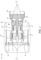
- Figure 1 shows a schematic sectional side view of a gas turbine engine 10 having a principal and rotational axis X-X'.
- the gas turbine engine 10 includes, in axial flow series, an air intake 11, a compressive fan 12 (which may also be referred to as a low-pressure compressor), an intermediate pressure compressor 13, a high-pressure compressor 14, combustion equipment 15, a high-pressure turbine 16, an intermediate pressure turbine 17, a low-pressure turbine 18, and a core exhaust nozzle 19.
- a nacelle 21 generally surrounds the gas turbine engine 10 and defines the air intake 11, a bypass duct 22 and a bypass exhaust nozzle 23.
- the gas turbine engine 10 works in a conventional manner so that the air entering the air intake 11 is accelerated by the compressive fan 12 to produce two air flows: a first air flow A into the intermediate pressure compressor 13 and a second air flow B which passes through the bypass duct 22 to provide a propulsive thrust.
- the intermediate pressure compressor 13 compresses the first air flow A directed into it before delivering that air to the high-pressure compressor 14 where further compression takes place.
- the compressed air exhausted from the high-pressure compressor 14 is directed into the combustion equipment 15 where it is mixed with fuel and the mixture combusted.
- the resulting hot combustion products then expand through, and thereby drive the high, intermediate, and low-pressure turbines 16, 17, 18 before being exhausted through the core exhaust nozzle 19 to provide additional propulsive thrust.
- the high, intermediate, and low-pressure turbines 16, 17, 18 respectively drive the high and intermediate pressure compressors, 14, 13, and the compressive fan 12 by suitable interconnecting shafts.
- the gas turbine engine 10 is used in an aircraft.
- the gas turbine engine 10 is an ultra-high bypass ratio engine (UHBPR).
- UHBPR ultra-high bypass ratio engine
- the present invention is equally applicable to aero gas turbine engines, marine gas turbine engines and land-based gas turbine engines.
- Figure 2 is a schematic sectional side view of a portion of a composite article 100.
- the composite article 100 is a part of the gas turbine engine 10 (shown in Figure 1 ).
- the composite article 100 includes a substrate 102 including a major surface 104.
- the substrate 102 is selected from the group consisting of steels, alloys (e.g., iron-based alloys), superalloys, refractory metals, inter-metallics, and ceramic matrix composite materials, such as those based on silicon carbide or alumina.
- the substrate 102 may be a high-temperature material, such as a superalloy. It should be understood that the substrate 102 may include any material based on application requirements.
- Suitable alloys for the substrate 102 may include, but are not limited to, nickel-based superalloys, cobalt-based superalloys, iron-based superalloys, low sulphur nickel-based superalloys, low sulphur cobalt-based superalloys, low sulphur iron-based superalloys, etc.
- Such superalloys may typically include a polycrystalline structure but may have portions with a single-crystal or directionally solidified crystalline structure.
- the substrate 102 may include nickel-based superalloys commercially available under the trademark Inconel ® .
- the substrate 102 may include silicon carbide-silicon carbide (SiC-SiC) matrix composites.
- the composite article 100 further includes a barrier coating 110 for the substrate 102.
- the barrier coating 110 is disposed on the major surface 104 of the substrate 102.
- the barrier coating 110 is a thermal barrier coating (TBC) or an environmental barrier coating (EBC).
- the barrier coating 110 may protect the substrate 102 from hot gases and may increase an operational life of the substrate 102 by preventing failure due to oxidation, corrosion, and thermomechanical fatigue.
- the terms “TBC”, “TBCs”, “EBC” or “EBCs”, generally refer to stabilized ceramics that may sustain a fairly high temperature gradient, such that the substrate 102 may be operated at temperatures higher than a melting point of a material of the substrate 102.
- the barrier coating 110 may be a multi-layered coating, with materials and microstructures of individual layers chosen to achieve an optimal performance of the barrier coating 110.
- the composite article 100 may further include one or more layers (e.g., abradable layers, etc.) above or below the barrier coating 110.
- the barrier coating 110 may cover an entire extent of the major surface 104 in the plane of the composite article 100.
- the barrier coating 110 includes a bond coat layer 112 disposed on the major surface 104 of the substrate 102.
- the bond coat layer 112 may be an oxidation-resistant metallic layer.
- the bond coat layer 112 includes an alloy.
- the alloy includes at least one element selected from the group consisting of aluminium, silicon and chromium in order to form a slow growing oxide scale (e.g., alumina, silica, and chromia).
- the bond coat layer 112 may include silica.
- the barrier coating 110 further includes a thermally grown oxide (TGO) layer 114 disposed on the bond coat layer 112 opposite to the major surface 104 of the substrate 102.
- TGO thermally grown oxide
- the TGO layer 114 may be formed when the bond coat layer 112 is exposed to oxygen at high temperatures. Such a layer may further impede oxidation and hot corrosion of the substrate 102.
- the barrier coating 110 includes at least one top coat layer 116 disposed on the TGO layer 114 opposite to the bond coat layer 112.
- the at least one top coat layer 116 includes a ceramic top coat material 120.
- the bond coat layer 112 may enhance adhesion of the top coat layer 116 to the major surface 104 of the substrate 102 and may reduce a rate of oxidation of the substrate 102.
- the top coat layer 116, the TGO layer 114, and the bond coat layer 112 may be formed using vapour deposition techniques or diffusion-based processes.
- the term "at least one top coat layer 116" is interchangeably used hereinafter as the "top coat layer 116".
- the at least one top coat layer 116 includes a single top coat layer 116.
- the at least one top coat layer 116 may include multiple top coat layers 116 disposed adjacent to each other.
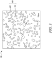
- FIG 3 is a schematic top view of a portion of the top coat layer 116.
- the ceramic top coat material 120 of the top coat layer 116 includes a first phase 122 consisting of a compound having a formula A 2 B 2 O 7 , where A is a rare-earth (RE) element, B is selected from the group consisting of zirconium, hafnium and titanium, and O is oxygen.
- the ceramic top coat material 120 further incudes a second phase 124 dispersed in the first phase 122 and consisting of a compound having a formula CDO 4 , where C is a rare-earth element, D is niobium or tantalum, and O is oxygen.
- the ceramic top coat material 120 includes greater than 0 mole (mol.)% and less than 100 mol.% of the second phase 124. In some embodiments, the ceramic top coat material 120 may include greater than 10 mol.%, greater than 30 mol.%, greater than 50 mol.%, greater than 70 mol.%, or greater than 90 mol.% of the second phase 124. In some embodiments, the first phase 122 and the second phase 124 together form 100% by weight of the ceramic top coat material 120.
- each of A and C is selected from the group consisting of gadolinium, lanthanum and yttrium.
- A is lanthanum and C is gadolinium.
- the first phase 122 may consist of La 2 Zr 2 O 7 and the second phase 124 may consist of GdNbO 4 .
- Another example of the first phase 122 of the ceramic top coat material 120 may include gadolinium zirconate (Gd 2 Zr 2 O 7 ).
- each of A and C is lanthanum.
- the first phase 122 consisting of La 2 Zr 2 O 7 and the second phase 124 consisting of LaNbO 4 may be obtained.
- D is niobium.
- the ceramic top coat material 120 may include lanthanum magnesium hexa-aluminate (LaMgAl 11 O 19 ) or strontium zirconium trioxide (SrZrOa).
- the ceramic top coat material 120 may also include one or more materials from the group consisting of yttrium monosilicate, yttrium disilicate, rare-earth silicates (both rare-earth monosilicates and rare-earth disilicates), alkaline-earth aluminosilicates, such as barium-strontium-aluminosilicate, niobium oxide, tantalum oxide, zirconium oxide, hafnium oxide, yttrium oxide, titanium oxide, mullite, rare-earth oxides, magnesium-spinel (Mg-spinel), such as magnesium aluminate spinel (MgAl 2 O 4 spinel), and mixtures and compounds thereof.
- Mg-spinel magnesium-spine
- the ceramic top coat material 120 may include a variety of metal sources including, but are not limited to, aluminium, chromium, tantalum, niobium, silicon, molybdenum, hafnium, titanium, zirconium, platinum, palladium, gold, and mixtures and alloys thereof.
- the ceramic top coat material 120 includes a two-phase material, i.e., a material including the first phase 122 and the second phase 124.
- a two-phase material i.e., a material including the first phase 122 and the second phase 124.
- presence of the second phase 124 dispersed in the first phase 122 may result in an improved fracture toughness of the ceramic top coat material 120 by virtue of the interface between the first phase 122 and the second phase 124.
- the improvement in the fracture toughness may be attributed to, e.g., crack bridging mechanisms, crack shielding mechanisms, etc.
- the fracture toughness of the ceramic top coat material 120 may increase in proportion to an increase in the mol.% of the second phase 124 dispersed in the first phase 122.
- At least one of the first phase 122 and the second phase 124 is configured to react with molten silicates, such as calcium-magnesium-alumino-silicates (CMAS).
- CMAS calcium-magnesium-alumino-silicates
- the first phase 122 and/or the second phase 124 is configured to react with CMAS when CMAS deposits and melts on the surface of the barrier coating 110 (shown in Figure 2 ), thereby forming RE-apatite phases. This may resist further CMAS penetration into the barrier coating 110. Since the first phase 122 and/or the second phase 124 may react with calcium-magnesium-alumino-silicates (CMAS) and form RE-apatite phases, protection against CMAS is also maintained by the barrier coating 110 of the present invention.
- CMAS calcium-magnesium-alumino-silicates
- RE-cations i.e., element A
- element A RE-cations with a large radius in the ceramic top coat material 120 as this may promote a larger volume of the RE-apatite phase during early stage of reaction with CMAS in order to limit further infiltration of CMAS into the barrier coating 110.
- Figure 4 is a schematic sectional side view of a component 200 of the gas turbine engine 10 (shown in Figure 1 ) illustrating a coating process.
- the component 200 includes a substrate 202 having a major surface 204.
- the substrate 202 may include a material selected from the group consisting of steels, alloys (e.g., iron-based alloys), superalloys, refractory metals, inter-metallics, and ceramic matrix composite materials, such as those based on silicon carbide or alumina.
- the substrate 202 may be a superalloy.
- Figure 5 is a flow chart illustrating a method 210 for manufacturing the component 200 (shown in Figure 4 ) of the gas turbine engine 10 (shown in Figure 1 ).
- the method 210 includes coating the component 200 with the barrier coating 110, e.g., using a coating head 206.
- various layers of the barrier coating 110 may be sequentially coated on the major surface 204 of the component 200 using the coating head 206.
- the component 200 is coated with the barrier coating 110 using at least one of electron-beam physical vapour deposition (EB-PVD), suspension plasma spraying (SPS), solution precursor plasma spraying (SPPS), air plasma spraying (APS), and high-velocity oxygen fuel (HVOF) process.
- EB-PVD electron-beam physical vapour deposition
- SPS suspension plasma spraying
- SPPS solution precursor plasma spraying
- APS air plasma spraying
- HVOF high-velocity oxygen fuel
- gadolinium niobate (GdNbO 4 ) powders were prepared by a solid state reaction.
- the raw niobium oxide (Nb 2 O 5 , Sigma Aldrich, UK, 99.99% purity) and gadolinium oxide powders (Gd 2 O 3 , Sigma Aldrich, UK, 99.99% purity) were calcined at 1000 degree Celsius (°C) for 4 hours (h) to remove moisture, hydroxides, and carbonates.
- the raw powders were mixed stoichiometrically, and ball milled with zirconia media in ethanol for 24 hours (h) to achieve uniformity.
- the suspension was then dried overnight in the oven at 80 °C. After that, the dried mixture was pre-sintered at 1250 °C for 10 h and then grinded to obtain GdNbO 4 powders.
- the 0.5 GdNbO 4 / 0.5 La 2 Zr 2 O 7 composite was also sintered by a spark plasma sintering (SPS) method at 1600 °C under a pressure of 40 megapascal (MPa) for 10 minutes (mins).
- SPS spark plasma sintering
- the heating and cooling rates were 100 °C/min and 200 °C/min, respectively.
- Table 1 summarizes chemical composition corresponding to various points shown in Figures 6A-6E (in at.%).
- Table 1 Point Zirconium (Zr) Lanthanum (La) Niobium (Nb) Gadolinium (Gd) Oxygen (O) Main Phase 301 21.6 20.7 - - 57.7 La 2 Zr 2 O 7 302 9.3 25.9 3.3 1.0 60.5 La 2 O 3 303 22.5 21.3 4.1 1.2 50.9 La 2 Zr 2 O 7 304 3.9 17.3 18.2 2.1 58.6 LaNbO 4 305 18.2 16.2 5.7 3.4 56.5 La 2 Zr 2 O 7 306 0.4 14.9 20.1 3.8 60.7 LaNbO 4 307 16.4 12.1 5.2 7.3 58.9 La 2 Zr 2 O 7 308 12.6 12.5 5.6 6.3 63.0 La 2 Zr 2 O 7
- Figures 7A-7E are micrographs showing indentation of the surface of x GdNbO 4 / (1-x) La 2 Zr 2 O 7 composites shown in Figures 6A-6E using Berkovich pyramid indenter.
- fracture toughness is ascribed to crack bridging and shielding mechanisms as shown by a region 312 and a region 314, respectively, in Figure 7D . However, it should be understood that the fracture toughness may be improved through various other toughening mechanisms.
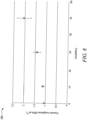
- Figure 8 is a schematic graph 320 showing fracture toughness of lanthanum zirconate (La 2 Zr 2 O 7 ) with an increasing mole fraction of gadolinium niobate (GdNbO 4 ) as determined using Berkovich pyramid indenter.
- the graph 320 shows that the fracture toughness of lanthanum zirconate (La 2 Zr 2 O 7 ) improves with the increasing mole fraction of gadolinium niobate (GdNbO 4 ).
- region 340 shows XRD reflection of 0.5 GdNbO 4 / 0.5 La 2 Zr 2 O 7 composite produced via SPS at 1600 °C for 10 mins.
- the top layer 108 may include a ceramic material, such as yttria-stabilized zirconia (YSZ), however, any other ceramic material may be utilized.
- YSZ yttria-stabilized zirconia
- Alternative stabilizers for tetragonal phase in zirconia may include cerium (IV) oxide (CeO2), magnesium oxide (MgO), calcium oxide (CaO), or other oxides.
- YSZ may include additional elements such as, but are not limited to, titanium dioxide (TiO 2 ), scandium oxide (Sc 2 O 3 ), aluminium oxide (Al 2 O 3 ), etc.
- multi-layer and composition-graded protective coatings composed of the aforementioned materials may be also utilized.
Landscapes
- Chemical & Material Sciences (AREA)
- Engineering & Computer Science (AREA)
- Organic Chemistry (AREA)
- Materials Engineering (AREA)
- Ceramic Engineering (AREA)
- Chemical Kinetics & Catalysis (AREA)
- Inorganic Chemistry (AREA)
- Mechanical Engineering (AREA)
- Metallurgy (AREA)
- Physics & Mathematics (AREA)
- Plasma & Fusion (AREA)
- Structural Engineering (AREA)
- Composite Materials (AREA)
- Manufacturing & Machinery (AREA)
- Turbine Rotor Nozzle Sealing (AREA)
Abstract
Description
- The present invention generally relates to a barrier coating for a substrate that has a major surface, for example a gas turbine engine component.
- Thermal and environmental barrier coatings are often applied on surfaces of high temperature components of gas turbine engines, such as combustors, turbines, exhaust sections, etc. Such coatings may insulate the high temperature components in addition to protecting the coated components from oxidation and corrosion at high temperatures, and mechanical damage during operation of the gas turbine engine. Conventional materials used for such coatings may include yttria stabilised zirconia, low conductivity stabilised zirconia, gadolinium zirconate, ytterbium silicates, etc.
- Gadolinium zirconate may be advantageous over other materials due to its propensity to react with calcium-magnesium-alumino-silicates (CMAS), that typically deposit on the coated components during operation of the gas turbine engine, to form a rare earth (RE)-apatite layer comprising, e.g., gadolinium calcium silicate or Gd8Ca2(SiO4)6O2. Formation of an apatite layer may decelerate further CMAS penetration into the coating.
- However, gadolinium zirconate may be less suitable as a coating material due its lower fracture toughness, thereby increasing susceptibility of the coating to cold-shock delamination during engine shutdown after the CMAS infiltration and the chemical reaction with CMAS. This may result in loss of the CMAS infiltrated and reacted layer (i.e., the RE-apatite layer) causing further degradation and loss of the coating. Additionally, due to lower fracture toughness, the coating may be more susceptible to ballistic impact damage, resulting in increased degradation during operation of the gas turbine engine.
- The present invention provides a barrier coating, a composite article, a gas turbine engine, and a method for manufacturing a component of a gas turbine engine, as set out in the appended claims. Optional features are included in the dependent claims.
- According to a first aspect, there is provided a barrier coating for a substrate including a major surface. The barrier coating includes a bond coat layer disposed on the major surface of the substrate. The barrier coating further includes a thermally grown oxide (TGO) layer disposed on the bond coat layer opposite to the major surface of the substrate. The barrier coating further includes at least one top coat layer disposed on the TGO layer opposite to the bond coat layer. The at least one top coat layer includes a ceramic top coat material. The ceramic top coat material includes a first phase consisting of a compound having a formula A2B2O7, where A is one or more rare-earth element (RE), B is selected from the group consisting of zirconium, hafnium and titanium, and O is oxygen. The ceramic top coat material further includes a second phase dispersed in the first phase and consisting of a compound having a formula CDO4, where C is one or more rare-earth element, D is selected from the group consisting of niobium or tantalum, and O is oxygen.
- The ceramic top coat material of the barrier coating includes a two-phase material, i.e., a material including the first phase and the second phase. As compared to conventional ceramic top coat materials consisting only of the first phase, presence of the second phase dispersed in the first phase may result in an improved fracture toughness of the ceramic top coat material by virtue of the interface between the first phase and the second phase. The second phase is dispersed in the first phase so as to form a material, i.e. the ceramic top coat material, that has desirable fracture toughness. The improvement in the fracture toughness may be attributed to, e.g., crack bridging mechanisms, crack shielding mechanisms, etc. Further, since the first phase and/or the second phase may react with calcium-magnesium-alumino-silicates (CMAS) and form RE-apatite phases, protection against CMAS is also maintained with the ceramic top coat material.
- In some embodiments, the ceramic top coat material consists of: the first phase that consists of a compound having a formula A2B2O7, where A is one or more rare-earth element (RE), B is selected from the group consisting of zirconium, hafnium and titanium, and O is oxygen, and the second phase that is dispersed in the first phase and consists of a compound having a formula CDO4, where C is one or more rare-earth element, D is selected from the group consisting of niobium or tantalum, and O is oxygen.
- In some embodiments, each of A and C is selected from the group consisting of gadolinium, lanthanum and yttrium. Presence of these elements in the first phase and/or the second phase may allow the first phase and/or the second phase to react with CMAS, that typically deposit on the ceramic top coat material, to form RE-apatite phases. It may be preferable to use RE-cations (i.e., element A) with a large radius in the ceramic top coat material as this may promote a larger volume of the RE-apatite phase during early stage of reaction with CMAS in order to limit further infiltration of CMAS into the ceramic top coat material.
- In some embodiments, A is lanthanum and C is gadolinium.
- In some embodiments, each of A and C is lanthanum.
- In some embodiments, D is niobium.
- In some embodiments, the ceramic top coat material of the barrier coating includes greater than 0 mol.% and less than 100 mol.% of the second phase. The fracture toughness of the ceramic top coat material may increase in proportion to an increase in the mol.% of the second phase dispersed in the first phase.
- In some embodiments, at least one of the first phase and the second phase of the ceramic top coat material is configured to react with molten silicates. The first phase and/or the second phase may react with the CMAS to form the RE-apatite phases that may resist further CMAS penetration into the ceramic top coat material.
- In some embodiments, the first phase and the second phase together form 100% by weight of the ceramic top coat material.
- In some embodiments, the bond coat layer of the barrier coating includes an alloy. In some embodiments, the alloy includes at least one element selected from the group consisting of aluminium, silicon and chromium. Such a bond coat layer may act as an adherent layer for the thermally grown oxide (TGO) layer.
- In some embodiments, the barrier coating is a thermal barrier coating or an environmental barrier coating. Thus, the barrier coating may protect the substrate from hot gases and may increase an operational life of the substrate by preventing failure due to oxidation, corrosion, and thermomechanical fatigue.
- According to a second aspect, there is provided a composite article. The composite article includes a substrate that has a major surface. The composite article further includes the barrier coating of the first aspect disposed on the major surface of the substrate. The barrier coating may protect the major surface of the substrate from hot gases and may increase an operational life of the composite article.
- In some embodiments, the substrate is selected from the group consisting of steels, alloys, superalloys, refractory metals, inter-metallics, and ceramic matrix composite materials.
- According to a third aspect, there is provided a gas turbine engine including the composite article of second aspect.
- According to a fourth aspect, there is provided a method for manufacturing a component of a gas turbine engine. The method includes coating the component with the barrier coating of the first aspect.
- In some embodiments, the component is coated with the barrier coating using at least one of electron-beam physical vapour deposition (EB-PVD), suspension plasma spraying (SPS), solution precursor plasma spraying (SPPS), air plasma spraying (APS), and high-velocity oxygen fuel (HVOF) process.
- The skilled person will appreciate that except where mutually exclusive, a feature or parameter described in relation to any one of the above aspects may be applied to any other aspect. Furthermore, except where mutually exclusive, any feature or parameter described herein may be applied to any aspect and/or combined with any other feature or parameter described herein.
- Embodiments will now be described by way of example only, with reference to the Figures, in which:
-
Figure 1 is a schematic sectional side view of a gas turbine engine; -
Figure 2 is a schematic sectional side view of a portion of a composite article that includes a barrier coating disposed on a major surface of a substrate; -
Figure 3 is a schematic top view of a portion of a top coat layer of the composite article; -
Figure 4 is a schematic sectional side view of a component of the gas turbine engine illustrating a coating process; -
Figure 5 is a flow chart illustrating a method for manufacturing the component of the gas turbine engine; -
Figure 6A-6E are micrographs of a portion of a surface of x GdNbO4 / (1-x) La2Zr2O7 composites (where x = 0, 0.1, 0.3, and 0.5; -
Figures 7A-7E are micrographs showing indentation of the surface of x GdNbO4 / (1-x) La2Zr2O7 composites shown inFigures 6A-6E using Berkovich pyramid indenter; -
Figure 8 is a schematic graph showing fracture toughness of lanthanum zirconate (La2Zr2O7) with an increasing mole fraction of gadolinium niobate (GdNbO4) as determined using Berkovich pyramid indenter; and -
Figure 9 is a schematic graph showing x-ray diffraction (XRD) reflections of x GdNbO4 / (1-x) La2Zr2O7 composites (where x = 0, 0.1, 0.3, 0.5). - Aspects and embodiments of the present invention will now be discussed with reference to the accompanying figures. Further aspects and embodiments will be apparent to those skilled in the art.
- Chemical elements are discussed in the present disclosure using their common chemical abbreviations, such as commonly found on a periodic table of elements. For example, hydrogen is represented by its common chemical abbreviation H; helium is represented by its common chemical abbreviation He; and so forth.
- As used herein, the term "rare-earth (RE) element" refers to a Group IIIB element (i.e., a lanthanoid) or yttrium in the periodic table of elements. The group of elements known as rare-earth elements includes, for example, elements 57-71 (i.e., La, Ce, Pr, Nd, Pm, Sm, Eu, Gd, Tb, Dy, Ho, Er, Tm, Yb, and Lu) and yttrium.
-
Figure 1 shows a schematic sectional side view of agas turbine engine 10 having a principal and rotational axis X-X'. Thegas turbine engine 10 includes, in axial flow series, anair intake 11, a compressive fan 12 (which may also be referred to as a low-pressure compressor), anintermediate pressure compressor 13, a high-pressure compressor 14,combustion equipment 15, a high-pressure turbine 16, anintermediate pressure turbine 17, a low-pressure turbine 18, and acore exhaust nozzle 19. Anacelle 21 generally surrounds thegas turbine engine 10 and defines theair intake 11, abypass duct 22 and abypass exhaust nozzle 23. - The
gas turbine engine 10 works in a conventional manner so that the air entering theair intake 11 is accelerated by thecompressive fan 12 to produce two air flows: a first air flow A into theintermediate pressure compressor 13 and a second air flow B which passes through thebypass duct 22 to provide a propulsive thrust. Theintermediate pressure compressor 13 compresses the first air flow A directed into it before delivering that air to the high-pressure compressor 14 where further compression takes place. - The compressed air exhausted from the high-
pressure compressor 14 is directed into thecombustion equipment 15 where it is mixed with fuel and the mixture combusted. The resulting hot combustion products then expand through, and thereby drive the high, intermediate, and low-pressure turbines core exhaust nozzle 19 to provide additional propulsive thrust. The high, intermediate, and low-pressure turbines compressive fan 12 by suitable interconnecting shafts. - In some embodiments, the
gas turbine engine 10 is used in an aircraft. In some embodiments, thegas turbine engine 10 is an ultra-high bypass ratio engine (UHBPR). In addition, the present invention is equally applicable to aero gas turbine engines, marine gas turbine engines and land-based gas turbine engines. -
Figure 2 is a schematic sectional side view of a portion of acomposite article 100. In some embodiments, thecomposite article 100 is a part of the gas turbine engine 10 (shown inFigure 1 ). In some embodiments, thecomposite article 100 includes asubstrate 102 including amajor surface 104. In some embodiments, thesubstrate 102 is selected from the group consisting of steels, alloys (e.g., iron-based alloys), superalloys, refractory metals, inter-metallics, and ceramic matrix composite materials, such as those based on silicon carbide or alumina. In some embodiments, thesubstrate 102 may be a high-temperature material, such as a superalloy. It should be understood that thesubstrate 102 may include any material based on application requirements. - Suitable alloys for the
substrate 102 may include, but are not limited to, nickel-based superalloys, cobalt-based superalloys, iron-based superalloys, low sulphur nickel-based superalloys, low sulphur cobalt-based superalloys, low sulphur iron-based superalloys, etc. Such superalloys may typically include a polycrystalline structure but may have portions with a single-crystal or directionally solidified crystalline structure. In some embodiments, thesubstrate 102 may include nickel-based superalloys commercially available under the trademark Inconel®. In some embodiments, thesubstrate 102 may include silicon carbide-silicon carbide (SiC-SiC) matrix composites. - The
composite article 100 further includes abarrier coating 110 for thesubstrate 102. Specifically, thebarrier coating 110 is disposed on themajor surface 104 of thesubstrate 102. In some embodiments, thebarrier coating 110 is a thermal barrier coating (TBC) or an environmental barrier coating (EBC). In some embodiments, thebarrier coating 110 may protect thesubstrate 102 from hot gases and may increase an operational life of thesubstrate 102 by preventing failure due to oxidation, corrosion, and thermomechanical fatigue. - As used herein, the terms "TBC", "TBCs", "EBC" or "EBCs", generally refer to stabilized ceramics that may sustain a fairly high temperature gradient, such that the
substrate 102 may be operated at temperatures higher than a melting point of a material of thesubstrate 102. In some embodiments, thebarrier coating 110 may be a multi-layered coating, with materials and microstructures of individual layers chosen to achieve an optimal performance of thebarrier coating 110. In some embodiments, thecomposite article 100 may further include one or more layers (e.g., abradable layers, etc.) above or below thebarrier coating 110. In some embodiments, thebarrier coating 110 may cover an entire extent of themajor surface 104 in the plane of thecomposite article 100. - In some embodiments, the
barrier coating 110 includes abond coat layer 112 disposed on themajor surface 104 of thesubstrate 102. In some embodiments, thebond coat layer 112 may be an oxidation-resistant metallic layer. In some embodiments, thebond coat layer 112 includes an alloy. In some embodiments, the alloy includes at least one element selected from the group consisting of aluminium, silicon and chromium in order to form a slow growing oxide scale (e.g., alumina, silica, and chromia). In some embodiments, thebond coat layer 112 may include an aluminium containing alloy, such as MCrAlY, where M = Nickel (Ni) and/or Cobalt (Co), or an aluminium-based intermetallic, such as nickel aluminide, containing varying amounts of platinum (Pt) and/or rare earth elements, such hafnium (Hf). In some embodiments, thebond coat layer 112 may include silica. - In some embodiments, the
barrier coating 110 further includes a thermally grown oxide (TGO)layer 114 disposed on thebond coat layer 112 opposite to themajor surface 104 of thesubstrate 102. In some embodiments, theTGO layer 114 may be formed when thebond coat layer 112 is exposed to oxygen at high temperatures. Such a layer may further impede oxidation and hot corrosion of thesubstrate 102. - The
barrier coating 110 includes at least onetop coat layer 116 disposed on theTGO layer 114 opposite to thebond coat layer 112. The at least onetop coat layer 116 includes a ceramictop coat material 120. In some embodiments, thebond coat layer 112 may enhance adhesion of thetop coat layer 116 to themajor surface 104 of thesubstrate 102 and may reduce a rate of oxidation of thesubstrate 102. In some embodiments, thetop coat layer 116, theTGO layer 114, and thebond coat layer 112 may be formed using vapour deposition techniques or diffusion-based processes. The term "at least onetop coat layer 116" is interchangeably used hereinafter as the "top coat layer 116". In the illustrated embodiment ofFigure 2 , the at least onetop coat layer 116 includes a singletop coat layer 116. However, in some other embodiments, the at least onetop coat layer 116 may include multipletop coat layers 116 disposed adjacent to each other. -
Figure 3 is a schematic top view of a portion of thetop coat layer 116. The ceramictop coat material 120 of thetop coat layer 116 includes afirst phase 122 consisting of a compound having a formula A2B2O7, where A is a rare-earth (RE) element, B is selected from the group consisting of zirconium, hafnium and titanium, and O is oxygen. The ceramictop coat material 120 further incudes asecond phase 124 dispersed in thefirst phase 122 and consisting of a compound having a formula CDO4, where C is a rare-earth element, D is niobium or tantalum, and O is oxygen. - In some embodiments, the ceramic
top coat material 120 includes greater than 0 mole (mol.)% and less than 100 mol.% of thesecond phase 124. In some embodiments, the ceramictop coat material 120 may include greater than 10 mol.%, greater than 30 mol.%, greater than 50 mol.%, greater than 70 mol.%, or greater than 90 mol.% of thesecond phase 124. In some embodiments, thefirst phase 122 and thesecond phase 124 together form 100% by weight of the ceramictop coat material 120. - In some embodiments, each of A and C is selected from the group consisting of gadolinium, lanthanum and yttrium. In some embodiments, A is lanthanum and C is gadolinium. For example, the
first phase 122 may consist of La2Zr2O7 and thesecond phase 124 may consist of GdNbO4. Another example of thefirst phase 122 of the ceramictop coat material 120 may include gadolinium zirconate (Gd2Zr2O7). In some embodiments, each of A and C is lanthanum. For example, during preparation of the ceramictop coat material 120 through pressure-less sintering, thefirst phase 122 consisting of La2Zr2O7 and thesecond phase 124 consisting of LaNbO4 may be obtained. In some embodiments, D is niobium. - In some embodiments, the ceramic
top coat material 120 may include lanthanum magnesium hexa-aluminate (LaMgAl11O19) or strontium zirconium trioxide (SrZrOa). In some embodiments, the ceramictop coat material 120 may also include one or more materials from the group consisting of yttrium monosilicate, yttrium disilicate, rare-earth silicates (both rare-earth monosilicates and rare-earth disilicates), alkaline-earth aluminosilicates, such as barium-strontium-aluminosilicate, niobium oxide, tantalum oxide, zirconium oxide, hafnium oxide, yttrium oxide, titanium oxide, mullite, rare-earth oxides, magnesium-spinel (Mg-spinel), such as magnesium aluminate spinel (MgAl2O4 spinel), and mixtures and compounds thereof. In some other embodiments, the ceramictop coat material 120 may include a variety of metal sources including, but are not limited to, aluminium, chromium, tantalum, niobium, silicon, molybdenum, hafnium, titanium, zirconium, platinum, palladium, gold, and mixtures and alloys thereof. - The ceramic
top coat material 120 includes a two-phase material, i.e., a material including thefirst phase 122 and thesecond phase 124. As compared to conventional ceramic top coat materials consisting only of thefirst phase 122, presence of thesecond phase 124 dispersed in thefirst phase 122 may result in an improved fracture toughness of the ceramictop coat material 120 by virtue of the interface between thefirst phase 122 and thesecond phase 124. The improvement in the fracture toughness may be attributed to, e.g., crack bridging mechanisms, crack shielding mechanisms, etc. The fracture toughness of the ceramictop coat material 120 may increase in proportion to an increase in the mol.% of thesecond phase 124 dispersed in thefirst phase 122. - In some embodiments, at least one of the
first phase 122 and thesecond phase 124 is configured to react with molten silicates, such as calcium-magnesium-alumino-silicates (CMAS). In other words, thefirst phase 122 and/or thesecond phase 124 is configured to react with CMAS when CMAS deposits and melts on the surface of the barrier coating 110 (shown inFigure 2 ), thereby forming RE-apatite phases. This may resist further CMAS penetration into thebarrier coating 110. Since thefirst phase 122 and/or thesecond phase 124 may react with calcium-magnesium-alumino-silicates (CMAS) and form RE-apatite phases, protection against CMAS is also maintained by thebarrier coating 110 of the present invention. It may be preferable to use RE-cations (i.e., element A) with a large radius in the ceramictop coat material 120 as this may promote a larger volume of the RE-apatite phase during early stage of reaction with CMAS in order to limit further infiltration of CMAS into thebarrier coating 110. -
Figure 4 is a schematic sectional side view of acomponent 200 of the gas turbine engine 10 (shown inFigure 1 ) illustrating a coating process. In some embodiments, thecomponent 200 includes asubstrate 202 having amajor surface 204. In some embodiments, thesubstrate 202 may include a material selected from the group consisting of steels, alloys (e.g., iron-based alloys), superalloys, refractory metals, inter-metallics, and ceramic matrix composite materials, such as those based on silicon carbide or alumina. In some embodiments, thesubstrate 202 may be a superalloy. -
Figure 5 is a flow chart illustrating amethod 210 for manufacturing the component 200 (shown inFigure 4 ) of the gas turbine engine 10 (shown inFigure 1 ). With reference toFigures 2 ,4 and5 , atstep 212, themethod 210 includes coating thecomponent 200 with thebarrier coating 110, e.g., using acoating head 206. In some embodiments, various layers of thebarrier coating 110 may be sequentially coated on themajor surface 204 of thecomponent 200 using thecoating head 206. - In some embodiments, the
component 200 is coated with thebarrier coating 110 using at least one of electron-beam physical vapour deposition (EB-PVD), suspension plasma spraying (SPS), solution precursor plasma spraying (SPPS), air plasma spraying (APS), and high-velocity oxygen fuel (HVOF) process. However, it should be understood that any known method may be utilized for coating thecomponent 200 with thebarrier coating 110. - First, gadolinium niobate (GdNbO4) powders were prepared by a solid state reaction. The raw niobium oxide (Nb2O5, Sigma Aldrich, UK, 99.99% purity) and gadolinium oxide powders (Gd2O3, Sigma Aldrich, UK, 99.99% purity) were calcined at 1000 degree Celsius (°C) for 4 hours (h) to remove moisture, hydroxides, and carbonates. Then the raw powders were mixed stoichiometrically, and ball milled with zirconia media in ethanol for 24 hours (h) to achieve uniformity. The suspension was then dried overnight in the oven at 80 °C. After that, the dried mixture was pre-sintered at 1250 °C for 10 h and then grinded to obtain GdNbO4 powders.
- Second, lanthanum zirconate (La2Zr2O7) and x mol.% (where x = 0, 10, 30, 50) GdNbO4 powders were mixed by ball milling for 24 h with zirconia media. The obtained suspension was dried at 80 °C overnight, followed by sieving via 63 micrometres (µm) sieve. Then the powders of x GdNbO4 / (1-x) La2Zr2O7 (where x=0, 0.1, 0.3, 0.5) were cold-pressed under uniaxial pressure into green bulks (
φ 6 millimetre or mm × 2 mm discs). Ultimately, the green bulks were pressure-less sintered at 1600 °C for 12 h to obtain dense specimens. Moreover, the 0.5 GdNbO4 / 0.5 La2Zr2O7 composite was also sintered by a spark plasma sintering (SPS) method at 1600 °C under a pressure of 40 megapascal (MPa) for 10 minutes (mins). The heating and cooling rates were 100 °C/min and 200 °C/min, respectively. -
Figures 6A-6E are micrographs of a portion of a surface of x GdNbO4 / (1-x) La2Zr2O7 composites. Specifically,Figures 6A-6D are micrographs of pressure-less sintered x GdNbO4 / (1-x) La2Zr2O7 composites at 1600 °C for 12 h, where x = 0, x = 0.1, x = 0.3, and x = 0.5; respectively, whileFigure 6E is the micrograph of 0.5 GdNbO4 / 0.5 La2Zr2O7 composite produced via SPS at 1600 °C for 10 mins. - Table 1 summarizes chemical composition corresponding to various points shown in
Figures 6A-6E (in at.%).Table 1 Point Zirconium (Zr) Lanthanum (La) Niobium (Nb) Gadolinium (Gd) Oxygen (O) Main Phase 301 21.6 20.7 - - 57.7 La2Zr2O7 302 9.3 25.9 3.3 1.0 60.5 La2O3 303 22.5 21.3 4.1 1.2 50.9 La2Zr2O7 304 3.9 17.3 18.2 2.1 58.6 LaNbO 4305 18.2 16.2 5.7 3.4 56.5 La2Zr2O7 306 0.4 14.9 20.1 3.8 60.7 LaNbO 4307 16.4 12.1 5.2 7.3 58.9 La2Zr2O7 308 12.6 12.5 5.6 6.3 63.0 La2Zr2O7 -
Figures 7A-7E are micrographs showing indentation of the surface of x GdNbO4 / (1-x) La2Zr2O7 composites shown inFigures 6A-6E using Berkovich pyramid indenter. - Specifically,
Figures 7A-7D are micrographs showing indentation of the surface of pressure-less sintered x GdNbO4 / (1-x) La2Zr2O7 composites at 1600 °C for 12 h, where x = 0, x = 0.1, x = 0.3, and x = 0.5; respectively, whileFigure 7E is the micrograph showing indentation of the surface of 0.5 GdNbO4 / 0.5 La2Zr2O7 composite produced via SPS at 1600 °C for 10 mins. - Improvement in fracture toughness is ascribed to crack bridging and shielding mechanisms as shown by a
region 312 and aregion 314, respectively, inFigure 7D . However, it should be understood that the fracture toughness may be improved through various other toughening mechanisms. - Table 2 summarizes fracture toughness (in MPa m1/2) of the pressure-less sintered x GdNbO4 / (1-x) La2Zr2O7 (where x = 0, 0.1, 0.3, 0.5) composites at 1600 °C for 12 h and 0.5 GdNbO4 / 0.5 La2Zr2O7 composite produced via SPS at 1600 °C for 10 mins as determined using Berkovich pyramid indenter.
Table 2 Composition x = 0 x = 0.1 x = 0.3 x = 0.5 SPS x = 0.5 Fracture toughness 1.06 ± 0.04 1.10 ± 0.04 1.41 ± 0.17 2.03 ± 0.34 1.12 ± 0.02 -
Figure 8 is aschematic graph 320 showing fracture toughness of lanthanum zirconate (La2Zr2O7) with an increasing mole fraction of gadolinium niobate (GdNbO4) as determined using Berkovich pyramid indenter. Thegraph 320 shows that the fracture toughness of lanthanum zirconate (La2Zr2O7) improves with the increasing mole fraction of gadolinium niobate (GdNbO4). - Further to this, a comparison of the 50 mol.% La2Zr2O7 / 50 mol.% GdNbO4 material with and without the presence of the LaNbO4 phase precipitates shows a higher toughness of 2.03 ± 0.34 MPa.m1/2 with the precipitates compared with 1.12 ± 0.02 MPa.m1/2 without the precipitates.
-
Figure 9 is aschematic graph 330 showing x-ray diffraction (XRD) reflections of x GdNbO4 / (1-x) La2Zr2O7 (where x = 0, 0.1, 0.3, 0.5) composites. Specifically,regions region 340 shows XRD reflection of 0.5 GdNbO4 / 0.5 La2Zr2O7 composite produced via SPS at 1600 °C for 10 mins. - In some embodiments, the top layer 108 may include a ceramic material, such as yttria-stabilized zirconia (YSZ), however, any other ceramic material may be utilized. Alternative stabilizers for tetragonal phase in zirconia may include cerium (IV) oxide (CeO2), magnesium oxide (MgO), calcium oxide (CaO), or other oxides. In some embodiments, YSZ may include additional elements such as, but are not limited to, titanium dioxide (TiO2), scandium oxide (Sc2O3), aluminium oxide (Al2O3), etc. In some embodiments, multi-layer and composition-graded protective coatings composed of the aforementioned materials may be also utilized.
Claims (15)
- A barrier coating (110) for a substrate (102) that has a major surface (104), the barrier coating (110) comprises:a bond coat layer (112) disposed on the major surface (104) of the substrate (102);a thermally grown oxide (TGO) layer (114) disposed on the bond coat layer (112) opposite to the major surface (104) of the substrate (102); andat least one top coat layer (116) disposed on the TGO layer (114) opposite to the bond coat layer (112), the at least one top coat layer (116) comprising a ceramic top coat material (120) comprising:a first phase (122) consisting of a compound having a formula A2B2O7, where A is a rare-earth element, B is selected from the group consisting of zirconium, hafnium and titanium, and O is oxygen; anda second phase (124) dispersed in the first phase and consisting of a compound having a formula CDO4, where C is a rare-earth element, D is niobium or tantalum, and O is oxygen.
- The barrier coating of claim 1, wherein each of A and C is selected from the group consisting of gadolinium, lanthanum and yttrium.
- The barrier coating of claim 2, wherein A is lanthanum and C is gadolinium.
- The barrier coating of claim 2, wherein each of A and C is lanthanum.
- The barrier coating of any preceding claim, wherein D is niobium.
- The barrier coating of any preceding claim, comprising greater than 0 mol.% and less than 100 mol.% of the second phase (124).
- The barrier coating of any preceding claim, wherein at least one of the first phase (122) and the second phase (124) is configured to react with molten silicates.
- The barrier coating of any preceding claim, wherein the first phase (122) and the second phase (124) together form 100% by weight of the ceramic top coat material (120).
- The barrier coating of any preceding claim, wherein the bond coat layer (112) comprises an alloy, and wherein the alloy comprises at least one element selected from the group consisting of aluminium, silicon and chromium.
- The barrier coating of any preceding claim, wherein the barrier coating (110) is a thermal barrier coating or an environmental barrier coating.
- A composite article (100) comprising:a substrate (102) that has a major surface (104); anda barrier coating (110) of any preceding claim disposed on the major surface (104) of the substrate (102).
- The composite article of claim 11, wherein the substrate (102) is selected from the group consisting of steels, alloys, superalloys, refractory metals, inter-metallics, and ceramic matrix composite materials.
- A gas turbine engine (10) including a composite article (100) of claim 11 or 12.
- A method (210) for manufacturing a component (200) of a gas turbine engine (10), the method (210) comprising coating the component (200) with a barrier coating (110) of any one of claims 1 to 10.
- The method of claim 14, wherein the component (200) is coated with the barrier coating (110) using at least one of electron-beam physical vapour deposition (EB-PVD), suspension plasma spraying (SPS), solution precursor plasma spraying (SPPS), air plasma spraying (APS), and high-velocity oxygen fuel (HVOF) process.
Applications Claiming Priority (1)
| Application Number | Priority Date | Filing Date | Title |
|---|---|---|---|
| GBGB2214491.9A GB202214491D0 (en) | 2022-10-03 | 2022-10-03 | Ceramic top coat material for a gas turbine engine |
Publications (1)
| Publication Number | Publication Date |
|---|---|
| EP4349799A1 true EP4349799A1 (en) | 2024-04-10 |
Family
ID=84000076
Family Applications (1)
| Application Number | Title | Priority Date | Filing Date |
|---|---|---|---|
| EP23195094.0A Pending EP4349799A1 (en) | 2022-10-03 | 2023-09-04 | Barrier coating for gas turbine engine components |
Country Status (2)
| Country | Link |
|---|---|
| EP (1) | EP4349799A1 (en) |
| GB (1) | GB202214491D0 (en) |
Cited By (2)
| Publication number | Priority date | Publication date | Assignee | Title |
|---|---|---|---|---|
| CN119528612A (en) * | 2024-11-27 | 2025-02-28 | 清华大学 | Thermal barrier-environmental barrier coating material and preparation method and application thereof, thermal barrier-environmental barrier coating and preparation method thereof |
| CN121086553A (en) * | 2025-08-12 | 2025-12-09 | 武汉海升复合材料有限公司 | Low-heat-conductivity high-emissivity infrared radiation coating, preparation method thereof and coating |
Citations (4)
| Publication number | Priority date | Publication date | Assignee | Title |
|---|---|---|---|---|
| EP3031954A1 (en) * | 2014-12-12 | 2016-06-15 | General Electric Company | Articles for high temperature service |
| US20170321559A1 (en) * | 2016-05-09 | 2017-11-09 | General Electric Company | Thermal barrier system with bond coat barrier |
| CN113173787A (en) * | 2021-03-08 | 2021-07-27 | 江苏大学 | Gadolinium zirconate/gadolinium tantalate composite ceramic and preparation method thereof |
| EP3904555A1 (en) * | 2018-12-29 | 2021-11-03 | Kunming University Of Science And Technology | Ultralimit alloy and preparation method therefor |
-
2022
- 2022-10-03 GB GBGB2214491.9A patent/GB202214491D0/en not_active Ceased
-
2023
- 2023-09-04 EP EP23195094.0A patent/EP4349799A1/en active Pending
Patent Citations (4)
| Publication number | Priority date | Publication date | Assignee | Title |
|---|---|---|---|---|
| EP3031954A1 (en) * | 2014-12-12 | 2016-06-15 | General Electric Company | Articles for high temperature service |
| US20170321559A1 (en) * | 2016-05-09 | 2017-11-09 | General Electric Company | Thermal barrier system with bond coat barrier |
| EP3904555A1 (en) * | 2018-12-29 | 2021-11-03 | Kunming University Of Science And Technology | Ultralimit alloy and preparation method therefor |
| CN113173787A (en) * | 2021-03-08 | 2021-07-27 | 江苏大学 | Gadolinium zirconate/gadolinium tantalate composite ceramic and preparation method thereof |
Non-Patent Citations (1)
| Title |
|---|
| TITOV Y A ET AL: "Synthesis, structure and ferroelectric properties of heteroblock slab phases in La"2Ti"2O"7-LaTaO"4 system", JOURNAL OF ALLOYS AND COMPOUNDS, ELSEVIER SEQUOIA, LAUSANNE, CH, vol. 316, no. 1-2, 2 March 2001 (2001-03-02), pages 309 - 315, XP004317542, ISSN: 0925-8388, DOI: 10.1016/S0925-8388(00)01504-8 * |
Cited By (2)
| Publication number | Priority date | Publication date | Assignee | Title |
|---|---|---|---|---|
| CN119528612A (en) * | 2024-11-27 | 2025-02-28 | 清华大学 | Thermal barrier-environmental barrier coating material and preparation method and application thereof, thermal barrier-environmental barrier coating and preparation method thereof |
| CN121086553A (en) * | 2025-08-12 | 2025-12-09 | 武汉海升复合材料有限公司 | Low-heat-conductivity high-emissivity infrared radiation coating, preparation method thereof and coating |
Also Published As
| Publication number | Publication date |
|---|---|
| GB202214491D0 (en) | 2022-11-16 |
Similar Documents
| Publication | Publication Date | Title |
|---|---|---|
| US11149338B2 (en) | Gas turbine engine component coating with self-healing barrier layer | |
| US7429424B2 (en) | Sintering resistant, low conductivity, high stability thermal barrier coating/environmental barrier coating system for a ceramic-matrix composite (CMC) article to improve high temperature capability | |
| EP2553027B1 (en) | Multilayer cmas-resistant barrier coating | |
| EP1400611A1 (en) | Thermal barrier coating material comprising rare earth oxides | |
| EP2189504B1 (en) | Reinforced oxide coatings | |
| EP1218564B1 (en) | In-situ formation of multiphase air plasma sprayed barrier coatings for turbine components | |
| EP1666438B1 (en) | Thermal barrier coating/environmental barrier coating system for a silicon containing substrate to improve high temperature capability | |
| US6296945B1 (en) | In-situ formation of multiphase electron beam physical vapor deposited barrier coatings for turbine components | |
| EP1683775B1 (en) | Thermal/environmental barrier coating with transition layer for silicon comprising materials | |
| EP1640477B1 (en) | High temperature component with thermal barrier coating and gas turbine using the same | |
| US20090184280A1 (en) | Low Thermal Conductivity, CMAS-Resistant Thermal Barrier Coatings | |
| JP6560266B2 (en) | Thermal barrier and environmental coating composition | |
| US20190047253A1 (en) | Adhesion promoter layer for joining a high-temperature protection layer to a substrate, and method for producing same | |
| US7326468B2 (en) | Thermal/environmental barrier coating for silicon-comprising materials | |
| EP1683772A2 (en) | Thermal/environmental barrier coating with transition layer for silicon-comprising materials | |
| US20060166019A1 (en) | Thermal/environmental barrier coating for silicon-comprising materials | |
| EP4223726B1 (en) | Bond coat including metal oxides and oxygen getters | |
| EP1793010B1 (en) | Ceramic coating material | |
| EP4722184A1 (en) | Thermal barrier coating for gas turbine engine components | |
| RU2851649C1 (en) | Gas turbine blade with multilayer heat shielding coating | |
| EP4711352A1 (en) | Ceramic coatings with sintering agents | |
| WO2014184906A1 (en) | Heat shield coating member |
Legal Events
| Date | Code | Title | Description |
|---|---|---|---|
| PUAI | Public reference made under article 153(3) epc to a published international application that has entered the european phase |
Free format text: ORIGINAL CODE: 0009012 |
|
| STAA | Information on the status of an ep patent application or granted ep patent |
Free format text: STATUS: THE APPLICATION HAS BEEN PUBLISHED |
|
| AK | Designated contracting states |
Kind code of ref document: A1 Designated state(s): AL AT BE BG CH CY CZ DE DK EE ES FI FR GB GR HR HU IE IS IT LI LT LU LV MC ME MK MT NL NO PL PT RO RS SE SI SK SM TR |
|
| STAA | Information on the status of an ep patent application or granted ep patent |
Free format text: STATUS: REQUEST FOR EXAMINATION WAS MADE |
|
| 17P | Request for examination filed |
Effective date: 20240802 |
|
| RBV | Designated contracting states (corrected) |
Designated state(s): AL AT BE BG CH CY CZ DE DK EE ES FI FR GB GR HR HU IE IS IT LI LT LU LV MC ME MK MT NL NO PL PT RO RS SE SI SK SM TR |