EP4349750A1 - Conveyance roller mechanism and printer - Google Patents
Conveyance roller mechanism and printer Download PDFInfo
- Publication number
- EP4349750A1 EP4349750A1 EP22816010.7A EP22816010A EP4349750A1 EP 4349750 A1 EP4349750 A1 EP 4349750A1 EP 22816010 A EP22816010 A EP 22816010A EP 4349750 A1 EP4349750 A1 EP 4349750A1
- Authority
- EP
- European Patent Office
- Prior art keywords
- roller
- support member
- support
- unit
- feed roller
- Prior art date
- Legal status (The legal status is an assumption and is not a legal conclusion. Google has not performed a legal analysis and makes no representation as to the accuracy of the status listed.)
- Pending
Links
Images


Classifications
-
- B—PERFORMING OPERATIONS; TRANSPORTING
- B65—CONVEYING; PACKING; STORING; HANDLING THIN OR FILAMENTARY MATERIAL
- B65H—HANDLING THIN OR FILAMENTARY MATERIAL, e.g. SHEETS, WEBS, CABLES
- B65H23/00—Registering, tensioning, smoothing or guiding webs
- B65H23/04—Registering, tensioning, smoothing or guiding webs longitudinally
- B65H23/16—Registering, tensioning, smoothing or guiding webs longitudinally by weighted or spring-pressed movable bars or rollers
-
- B—PERFORMING OPERATIONS; TRANSPORTING
- B65—CONVEYING; PACKING; STORING; HANDLING THIN OR FILAMENTARY MATERIAL
- B65H—HANDLING THIN OR FILAMENTARY MATERIAL, e.g. SHEETS, WEBS, CABLES
- B65H20/00—Advancing webs
- B65H20/02—Advancing webs by friction roller
-
- B—PERFORMING OPERATIONS; TRANSPORTING
- B65—CONVEYING; PACKING; STORING; HANDLING THIN OR FILAMENTARY MATERIAL
- B65H—HANDLING THIN OR FILAMENTARY MATERIAL, e.g. SHEETS, WEBS, CABLES
- B65H2301/00—Handling processes for sheets or webs
- B65H2301/40—Type of handling process
- B65H2301/44—Moving, forwarding, guiding material
- B65H2301/443—Moving, forwarding, guiding material by acting on surface of handled material
- B65H2301/4431—Moving, forwarding, guiding material by acting on surface of handled material by means with operating surfaces contacting opposite faces of material
- B65H2301/44318—Moving, forwarding, guiding material by acting on surface of handled material by means with operating surfaces contacting opposite faces of material between rollers
-
- B—PERFORMING OPERATIONS; TRANSPORTING
- B65—CONVEYING; PACKING; STORING; HANDLING THIN OR FILAMENTARY MATERIAL
- B65H—HANDLING THIN OR FILAMENTARY MATERIAL, e.g. SHEETS, WEBS, CABLES
- B65H2402/00—Constructional details of the handling apparatus
- B65H2402/50—Machine elements
- B65H2402/54—Springs, e.g. helical or leaf springs
-
- B—PERFORMING OPERATIONS; TRANSPORTING
- B65—CONVEYING; PACKING; STORING; HANDLING THIN OR FILAMENTARY MATERIAL
- B65H—HANDLING THIN OR FILAMENTARY MATERIAL, e.g. SHEETS, WEBS, CABLES
- B65H2404/00—Parts for transporting or guiding the handled material
- B65H2404/10—Rollers
- B65H2404/14—Roller pairs
- B65H2404/142—Roller pairs arranged on movable frame
-
- B—PERFORMING OPERATIONS; TRANSPORTING
- B65—CONVEYING; PACKING; STORING; HANDLING THIN OR FILAMENTARY MATERIAL
- B65H—HANDLING THIN OR FILAMENTARY MATERIAL, e.g. SHEETS, WEBS, CABLES
- B65H2515/00—Physical entities not provided for in groups B65H2511/00 or B65H2513/00
- B65H2515/30—Forces; Stresses
-
- B—PERFORMING OPERATIONS; TRANSPORTING
- B65—CONVEYING; PACKING; STORING; HANDLING THIN OR FILAMENTARY MATERIAL
- B65H—HANDLING THIN OR FILAMENTARY MATERIAL, e.g. SHEETS, WEBS, CABLES
- B65H2701/00—Handled material; Storage means
- B65H2701/10—Handled articles or webs
- B65H2701/19—Specific article or web
- B65H2701/192—Labels
-
- B—PERFORMING OPERATIONS; TRANSPORTING
- B65—CONVEYING; PACKING; STORING; HANDLING THIN OR FILAMENTARY MATERIAL
- B65H—HANDLING THIN OR FILAMENTARY MATERIAL, e.g. SHEETS, WEBS, CABLES
- B65H2801/00—Application field
- B65H2801/03—Image reproduction devices
- B65H2801/12—Single-function printing machines, typically table-top machines
Definitions
- the present invention relates to a feed roller mechanism and a printer.
- JP2015-223704A discloses a printer provided with a liner sheet pulling roller that feeds a liner sheet of a label continuous body that is turned by a peeling plate rearward while nipping the liner sheet with an opposing roller.
- the present invention is made in view of such technical problems, and an object thereof is to make it possible to easily set the nipping force between the two rollers to an appropriate nipping force.
- a feed roller mechanism that feeds a continuous paper while nipping the continuous paper between a first roller and a second roller that face each other, the feed roller mechanism comprising: a plate-shaped first support member that supports the first roller; and a plate-shaped second support member that supports the first support member, wherein the first roller nips the continuous paper with the second roller by a deflection reaction force of the first support member.
- the nipping force between the first roller and the second roller is determined by the deflection reaction force of the first support member. Therefore, it is possible to suppress variation in the nipping force due to an assembly error or the like, and it is possible to easily set the nipping force between the first roller and the second roller to an appropriate nipping force.
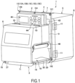
- FIG. 1 is a perspective view of the printer 1 provided with the feed roller mechanism 70.
- the printer 1 includes a central main body unit 2, a printing unit 3, a drive unit (not shown) that drives the printing unit 3, a control unit 4, and a power supply unit 5.
- the printing unit 3 is positioned on one side surface (a front surface) of the central main body unit 2.
- the drive unit, the control unit 4, and the power supply unit 5 are positioned on the other (opposite) side surface (a back surface) of the central main body unit 2.
- FIG. 2 is a perspective view of the printer 1 with a printing unit cover 6, a control unit cover 7, and a power supply unit cover 8 opened.
- the printing unit cover 6 can be opened and closed around a printing unit cover opening and closing shaft 10 provided in a support case 9 of the central main body unit 2.
- the control unit cover 7 can be opened and closed around a control unit cover opening and closing shaft (not shown) provided at one end portion of the central main body unit 2.
- the power supply unit cover 8 can be opened and closed around a power unit cover opening and closing shaft 11 provided at the other end portion of the central main body unit 2.
- a support link 12 is provided between the printing unit cover 6 and the support case 9 in a manner of bending as the printing unit cover 6 opens and closes. As a result, an open state of the printing unit cover 6 can be maintained. By providing a cover-side magnet 13 and a case-side magnet 14, a closed state of the printing unit cover 6 can also be maintained.
- the central main body unit 2 is a rectangular plate-like unit having a predetermined mechanical strength.
- the central main body unit 2 is positioned at a central portion of the printer 1, and assembled with the printing unit 3, the drive unit (not shown), the control unit 4, and the power supply unit 5.
- FIG. 3 is a front view of the printer 1 from which the printing unit cover 6 is removed.
- the central main body unit 2 is provided with a mounting portion 15 for mounting the printer 1 to a labeling machine (not shown).
- the mounting portion 15 may have any configuration, and is provided at a peripheral portion of the central main body unit 2 in the example shown in FIG. 3 .
- the mounting portion 15 according to the present embodiment includes five mounting holes (an upper central mounting hole 15A, an upper left end mounting hole 15B, an upper right end mounting hole 15C, a lower left end mounting hole 15D, and a lower right end mounting hole 15E) formed on the peripheral portion of the central main body unit 2.
- the printing unit 3 includes a printing section 16 that prints on a printing paper sheet (for example, a label or a label continuous body).
- the printing section 16 of the printing unit 3 is exposed to the outside.
- the printing unit 3 can print predetermined information on a label continuous body 17 in a feeding path 20 from an introduction port 18 to a discharge port 19 of the label continuous body 17 (printing paper sheet).
- the label continuous body 17 includes a strip-shaped liner sheet 21 as a continuous paper, and a plurality of labels 22 temporarily attached to the liner sheet 21.
- a position detection mark (not shown) is printed in advance on a back surface side of the liner sheet 21.
- the label continuous body 17 may be a fanfold label or a roll label including perforations 17a formed at a predetermined interval, or a roll label including no perforations 17a.
- the perforations 17a may be provided in a manner of penetrating the labels 22 and the liner sheet 21, or may be provided only on the liner sheet 21.
- the label continuous body 17 may have a configuration in which the plurality of labels 22 are temporarily attached to the liner sheet 21 in a manner of not overlapping the perforations 17a provided on the liner sheet 21.
- the printing section 16 includes a width regulating shaft 23, a pair of upper and lower auxiliary feed rollers 24, a position detection sensor 25, two guide rollers 26, a feed roller mechanism 70, a platen roller 28, a thermal head 29, and a peeling plate 30 in an order from an upstream side of the feeding path 20 (a rear side in FIG. 3 ).
- the printing section 16 includes a ribbon supply shaft 32 that supplies an unused thermal transfer ink ribbon 31 between the platen roller 28 and the thermal head 29, and a ribbon roll up shaft 33 that rolls up the used thermal transfer ink ribbon 31.
- the width regulating shaft 23 is provided with a first width regulating fixed wall portion 34 and a width regulating movable ring 35. Positions of both left and right edge portions of the label continuous body 17 are regulated by the first width regulating fixed wall portion 34, the width regulating movable ring 35, and a second width regulating fixed wall portion 36 (see FIG. 3 ) provided on an upstream side of the platen roller 28. Accordingly, a feeding posture of the label continuous body 17 is appropriately regulated along the feeding path 20.
- the auxiliary feed roller 24 is driven in synchronization with the platen roller 28 and assists the platen roller 28 and the thermal head 29 in feeding the label continuous body 17 in forward and reverse directions. Forward feeding is downstream feeding, and reverse transport is upstream feeding.
- the position detection sensor 25 can detect a relative positional relation between the label continuous body 17 and the platen roller 28 and the thermal head 29 by detecting the position detection mark of the liner sheet 21.
- the feed roller mechanism 70 feeds the liner sheet 21 turned by the peeling plate 30 to the rear side of the printer 1 (left side in FIG. 3 ) while nipping the liner sheet 21.
- the liner sheet 21 is discharged to the outside of the printer 1 via a liner sheet guide roller 37.
- the feed roller mechanism 70 will be described later in detail. Note that in the following description, the front side of the printer 1 is simply referred to as the "front side”, and the rear side of the printer 1 is simply referred to as the "rear side”.
- the platen roller 28 nips the label continuous body 17 and the thermal transfer ink ribbon 31 with the thermal head 29 at a predetermined print pressure by a pressing spring 38.
- the printing unit 3 supplies print data to the thermal head 29 and rotates the platen roller 28 to print predetermined information on the label continuous body 17 (labels 22).
- the thermal transfer ink ribbon 31 is supplied between the platen roller 28 and the thermal head 29 from the ribbon supply shaft 32 via a first ribbon guide roller 39, and is rolled up by the ribbon roll up shaft 33 via a second ribbon guide roller 40.
- the opening and closing lever 41 When the opening and closing lever 41 is pivoted in a counterclockwise direction to engage a tip portion of the opening and closing lever 41 with a lever engagement pin 42 mounted on a frame 71, the platen roller 28 and the thermal head 29 are in a printing posture shown in FIG. 3 .
- the peeling plate 30 turns only the liner sheet 21 of the label continuous body 17 at a tip portion thereof. Accordingly, the labels 22 are peeled off from the liner sheet 21 and discharged (issued) from the discharge port 19.
- a power supply switch 43, an operation unit 44 including various operation keys, a display 45, and the like are provided above the support case 9 of the central main body unit 2 as shown in FIGS. 1 and 3 .
- the central main body unit 2 is provided with a non-volatile memory mounting structure 46.
- the non-volatile memory mounting structure 46 includes a USB connection port 48 on the front side of the support case 9 at an upper corner of a printing section space 47 formed between the printing unit cover 6 and the central main body unit 2.
- a USB memory 49 can be connected to the USB connection port 48.
- the USB memory 49 can store print information. With the USB memory 49 connected to the USB connection port 48, the printer 1 can execute printing on the printing paper sheet by the printing section 16.
- the print information is, for example, print data supplied to the control unit 4.
- the USB memory 49 can store various software such as various commands, application software, and firmware.
- the control unit 4 controls the drive unit, the printing unit 3, and the power supply unit 5.
- the control unit 4 exchanges the print information with the USB memory 49 connected to the USB connection port 48 as necessary.
- the power supply unit 5 receives power from the outside through an outlet 50 and supplies the power to the control unit 4, the drive unit, and the printing unit 3.
- An air conditioning fan 51 is provided on the power supply unit cover 8.
- FIG. 4 is a perspective view of a periphery of the feed roller mechanism 70.
- the feed roller mechanism 70 includes a roller unit 80 provided with a first roller 81, and a second roller 82.
- the feed roller mechanism 70 feeds the liner sheet 21 while nipping the liner sheet 21 between the first roller 81 and the second roller 82 facing each other.
- the second roller 82 is supported by the frame 71 of the printing unit 3 in a rotatable manner.
- the second roller 82 is driven by the drive unit via a drive gear (not shown) provided at an end portion on the central main body unit 2 side. That is, the second roller 82 is a drive roller and the first roller 81 is a driven roller.
- a roller surface of the second roller 82 is made of a rubber material.
- the roller unit 80 is attached to the frame 71 of the printing unit 3 such that the first roller 81 is pressed against the second roller 82.
- the roller unit 80 is fixed to the frame 71 through a first step of fitting a hole 87e (see FIG. 6 ) provided on a front side of the roller unit 80 to a pin 72 attached to the frame 71 from a bottom side (lower side in FIG. 3 ) of the printer 1, a second step of attaching a mounting screw 73 from the front side of the printer 1 to a screw hole 87h (see FIG. 6 ) provided on the front side of the roller unit 80 through a hole 71a of the frame 71, and a third step of locking pins 87f and 87i (see FIG. 6 ) provided on the rear side of the roller unit 80 to two locking portions (not shown) of the locking mechanism 90.
- the locking mechanism 90 is movable between a locking position where the two locking portions lock the pins 87f and 87i and an unlocked position where the two locking portions do not lock the pins 87f and 87i, and is always biased towards the locking position by a torsion spring 91.
- the locking mechanism 90 moves to the unlocked position against the biasing force of the torsion spring 91. Then, when the roller unit 80 rotates to a predetermined mounting position, the locking mechanism 90 returns to the locking position and the pins 87f and 87i are locked by the two locking portions. In this way, the roller unit 80 is fixed to the frame 71.
- a release lever 92 of the locking mechanism 90 is operated to set the locking mechanism 90 to the locked position, and the locking of the pins 87f and 87i by the two locking portions is released.
- the mounting screw 73 is removed, and finally the roller unit 80 is pulled out from the pin 72.
- the roller unit 80 When the roller unit 80 is attached to the frame 71, the first roller 81 is pressed against the roller surface of the second roller 82. As a result, a nipping force for nipping the liner sheet 21 between the first roller 81 and the second roller 82 is generated.
- the roller unit 80 is configured so that the nipping force between the first roller 81 and the second roller 82 can be easily set to an appropriate nipping force.
- the roller unit 80 will be described in detail below.
- the roller unit 80 can change between a first setting in which the nipping force is set to a predetermined first nipping force by changing an assembly state of component parts, and a second setting in which the nipping force is set to a predetermined second nipping force that is smaller than the predetermined first nipping force.
- roller unit 80 in the first setting will be described.
- FIG. 5 is an exploded perspective view of the roller unit 80 in the first setting.
- FIG. 6 is a perspective view of the roller unit 80 in the first setting.
- FIG. 7 is an arrow view VII of FIG. 6 .
- the roller unit 80 includes the first roller 81, bearings 83 with flanges respectively retrofitted on both end portions of the first roller 81; first support members 84 and 85 that support the first roller 81 via the bearings 83; a second support member 86 that supports the first support members 84 and 85; a mounting member 87 to which the second support member 86 is mounted; four screws 88 that fix the first support members 84 and 85 to the second support member 86; and three screws 89 that fix the second support member 86 to the mounting member 87.
- the first support member 84 and the first support member 85 are symmetrical. Therefore, the first support member 84 will be mainly described below, and description of the first support member 85 will be omitted as appropriate.
- the first support members 84 and 85 are plate-like members made of metal. As shown in FIG. 5 , the first support member 84 includes a base portion 84a and a roller support portion 84b formed by bending in a direction perpendicular to an axial direction of the first roller 81. As shown in FIG. 6 , the axial direction of the first roller 81 in the roller unit 80 is perpendicular to the roller support portion 84b.
- the base portion 84a is provided with two holes 84c through which the screws 88 are inserted, and two notch portions 84d formed on rear side edges thereof.
- a hole 84e into which the bearing 83 is fitted is provided on the roller support portion 84b.
- the two holes 84c are positioned on the rear side of the first support member 84, and the hole 84e is positioned on the front side of the first support member 84.
- the first support member 85 includes a base portion 85a, a roller support portion 85b, two holes 85c, two notch portions 85d, and a hole 85e.
- the second support member 86 is a flat plate-like member made of metal.
- the second support member 86 includes a protruding portion 86a provided at one end portion in the axial direction of the first roller 81 and protruding in the axial direction of the first roller 81; a protruding portion 86b provided at the other end portion in the axial direction of the first roller 81 and protruding in the axial direction of the first roller 81; four screw holes 86c into which the screws 88 are screwed; four notch portions 86d formed on the rear side edge, and three screw holes 86e into which the screws 89 are screwed.
- the four screw holes 86c and the three screw holes 86e are aligned on a straight line L parallel to the axial direction of the first roller 81. Positions of the protruding portions 86a and 86b are offset from the straight line L toward the front side.
- the mounting member 87 is a plate-like member made of metal.
- the mounting member 87 includes a base portion 87a; a mounting portion 87b formed at one end portion in the axial direction of the first roller 81 by bending in the direction perpendicular to the axial direction of the first roller 81; and a mounting portion 87c formed at the other end portion by bending in the direction perpendicular to the axial direction of the first roller 81.
- the base portion 87a is provided with three holes 87d through which screws 89 are inserted.
- the mounting portion 87b is provided with a hole 87e into which the pin 72 attached to the frame 71 is fitted; a pin 87f locked to the locking portion of the locking mechanism 90; and a square hole 87g used for position adjustment of the first roller 81.
- the mounting portion 87c is provided with a screw hole 87h into which the mounting screw 73 is screwed; a pin 87i locked to the locking portion of the locking mechanism 90; and a square hole 87j used for position adjustment of the first roller 81.
- the first support members 84 and 85 are each fixed to the second support member 86 by the two screws 88 in a state where the hole 84e of the first support member 84 is retrofitted to one end portion of the first roller 81 via the bearing 83 and the hole 85e of the first support member 85 is retrofitted to the other end portion of the first roller 81 via the bearing 83.
- first support member 84 and the first support member 85 are provided as separate parts is to incorporate the first roller 81 into the roller unit 80 while achieving a configuration for restricting the movement of the first roller 81 in the axial direction by using the flanges of the bearing 83. That is, the bearing 83 is assembled to the roller unit 80 such that the flanges are positioned between the first support member 84 and the first support member 85.
- first roller 81 can be incorporated into the roller unit 80, the first support member 84 and the first support member 85 may be integrally formed.
- the second support member 86 to which the first roller 81 and the like are attached is fixed to the mounting member 87 with three screws 89.
- the three holes 87d of the base portion 87a are long holes extending in a front-rear direction. Therefore, when fastening the screws 89, the position of the second support member 86, that is, the position of the first roller 81 can be adjusted in the front-rear direction.
- the mounting portion 87b is provided with the square hole 87g
- the mounting portion 87c is provided with the square hole 87j.
- the square holes 87g and 87j have a square shape with a width in the front-rear direction larger than a diameter of the end portion of the first roller 81. Therefore, as shown in FIG. 7 , when the roller unit 80 is viewed from the axial direction of the first roller 81, the positions of the end portions of the first roller 81 can be confirmed through the square hole 87j (87g).
- the bearing 83 is retrofitted to the first roller 81, inner circumference and outer circumference of an inner ring 83a of the bearing 83 and inner circumference and outer circumference of an outer ring 83b of the bearing 83 are visually recognized as a quadruple circle coaxial with the first roller 81. Therefore, in the roller unit 80 of the present embodiment, when fastening the three screws 89, the position of the first roller 81 can be adjusted in the front-rear direction while confirming how the quadruple circle formed by the bearing 83 looks through the square holes 87g and 87j.
- the quadruple circle formed by the bearing 83 functions as an indicator (scale) when adjusting the position of the first roller 81.
- the second support member 86 supports the rear side of the first support members 84 and 85 and does not support the front side thereof.
- the first support members 84 and 85 are cantilever beams with fixed ends on the rear side and free ends on the front side.
- the first roller 81 is pressed against the second roller 82. Therefore, when the roller unit 80 is attached to the frame 71, as indicated by a solid line arrow in FIG. 7 , deflection (bending) occurs in the first support members 84 and 85 that support the first roller 81. As a result, the first roller 81 and the second roller 82 nips the liner sheet 21 by a deflection reaction force of the first support members 84 and 85. That is, the first support members 84 and 85 function as leaf springs.
- the nipping force between the first roller 81 and the second roller 82 is determined by the deflection reaction force of the first support members 84 and 85. Therefore, it is possible to suppress variation in the nipping force due to an assembly error or the like, and it is possible to easily set the nipping force between the first roller 81 and the second roller 82 to an appropriate nipping force.
- roller unit 80 in the second setting will be described.
- FIG. 8 is a perspective view of the roller unit 80 in the second setting. As shown in FIG. 8 , the roller unit 80 in the second setting differs from the roller unit 80 in the first setting in the assembly state of the second support member 86.
- the second support member 86 is assembled to the roller unit 80 so that the protruding portions 86a and 86b are positioned on the rear side.
- the protruding portions 86a and 86b are positioned to support the roller support portions 84b and 85b of the first support members 84 and 85.
- the protruding portions 86a and 86b are positioned not to support the roller support portions 84b and 85b of the first support members 84 and 85.
- the position of the first roller 81 does not change between the roller unit 80 in the first setting and the roller unit 80 in the second setting, there is no change in a load input point (position) to the free ends of the first support members 84 and 85 as cantilevers.
- the fixed ends of the first support members 84 and 85 are positioned farther from the load input point than in the roller unit 80 in the first setting.
- the spring constant of the first support members 84 and 85 as leaf springs in the roller unit 80 in the second setting is smaller than the spring constant of the first support members 84 and 85 in the roller unit 80 in the first setting.
- the nipping force between the first roller 81 and the second roller 82 can be set to a nipping force (predetermined second nipping force) smaller than the nipping force (predetermined first nipping force) of the feed roller mechanism 70 in the assembly state (first assembly state) in which the roller unit 80 is in the first setting.
- the nipping force can be stably generated as intended.
- the nipping force can also be changed by adjusting the position of the first roller 81.
- a position adjustment range of the first roller 81 is limited by the holes 87d, the nipping force cannot be greatly changed.
- the nipping force can be made smaller beyond the range of change in the nipping force due to position adjustment of the first roller 81.
- the printer 1 of the present embodiment may print on the label continuous body 17 including the liner sheet 21 on which the perforations 17a are formed at a predetermined interval.
- the liner sheet 21 is formed with the perforations 17a, it is more likely to break than when it is not formed with the perforations 17a. Therefore, by setting the feed roller mechanism 70 in the second assembly state to facilitate the occurrence of slippage between the first roller 81 and the second roller 82 and the liner sheet 21 to some extent, it is possible to suppress breakage due to a large tension applied to the liner sheet 21 being fed, and breakage due to stress concentration caused by distortion occurring in the liner sheet 21.
- the feed roller mechanism 70 is in the first assembly state or the second assembly state can be appropriately selected by the user according to the continuous paper to be fed. Therefore, when the continuous paper is formed with perforations, the feed roller mechanism 70 may be set in the first assembly state, and when the continuous paper is not formed with perforations, the feed roller mechanism 70 may be set in the second assembly state.
- the feed roller mechanism 70 that feeds the liner sheet 21 while nipping the liner sheet 21 between the first roller 81 and the second roller 82 facing each other includes the plate-shaped first support members 84 and 85 that support the first roller 81; and the plate-shaped second support member 86 that supports the first support members 84 and 85.
- the first roller 81 and the second roller 82 nips the liner sheet 21 by the deflection reaction force of the first support members 84 and 85.
- the nipping force between the first roller 81 and the second roller 82 is determined by the deflection reaction force of the first support members 84 and 85. Therefore, it is possible to suppress variation in the nipping force due to an assembly error or the like, and it is possible to easily set the nipping force between the first roller 81 and the second roller 82 to an appropriate nipping force.
- the first support members 84 and 85 support the first roller 81 with the roller support portions 84b and 85b formed by bending in the direction perpendicular to the axial direction of the first roller 81.
- the structure which supports the first roller 81 can be easily achieved by manufacturing the first support members 84 and 85 by press molding.
- the feed roller mechanism 70 is capable of changing between the first assembly state in which the second support member 86 supports the roller support portions 84b and 85b of the first support members 84 and 85, and the second assembly state in which the second support member 86 does not support the roller support portions 84b and 85b of the first support members 84 and 85.
- the nipping force between the first roller 81 and the second roller 82 can be made smaller than when the feed roller mechanism 70 is set to the first assembly state. That is, the nipping force between the first roller 81 and the second roller 82 can be selected between the predetermined first nipping force and the predetermined second nipping force according to the continuous paper to be fed.
- the second support member 86 includes the protruding portions 86a and 86b that are provided at the end portions in the axial direction of the first roller 81 and protrude in the axial direction of the first roller 81.
- the protruding portions 86a and 86b support the roller support portions 84b and 85b of the first support members 84 and 85, and in the second assembly state, the protruding portions 86a and 86b do not support the roller support portions 84b and 85b of the first support members 84 and 85.
- the second support member 86 includes the plurality of screw holes 86c into which the screws 88 for fixing the first support members 84 and 85 to the second support member 86 are screwed, and the plurality of screw holes 86c are aligned on the straight line L, and the positions of the protruding portions 86a and 86b are offset with respect to the straight line L.
- the first assembly state and the second assembly state can be changed by a simple operation of merely changing the inside and outside or front side and rear side of the second support member 86.
- the first support members 84 and 85 are leaf springs.
- the liner sheet 21 may include the perforations 17a formed at a predetermined interval.
- the feed roller mechanism 70 in the second assembly state to facilitate the occurrence of slippage between the first roller 81 and the second roller 82 and the liner sheet 21 to some extent, it is possible to suppress breakage due to a large tension applied to the liner sheet 21 being fed, and breakage due to stress concentration caused by distortion occurring in the liner sheet 21.
- the printer 1 includes the feed roller mechanism 70.
- the nipping force between the two rollers that feed the continuous paper can be easily set to an appropriate nipping force.
- the printer 1 including the feed roller mechanism 70 is described.
- the feed roller mechanism according to the present invention can be incorporated into various devices and facilities. Any configuration can be selected as appropriate for the configuration for attaching the feed roller mechanism to various devices and facilities.
- the notch portion 86d of the second support member 86 is provided on one side edge (the side edge on the rear side in FIG. 5 ).
- the other side edge may also be provided with a notch portion. Accordingly, even in the roller unit 80 in the second setting, the assembly accuracy of the first support members 84 and 85 and the second support member 86 can be improved.
- the quadruple circle formed by the bearing 83 is used as an indicator when adjusting the position of the first roller 81.
- a component functioning as an indicator may be provided separately, or an indicator may be formed on an end surface of the first roller 81.
- the number of multiple circles as an indicator may be three or less, or may be five or more.
- first support members 84 and 85, the second support member 86, and the mounting member 87 are made of metal.
- first support members 84 and 85, the second support member 86, and the mounting member 87 may be made of materials other than metal, and may be made of synthetic resin, for example.
- the protruding portions 86a and 86b are positioned to support the roller support portions 84b and 85b of the first support members 84 and 85.
- the shape of the second support member 86 and the position at which the second support member 86 supports the first support members 84 and 85 are not limited to the above aspect.
- the second support member 86 may not support the roller support portions 84b and 85b regardless of whether the roller unit 80 is set to the first setting or the second setting. That is, the second support member 86 can adopt various shapes that can change the spring constant of the first support members 84 and 85 as leaf springs by changing the assembly state.
- first support members 84 and 85 are each fixed to the second support member 86 by the two screws 88, and the second support member 86 is fixed to the mounting member 87 by the three screws 89.
- the number of the screws 88 and 89 can be changed as appropriate.
Landscapes
- Delivering By Means Of Belts And Rollers (AREA)
- Engineering & Computer Science (AREA)
- Mechanical Engineering (AREA)
Abstract
Description
- The present invention relates to a feed roller mechanism and a printer.
-
JP2015-223704A - In a mechanism that feeds a continuous paper using two rollers, such as the printer described above, it is required that the two rollers have an appropriate nipping force for nipping the continuous paper.
- For example, when the nipping force between the two rollers becomes excessively high due to an assembly error or the like, it is considered that slippage between the two rollers and the continuous paper becomes difficult to occur, so that a large tension is applied to the continuous paper being fed and the continuous paper breaks. When the slippage between the two rollers and the continuous paper is difficult to occur, it is also considered that the continuous paper is likely to be distorted, and stress concentration may cause breakage of the continuous paper.
- The present invention is made in view of such technical problems, and an object thereof is to make it possible to easily set the nipping force between the two rollers to an appropriate nipping force.
- According to one aspect of the present invention, a feed roller mechanism that feeds a continuous paper while nipping the continuous paper between a first roller and a second roller that face each other, the feed roller mechanism comprising: a plate-shaped first support member that supports the first roller; and a plate-shaped second support member that supports the first support member, wherein the first roller nips the continuous paper with the second roller by a deflection reaction force of the first support member.
- According to the above aspect, the nipping force between the first roller and the second roller is determined by the deflection reaction force of the first support member. Therefore, it is possible to suppress variation in the nipping force due to an assembly error or the like, and it is possible to easily set the nipping force between the first roller and the second roller to an appropriate nipping force.
-
- [
FIG. 1] FIG. 1 is a perspective view of a printer provided with a feed roller mechanism according to an embodiment of the present invention. - [
FIG. 2] FIG. 2 is a perspective view of the printer with a printing unit cover, a control unit cover, and a power supply unit cover opened. - [
FIG. 3] FIG. 3 is a front view of the printer with the printing unit cover removed. - [
FIG. 4] FIG. 4 is a perspective view of a periphery of the feed roller mechanism. - [
FIG. 5] FIG. 5 is an exploded perspective view of a roller unit in a first setting. - [
FIG. 6] FIG. 6 is a perspective view of the roller unit in the first setting. - [
FIG. 7] FIG. 7 is an arrow view VII ofFIG. 6 . - [
FIG. 8] FIG. 8 is a perspective view of the roller unit in a second setting. - Hereinafter, a printer 1 provided with a
feed roller mechanism 70 according to an embodiment of the present invention will be described with reference to the accompanying drawings. -
FIG. 1 is a perspective view of the printer 1 provided with thefeed roller mechanism 70. The printer 1 includes a centralmain body unit 2, aprinting unit 3, a drive unit (not shown) that drives theprinting unit 3, a control unit 4, and apower supply unit 5. Theprinting unit 3 is positioned on one side surface (a front surface) of the centralmain body unit 2. The drive unit, the control unit 4, and thepower supply unit 5 are positioned on the other (opposite) side surface (a back surface) of the centralmain body unit 2. -
FIG. 2 is a perspective view of the printer 1 with a printing unit cover 6, a control unit cover 7, and a powersupply unit cover 8 opened. - The printing unit cover 6 can be opened and closed around a printing unit cover opening and closing
shaft 10 provided in asupport case 9 of the centralmain body unit 2. - The control unit cover 7 can be opened and closed around a control unit cover opening and closing shaft (not shown) provided at one end portion of the central
main body unit 2. - The power
supply unit cover 8 can be opened and closed around a power unit cover opening and closingshaft 11 provided at the other end portion of the centralmain body unit 2. - A
support link 12 is provided between the printing unit cover 6 and thesupport case 9 in a manner of bending as the printing unit cover 6 opens and closes. As a result, an open state of the printing unit cover 6 can be maintained. By providing a cover-side magnet 13 and a case-side magnet 14, a closed state of the printing unit cover 6 can also be maintained. - The central
main body unit 2 is a rectangular plate-like unit having a predetermined mechanical strength. The centralmain body unit 2 is positioned at a central portion of the printer 1, and assembled with theprinting unit 3, the drive unit (not shown), the control unit 4, and thepower supply unit 5. -
FIG. 3 is a front view of the printer 1 from which the printing unit cover 6 is removed. - The central
main body unit 2 is provided with amounting portion 15 for mounting the printer 1 to a labeling machine (not shown). - The
mounting portion 15 may have any configuration, and is provided at a peripheral portion of the centralmain body unit 2 in the example shown inFIG. 3 . Specifically, themounting portion 15 according to the present embodiment includes five mounting holes (an uppercentral mounting hole 15A, an upper leftend mounting hole 15B, an upper rightend mounting hole 15C, a lower leftend mounting hole 15D, and a lower rightend mounting hole 15E) formed on the peripheral portion of the centralmain body unit 2. - The
printing unit 3 includes aprinting section 16 that prints on a printing paper sheet (for example, a label or a label continuous body). - When the printing unit cover 6 is set to the open state, the
printing section 16 of theprinting unit 3 is exposed to the outside. - The
printing unit 3 can print predetermined information on a labelcontinuous body 17 in afeeding path 20 from anintroduction port 18 to adischarge port 19 of the label continuous body 17 (printing paper sheet). - As shown in an enlarged cross section in
FIG. 3 , the labelcontinuous body 17 includes a strip-shaped liner sheet 21 as a continuous paper, and a plurality oflabels 22 temporarily attached to theliner sheet 21. A position detection mark (not shown) is printed in advance on a back surface side of theliner sheet 21. - As shown in
FIG. 3 , the labelcontinuous body 17 may be a fanfold label or a rolllabel including perforations 17a formed at a predetermined interval, or a roll label including noperforations 17a. Theperforations 17a may be provided in a manner of penetrating thelabels 22 and theliner sheet 21, or may be provided only on theliner sheet 21. The labelcontinuous body 17 may have a configuration in which the plurality oflabels 22 are temporarily attached to theliner sheet 21 in a manner of not overlapping theperforations 17a provided on theliner sheet 21. - The
printing section 16 includes awidth regulating shaft 23, a pair of upper and lowerauxiliary feed rollers 24, aposition detection sensor 25, twoguide rollers 26, afeed roller mechanism 70, aplaten roller 28, athermal head 29, and apeeling plate 30 in an order from an upstream side of the feeding path 20 (a rear side inFIG. 3 ). - The
printing section 16 includes aribbon supply shaft 32 that supplies an unused thermaltransfer ink ribbon 31 between theplaten roller 28 and thethermal head 29, and a ribbon roll upshaft 33 that rolls up the used thermaltransfer ink ribbon 31. - As shown in
FIG. 2 , thewidth regulating shaft 23 is provided with a first width regulatingfixed wall portion 34 and a width regulatingmovable ring 35. Positions of both left and right edge portions of the labelcontinuous body 17 are regulated by the first width regulatingfixed wall portion 34, the width regulatingmovable ring 35, and a second width regulating fixed wall portion 36 (seeFIG. 3 ) provided on an upstream side of theplaten roller 28. Accordingly, a feeding posture of the labelcontinuous body 17 is appropriately regulated along thefeeding path 20. - The
auxiliary feed roller 24 is driven in synchronization with theplaten roller 28 and assists theplaten roller 28 and thethermal head 29 in feeding the labelcontinuous body 17 in forward and reverse directions. Forward feeding is downstream feeding, and reverse transport is upstream feeding. - The
position detection sensor 25 can detect a relative positional relation between the labelcontinuous body 17 and theplaten roller 28 and thethermal head 29 by detecting the position detection mark of theliner sheet 21. - The
feed roller mechanism 70 feeds theliner sheet 21 turned by thepeeling plate 30 to the rear side of the printer 1 (left side inFIG. 3 ) while nipping theliner sheet 21. Theliner sheet 21 is discharged to the outside of the printer 1 via a linersheet guide roller 37. Thefeed roller mechanism 70 will be described later in detail. Note that in the following description, the front side of the printer 1 is simply referred to as the "front side", and the rear side of the printer 1 is simply referred to as the "rear side". - The
platen roller 28 nips the labelcontinuous body 17 and the thermaltransfer ink ribbon 31 with thethermal head 29 at a predetermined print pressure by apressing spring 38. Theprinting unit 3 supplies print data to thethermal head 29 and rotates theplaten roller 28 to print predetermined information on the label continuous body 17 (labels 22). - The thermal
transfer ink ribbon 31 is supplied between theplaten roller 28 and thethermal head 29 from theribbon supply shaft 32 via a firstribbon guide roller 39, and is rolled up by the ribbon roll upshaft 33 via a secondribbon guide roller 40. - By pivoting an opening and
closing lever 41 in a clockwise direction as shown inFIG. 2 , theplaten roller 28 and thethermal head 29 can be separated from each other. Accordingly, the labelcontinuous body 17 and the thermaltransfer ink ribbon 31 can be loaded between theplaten roller 28 and thethermal head 29. - When the opening and closing
lever 41 is pivoted in a counterclockwise direction to engage a tip portion of the opening and closinglever 41 with alever engagement pin 42 mounted on aframe 71, theplaten roller 28 and thethermal head 29 are in a printing posture shown inFIG. 3 . - The peeling
plate 30 turns only theliner sheet 21 of the labelcontinuous body 17 at a tip portion thereof. Accordingly, thelabels 22 are peeled off from theliner sheet 21 and discharged (issued) from thedischarge port 19. - A
power supply switch 43, anoperation unit 44 including various operation keys, adisplay 45, and the like are provided above thesupport case 9 of the centralmain body unit 2 as shown inFIGS. 1 and3 . - As shown in
FIGS. 2 and3 , the centralmain body unit 2 is provided with a non-volatilememory mounting structure 46. - The non-volatile
memory mounting structure 46 includes aUSB connection port 48 on the front side of thesupport case 9 at an upper corner of aprinting section space 47 formed between the printing unit cover 6 and the centralmain body unit 2. AUSB memory 49 can be connected to theUSB connection port 48. - The
USB memory 49 can store print information. With theUSB memory 49 connected to theUSB connection port 48, the printer 1 can execute printing on the printing paper sheet by theprinting section 16. The print information is, for example, print data supplied to the control unit 4. TheUSB memory 49 can store various software such as various commands, application software, and firmware. - The control unit 4 controls the drive unit, the
printing unit 3, and thepower supply unit 5. The control unit 4 exchanges the print information with theUSB memory 49 connected to theUSB connection port 48 as necessary. - As shown in
FIG. 2 , thepower supply unit 5 receives power from the outside through anoutlet 50 and supplies the power to the control unit 4, the drive unit, and theprinting unit 3. Anair conditioning fan 51 is provided on the powersupply unit cover 8. - Next, the
feed roller mechanism 70 will be described. -
FIG. 4 is a perspective view of a periphery of thefeed roller mechanism 70. As shown inFIG. 4 , thefeed roller mechanism 70 includes aroller unit 80 provided with afirst roller 81, and asecond roller 82. Thefeed roller mechanism 70 feeds theliner sheet 21 while nipping theliner sheet 21 between thefirst roller 81 and thesecond roller 82 facing each other. - The
second roller 82 is supported by theframe 71 of theprinting unit 3 in a rotatable manner. Thesecond roller 82 is driven by the drive unit via a drive gear (not shown) provided at an end portion on the centralmain body unit 2 side. That is, thesecond roller 82 is a drive roller and thefirst roller 81 is a driven roller. A roller surface of thesecond roller 82 is made of a rubber material. - The
roller unit 80 is attached to theframe 71 of theprinting unit 3 such that thefirst roller 81 is pressed against thesecond roller 82. - Specifically, the
roller unit 80 is fixed to theframe 71 through a first step of fitting ahole 87e (seeFIG. 6 ) provided on a front side of theroller unit 80 to apin 72 attached to theframe 71 from a bottom side (lower side inFIG. 3 ) of the printer 1, a second step of attaching a mountingscrew 73 from the front side of the printer 1 to ascrew hole 87h (seeFIG. 6 ) provided on the front side of theroller unit 80 through ahole 71a of theframe 71, and a third step of lockingpins FIG. 6 ) provided on the rear side of theroller unit 80 to two locking portions (not shown) of thelocking mechanism 90. - The
locking mechanism 90 is movable between a locking position where the two locking portions lock thepins pins torsion spring 91. - In the third step, when the
roller unit 80 is rotated around thepin 72 and the mountingscrew 73 to press thepins locking mechanism 90, thelocking mechanism 90 moves to the unlocked position against the biasing force of thetorsion spring 91. Then, when theroller unit 80 rotates to a predetermined mounting position, thelocking mechanism 90 returns to the locking position and thepins roller unit 80 is fixed to theframe 71. - When the
roller unit 80 is to be removed from the printer 1, first, arelease lever 92 of thelocking mechanism 90 is operated to set thelocking mechanism 90 to the locked position, and the locking of thepins screw 73 is removed, and finally theroller unit 80 is pulled out from thepin 72. - When the
roller unit 80 is attached to theframe 71, thefirst roller 81 is pressed against the roller surface of thesecond roller 82. As a result, a nipping force for nipping theliner sheet 21 between thefirst roller 81 and thesecond roller 82 is generated. - In a mechanism that feeds a continuous paper using two rollers such as the
feed roller mechanism 70, it is required that the two rollers have an appropriate nipping force for nipping the continuous paper. - For example, when the nipping force between the two rollers becomes excessively high due to an assembly error or the like, it is considered that slippage between the two rollers and the continuous paper becomes difficult to occur, so that a large tension is applied to the continuous paper being fed and the continuous paper breaks. When the slippage between the two rollers and the continuous paper is difficult to occur, it is also considered that the continuous paper is likely to be distorted, and stress concentration may cause breakage of the continuous paper.
- In this regard, in the
feed roller mechanism 70 of the present embodiment, theroller unit 80 is configured so that the nipping force between thefirst roller 81 and thesecond roller 82 can be easily set to an appropriate nipping force. Theroller unit 80 will be described in detail below. - The
roller unit 80 can change between a first setting in which the nipping force is set to a predetermined first nipping force by changing an assembly state of component parts, and a second setting in which the nipping force is set to a predetermined second nipping force that is smaller than the predetermined first nipping force. - First, the
roller unit 80 in the first setting will be described. -
FIG. 5 is an exploded perspective view of theroller unit 80 in the first setting.FIG. 6 is a perspective view of theroller unit 80 in the first setting.FIG. 7 is an arrow view VII ofFIG. 6 . - As shown in
FIGS. 5 and6 , theroller unit 80 includes thefirst roller 81,bearings 83 with flanges respectively retrofitted on both end portions of thefirst roller 81;first support members first roller 81 via thebearings 83; asecond support member 86 that supports thefirst support members member 87 to which thesecond support member 86 is mounted; fourscrews 88 that fix thefirst support members second support member 86; and threescrews 89 that fix thesecond support member 86 to the mountingmember 87. In the present embodiment, thefirst support member 84 and thefirst support member 85 are symmetrical. Therefore, thefirst support member 84 will be mainly described below, and description of thefirst support member 85 will be omitted as appropriate. - The
first support members FIG. 5 , thefirst support member 84 includes abase portion 84a and aroller support portion 84b formed by bending in a direction perpendicular to an axial direction of thefirst roller 81. As shown inFIG. 6 , the axial direction of thefirst roller 81 in theroller unit 80 is perpendicular to theroller support portion 84b. - As shown in
FIG. 5 , thebase portion 84a is provided with twoholes 84c through which thescrews 88 are inserted, and twonotch portions 84d formed on rear side edges thereof. Ahole 84e into which thebearing 83 is fitted is provided on theroller support portion 84b. - The two
holes 84c are positioned on the rear side of thefirst support member 84, and thehole 84e is positioned on the front side of thefirst support member 84. - Similarly, the
first support member 85 includes abase portion 85a, aroller support portion 85b, twoholes 85c, twonotch portions 85d, and ahole 85e. - The
second support member 86 is a flat plate-like member made of metal. Thesecond support member 86 includes a protrudingportion 86a provided at one end portion in the axial direction of thefirst roller 81 and protruding in the axial direction of thefirst roller 81; a protrudingportion 86b provided at the other end portion in the axial direction of thefirst roller 81 and protruding in the axial direction of thefirst roller 81; fourscrew holes 86c into which thescrews 88 are screwed; fournotch portions 86d formed on the rear side edge, and threescrew holes 86e into which thescrews 89 are screwed. - The four
screw holes 86c and the threescrew holes 86e are aligned on a straight line L parallel to the axial direction of thefirst roller 81. Positions of the protrudingportions - The mounting
member 87 is a plate-like member made of metal. The mountingmember 87 includes abase portion 87a; a mountingportion 87b formed at one end portion in the axial direction of thefirst roller 81 by bending in the direction perpendicular to the axial direction of thefirst roller 81; and a mountingportion 87c formed at the other end portion by bending in the direction perpendicular to the axial direction of thefirst roller 81. - The
base portion 87a is provided with threeholes 87d through which screws 89 are inserted. The mountingportion 87b is provided with ahole 87e into which thepin 72 attached to theframe 71 is fitted; apin 87f locked to the locking portion of thelocking mechanism 90; and asquare hole 87g used for position adjustment of thefirst roller 81. - The mounting
portion 87c is provided with ascrew hole 87h into which the mountingscrew 73 is screwed; apin 87i locked to the locking portion of thelocking mechanism 90; and asquare hole 87j used for position adjustment of thefirst roller 81. - The
first support members second support member 86 by the twoscrews 88 in a state where thehole 84e of thefirst support member 84 is retrofitted to one end portion of thefirst roller 81 via thebearing 83 and thehole 85e of thefirst support member 85 is retrofitted to the other end portion of thefirst roller 81 via thebearing 83. - When fastening the
screws 88, by making the twonotch portions 84d of thefirst support member 84 and the twonotch portions 86d of thesecond support member 86 flush with each other using a jig or the like, assembly accuracy between thefirst support member 84 and thesecond support member 86 can be improved. The same applies to thefirst support member 85 as well. - The reason why the
first support member 84 and thefirst support member 85 are provided as separate parts is to incorporate thefirst roller 81 into theroller unit 80 while achieving a configuration for restricting the movement of thefirst roller 81 in the axial direction by using the flanges of thebearing 83. That is, thebearing 83 is assembled to theroller unit 80 such that the flanges are positioned between thefirst support member 84 and thefirst support member 85. - However, various known structures can be adopted as the structure for restricting the movement of the
first roller 81 in the axial direction. If thefirst roller 81 can be incorporated into theroller unit 80, thefirst support member 84 and thefirst support member 85 may be integrally formed. - The
second support member 86 to which thefirst roller 81 and the like are attached is fixed to the mountingmember 87 with threescrews 89. - As shown in
FIG. 5 , the threeholes 87d of thebase portion 87a are long holes extending in a front-rear direction. Therefore, when fastening thescrews 89, the position of thesecond support member 86, that is, the position of thefirst roller 81 can be adjusted in the front-rear direction. - As described above, the mounting
portion 87b is provided with thesquare hole 87g, and the mountingportion 87c is provided with thesquare hole 87j. The square holes 87g and 87j have a square shape with a width in the front-rear direction larger than a diameter of the end portion of thefirst roller 81. Therefore, as shown inFIG. 7 , when theroller unit 80 is viewed from the axial direction of thefirst roller 81, the positions of the end portions of thefirst roller 81 can be confirmed through thesquare hole 87j (87g). - Since the
bearing 83 is retrofitted to thefirst roller 81, inner circumference and outer circumference of aninner ring 83a of thebearing 83 and inner circumference and outer circumference of anouter ring 83b of thebearing 83 are visually recognized as a quadruple circle coaxial with thefirst roller 81. Therefore, in theroller unit 80 of the present embodiment, when fastening the threescrews 89, the position of thefirst roller 81 can be adjusted in the front-rear direction while confirming how the quadruple circle formed by thebearing 83 looks through thesquare holes - That is, the quadruple circle formed by the bearing 83 functions as an indicator (scale) when adjusting the position of the
first roller 81. - As shown in
FIGS. 6 and7 , in theroller unit 80 in the first setting, thesecond support member 86 supports the rear side of thefirst support members first support members - As described above, when the
roller unit 80 is attached to theframe 71, thefirst roller 81 is pressed against thesecond roller 82. Therefore, when theroller unit 80 is attached to theframe 71, as indicated by a solid line arrow inFIG. 7 , deflection (bending) occurs in thefirst support members first roller 81. As a result, thefirst roller 81 and thesecond roller 82 nips theliner sheet 21 by a deflection reaction force of thefirst support members first support members - As a result, the nipping force between the
first roller 81 and thesecond roller 82 is determined by the deflection reaction force of thefirst support members first roller 81 and thesecond roller 82 to an appropriate nipping force. - Specifically, the smaller a spring constant of the
first support members first support members first support members first roller 81 and thesecond roller 82 can be stably generated as intended. - Next, the
roller unit 80 in the second setting will be described. -
FIG. 8 is a perspective view of theroller unit 80 in the second setting. As shown inFIG. 8 , theroller unit 80 in the second setting differs from theroller unit 80 in the first setting in the assembly state of thesecond support member 86. - Specifically, in the second setting, the
second support member 86 is assembled to theroller unit 80 so that the protrudingportions - In the
roller unit 80 in the first setting, as shown inFIGS. 6 and7 , the protrudingportions roller support portions first support members roller unit 80 in the second setting, as shown inFIG. 8 , the protrudingportions roller support portions first support members - Since the position of the
first roller 81 does not change between theroller unit 80 in the first setting and theroller unit 80 in the second setting, there is no change in a load input point (position) to the free ends of thefirst support members roller unit 80 in the second setting, the fixed ends of thefirst support members roller unit 80 in the first setting. - It means that the spring constant of the
first support members roller unit 80 in the second setting is smaller than the spring constant of thefirst support members roller unit 80 in the first setting. - Therefore, in the
feed roller mechanism 70 in the assembly state (second assembly state) in which theroller unit 80 is in the second setting, the nipping force between thefirst roller 81 and thesecond roller 82 can be set to a nipping force (predetermined second nipping force) smaller than the nipping force (predetermined first nipping force) of thefeed roller mechanism 70 in the assembly state (first assembly state) in which theroller unit 80 is in the first setting. In thefeed roller mechanism 70 in the second assembly state, similarly to thefeed roller mechanism 70 in the first assembly state, the nipping force can be stably generated as intended. - The nipping force can also be changed by adjusting the position of the
first roller 81. However, since a position adjustment range of thefirst roller 81 is limited by theholes 87d, the nipping force cannot be greatly changed. On the other hand, when the assembly state of thefeed roller mechanism 70 is changed from the first assembly state to the second assembly state, the nipping force can be made smaller beyond the range of change in the nipping force due to position adjustment of thefirst roller 81. - As described above, the printer 1 of the present embodiment may print on the label
continuous body 17 including theliner sheet 21 on which theperforations 17a are formed at a predetermined interval. When theliner sheet 21 is formed with theperforations 17a, it is more likely to break than when it is not formed with theperforations 17a. Therefore, by setting thefeed roller mechanism 70 in the second assembly state to facilitate the occurrence of slippage between thefirst roller 81 and thesecond roller 82 and theliner sheet 21 to some extent, it is possible to suppress breakage due to a large tension applied to theliner sheet 21 being fed, and breakage due to stress concentration caused by distortion occurring in theliner sheet 21. - When the
liner sheet 21 is not formed with theperforations 17a, by setting thefeed roller mechanism 70 in the first assembly state and setting the nipping force between thefirst roller 81 and thesecond roller 82 to the predetermined first nipping force, more stable feeding can be achieved. - Whether the
feed roller mechanism 70 is in the first assembly state or the second assembly state can be appropriately selected by the user according to the continuous paper to be fed. Therefore, when the continuous paper is formed with perforations, thefeed roller mechanism 70 may be set in the first assembly state, and when the continuous paper is not formed with perforations, thefeed roller mechanism 70 may be set in the second assembly state. - Main functions and effects of the
feed roller mechanism 70 and the printer 1 configured as described above will be collectively described. - The
feed roller mechanism 70 that feeds theliner sheet 21 while nipping theliner sheet 21 between thefirst roller 81 and thesecond roller 82 facing each other includes the plate-shapedfirst support members first roller 81; and the plate-shapedsecond support member 86 that supports thefirst support members first roller 81 and thesecond roller 82 nips theliner sheet 21 by the deflection reaction force of thefirst support members - As a result, the nipping force between the
first roller 81 and thesecond roller 82 is determined by the deflection reaction force of thefirst support members first roller 81 and thesecond roller 82 to an appropriate nipping force. - The
first support members first roller 81 with theroller support portions first roller 81. - Accordingly, the structure which supports the
first roller 81 can be easily achieved by manufacturing thefirst support members - The
feed roller mechanism 70 is capable of changing between the first assembly state in which thesecond support member 86 supports theroller support portions first support members second support member 86 does not support theroller support portions first support members - Accordingly, by setting the
feed roller mechanism 70 to the second assembly state, the nipping force between thefirst roller 81 and thesecond roller 82 can be made smaller than when thefeed roller mechanism 70 is set to the first assembly state. That is, the nipping force between thefirst roller 81 and thesecond roller 82 can be selected between the predetermined first nipping force and the predetermined second nipping force according to the continuous paper to be fed. - The
second support member 86 includes the protrudingportions first roller 81 and protrude in the axial direction of thefirst roller 81. In the first assembly state, the protrudingportions roller support portions first support members portions roller support portions first support members - Accordingly, it is possible to achieve a configuration of being capable of changing between the predetermined first nipping force and the predetermined second nipping force merely by providing the protruding
portions second support member 86. That is, it is possible to achieve a configuration of being capable of changing between the predetermined first nipping force and the predetermined second nipping force without increasing the number of component parts and cost. - The
second support member 86 includes the plurality ofscrew holes 86c into which thescrews 88 for fixing thefirst support members second support member 86 are screwed, and the plurality ofscrew holes 86c are aligned on the straight line L, and the positions of the protrudingportions - Accordingly, the first assembly state and the second assembly state can be changed by a simple operation of merely changing the inside and outside or front side and rear side of the
second support member 86. - The
first support members - Accordingly, strength and durability of the
first support members - The
liner sheet 21 may include theperforations 17a formed at a predetermined interval. - Even when the
liner sheet 21 includes theperforations 17a, by setting thefeed roller mechanism 70 in the second assembly state to facilitate the occurrence of slippage between thefirst roller 81 and thesecond roller 82 and theliner sheet 21 to some extent, it is possible to suppress breakage due to a large tension applied to theliner sheet 21 being fed, and breakage due to stress concentration caused by distortion occurring in theliner sheet 21. - The printer 1 includes the
feed roller mechanism 70. - Accordingly, in the printer 1, the nipping force between the two rollers that feed the continuous paper can be easily set to an appropriate nipping force.
- While an embodiment of the invention has been described, the embodiment is merely one of application examples of the invention, and does not intend to limit a technical scope of the invention to a specific configuration according to the embodiment.
- For example, in the above embodiment, the printer 1 including the
feed roller mechanism 70 is described. However, the feed roller mechanism according to the present invention can be incorporated into various devices and facilities. Any configuration can be selected as appropriate for the configuration for attaching the feed roller mechanism to various devices and facilities. - In the above-described embodiment, the
notch portion 86d of thesecond support member 86 is provided on one side edge (the side edge on the rear side inFIG. 5 ). However, the other side edge (the side edge on the rear side inFIG. 5 ) may also be provided with a notch portion. Accordingly, even in theroller unit 80 in the second setting, the assembly accuracy of thefirst support members second support member 86 can be improved. - In the above-described embodiment, the quadruple circle formed by the
bearing 83 is used as an indicator when adjusting the position of thefirst roller 81. However, a component functioning as an indicator may be provided separately, or an indicator may be formed on an end surface of thefirst roller 81. The number of multiple circles as an indicator may be three or less, or may be five or more. - Further, in the above embodiment, the
first support members second support member 86, and the mountingmember 87 are made of metal. However, thefirst support members second support member 86, and the mountingmember 87 may be made of materials other than metal, and may be made of synthetic resin, for example. - In the above embodiment, when the
roller unit 80 is set to the first setting, the protrudingportions roller support portions first support members second support member 86 and the position at which thesecond support member 86 supports thefirst support members second support member 86 may not support theroller support portions roller unit 80 is set to the first setting or the second setting. That is, thesecond support member 86 can adopt various shapes that can change the spring constant of thefirst support members - In the above embodiment, the
first support members second support member 86 by the twoscrews 88, and thesecond support member 86 is fixed to the mountingmember 87 by the threescrews 89. However, the number of thescrews - The present application makes a priority claim based on Japanese
- Patent Application No.
2021-91670 filed in the Japan Patent Office on May 31, 2021
Claims (8)
- A feed roller mechanism that feeds a continuous paper while nipping the continuous paper between a first roller and a second roller that face each other, the feed roller mechanism comprising:a plate-shaped first support member that supports the first roller; anda plate-shaped second support member that supports the first support member, whereinthe first roller nips the continuous paper with the second roller by a deflection reaction force of the first support member.
- The feed roller mechanism according to claim 1, wherein
the first support member supports the first roller with a roller support portion formed by bending in a direction perpendicular to an axial direction of the first roller. - The feed roller mechanism according to claim 2, wherein
the feed roller mechanism is changeable between a first assembly state in which the second support member supports the roller support portion of the first support member, and a second assembly state in which the second support member does not support the roller support portion of the first support member. - The feed roller mechanism according to claim 3, whereinthe second support member includes a protruding portion provided at an end portion in the axial direction of the first roller and protruding in the axial direction of the first roller,in the first assembly state, the protruding portion supports the roller support portion of the first support member, andin the second assembly state, the protruding portion does not support the roller support portion of the first support member.
- The feed roller mechanism according to claim 4, whereinthe second support member has a plurality of screw holes into which screws that fix the first support member to the second support member are screwed,the plurality of screw holes are arranged in a straight line, anda position of the protruding portion is offset with respect to the straight line.
- The feed roller mechanism according to any one of claims 1 to 5, wherein
the first support member is a leaf spring. - The feed roller mechanism according to any one of claims 1 to 6, wherein
the continuous paper has perforations formed at a predetermined interval. - A printer comprising the feed roller mechanism according to any one of claims 1 to 7.
Applications Claiming Priority (2)
| Application Number | Priority Date | Filing Date | Title |
|---|---|---|---|
| JP2021091670A JP7597649B2 (en) | 2021-05-31 | 2021-05-31 | Conveyor roller mechanism and printer |
| PCT/JP2022/021775 WO2022255260A1 (en) | 2021-05-31 | 2022-05-27 | Conveyance roller mechanism and printer |
Publications (2)
| Publication Number | Publication Date |
|---|---|
| EP4349750A1 true EP4349750A1 (en) | 2024-04-10 |
| EP4349750A4 EP4349750A4 (en) | 2024-10-02 |
Family
ID=84324153
Family Applications (1)
| Application Number | Title | Priority Date | Filing Date |
|---|---|---|---|
| EP22816010.7A Pending EP4349750A4 (en) | 2021-05-31 | 2022-05-27 | TRANSPORT ROLLER MECHANISM AND PRINTER |
Country Status (5)
| Country | Link |
|---|---|
| US (1) | US12565394B2 (en) |
| EP (1) | EP4349750A4 (en) |
| JP (1) | JP7597649B2 (en) |
| CN (1) | CN117337264A (en) |
| WO (1) | WO2022255260A1 (en) |
Family Cites Families (16)
| Publication number | Priority date | Publication date | Assignee | Title |
|---|---|---|---|---|
| JPS6038608Y2 (en) * | 1979-12-20 | 1985-11-18 | ノ−リツ鋼機株式会社 | Paper feeding device |
| JPS63113030U (en) * | 1987-01-19 | 1988-07-20 | ||
| JP3667577B2 (en) | 1999-11-17 | 2005-07-06 | シャープ株式会社 | Roller structure and sheet conveying apparatus having the roller structure |
| WO2003010080A1 (en) | 2001-07-23 | 2003-02-06 | Fuji Xerox Co.,Ltd | Feeding device and feeding method, and image forming device |
| JP4068502B2 (en) * | 2003-05-23 | 2008-03-26 | セイコーインスツル株式会社 | Thermal printer |
| JP2009245997A (en) * | 2008-03-28 | 2009-10-22 | Juki Corp | Component supply device |
| JP5212626B2 (en) * | 2008-07-02 | 2013-06-19 | セイコーエプソン株式会社 | Conveying device, recording device |
| US8348268B2 (en) * | 2009-02-05 | 2013-01-08 | Xerox Corporation | Apparatus for transitioning media sheets in a printer |
| JP5387840B2 (en) * | 2009-09-28 | 2014-01-15 | 村田機械株式会社 | Image reading device |
| JP5753863B2 (en) * | 2013-01-10 | 2015-07-22 | 京セラドキュメントソリューションズ株式会社 | Sheet conveying device, and image reading apparatus and image forming apparatus provided with the same |
| JP6369088B2 (en) * | 2014-03-26 | 2018-08-08 | 富士ゼロックス株式会社 | Recording material transport device |
| JP2015223704A (en) | 2014-05-26 | 2015-12-14 | サトーホールディングス株式会社 | Mounting structure of non-volatile memory in printer |
| JP5839520B1 (en) * | 2014-06-25 | 2016-01-06 | サトーホールディングス株式会社 | Label printer |
| JP6494256B2 (en) * | 2014-11-19 | 2019-04-03 | サトーホールディングス株式会社 | Label printer |
| JP6607158B2 (en) * | 2016-08-29 | 2019-11-20 | 京セラドキュメントソリューションズ株式会社 | Sheet conveying apparatus and image forming apparatus provided with the same |
| JP7361013B2 (en) | 2019-11-28 | 2023-10-13 | 塩野義製薬株式会社 | Pharmaceutical composition containing polycyclic carbamoylpyridone derivative |
-
2021
- 2021-05-31 JP JP2021091670A patent/JP7597649B2/en active Active
-
2022
- 2022-05-27 CN CN202280036058.4A patent/CN117337264A/en active Pending
- 2022-05-27 WO PCT/JP2022/021775 patent/WO2022255260A1/en not_active Ceased
- 2022-05-27 EP EP22816010.7A patent/EP4349750A4/en active Pending
- 2022-05-27 US US18/561,426 patent/US12565394B2/en active Active
Also Published As
| Publication number | Publication date |
|---|---|
| WO2022255260A1 (en) | 2022-12-08 |
| US12565394B2 (en) | 2026-03-03 |
| US20240239621A1 (en) | 2024-07-18 |
| JP7597649B2 (en) | 2024-12-10 |
| JP2022184049A (en) | 2022-12-13 |
| CN117337264A (en) | 2024-01-02 |
| EP4349750A4 (en) | 2024-10-02 |
Similar Documents
| Publication | Publication Date | Title |
|---|---|---|
| EP2414165B1 (en) | Tape cassette and tape printer | |
| EP3401110B1 (en) | Printer | |
| EP3088195B1 (en) | Printer | |
| EP3088196B1 (en) | Printer | |
| EP2448761B1 (en) | Tape cassette | |
| WO2010113443A1 (en) | Tape cassette and tape printer | |
| EP3403836B1 (en) | Printer | |
| US10357984B2 (en) | Printer | |
| US12565394B2 (en) | Feed roller mechanism and printer | |
| EP3228470B1 (en) | Printer | |
| EP3088188A1 (en) | Printer | |
| EP3088194B1 (en) | Printer | |
| EP1614546B1 (en) | Printer | |
| JP6779336B2 (en) | Printer | |
| JP2016104531A (en) | Printer | |
| US12257828B2 (en) | Tape cassette | |
| US20150109395A1 (en) | Printer | |
| EP2370265B3 (en) | Tape cassette and tape printer | |
| JP5757802B2 (en) | Printer device | |
| JP2022134818A (en) | printer |
Legal Events
| Date | Code | Title | Description |
|---|---|---|---|
| STAA | Information on the status of an ep patent application or granted ep patent |
Free format text: STATUS: THE INTERNATIONAL PUBLICATION HAS BEEN MADE |
|
| PUAI | Public reference made under article 153(3) epc to a published international application that has entered the european phase |
Free format text: ORIGINAL CODE: 0009012 |
|
| STAA | Information on the status of an ep patent application or granted ep patent |
Free format text: STATUS: REQUEST FOR EXAMINATION WAS MADE |
|
| 17P | Request for examination filed |
Effective date: 20231116 |
|
| AK | Designated contracting states |
Kind code of ref document: A1 Designated state(s): AL AT BE BG CH CY CZ DE DK EE ES FI FR GB GR HR HU IE IS IT LI LT LU LV MC MK MT NL NO PL PT RO RS SE SI SK SM TR |
|
| DAV | Request for validation of the european patent (deleted) | ||
| DAX | Request for extension of the european patent (deleted) | ||
| A4 | Supplementary search report drawn up and despatched |
Effective date: 20240830 |
|
| RIC1 | Information provided on ipc code assigned before grant |
Ipc: B65H 23/16 20060101ALI20240826BHEP Ipc: B65H 20/02 20060101AFI20240826BHEP |
|
| RAP3 | Party data changed (applicant data changed or rights of an application transferred) |
Owner name: SATO CORPORATION |