EP4349699A1 - Straddled vehicle - Google Patents
Straddled vehicle Download PDFInfo
- Publication number
- EP4349699A1 EP4349699A1 EP23160402.6A EP23160402A EP4349699A1 EP 4349699 A1 EP4349699 A1 EP 4349699A1 EP 23160402 A EP23160402 A EP 23160402A EP 4349699 A1 EP4349699 A1 EP 4349699A1
- Authority
- EP
- European Patent Office
- Prior art keywords
- control unit
- holder
- sidewall
- disposed
- opening
- Prior art date
- Legal status (The legal status is an assumption and is not a legal conclusion. Google has not performed a legal analysis and makes no representation as to the accuracy of the status listed.)
- Granted
Links
Images







Classifications
-
- B—PERFORMING OPERATIONS; TRANSPORTING
- B62—LAND VEHICLES FOR TRAVELLING OTHERWISE THAN ON RAILS
- B62J—CYCLE SADDLES OR SEATS; AUXILIARY DEVICES OR ACCESSORIES SPECIALLY ADAPTED TO CYCLES AND NOT OTHERWISE PROVIDED FOR, e.g. ARTICLE CARRIERS OR CYCLE PROTECTORS
- B62J11/00—Supporting arrangements specially adapted for fastening specific devices to cycles, e.g. supports for attaching maps
-
- B—PERFORMING OPERATIONS; TRANSPORTING
- B62—LAND VEHICLES FOR TRAVELLING OTHERWISE THAN ON RAILS
- B62J—CYCLE SADDLES OR SEATS; AUXILIARY DEVICES OR ACCESSORIES SPECIALLY ADAPTED TO CYCLES AND NOT OTHERWISE PROVIDED FOR, e.g. ARTICLE CARRIERS OR CYCLE PROTECTORS
- B62J45/00—Electrical equipment arrangements specially adapted for use as accessories on cycles, not otherwise provided for
Definitions
- the present invention relates to a straddled vehicle.
- Japan Laid-open Patent Application Publication No. 2020-147117 discloses a structure for attaching electric components in a straddled vehicle.
- a first control device and a second control device are accommodated in an upper case that functions as the holder.
- the first and second control devices are disposed up and down in alignment with each other.
- the upper case includes a first lock plate and a second lock plate.
- the first lock plate is disposed between the first and second control devices.
- the second lock plate is disposed to hold the upper surface of the second control device.
- the first and second control devices are stably held by the upper case, while being inhibited from dropping out of the upper case.
- the upper case is undesirably increased in size by the first and second lock plates.
- the straddled vehicle when the holder for accommodating the plural control units is increased in size, the straddled vehicle is undesirably increased in weight or manufacturing cost. Aside from this, the straddled vehicle is undesirably limited in layout of the plural control units by increase in size of the holder. It is an object of the present invention to achieve the following in a straddled vehicle: stably holding a plurality of control units by a common holder and making the holder compact in size.
- a straddled vehicle includes a first control unit, a second control unit, and a holder.
- the holder holds together the first and second control units.
- the holder includes an accommodation space and a first opening.
- the first and second control units are disposed in the accommodation space.
- the first opening communicates with the accommodation space and is opened to one lateral side of the holder.
- the first control unit is disposed to close the first opening.
- the first and second control units are disposed in the accommodation space of the holder. Then, the first opening of the holder is closed by the first control unit. Because of this, the first control unit functions as a lid for the first opening, whereby the second control unit can be inhibited from being detached and dropping from the holder. Accordingly, the first and second control units are stably held by the holder. Besides, the first control unit functions as the lid for the first opening, whereby the holder is not provided with a lid. Accordingly, the holder is made compact in size.
- the holder may include a first sidewall located on an opposite side of the first opening in the holder.
- the second control unit may be disposed between the first sidewall and the first control unit. In this case, the second control unit can be inhibited from being detached and dropping from the holder by the first sidewall and the first control unit.
- the holder may further include a second sidewall extending from the first sidewall toward the first opening.
- the first and second control units can be inhibited from being detached and dropping from the case by the second sidewall.
- An inner surface of the second sidewall may include a first step portion, disposed to be directed to the first opening.
- the first control unit may be locked to the first step portion.
- the first control unit is set in place by the first step portion.
- the first control unit is locked to the first step portion, whereby the first control unit is stably held by the holder even without installation of the second control unit. Because of this, the holder can be used even in a straddled vehicle having a specification without installation of the second control unit.
- the first step portion may be disposed to be flush with the second control unit.
- the second control unit is tightly disposed between the first control unit and the holder.
- the holder may further include a third sidewall.
- the third sidewall may be disposed on an opposite side of the second sidewall.
- the third sidewall may extend from the first sidewall toward the first opening. In this case, the first and second control units can be inhibited from being detached and dropping from the holder by the third sidewall.
- An inner surface of the third sidewall may include a second step portion, disposed to be directed to the first opening.
- the first control unit may be locked to the second step portion.
- the first control unit is locked to the second step portion, whereby the first control unit is stably held by the holder even without installation of the second control unit. Because of this, the holder can be used even in the straddled vehicle having the specification without installation of the second control unit.
- the second step portion may be disposed to be flush with the second control unit.
- the second control unit is tightly disposed between the first control unit and the holder.
- the holder may further include a second opening opened to an upper side of the holder. In this case, access to the first and second control units is made easy from above the holder.
- the first control unit may be greater in size than the second control unit in a view from the first opening.
- the second control unit can be further effectively inhibited from being detached and dropping from the holder.
- the first control unit may be in contact with the second control unit.
- the first and second control units are compactly disposed.
- the straddled vehicle may further include an intermediate member.
- the intermediate member may be disposed between the first and second control units.
- the intermediate member may be provided as a member separated from the holder. In this case, a thermal insulator material, a buffer material, or so forth can be disposed, as the intermediate member, between the first and second control units.
- the holder may be made of resin. In this case, the holder is likely to bend; hence, attaching the first and second control units to the holder is made easy.
- the first control unit may be fixed to the holder. In this case, the first control unit can be inhibited from being detached and dropping from the holder.
- the straddled vehicle may further include a fixation member that is made of an elastic body and fixes the first control unit to the holder. In this case, fixing the first control unit to the holder is made easy.
- FIG. 1 is a side view of a straddled vehicle 1 according to the preferred embodiment.
- the straddled vehicle 1 according to the present preferred embodiment is a motorcycle.
- the straddled vehicle 1 includes a vehicle body frame 2, a steering device 3, a front wheel 4, a fuel tank 5, a seat 6, a power unit 7, a rear wheel 8, and a vehicle body cover 9.
- the vehicle body frame 2 includes a head pipe 11.
- the head pipe 11 supports the steering device 3 such that the steering device 3 is made turnable right and left.
- the steering device 3 includes a front fork 12 and a handle member 13.
- the front fork 12 supports the front wheel 4 such that the front wheel 4 is made rotatable.
- the handle member 13 is connected to an upper portion of the front fork 12.
- the fuel tank 5 is disposed behind the head pipe 11.
- the seat 6 is disposed behind the fuel tank 5.
- the power unit 7 is disposed below the seat 6.
- the power unit 7 includes an engine 14 and a motor 15.
- the motor 15 is a starter motor for starting the engine 14.
- the motor 15 may be an ISG (Integrated Starter Generator) functioning as both a starter and a generator.
- the rear wheel 8 is supported by the vehicle body frame 2 or the power unit 7 through a swing arm 16.
- the rear wheel 8 is supported by the swing arm 16 so as to be rotatable.
- the vehicle body cover 9 covers part of the vehicle body frame 2.
- the vehicle body cover 9 includes a front cover 28 and a side cover 29.
- the front cover 28 is disposed in front of the head pipe 11.
- a screen 30 is attached to the front cover 28.
- the side cover 29 covers the vehicle body frame 2 from lateral sides.
- the straddled vehicle 1 includes a control unit assembly 20.
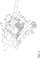
- FIG. 2 is a side view of the vehicle body frame 2 and the control unit assembly 20.
- the vehicle body frame 2 includes a first frame 17, a second frame 18, and a third frame 19.
- the first frame 17 is connected to the head pipe 11.
- the first frame 17 extends rearward from the head pipe 11.
- the second frame 18 is disposed below the first frame 17.
- the second frame 18 is connected to the head pipe 11.
- the second frame 18 extends rearward and downward from the head pipe 11.
- the third frame 19 is connected to the first and second frames 17 and 18.
- the control unit assembly 20 is attached to the vehicle body frame 2. When described in detail, the control unit assembly 20 is attached to the second and third frames 18 and 19. The control unit assembly 20 is disposed inside the side cover 29.
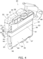
- FIGS. 3 and 4 are perspective views of the control unit assembly 20.
- FIG. 5 is a rear view of the control unit assembly 20. As shown in FIGS. 3 to 5 , the control unit assembly 20 includes a first control unit 21, a second control unit 22, and a holder 23.
- the first control unit 21 is an ECU (Engine Control Unit).
- the first control unit 21 electrically controls the engine 14.
- the first control unit 21 controls fuel injection and ignition timing in the engine 14.
- the first control unit 21 includes a first case 24 and a plurality of connectors 25.
- the first case 24 accommodates an electronic circuit (not shown in the drawings) for controlling the engine 14.
- the plural connectors 25 protrude from the first case 24. It should be noted that in the drawings, reference numeral 25 is assigned to only part of the plural connectors without being assigned to the other connectors.
- the second control unit 22 is an MCU (Motor Control Unit).
- the second control unit 22 electrically controls the motor 15.
- the second control unit 22 includes a second case 26 and a plurality of connectors 27.
- the second case 26 accommodates an electronic circuit (not shown in the drawings) for controlling the motor 15.
- the plural connectors 27 protrude from the second case 26. It should be noted that in the drawings, reference numeral 27 is assigned to only part of the plural connectors without being assigned to the other connectors.
- the holder 23 holds together the first and second control units 21 and 22.
- the holder 23 is made of resin.
- the holder 23 is provided as an integrated component.
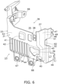
- FIGS. 6 and 7 are perspective views of the holder 23.
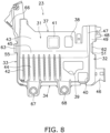
- FIG. 8 is a front view of the holder 23.
- FIG. 9 is a rear view of the holder 23.
- the holder 23 includes a first sidewall 31, a second sidewall 32, a third sidewall 33, a bottom surface 34, an accommodation space 35, a first opening 36, and a second opening 37.
- a direction facing a side on which the bottom surface 34 is located in the holder 23 is defined as “downward”, whereas a direction opposite thereto is defined as “upward”.
- a direction facing a side on which the first sidewall 31 is located in the holder 23 is defined as "forward”, whereas a direction opposite thereto is defined as “rearward”.
- a direction facing a side on which the second sidewall 32 is located in the holder 23 is defined as "leftward”, whereas a direction opposite thereto is defined as "rightward”.
- the accommodation space 35 is enclosed by the first sidewall 31, the second sidewall 32, the third sidewall 33, and the bottom surface 34.
- the first and second control units 21 and 22 are disposed in the accommodation space 35.
- the first and second control units 21 and 22 are disposed together, in common, in the accommodation space 35 without being partitioned off.
- the first opening 36 communicates with the accommodation space 35.
- the first opening 36 is opened rearward in the holder 23.
- the rear surface of the holder 23 is entirely opened as the first opening 36.
- the second opening 37 communicates with the accommodation space 35.
- the second opening 37 is opened upward in the holder 23.
- the top surface of the holder 23 is entirely opened as the second opening 37.
- the first sidewall 31 is located on the opposite side of the first opening 36 in the holder 23.
- the first sidewall 31 is disposed in opposition to the first opening 36.
- the first sidewall 31 is greater in area than each of the second sidewall 32, the third sidewall 33, and the bottom surface 34.
- the first sidewall 31 includes holes 38 to 40.
- the first sidewall 31 includes a protrusion 41.
- the protrusion 41 protrudes outward from the first sidewall 31 of the holder 23.
- the protrusion 41 is shaped to be recessed on the inner surface of the first sidewall 31.
- the first sidewall 31 includes a plurality of ribs 42.
- the plural ribs 42 protrude from the outer surface of the first sidewall 31.
- Each of the plural ribs 42 extends in the up-and-down direction of the holder 23. It should be noted that in the drawings, reference numeral 42 is assigned to only part of the plural ribs without being assigned to the other ribs.
- the first sidewall 31 includes an upper surface portion 43, a lower surface portion 44, and a front step portion 45.
- the lower surface portion 44 is disposed below the upper surface portion 43.
- the lower surface portion 44 is disposed further on a rear side than the upper surface portion 43.
- the front step portion 45 is disposed between the upper surface portion 43 and the lower surface portion 44.
- the front step portion 45 extends forward from the lower surface portion 44 toward the upper surface portion 43.
- the front step portion 45 extends in the right-and-left direction.
- the hole 38 is disposed in the upper surface portion 43.
- the holes 39 and 40 are disposed in the lower surface portion 44.
- the protrusion 41 is disposed on the upper surface portion 43.
- the plural ribs 42 are disposed on the lower surface portion 44.
- the plural ribs 42 extend downward from the front step portion 45.
- the second sidewall 32 extends rearward from the first sidewall 31.
- the second sidewall 32 extends from the first sidewall 31 toward the first opening 36.
- the second sidewall 32 extends upward from the bottom surface 34.
- the second sidewall 32 extends from the bottom surface 34 toward the second opening 37.
- a cable guide 46 is connected to the second sidewall 32.
- the cable guide 46 guides cables (not shown in the drawings) connected to the connectors 25 or the connectors 27.
- the second sidewall 32 includes a first front portion 47, a first rear portion 48, and a first step portion 49.
- the first front portion 47 is connected to the first sidewall 31.
- the first rear portion 48 is disposed behind the first front portion 47.
- the first rear portion 48 is disposed laterally outward of the first front portion 47.
- the first step portion 49 is disposed between the first front portion 47 and the first rear portion 48.
- the first step portion 49 is disposed to be directed to the first opening 36.
- the first step portion 49 extends laterally outward from the first front portion 47 toward the first rear portion 48.
- the first step portion 49 extends in the up-and-down direction.
- the second sidewall 32 includes a first cutout 51.
- the first cutout 51 extends forward from the rear edge of the second sidewall 32.
- the first control unit 21 is exposed to the outside of the holder 23 through the first cutout 51.
- the third sidewall 33 is disposed on the opposite side of the second sidewall 32.
- the third sidewall 33 extends rearward from the first sidewall 31.
- the third sidewall 33 extends from the first sidewall 31 toward the first opening 36.
- the third sidewall 33 extends upward from the bottom surface 34.
- the third sidewall 33 extends from the bottom surface 34 toward the second opening 37.
- the third sidewall 33 includes a second front portion 52, a second rear portion 53, and a second step portion 54.
- the second front portion 52 is connected to the first sidewall 31.
- the second rear portion 53 is disposed behind the second front portion 52.
- the second rear portion 53 is disposed laterally outward of the second front portion 52.
- the second step portion 54 is disposed between the second front portion 52 and the second rear portion 53.
- the second step portion 54 is disposed to be directed to the first opening 36.
- the second step portion 54 extends laterally outward from the second front portion 52 toward the second rear portion 53.
- the second step portion 54 extends in the up-and-down direction.
- the third sidewall 33 includes a second cutout 55.
- the second cutout 55 extends forward from the rear edge of the third sidewall 33.
- the first control unit 21 is exposed to the outside of the holder 23 through the second cutout 55.
- the bottom surface 34 extends rearward from the first sidewall 31. In the holder 23, the bottom surface 34 extends in the right-and-left direction. As shown in FIG. 7 , the bottom surface 34 includes a third front portion 56, a third rear portion 57, and a third step portion 58.
- the third front portion 56 is connected to the first sidewall 31.
- the third rear portion 57 is disposed behind the third front portion 56.
- the third rear portion 57 is disposed further on a lower side than the third front portion 56.
- the third step portion 58 is disposed between the third front portion 56 and the third rear portion 57.
- the third step portion 58 extends downward from the third front portion 56 toward the third rear portion 57.
- the third step portion 58 extends in the right-and-left direction.
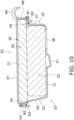
- FIG. 10 is a cross-sectional view of FIG. 8 taken along line X-X.
- the first control unit 21 is disposed to close the first opening 36.
- the second control unit 22 is disposed between the first sidewall 31 and the first control unit 21.
- the first and second control units 21 and 22 are disposed to be stacked back and forth in the accommodation space 35.
- the first and second control units 21 and 22 do not interpose the holder 23 therebetween.
- the first and second control units 21 and 22 are in contact with each other.
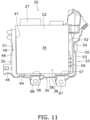
- FIG. 11 is a rear view of the control unit assembly 20, from which the first control unit 21 is omitted.
- the second control unit 22 is disposed between the first front portion 47 of the second sidewall 32 and the second front portion 52 of the third sidewall 33.
- the second control unit 22 is disposed on the third front portion 56 of the bottom surface 34.
- the third sidewall 33 includes a plurality of positioning ribs 59 protruding from the inner surface of the second front portion 52.
- the second control unit 22 is set in place by the plural positioning ribs 59 in the interior of the holder 23. It should be noted that in the drawings, reference numeral 59 is assigned to only part of the plural positioning ribs without being assigned to the other positioning ribs.
- the first step portion 49 is disposed to be flush with the second control unit 22.
- the second step portion 54 is disposed to be flush with the second control unit 22.
- the first opening 36 is greater in size than the first control unit 21.
- the first control unit 21 is greater in size than the second control unit 22.
- the first control unit 21 is greater in size than the second control unit 22 in the right-and-left direction.
- the first control unit 21 is greater in size than the second control unit 22 in the up-and-down direction.
- the first control unit 21 is disposed between the first rear portion 48 of the second sidewall 32 and the second rear portion 53 of the third sidewall 33.
- the first control unit 21 is disposed on the third rear portion 57 of the bottom surface 34.
- the first control unit 21 is engaged to the first step portion 49 of the second sidewall 32.
- the first control unit 21 is engaged to the second step portion 54 of the third sidewall 33.
- the first control unit 21 is engaged to the third step portion 58 of the bottom surface 34.
- the first control unit 21 is fixed to the holder 23. Accordingly, the first control unit 21 functions as a lid for the first opening 36.
- the control unit assembly 20 includes a fixation member 61 made of an elastic body so as to fix the first control unit 21 to the holder 23.
- the fixation member 61 is disposed to be stretched between the second and third sidewalls 32 and 33.
- the fixation member 61 is locked to the second and third sidewalls 32 and 33 and is thereby fixed to the holder 23.
- the fixation member 61 is, for instance, a band made of an elastic body.
- the second sidewall 32 includes a first lock pawl 62.
- the first lock pawl 62 is disposed in front of the first cutout 51.
- the third sidewall 33 includes a second lock pawl 63.
- the second lock pawl 63 is disposed in front of the second cutout 55.
- the fixation member 61 is engaged to the first and second lock pawls 62 and 63.
- the fixation member 61 is provided with hooks 81 and 82 attached to both ends thereof, respectively.
- the hooks 81 and 82 are engaged to the first and second lock pawls 62 and 63, respectively.
- the fixation member 61 is in contact with the first control unit 21, while penetrating the first and second cutouts 51 and 55.
- the first control unit 21 is pressed toward the first to third step portions 49, 54, and 58 by the elastic force of the fixation member 61; hence, the first control unit 21 is in contact with the first to third step portions 49, 54, and 58. Accordingly, the first control unit 21 is fixed to the holder 23.
- the bottom surface 34 includes a lock pawl 64. The lock pawl 64 is locked to the first control unit 21, whereby a bottom part of the first control unit 21 is restricted from moving rearward.
- the control unit assembly 20 is disposed laterally outside the first frame 17.
- the control unit assembly 20 is disposed such that the first sidewall 31 is directed to the laterally outer side of the straddled vehicle 1.
- the control unit assembly 20 is disposed such that the first opening 36 is directed to the laterally inner side of the straddled vehicle 1.
- the control unit assembly 20 is fixed to the second and third frames 18 and 19.
- the holder 23 includes a first fixed portion 66, a second fixed portion 67, and a third fixed portion 68.
- the first fixed portion 66 is connected to the third sidewall 33.
- the first fixed portion 66 is attached to the second frame 18.
- the first fixed portion 66 is fixed to the second frame 18 by a bolt 17.
- the second fixed portion 67 is connected to the bottom surface 34.
- the second fixed portion 67 is fixed to the third frame 19.
- the second fixed portion 67 is fixed to the third frame 19 by a bolt 72.
- the third fixed portion 68 is connected to the bottom surface 34 in similar manner to the second fixed portion 67.
- the third fixed portion 68 is attached to the third frame 19.
- the third fixed portion 68 is fixed to the third frame 19 by a bolt 73.
- the first and second control units 21 and 22 are disposed in the accommodation space 35 of the holder 23. Then, the first opening 36 of the holder 23 is closed by the first control unit 21. Because of this, the first control unit 21 functions as a lid for the first opening 36, whereby the second control unit 22 can be inhibited from being detached and dropping from the holder 23. Accordingly, the first and second control units 21 and 22 are stably held by the holder 23. Besides, the first control unit 21 functions as the lid for the first opening 36, whereby the holder 23 is not provided with a lid. Accordingly, the holder 23 is made compact in size.
- the first control unit 21 is in contact with the first and second step portions 49 and 54, while being fixed to the holder 23 by the fixation member 61. Because of this, as shown in FIG. 12 , even when the second control unit 22 is omitted, only the first control unit 21 can be held in the holder 23 by the fixation member 61. Accordingly, the holder 23 is made compatible with a straddled vehicle having a specification with installation of both the first and second control units 21 and 22 and a straddled vehicle having a specification without installation of the second control unit 22.
- the straddled vehicle 1 is not limited to a type of vehicle in the preferred embodiment described above, and alternatively, may be another type of vehicle such as an off-road motorcycle, a scooter, or a moped.
- the positional arrangement of the control unit assembly 20 in the straddled vehicle 1 is not limited to that in the preferred embodiment described above and may be changed.
- the control unit assembly 20 may be disposed behind the front cover 28.
- the control unit assembly 20 may be disposed below the seat 6.
- the control unit assembly 20 may be disposed further on a rear side than the seat 6.
- the first control unit 21 is not limited to the ECU and may be another type of control unit.
- the second control unit 22 is not limited to the MCU and may be another type of control unit.
- the second control unit 22 is not limited to the type of control unit for controlling the starter motor; alternatively, the second control unit 22 may be a type of control unit for controlling another type of motor such as a motor for assisting the drive force of the engine 14, a motor for controlling the electronic throttle of the engine 14, or a motor for moving the screen 30.
- first control unit 21 and that of the second control unit 22 are not limited to those in the preferred embodiment described above and may be changed.
- the first and second control units 21 and 22 may be equal in size to each other.
- the first control unit 21 may be lesser in size than the second control unit 22.
- the structure of the holder 23 is not limited to that in the preferred embodiment described above and may be changed.
- the ribs or the holes may be omitted.
- the fixation portions 66 to 68 for fixing the holder 23 to the vehicle body frame 2 may be changed in position or number.
- the means for fixing the first control unit 21 to the holder 23 is not limited to the fixation member 61, and alternatively, may be another fixation means such as screws or snap-fits.
- an intermediate member 69 provided as a member separated from the holder 23, may be disposed between the first and second control units 21 and 22.
- the intermediate member 69 may be a thermal insulator material.
- the intermediate member 69 may be a buffer material.
Landscapes
- Engineering & Computer Science (AREA)
- Mechanical Engineering (AREA)
- Automatic Cycles, And Cycles In General (AREA)
Abstract
Description
- The present invention relates to a straddled vehicle.
- There is a type of straddled vehicle including a holder for accommodating a plurality of control units. For example,
Japan Laid-open Patent Application Publication No. 2020-147117 - In the structure for attaching electric components described above, the first and second control devices are stably held by the upper case, while being inhibited from dropping out of the upper case. However, the upper case is undesirably increased in size by the first and second lock plates.
- As described above, when the holder for accommodating the plural control units is increased in size, the straddled vehicle is undesirably increased in weight or manufacturing cost. Aside from this, the straddled vehicle is undesirably limited in layout of the plural control units by increase in size of the holder. It is an object of the present invention to achieve the following in a straddled vehicle: stably holding a plurality of control units by a common holder and making the holder compact in size.
- A straddled vehicle according to an aspect of the present invention includes a first control unit, a second control unit, and a holder. The holder holds together the first and second control units. The holder includes an accommodation space and a first opening. The first and second control units are disposed in the accommodation space. The first opening communicates with the accommodation space and is opened to one lateral side of the holder. The first control unit is disposed to close the first opening.
- In the straddled vehicle according to the present aspect, the first and second control units are disposed in the accommodation space of the holder. Then, the first opening of the holder is closed by the first control unit. Because of this, the first control unit functions as a lid for the first opening, whereby the second control unit can be inhibited from being detached and dropping from the holder. Accordingly, the first and second control units are stably held by the holder. Besides, the first control unit functions as the lid for the first opening, whereby the holder is not provided with a lid. Accordingly, the holder is made compact in size.
- The holder may include a first sidewall located on an opposite side of the first opening in the holder. The second control unit may be disposed between the first sidewall and the first control unit. In this case, the second control unit can be inhibited from being detached and dropping from the holder by the first sidewall and the first control unit.
- The holder may further include a second sidewall extending from the first sidewall toward the first opening. In this case, the first and second control units can be inhibited from being detached and dropping from the case by the second sidewall.
- An inner surface of the second sidewall may include a first step portion, disposed to be directed to the first opening. The first control unit may be locked to the first step portion. In this case, the first control unit is set in place by the first step portion. Besides, the first control unit is locked to the first step portion, whereby the first control unit is stably held by the holder even without installation of the second control unit. Because of this, the holder can be used even in a straddled vehicle having a specification without installation of the second control unit.
- The first step portion may be disposed to be flush with the second control unit. In this case, the second control unit is tightly disposed between the first control unit and the holder.
- The holder may further include a third sidewall. The third sidewall may be disposed on an opposite side of the second sidewall. The third sidewall may extend from the first sidewall toward the first opening. In this case, the first and second control units can be inhibited from being detached and dropping from the holder by the third sidewall.
- An inner surface of the third sidewall may include a second step portion, disposed to be directed to the first opening. The first control unit may be locked to the second step portion. In this case, the first control unit is locked to the second step portion, whereby the first control unit is stably held by the holder even without installation of the second control unit. Because of this, the holder can be used even in the straddled vehicle having the specification without installation of the second control unit.
- The second step portion may be disposed to be flush with the second control unit. In this case, the second control unit is tightly disposed between the first control unit and the holder.
- The holder may further include a second opening opened to an upper side of the holder. In this case, access to the first and second control units is made easy from above the holder.
- The first control unit may be greater in size than the second control unit in a view from the first opening. In this case, the second control unit can be further effectively inhibited from being detached and dropping from the holder.
- The first control unit may be in contact with the second control unit. In this case, the first and second control units are compactly disposed.
- The straddled vehicle may further include an intermediate member. The intermediate member may be disposed between the first and second control units. The intermediate member may be provided as a member separated from the holder. In this case, a thermal insulator material, a buffer material, or so forth can be disposed, as the intermediate member, between the first and second control units.
- The holder may be made of resin. In this case, the holder is likely to bend; hence, attaching the first and second control units to the holder is made easy.
- The first control unit may be fixed to the holder. In this case, the first control unit can be inhibited from being detached and dropping from the holder.
- The straddled vehicle may further include a fixation member that is made of an elastic body and fixes the first control unit to the holder. In this case, fixing the first control unit to the holder is made easy.
-
-
FIG. 1 is a side view of a straddled vehicle according to a preferred embodiment. -
FIG. 2 is a side view of a vehicle body frame and a control unit assembly. -
FIG. 3 is a perspective view of the control unit assembly. -
FIG. 4 is a perspective view of the control unit assembly. -
FIG. 5 is a rear view of the control unit assembly. -
FIG. 6 is a perspective view of a holder. -
FIG. 7 is a perspective view of the holder. -
FIG. 8 is a front view of the holder. -
FIG. 9 is a rear view of the holder. -
FIG. 10 is a cross-sectional view ofFIG. 8 taken along line X-X. -
FIG. 11 is a rear view of the control unit assembly from which a first control unit is omitted. -
FIG. 12 is a cross-sectional view of the control unit assembly from which a second control unit is omitted. -
FIG. 13 is a cross-sectional view of a control unit assembly according to a modification. - A preferred embodiment will be hereinafter explained with reference to drawings.
FIG. 1 is a side view of a straddled vehicle 1 according to the preferred embodiment. The straddled vehicle 1 according to the present preferred embodiment is a motorcycle. The straddled vehicle 1 includes avehicle body frame 2, asteering device 3, afront wheel 4, afuel tank 5, aseat 6, apower unit 7, arear wheel 8, and avehicle body cover 9. - The
vehicle body frame 2 includes ahead pipe 11. Thehead pipe 11 supports thesteering device 3 such that thesteering device 3 is made turnable right and left. Thesteering device 3 includes afront fork 12 and ahandle member 13. Thefront fork 12 supports thefront wheel 4 such that thefront wheel 4 is made rotatable. Thehandle member 13 is connected to an upper portion of thefront fork 12. - The
fuel tank 5 is disposed behind thehead pipe 11. Theseat 6 is disposed behind thefuel tank 5. Thepower unit 7 is disposed below theseat 6. Thepower unit 7 includes anengine 14 and amotor 15. Themotor 15 is a starter motor for starting theengine 14. Themotor 15 may be an ISG (Integrated Starter Generator) functioning as both a starter and a generator. Therear wheel 8 is supported by thevehicle body frame 2 or thepower unit 7 through aswing arm 16. Therear wheel 8 is supported by theswing arm 16 so as to be rotatable. - The
vehicle body cover 9 covers part of thevehicle body frame 2. Thevehicle body cover 9 includes afront cover 28 and aside cover 29. Thefront cover 28 is disposed in front of thehead pipe 11. Ascreen 30 is attached to thefront cover 28. The side cover 29 covers thevehicle body frame 2 from lateral sides. - The straddled vehicle 1 includes a
control unit assembly 20.FIG. 2 is a side view of thevehicle body frame 2 and thecontrol unit assembly 20. As shown inFIG. 2 , thevehicle body frame 2 includes afirst frame 17, asecond frame 18, and athird frame 19. Thefirst frame 17 is connected to thehead pipe 11. Thefirst frame 17 extends rearward from thehead pipe 11. Thesecond frame 18 is disposed below thefirst frame 17. Thesecond frame 18 is connected to thehead pipe 11. Thesecond frame 18 extends rearward and downward from thehead pipe 11. Thethird frame 19 is connected to the first andsecond frames - The
control unit assembly 20 is attached to thevehicle body frame 2. When described in detail, thecontrol unit assembly 20 is attached to the second andthird frames control unit assembly 20 is disposed inside theside cover 29.FIGS. 3 and4 are perspective views of thecontrol unit assembly 20.FIG. 5 is a rear view of thecontrol unit assembly 20. As shown inFIGS. 3 to 5 , thecontrol unit assembly 20 includes afirst control unit 21, asecond control unit 22, and aholder 23. - The
first control unit 21 is an ECU (Engine Control Unit). Thefirst control unit 21 electrically controls theengine 14. For example, thefirst control unit 21 controls fuel injection and ignition timing in theengine 14. As shown inFIGS. 3 and4 , thefirst control unit 21 includes afirst case 24 and a plurality ofconnectors 25. Thefirst case 24 accommodates an electronic circuit (not shown in the drawings) for controlling theengine 14. Theplural connectors 25 protrude from thefirst case 24. It should be noted that in the drawings,reference numeral 25 is assigned to only part of the plural connectors without being assigned to the other connectors. - The
second control unit 22 is an MCU (Motor Control Unit). Thesecond control unit 22 electrically controls themotor 15. Thesecond control unit 22 includes asecond case 26 and a plurality ofconnectors 27. Thesecond case 26 accommodates an electronic circuit (not shown in the drawings) for controlling themotor 15. Theplural connectors 27 protrude from thesecond case 26. It should be noted that in the drawings,reference numeral 27 is assigned to only part of the plural connectors without being assigned to the other connectors. - The
holder 23 holds together the first andsecond control units holder 23 is made of resin. For example, theholder 23 is provided as an integrated component.FIGS. 6 and7 are perspective views of theholder 23.FIG. 8 is a front view of theholder 23.FIG. 9 is a rear view of theholder 23. - As shown in
FIGS. 6 to 9 , theholder 23 includes afirst sidewall 31, asecond sidewall 32, athird sidewall 33, abottom surface 34, anaccommodation space 35, afirst opening 36, and asecond opening 37. It should be noted that in the following explanation, a direction facing a side on which thebottom surface 34 is located in theholder 23 is defined as "downward", whereas a direction opposite thereto is defined as "upward". A direction facing a side on which thefirst sidewall 31 is located in theholder 23 is defined as "forward", whereas a direction opposite thereto is defined as "rearward". A direction facing a side on which thesecond sidewall 32 is located in theholder 23 is defined as "leftward", whereas a direction opposite thereto is defined as "rightward". - The
accommodation space 35 is enclosed by thefirst sidewall 31, thesecond sidewall 32, thethird sidewall 33, and thebottom surface 34. The first andsecond control units accommodation space 35. The first andsecond control units accommodation space 35 without being partitioned off. - The
first opening 36 communicates with theaccommodation space 35. Thefirst opening 36 is opened rearward in theholder 23. The rear surface of theholder 23 is entirely opened as thefirst opening 36. Thesecond opening 37 communicates with theaccommodation space 35. Thesecond opening 37 is opened upward in theholder 23. The top surface of theholder 23 is entirely opened as thesecond opening 37. - The
first sidewall 31 is located on the opposite side of thefirst opening 36 in theholder 23. Thefirst sidewall 31 is disposed in opposition to thefirst opening 36. Thefirst sidewall 31 is greater in area than each of thesecond sidewall 32, thethird sidewall 33, and thebottom surface 34. Thefirst sidewall 31 includesholes 38 to 40. Thefirst sidewall 31 includes aprotrusion 41. Theprotrusion 41 protrudes outward from thefirst sidewall 31 of theholder 23. Theprotrusion 41 is shaped to be recessed on the inner surface of thefirst sidewall 31. Thefirst sidewall 31 includes a plurality ofribs 42. Theplural ribs 42 protrude from the outer surface of thefirst sidewall 31. Each of theplural ribs 42 extends in the up-and-down direction of theholder 23. It should be noted that in the drawings,reference numeral 42 is assigned to only part of the plural ribs without being assigned to the other ribs. - The
first sidewall 31 includes anupper surface portion 43, alower surface portion 44, and afront step portion 45. Thelower surface portion 44 is disposed below theupper surface portion 43. Thelower surface portion 44 is disposed further on a rear side than theupper surface portion 43. As shown inFIG. 4 , thefront step portion 45 is disposed between theupper surface portion 43 and thelower surface portion 44. Thefront step portion 45 extends forward from thelower surface portion 44 toward theupper surface portion 43. In thefirst sidewall 31, thefront step portion 45 extends in the right-and-left direction. Thehole 38 is disposed in theupper surface portion 43. Theholes lower surface portion 44. Theprotrusion 41 is disposed on theupper surface portion 43. Theplural ribs 42 are disposed on thelower surface portion 44. Theplural ribs 42 extend downward from thefront step portion 45. - The
second sidewall 32 extends rearward from thefirst sidewall 31. Thesecond sidewall 32 extends from thefirst sidewall 31 toward thefirst opening 36. Thesecond sidewall 32 extends upward from thebottom surface 34. Thesecond sidewall 32 extends from thebottom surface 34 toward thesecond opening 37. Acable guide 46 is connected to thesecond sidewall 32. Thecable guide 46 guides cables (not shown in the drawings) connected to theconnectors 25 or theconnectors 27. Thesecond sidewall 32 includes afirst front portion 47, a firstrear portion 48, and afirst step portion 49. - The
first front portion 47 is connected to thefirst sidewall 31. The firstrear portion 48 is disposed behind thefirst front portion 47. The firstrear portion 48 is disposed laterally outward of thefirst front portion 47. Thefirst step portion 49 is disposed between thefirst front portion 47 and the firstrear portion 48. Thefirst step portion 49 is disposed to be directed to thefirst opening 36. Thefirst step portion 49 extends laterally outward from thefirst front portion 47 toward the firstrear portion 48. In thesecond sidewall 32, thefirst step portion 49 extends in the up-and-down direction. Thesecond sidewall 32 includes afirst cutout 51. Thefirst cutout 51 extends forward from the rear edge of thesecond sidewall 32. Thefirst control unit 21 is exposed to the outside of theholder 23 through thefirst cutout 51. - The
third sidewall 33 is disposed on the opposite side of thesecond sidewall 32. Thethird sidewall 33 extends rearward from thefirst sidewall 31. Thethird sidewall 33 extends from thefirst sidewall 31 toward thefirst opening 36. Thethird sidewall 33 extends upward from thebottom surface 34. Thethird sidewall 33 extends from thebottom surface 34 toward thesecond opening 37. As shown inFIGS. 7 and9 , thethird sidewall 33 includes asecond front portion 52, a secondrear portion 53, and asecond step portion 54. - The
second front portion 52 is connected to thefirst sidewall 31. The secondrear portion 53 is disposed behind thesecond front portion 52. The secondrear portion 53 is disposed laterally outward of thesecond front portion 52. Thesecond step portion 54 is disposed between thesecond front portion 52 and the secondrear portion 53. Thesecond step portion 54 is disposed to be directed to thefirst opening 36. Thesecond step portion 54 extends laterally outward from thesecond front portion 52 toward the secondrear portion 53. In thethird sidewall 33, thesecond step portion 54 extends in the up-and-down direction. Thethird sidewall 33 includes asecond cutout 55. Thesecond cutout 55 extends forward from the rear edge of thethird sidewall 33. Thefirst control unit 21 is exposed to the outside of theholder 23 through thesecond cutout 55. - The
bottom surface 34 extends rearward from thefirst sidewall 31. In theholder 23, thebottom surface 34 extends in the right-and-left direction. As shown inFIG. 7 , thebottom surface 34 includes a thirdfront portion 56, a thirdrear portion 57, and athird step portion 58. The thirdfront portion 56 is connected to thefirst sidewall 31. The thirdrear portion 57 is disposed behind the thirdfront portion 56. The thirdrear portion 57 is disposed further on a lower side than the thirdfront portion 56. Thethird step portion 58 is disposed between the thirdfront portion 56 and the thirdrear portion 57. Thethird step portion 58 extends downward from the thirdfront portion 56 toward the thirdrear portion 57. In thebottom surface 34, thethird step portion 58 extends in the right-and-left direction. -
FIG. 10 is a cross-sectional view ofFIG. 8 taken along line X-X. As shown inFIGS. 3 ,4 , and10 , thefirst control unit 21 is disposed to close thefirst opening 36. Thesecond control unit 22 is disposed between thefirst sidewall 31 and thefirst control unit 21. The first andsecond control units accommodation space 35. The first andsecond control units holder 23 therebetween. The first andsecond control units -
FIG. 11 is a rear view of thecontrol unit assembly 20, from which thefirst control unit 21 is omitted. As shown inFIG. 11 , thesecond control unit 22 is disposed between thefirst front portion 47 of thesecond sidewall 32 and thesecond front portion 52 of thethird sidewall 33. Thesecond control unit 22 is disposed on the thirdfront portion 56 of thebottom surface 34. Thethird sidewall 33 includes a plurality of positioningribs 59 protruding from the inner surface of thesecond front portion 52. Thesecond control unit 22 is set in place by theplural positioning ribs 59 in the interior of theholder 23. It should be noted that in the drawings,reference numeral 59 is assigned to only part of the plural positioning ribs without being assigned to the other positioning ribs. As shown inFIG. 10 , thefirst step portion 49 is disposed to be flush with thesecond control unit 22. Thesecond step portion 54 is disposed to be flush with thesecond control unit 22. - As shown in
FIG. 5 , in the rear view of theholder 23, thefirst opening 36 is greater in size than thefirst control unit 21. In the rear view of theholder 23, thefirst control unit 21 is greater in size than thesecond control unit 22. When described in detail, in the rear view of theholder 23, thefirst control unit 21 is greater in size than thesecond control unit 22 in the right-and-left direction. In the rear view of theholder 23, thefirst control unit 21 is greater in size than thesecond control unit 22 in the up-and-down direction. - The
first control unit 21 is disposed between the firstrear portion 48 of thesecond sidewall 32 and the secondrear portion 53 of thethird sidewall 33. Thefirst control unit 21 is disposed on the thirdrear portion 57 of thebottom surface 34. Thefirst control unit 21 is engaged to thefirst step portion 49 of thesecond sidewall 32. Thefirst control unit 21 is engaged to thesecond step portion 54 of thethird sidewall 33. Thefirst control unit 21 is engaged to thethird step portion 58 of thebottom surface 34. - The
first control unit 21 is fixed to theholder 23. Accordingly, thefirst control unit 21 functions as a lid for thefirst opening 36. When described in detail, thecontrol unit assembly 20 includes afixation member 61 made of an elastic body so as to fix thefirst control unit 21 to theholder 23. Thefixation member 61 is disposed to be stretched between the second andthird sidewalls fixation member 61 is locked to the second andthird sidewalls holder 23. Thefixation member 61 is, for instance, a band made of an elastic body. - As shown in
FIG. 8 , thesecond sidewall 32 includes afirst lock pawl 62. Thefirst lock pawl 62 is disposed in front of thefirst cutout 51. Thethird sidewall 33 includes asecond lock pawl 63. Thesecond lock pawl 63 is disposed in front of thesecond cutout 55. Thefixation member 61 is engaged to the first andsecond lock pawls FIG. 10 , thefixation member 61 is provided withhooks hooks second lock pawls fixation member 61 is in contact with thefirst control unit 21, while penetrating the first andsecond cutouts - The
first control unit 21 is pressed toward the first tothird step portions fixation member 61; hence, thefirst control unit 21 is in contact with the first tothird step portions first control unit 21 is fixed to theholder 23. Besides, as shown inFIGS. 4 and7 , thebottom surface 34 includes alock pawl 64. Thelock pawl 64 is locked to thefirst control unit 21, whereby a bottom part of thefirst control unit 21 is restricted from moving rearward. - As shown in
FIG. 2 , thecontrol unit assembly 20 is disposed laterally outside thefirst frame 17. Thecontrol unit assembly 20 is disposed such that thefirst sidewall 31 is directed to the laterally outer side of the straddled vehicle 1. In other words, thecontrol unit assembly 20 is disposed such that thefirst opening 36 is directed to the laterally inner side of the straddled vehicle 1. Thecontrol unit assembly 20 is fixed to the second andthird frames - As shown in
FIG. 5 , theholder 23 includes a first fixedportion 66, a second fixedportion 67, and a third fixedportion 68. The first fixedportion 66 is connected to thethird sidewall 33. As shown inFIG. 2 , the first fixedportion 66 is attached to thesecond frame 18. The first fixedportion 66 is fixed to thesecond frame 18 by abolt 17. The second fixedportion 67 is connected to thebottom surface 34. As shown inFIG. 2 , the second fixedportion 67 is fixed to thethird frame 19. The second fixedportion 67 is fixed to thethird frame 19 by abolt 72. The thirdfixed portion 68 is connected to thebottom surface 34 in similar manner to the second fixedportion 67. As shown inFIG. 2 , the third fixedportion 68 is attached to thethird frame 19. The thirdfixed portion 68 is fixed to thethird frame 19 by abolt 73. - In the straddled vehicle 1 according to the present preferred embodiment explained above, the first and
second control units accommodation space 35 of theholder 23. Then, thefirst opening 36 of theholder 23 is closed by thefirst control unit 21. Because of this, thefirst control unit 21 functions as a lid for thefirst opening 36, whereby thesecond control unit 22 can be inhibited from being detached and dropping from theholder 23. Accordingly, the first andsecond control units holder 23. Besides, thefirst control unit 21 functions as the lid for thefirst opening 36, whereby theholder 23 is not provided with a lid. Accordingly, theholder 23 is made compact in size. - The
first control unit 21 is in contact with the first andsecond step portions holder 23 by thefixation member 61. Because of this, as shown inFIG. 12 , even when thesecond control unit 22 is omitted, only thefirst control unit 21 can be held in theholder 23 by thefixation member 61. Accordingly, theholder 23 is made compatible with a straddled vehicle having a specification with installation of both the first andsecond control units second control unit 22. - One preferred embodiment of the present invention has been explained above. However, the present invention is not limited to the preferred embodiment described above, and a variety of changes can be made without departing from the gist of the present invention.
- The straddled vehicle 1 is not limited to a type of vehicle in the preferred embodiment described above, and alternatively, may be another type of vehicle such as an off-road motorcycle, a scooter, or a moped. The positional arrangement of the
control unit assembly 20 in the straddled vehicle 1 is not limited to that in the preferred embodiment described above and may be changed. For example, thecontrol unit assembly 20 may be disposed behind thefront cover 28. Thecontrol unit assembly 20 may be disposed below theseat 6. Alternatively, thecontrol unit assembly 20 may be disposed further on a rear side than theseat 6. - The
first control unit 21 is not limited to the ECU and may be another type of control unit. Thesecond control unit 22 is not limited to the MCU and may be another type of control unit. Thesecond control unit 22 is not limited to the type of control unit for controlling the starter motor; alternatively, thesecond control unit 22 may be a type of control unit for controlling another type of motor such as a motor for assisting the drive force of theengine 14, a motor for controlling the electronic throttle of theengine 14, or a motor for moving thescreen 30. - The shape of the
first control unit 21 and that of thesecond control unit 22 are not limited to those in the preferred embodiment described above and may be changed. For example, the first andsecond control units first control unit 21 may be lesser in size than thesecond control unit 22. - The structure of the
holder 23 is not limited to that in the preferred embodiment described above and may be changed. For example, the ribs or the holes may be omitted. Thefixation portions 66 to 68 for fixing theholder 23 to thevehicle body frame 2 may be changed in position or number. The means for fixing thefirst control unit 21 to theholder 23 is not limited to thefixation member 61, and alternatively, may be another fixation means such as screws or snap-fits. - In the preferred embodiment described above, nothing is disposed between the first and
second control units FIG. 13 , anintermediate member 69, provided as a member separated from theholder 23, may be disposed between the first andsecond control units intermediate member 69 may be a thermal insulator material. Alternatively, theintermediate member 69 may be a buffer material. -
- 21: First control unit
- 22: Second control unit
- 23: Holder
- 31: First sidewall
- 32: Second sidewall
- 33: Third sidewall
- 35: Accommodation space
- 36: First opening
- 37: Second opening
- 49: First step portion
- 54: Second step portion
- 61: Fixation member
- 69: Intermediate member
Claims (15)
- A straddled vehicle (1) comprising:a first control unit (21);a second control unit (22); anda holder (23) holding together the first control unit (21) and the second control unit (22), wherein the holder (23) includesan accommodation space (35) in which the first control unit (21) and the second control unit (22) are disposed, anda first opening (36) communicating with the accommodation space (35), the first opening (36) opened to one lateral side of the holder (23), andthe first control unit (21) is disposed to close the first opening (36).
- The straddled vehicle according to claim 1, whereinthe holder (23) includes a first sidewall (31) located on an opposite side of the first opening (36) in the holder (23), andthe second control unit (22) is disposed between the first sidewall (31) and the first control unit (21).
- The straddled vehicle according to claim 2, wherein the holder (23) further includes a second sidewall (32) extending from the first sidewall (31) toward the first opening (36).
- The straddled vehicle according to claim 3, whereinan inner surface of the second sidewall (32) includes a first step portion (49) disposed to be directed to the first opening (36), andthe first control unit (21) is locked to the first step portion (49).
- The straddled vehicle according to claim 4, wherein the first step portion (49) is disposed to be flush with the second control unit (22).
- The straddled vehicle according to any one of claims 3 to 5, wherein the holder (23) further includes a third sidewall (33) disposed on an opposite side of the second sidewall (32) and extending from the first sidewall (31) toward the first opening (36).
- The straddled vehicle according to claim 6, whereinan inner surface of the third sidewall (31) includes a second step portion (54) disposed to be directed to the first opening (36), andthe first control unit (21) is locked to the second step portion (54).
- The straddled vehicle according to claim 7, wherein the second step portion (54) is disposed to be flush with the second control unit (22).
- The straddled vehicle according to any one of claims 1 to 8, wherein the holder (23)further includes a second opening (37) opened to an upper side of the holder (23).
- The straddled vehicle according to any one of claims 1 to 9, wherein the first control unit (21) is greater in size than the second control unit (22) in a view from the first opening (36).
- The straddled vehicle according to any one of claims 1 to 10, wherein the first control unit (21) is in contact with the second control unit (22).
- The straddled vehicle according to any one of claims 1 to 11, further comprising:
an intermediate member (69) disposed between the first and second control units (21, 22) and provided as a member separated from the holder (23). - The straddled vehicle according to any one of claims 1 to 12, wherein the holder (23) is made of resin.
- The straddled vehicle according to any one of claims 1 to 13, wherein the first control unit (21) is fixed to the holder (23).
- The straddled vehicle (1) according to any one of claims 1 to 14, further comprising:
a fixation member (61) made of an elastic body and fixing the first control unit (21) to the holder (23).
Applications Claiming Priority (1)
| Application Number | Priority Date | Filing Date | Title |
|---|---|---|---|
| JP2022160676A JP2024054461A (en) | 2022-10-05 | 2022-10-05 | Saddle-type vehicle |
Publications (2)
| Publication Number | Publication Date |
|---|---|
| EP4349699A1 true EP4349699A1 (en) | 2024-04-10 |
| EP4349699B1 EP4349699B1 (en) | 2025-11-19 |
Family
ID=85704932
Family Applications (1)
| Application Number | Title | Priority Date | Filing Date |
|---|---|---|---|
| EP23160402.6A Active EP4349699B1 (en) | 2022-10-05 | 2023-03-07 | Straddled vehicle |
Country Status (2)
| Country | Link |
|---|---|
| EP (1) | EP4349699B1 (en) |
| JP (1) | JP2024054461A (en) |
Citations (3)
| Publication number | Priority date | Publication date | Assignee | Title |
|---|---|---|---|---|
| JP2020147117A (en) | 2019-03-12 | 2020-09-17 | 本田技研工業株式会社 | Electrical component mounting structure for saddle-mounted vehicles |
| EP3925869A1 (en) * | 2020-06-19 | 2021-12-22 | Yamaha Hatsudoki Kabushiki Kaisha | Straddled vehicle communication and engine control units |
| JP2022062939A (en) * | 2020-10-09 | 2022-04-21 | スズキ株式会社 | Support structure of on-vehicle component |
-
2022
- 2022-10-05 JP JP2022160676A patent/JP2024054461A/en active Pending
-
2023
- 2023-03-07 EP EP23160402.6A patent/EP4349699B1/en active Active
Patent Citations (4)
| Publication number | Priority date | Publication date | Assignee | Title |
|---|---|---|---|---|
| JP2020147117A (en) | 2019-03-12 | 2020-09-17 | 本田技研工業株式会社 | Electrical component mounting structure for saddle-mounted vehicles |
| DE102020106588A1 (en) * | 2019-03-12 | 2020-09-17 | Honda Motor Co., Ltd. | FASTENING STRUCTURE OF AN ELECTRICAL COMPONENT FOR A SADDLE SEAT VEHICLE |
| EP3925869A1 (en) * | 2020-06-19 | 2021-12-22 | Yamaha Hatsudoki Kabushiki Kaisha | Straddled vehicle communication and engine control units |
| JP2022062939A (en) * | 2020-10-09 | 2022-04-21 | スズキ株式会社 | Support structure of on-vehicle component |
Also Published As
| Publication number | Publication date |
|---|---|
| JP2024054461A (en) | 2024-04-17 |
| EP4349699B1 (en) | 2025-11-19 |
Similar Documents
| Publication | Publication Date | Title |
|---|---|---|
| JP3491708B2 (en) | Battery storage device for electric bicycle | |
| EP3748711B1 (en) | Vehicle battery pack | |
| EP2759460B1 (en) | Personal digital assistance case of saddle-ride vehicle | |
| US10992007B2 (en) | Battery, battery case, and electric vehicle | |
| JP5112237B2 (en) | Motorcycle battery arrangement structure | |
| TWI712535B (en) | Straddled vehicle | |
| EP2447137B1 (en) | Mounting structure of antitheft device for saddle-type vehicle | |
| JP4095086B2 (en) | Saddle riding vehicle | |
| TW202200424A (en) | Straddled vehicle | |
| EP4349699B1 (en) | Straddled vehicle | |
| EP3604095B1 (en) | Battery support structure for saddle-type vehicle | |
| EP4279367A1 (en) | Straddle-type vehicle | |
| KR100297916B1 (en) | A coupler for a car battery | |
| CN111038624B (en) | Saddle-riding type vehicle | |
| JP2023046904A (en) | Saddle-riding type vehicle | |
| JP6063648B2 (en) | Electrical component mounting structure | |
| JP7315619B2 (en) | Battery storage device and electric vehicle | |
| JP7845913B2 (en) | Saddle-riding vehicles | |
| JPH0995290A (en) | Battery housing device for electric bicycle | |
| CN116968848B (en) | straddle-type vehicles | |
| JP7714017B2 (en) | Saddle-type vehicle | |
| JPH0592782A (en) | Motorcycle storage box | |
| EP4470891B1 (en) | Straddled vehicle | |
| EP4538156A1 (en) | Straddled vehicle | |
| JP7373535B2 (en) | saddle type vehicle |
Legal Events
| Date | Code | Title | Description |
|---|---|---|---|
| PUAI | Public reference made under article 153(3) epc to a published international application that has entered the european phase |
Free format text: ORIGINAL CODE: 0009012 |
|
| STAA | Information on the status of an ep patent application or granted ep patent |
Free format text: STATUS: REQUEST FOR EXAMINATION WAS MADE |
|
| 17P | Request for examination filed |
Effective date: 20230307 |
|
| AK | Designated contracting states |
Kind code of ref document: A1 Designated state(s): AL AT BE BG CH CY CZ DE DK EE ES FI FR GB GR HR HU IE IS IT LI LT LU LV MC ME MK MT NL NO PL PT RO RS SE SI SK SM TR |
|
| STAA | Information on the status of an ep patent application or granted ep patent |
Free format text: STATUS: EXAMINATION IS IN PROGRESS |
|
| 17Q | First examination report despatched |
Effective date: 20240715 |
|
| GRAP | Despatch of communication of intention to grant a patent |
Free format text: ORIGINAL CODE: EPIDOSNIGR1 |
|
| STAA | Information on the status of an ep patent application or granted ep patent |
Free format text: STATUS: GRANT OF PATENT IS INTENDED |
|
| RIC1 | Information provided on ipc code assigned before grant |
Ipc: B62J 11/00 20200101ALI20250519BHEP Ipc: B62J 45/00 20200101AFI20250519BHEP |
|
| INTG | Intention to grant announced |
Effective date: 20250618 |
|
| GRAS | Grant fee paid |
Free format text: ORIGINAL CODE: EPIDOSNIGR3 |
|
| GRAA | (expected) grant |
Free format text: ORIGINAL CODE: 0009210 |
|
| STAA | Information on the status of an ep patent application or granted ep patent |
Free format text: STATUS: THE PATENT HAS BEEN GRANTED |
|
| AK | Designated contracting states |
Kind code of ref document: B1 Designated state(s): AL AT BE BG CH CY CZ DE DK EE ES FI FR GB GR HR HU IE IS IT LI LT LU LV MC ME MK MT NL NO PL PT RO RS SE SI SK SM TR |
|
| P01 | Opt-out of the competence of the unified patent court (upc) registered |
Free format text: CASE NUMBER: UPC_APP_9783_4349699/2025 Effective date: 20251013 |
|
| REG | Reference to a national code |
Ref country code: CH Ref legal event code: F10 Free format text: ST27 STATUS EVENT CODE: U-0-0-F10-F00 (AS PROVIDED BY THE NATIONAL OFFICE) Effective date: 20251119 Ref country code: GB Ref legal event code: FG4D |
|
| REG | Reference to a national code |
Ref country code: DE Ref legal event code: R096 Ref document number: 602023008638 Country of ref document: DE |
|
| REG | Reference to a national code |
Ref country code: IE Ref legal event code: FG4D |
|
| REG | Reference to a national code |
Ref country code: NL Ref legal event code: MP Effective date: 20251119 |
|
| PG25 | Lapsed in a contracting state [announced via postgrant information from national office to epo] |
Ref country code: ES Free format text: LAPSE BECAUSE OF FAILURE TO SUBMIT A TRANSLATION OF THE DESCRIPTION OR TO PAY THE FEE WITHIN THE PRESCRIBED TIME-LIMIT Effective date: 20251119 |
|
| REG | Reference to a national code |
Ref country code: LT Ref legal event code: MG9D |
|
| PG25 | Lapsed in a contracting state [announced via postgrant information from national office to epo] |
Ref country code: NO Free format text: LAPSE BECAUSE OF FAILURE TO SUBMIT A TRANSLATION OF THE DESCRIPTION OR TO PAY THE FEE WITHIN THE PRESCRIBED TIME-LIMIT Effective date: 20260219 |
|
| PGFP | Annual fee paid to national office [announced via postgrant information from national office to epo] |
Ref country code: DE Payment date: 20260319 Year of fee payment: 4 |
|
| PG25 | Lapsed in a contracting state [announced via postgrant information from national office to epo] |
Ref country code: FI Free format text: LAPSE BECAUSE OF FAILURE TO SUBMIT A TRANSLATION OF THE DESCRIPTION OR TO PAY THE FEE WITHIN THE PRESCRIBED TIME-LIMIT Effective date: 20251119 Ref country code: HR Free format text: LAPSE BECAUSE OF FAILURE TO SUBMIT A TRANSLATION OF THE DESCRIPTION OR TO PAY THE FEE WITHIN THE PRESCRIBED TIME-LIMIT Effective date: 20251119 Ref country code: AT Free format text: LAPSE BECAUSE OF FAILURE TO SUBMIT A TRANSLATION OF THE DESCRIPTION OR TO PAY THE FEE WITHIN THE PRESCRIBED TIME-LIMIT Effective date: 20251119 |
|
| PGFP | Annual fee paid to national office [announced via postgrant information from national office to epo] |
Ref country code: AT Payment date: 20260301 Year of fee payment: 4 |
|
| REG | Reference to a national code |
Ref country code: AT Ref legal event code: MK05 Ref document number: 1858622 Country of ref document: AT Kind code of ref document: T Effective date: 20251119 |
|
| PG25 | Lapsed in a contracting state [announced via postgrant information from national office to epo] |
Ref country code: NL Free format text: LAPSE BECAUSE OF FAILURE TO SUBMIT A TRANSLATION OF THE DESCRIPTION OR TO PAY THE FEE WITHIN THE PRESCRIBED TIME-LIMIT Effective date: 20251119 |
|
| PG25 | Lapsed in a contracting state [announced via postgrant information from national office to epo] |
Ref country code: RS Free format text: LAPSE BECAUSE OF FAILURE TO SUBMIT A TRANSLATION OF THE DESCRIPTION OR TO PAY THE FEE WITHIN THE PRESCRIBED TIME-LIMIT Effective date: 20260219 |
|
| PG25 | Lapsed in a contracting state [announced via postgrant information from national office to epo] |
Ref country code: IS Free format text: LAPSE BECAUSE OF FAILURE TO SUBMIT A TRANSLATION OF THE DESCRIPTION OR TO PAY THE FEE WITHIN THE PRESCRIBED TIME-LIMIT Effective date: 20260319 |
|
| PGFP | Annual fee paid to national office [announced via postgrant information from national office to epo] |
Ref country code: FR Payment date: 20260323 Year of fee payment: 4 |
|
| PG25 | Lapsed in a contracting state [announced via postgrant information from national office to epo] |
Ref country code: PT Free format text: LAPSE BECAUSE OF FAILURE TO SUBMIT A TRANSLATION OF THE DESCRIPTION OR TO PAY THE FEE WITHIN THE PRESCRIBED TIME-LIMIT Effective date: 20260319 |
|
| PG25 | Lapsed in a contracting state [announced via postgrant information from national office to epo] |
Ref country code: PL Free format text: LAPSE BECAUSE OF FAILURE TO SUBMIT A TRANSLATION OF THE DESCRIPTION OR TO PAY THE FEE WITHIN THE PRESCRIBED TIME-LIMIT Effective date: 20251119 |
|
| PG25 | Lapsed in a contracting state [announced via postgrant information from national office to epo] |
Ref country code: LV Free format text: LAPSE BECAUSE OF FAILURE TO SUBMIT A TRANSLATION OF THE DESCRIPTION OR TO PAY THE FEE WITHIN THE PRESCRIBED TIME-LIMIT Effective date: 20251119 |
|
| PG25 | Lapsed in a contracting state [announced via postgrant information from national office to epo] |
Ref country code: BG Free format text: LAPSE BECAUSE OF FAILURE TO SUBMIT A TRANSLATION OF THE DESCRIPTION OR TO PAY THE FEE WITHIN THE PRESCRIBED TIME-LIMIT Effective date: 20251119 |
|
| PG25 | Lapsed in a contracting state [announced via postgrant information from national office to epo] |
Ref country code: LT Free format text: LAPSE BECAUSE OF FAILURE TO SUBMIT A TRANSLATION OF THE DESCRIPTION OR TO PAY THE FEE WITHIN THE PRESCRIBED TIME-LIMIT Effective date: 20251119 |
|
| PG25 | Lapsed in a contracting state [announced via postgrant information from national office to epo] |
Ref country code: SM Free format text: LAPSE BECAUSE OF FAILURE TO SUBMIT A TRANSLATION OF THE DESCRIPTION OR TO PAY THE FEE WITHIN THE PRESCRIBED TIME-LIMIT Effective date: 20251119 |
|
| PG25 | Lapsed in a contracting state [announced via postgrant information from national office to epo] |
Ref country code: DK Free format text: LAPSE BECAUSE OF FAILURE TO SUBMIT A TRANSLATION OF THE DESCRIPTION OR TO PAY THE FEE WITHIN THE PRESCRIBED TIME-LIMIT Effective date: 20251119 |
|
| PGFP | Annual fee paid to national office [announced via postgrant information from national office to epo] |
Ref country code: IT Payment date: 20260331 Year of fee payment: 4 |
|
| PG25 | Lapsed in a contracting state [announced via postgrant information from national office to epo] |
Ref country code: EE Free format text: LAPSE BECAUSE OF FAILURE TO SUBMIT A TRANSLATION OF THE DESCRIPTION OR TO PAY THE FEE WITHIN THE PRESCRIBED TIME-LIMIT Effective date: 20251119 |
|
| PG25 | Lapsed in a contracting state [announced via postgrant information from national office to epo] |
Ref country code: CZ Free format text: LAPSE BECAUSE OF FAILURE TO SUBMIT A TRANSLATION OF THE DESCRIPTION OR TO PAY THE FEE WITHIN THE PRESCRIBED TIME-LIMIT Effective date: 20251119 |
|
| PG25 | Lapsed in a contracting state [announced via postgrant information from national office to epo] |
Ref country code: SK Free format text: LAPSE BECAUSE OF FAILURE TO SUBMIT A TRANSLATION OF THE DESCRIPTION OR TO PAY THE FEE WITHIN THE PRESCRIBED TIME-LIMIT Effective date: 20251119 |
|
| PG25 | Lapsed in a contracting state [announced via postgrant information from national office to epo] |
Ref country code: SE Free format text: LAPSE BECAUSE OF FAILURE TO SUBMIT A TRANSLATION OF THE DESCRIPTION OR TO PAY THE FEE WITHIN THE PRESCRIBED TIME-LIMIT Effective date: 20251119 |