EP4349626A1 - A vehicle provided with an electric motor - Google Patents
A vehicle provided with an electric motor Download PDFInfo
- Publication number
- EP4349626A1 EP4349626A1 EP23201546.1A EP23201546A EP4349626A1 EP 4349626 A1 EP4349626 A1 EP 4349626A1 EP 23201546 A EP23201546 A EP 23201546A EP 4349626 A1 EP4349626 A1 EP 4349626A1
- Authority
- EP
- European Patent Office
- Prior art keywords
- electric motor
- bracket
- chassis beam
- elongate
- vehicle
- Prior art date
- Legal status (The legal status is an assumption and is not a legal conclusion. Google has not performed a legal analysis and makes no representation as to the accuracy of the status listed.)
- Granted
Links
Images


Classifications
-
- B—PERFORMING OPERATIONS; TRANSPORTING
- B60—VEHICLES IN GENERAL
- B60K—ARRANGEMENT OR MOUNTING OF PROPULSION UNITS OR OF TRANSMISSIONS IN VEHICLES; ARRANGEMENT OR MOUNTING OF PLURAL DIVERSE PRIME-MOVERS IN VEHICLES; AUXILIARY DRIVES FOR VEHICLES; INSTRUMENTATION OR DASHBOARDS FOR VEHICLES; ARRANGEMENTS IN CONNECTION WITH COOLING, AIR INTAKE, GAS EXHAUST OR FUEL SUPPLY OF PROPULSION UNITS IN VEHICLES
- B60K1/00—Arrangement or mounting of electrical propulsion units
- B60K1/04—Arrangement or mounting of electrical propulsion units of the electric storage means for propulsion
-
- B—PERFORMING OPERATIONS; TRANSPORTING
- B60—VEHICLES IN GENERAL
- B60K—ARRANGEMENT OR MOUNTING OF PROPULSION UNITS OR OF TRANSMISSIONS IN VEHICLES; ARRANGEMENT OR MOUNTING OF PLURAL DIVERSE PRIME-MOVERS IN VEHICLES; AUXILIARY DRIVES FOR VEHICLES; INSTRUMENTATION OR DASHBOARDS FOR VEHICLES; ARRANGEMENTS IN CONNECTION WITH COOLING, AIR INTAKE, GAS EXHAUST OR FUEL SUPPLY OF PROPULSION UNITS IN VEHICLES
- B60K1/00—Arrangement or mounting of electrical propulsion units
-
- B—PERFORMING OPERATIONS; TRANSPORTING
- B60—VEHICLES IN GENERAL
- B60K—ARRANGEMENT OR MOUNTING OF PROPULSION UNITS OR OF TRANSMISSIONS IN VEHICLES; ARRANGEMENT OR MOUNTING OF PLURAL DIVERSE PRIME-MOVERS IN VEHICLES; AUXILIARY DRIVES FOR VEHICLES; INSTRUMENTATION OR DASHBOARDS FOR VEHICLES; ARRANGEMENTS IN CONNECTION WITH COOLING, AIR INTAKE, GAS EXHAUST OR FUEL SUPPLY OF PROPULSION UNITS IN VEHICLES
- B60K1/00—Arrangement or mounting of electrical propulsion units
- B60K2001/001—Arrangement or mounting of electrical propulsion units one motor mounted on a propulsion axle for rotating right and left wheels of this axle
-
- B—PERFORMING OPERATIONS; TRANSPORTING
- B60—VEHICLES IN GENERAL
- B60K—ARRANGEMENT OR MOUNTING OF PROPULSION UNITS OR OF TRANSMISSIONS IN VEHICLES; ARRANGEMENT OR MOUNTING OF PLURAL DIVERSE PRIME-MOVERS IN VEHICLES; AUXILIARY DRIVES FOR VEHICLES; INSTRUMENTATION OR DASHBOARDS FOR VEHICLES; ARRANGEMENTS IN CONNECTION WITH COOLING, AIR INTAKE, GAS EXHAUST OR FUEL SUPPLY OF PROPULSION UNITS IN VEHICLES
- B60K1/00—Arrangement or mounting of electrical propulsion units
- B60K1/04—Arrangement or mounting of electrical propulsion units of the electric storage means for propulsion
- B60K2001/0405—Arrangement or mounting of electrical propulsion units of the electric storage means for propulsion characterised by their position
- B60K2001/0416—Arrangement in the rear part of the vehicle
-
- B—PERFORMING OPERATIONS; TRANSPORTING
- B60—VEHICLES IN GENERAL
- B60Y—INDEXING SCHEME RELATING TO ASPECTS CROSS-CUTTING VEHICLE TECHNOLOGY
- B60Y2200/00—Type of vehicle
- B60Y2200/10—Road Vehicles
- B60Y2200/14—Trucks; Load vehicles, Busses
-
- B—PERFORMING OPERATIONS; TRANSPORTING
- B60—VEHICLES IN GENERAL
- B60Y—INDEXING SCHEME RELATING TO ASPECTS CROSS-CUTTING VEHICLE TECHNOLOGY
- B60Y2200/00—Type of vehicle
- B60Y2200/10—Road Vehicles
- B60Y2200/14—Trucks; Load vehicles, Busses
- B60Y2200/142—Heavy duty trucks
Definitions
- the invention relates to a vehicle provided with an electric motor configured to at least partially propel the vehicle, a vehicle battery at least comprising a battery module, said battery module comprising battery packs configured to at least partially power the electric motor, and a chassis comprising a first elongate chassis beam and a second elongate chassis beam, both extending along a length of the vehicle, each first and second elongate chassis beam comprising an inner surface and an outer surface, the inner surfaces of the first and second chassis beams facing each other, the outer surfaces of the first and second chassis beams facing away from each other, and at least one cross beam connecting the first elongate chassis beam and the second elongate chassis beam, wherein the battery module is arranged on an outer surface of the first and second elongate chassis beam, respectively;
- the total weight of the components is relatively high, which weight can result in increased vibration and/or shear stresses which are transferred to the chassis when the vehicle is in motion when compared to vehicle provided with an internal combustion engine.
- this object is obtained by providing a vehicle provided with an electric motor configured to at least partially propel the vehicle, a vehicle battery at least comprising a battery module, said battery module comprising battery packs configured to at least partially power the electric motor, and a chassis comprising a first elongate chassis beam and a second elongate chassis beam, both extending along a length of the vehicle, each first and second elongate chassis beam comprising an inner surface and an outer surface, the inner surfaces of the first and second chassis beams facing each other, the outer surfaces of the first and second chassis beams facing away from each other, and at least one cross beam connecting the first elongate chassis beam and the second elongate chassis beam, wherein the battery module is arranged on an outer surface of the first and second elongate chassis beam, respectively;
- the suspension for the electric motor comprises removable vibration dampers for suspending the electric motor to the electric motor bracket.
- removable vibration dampers the electric motor can be easily removed in a downward direction which is especially useful for service.
- the flat flange of the electric motor bracket has a downward extension part to which the electric motor is connected and wherein a cross brace is connected between the downward extension part of the electric motor bracket and the respective triangularly shaped bracket, the cross brace extending substantially horizontally.
- the cross brace extends at least substantially transverse to the respective triangularly shaped bracket, it appears that vibrations from the electric motor and the battery box are transferred in a lesser extent to the respective chassis beam without any load transfer of the electric motor to the respective triangularly shaped bracket and vice versa, since by the horizontal extension of the cross brace the electric motor is not suspended to the respective triangularly shaped bracket.
- the cross brace is provided with holding means for high voltage cables and/or cooling water hoses.
- holding means for high voltage cables and/or cooling water hoses an electric motor can be relatively easily installed on the chassis.
- the electric motor bracket having a flat flange and the triangularly shaped bracket having the planar chassis beam attachment portion can be pre-assembled as a result of which mounting of the electric motor and the battery box can be effected relatively easy.
- the suspension for the electric motor comprises a further electric motor bracket having a flat flange mounted directly to the outer surface of the other one of the outer surface of the first elongate chassis beam and the second elongate chassis beam.
- the flat flange of the further electric motor bracket has a downward extension part to which the electric motor is connected.
- the battery mounting system comprises an elongated cross member connected between the triangularly shaped bracket arranged on the one of the outer surface of the first elongate chassis beam and the second elongate chassis beam and the downward extension part of the further electric motor bracket, increased stiffness for the battery module mounting system is provided. The stiffness is increased even further when the elongated cross member is also connected to the inner surfaces of the first and the second elongate chassis beams.
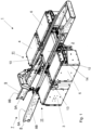
- FIG. 1 the relevant part of an embodiment of a vehicle 1 according to the invention is schematically shown in perspective.
- the vehicle 1 is provided with an electric motor 2 (schematically shown) configured to at least partially propel the vehicle 1.
- the vehicle 1 has a vehicle battery comprising four battery modules 3, 4, 5, 6 each comprising battery packs configured to at least partially power the electric motor. It will be clear that the invention is not limited to the number of battery modules provided that at least one battery module are present.
- the vehicle 1 further comprises a chassis 7 comprising a first elongate chassis beam 8 and a second elongate chassis beam 9, both extending along a length of the vehicle 1, and at least one cross beam 10 connecting the first elongate chassis beam 8 and the second elongate chassis beam 9.
- a front side of the vehicle 1 is shown at the left hand side of the figure, whilst a rear side of the vehicle 1 is shown at the right hand side of figure 1 .
- the vehicle 1 further comprises a battery mounting system 11 for mounting the vehicle battery to the chassis 7.
- Each of the first and second elongate chassis beam 8, 9 comprising an inner surface 8A, 9A and an outer surface 8B, 9B.
- the inner surfaces 8A, 9A of the first and second chassis beams 8, 9 facing each other while the outer surfaces 8B, 9B of the first and second chassis beams 8, 9 are facing away from each other.
- a first battery module 3 and a second battery module 4 are arranged on a respective outer surface 8B, 9B of the first and second elongate chassis beam 8, 9, respectively, i.e. the battery modules 3 and 4 are positioned on the outer sides of the chassis beams 8, 9.
- a third battery module 5 and a fourth battery module 6 are arranged on a respective outer surface 8B, 9B of the first and second elongate chassis beam 8, 9, respectively, i.e. the battery modules 5 and 6 are positioned on the outer sides of the chassis beams 8, 9.
- “horizontal” and “vertical” have the usual meaning referring to a normal operational mode in which the vehicle 1 is supported on a horizontal road surface.
- front and “rear” are defined in the manner that “front” refers to the normal driving direction of the vehicle 1, which as shown in Figure 1 is to the left.
- the battery mounting system 11 comprises a similar construction, which will be described in more detail with regard to construction for the third module 5 below.
- the battery mounting system 11 comprises a battery box 12 configured to hold and support the battery packs of the third battery module 5.
- the battery mounting system 11 comprises a front bracket 13 mounted to and projecting from the first elongate chassis beam 8 away from the second elongate chassis beam 9 and a posterior bracket 14 mounted to and projecting from the first elongate chassis beam 8 away from the second elongate chassis beam 9.
- the posterior bracket 14 is spaced apart from the front bracket 13 in a direction opposite to the normal driving direction and therefore is called the posterior bracket.
- the battery box 12 is connected to and positioned between the front bracket 13 and the posterior bracket 14.
- the front and posterior brackets 13, 14 can be of the same construction, which construction is below described in more detail with regard to the posterior bracket 14 as shown in Figure 2 .
- the bracket 14 is a triangularly shaped bracket comprising a chassis beam attachment portion 15 for connecting the triangularly shaped bracket 14 to the outer surface 8B of the elongate chassis beam 8, an upper horizontal portion 16 and an angled portion 17 extending downwardly between a front end of the upper horizontal portion 16 towards the elongate chassis beam 8.
- the chassis beam attachment portion 15 is planar.
- At least the upper horizontal portion 16 comprises means, in the shown embodiment indicate by holes for receiving connectors, with which the battery box can be received by or mounted on the bracket 14.
- the vehicle 1 comprises a suspension 18 for the electric motor 2 for suspending the electric motor 2 in between the first elongate chassis beam 8 and the second elongate chassis beam 9.
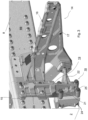
- the suspension 18 for the electric motor 2 for each of the triangularly shaped brackets comprises an electric motor bracket 19 having a flat flange 20 mounted on the planar chassis beam attachment portion 15 of the respective triangularly shaped bracket, the bracket 14 as shown in Figure 3 .
- the suspension for the battery box and the electric motor have an overlap at the position of the flat flange 20 of the electric motor bracket 19 and the planar chassis beam attachment portion 15 of the respective triangularly shaped bracket 14.
- the planar chassis beam attachment portion 15 of the triangularly shaped bracket 14 provides a stiff surface for the flat flange 20 of the electric motor bracket 19 diverging load away from the elongate chassis beam 8. Since in accordance with the invention the flat flange 20 is mounted on the planar chassis beam attachment portion 15 of the triangularly shaped bracket 14 which is mounted to the chassis beam 8, it is observed that the electric motor 2 is not suspended or carried by the triangularly shaped bracket 14 and thus the electric motor 2 does not generate any loads on the triangularly shaped bracket 14.
- the electric motor bracket 19 and the triangularly shaped bracket 14 can be pre-assembled as a result of which mounting of the electric motor 2 and the battery box 12 can be effected relatively easy.
- the suspension for the electric motor 2 comprises removable vibration dampers 24 for suspending the electric motor 2 to the electric motor bracket 19.
- the vibration dampers 24 can be separated from the bracket 19 and the electric motor 2 can be easily removed in a downward direction which is especially useful for service, in particular when the vehicle is a tractor or truck with non removeable components, i.e. chassis frame, rigid body or any other construction which is fixed to the chassis frame .
- the flat flange 20 of the electric motor bracket 19 has a downward extension part 21 to which the electric motor 2 is connected while further a cross brace 22 is connected between the downward extension part 21 of the electric motor bracket 19 and the triangularly shaped bracket 14, wherein the cross brace 22 extends in a substantial horizontally direction.
- the cross brace 22 extends at least substantially transverse to the triangularly shaped bracket 14 as a result of which vibrations from the electric motor 2 and the battery box are transferred in a lesser extent to the chassis beam 8 without any load transfer of the electric motor 2 to the triangularly shaped bracket 14 and vice versa.
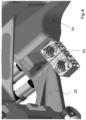
- FIG 4 an embodiment of the vehicle 1 according to the invention is shown in which the cross brace 22 is provided with holding means 23 for high voltage cables.
- holding means 23 for high voltage cables an electric motor 2 can be relatively easily installed on the chassis 7.
- the cross brace can alternatively or additionally also be provided with holding means for cooling water hoses.
- FIG. 5 an embodiment of a vehicle according to the invention is shown in which a battery module 3 (schematically indicated) is arranged on one side of the chassis 7 only, i.e. in the shown embodiment the battery module 3 is arranged on the outer surface 8B of the first elongate chassis beam 8 by means of a front and a posterior triangularly shaped bracket 13, 14.
- the suspension for the electric motor 2 comprises a further electric motor bracket 30 having a flat flange 31 mounted directly to the outer surface 9B of the second elongate chassis beam 9.
- the flat flange 31 of the further electric motor bracket 30 has a downward extension part 32 to which the electric motor is connected such that the electric motor is suspended between the downward extension part 21 of the electric motor bracket 19 and the downward extension part 32 of the further electric motor bracket 30.
- the battery mounting system in addition comprises an elongated cross member 33 connected between the triangularly shaped bracket 14 arranged on the outer surface 8B of the first elongate chassis beam 8 and the downward extension part 32 of the further electric motor bracket 30, providing an increased stiffness for the battery module mounting system.
- the elongated cross member 33 is also connected to the inner surface 8A of the first elongate chassis beam 8 at position C and likewise to the inner surface of the second elongate chassis beam 9 for providing additional stiffness which results in less battery damage.
Landscapes
- Engineering & Computer Science (AREA)
- Chemical & Material Sciences (AREA)
- Combustion & Propulsion (AREA)
- Transportation (AREA)
- Mechanical Engineering (AREA)
- Arrangement Or Mounting Of Propulsion Units For Vehicles (AREA)
- Body Structure For Vehicles (AREA)
Abstract
Description
- The invention relates to a vehicle provided with an electric motor configured to at least partially propel the vehicle, a vehicle battery at least comprising a battery module, said battery module comprising battery packs configured to at least partially power the electric motor, and a chassis comprising a first elongate chassis beam and a second elongate chassis beam, both extending along a length of the vehicle, each first and second elongate chassis beam comprising an inner surface and an outer surface, the inner surfaces of the first and second chassis beams facing each other, the outer surfaces of the first and second chassis beams facing away from each other, and at least one cross beam connecting the first elongate chassis beam and the second elongate chassis beam, wherein the battery module is arranged on an outer surface of the first and second elongate chassis beam, respectively;
- wherein the vehicle further comprises a battery mounting system for mounting the vehicle battery to the chassis, the battery mounting system for the battery module comprises:
- a battery box configured to hold and support the battery packs of the battery module;
- a front bracket mounted to and projecting from the outer surface of the respective elongate chassis beam; and
- a posterior bracket mounted to and projecting from the outer surface of the respective elongate chassis beam such that the posterior bracket is spaced apart from the front bracket for receiving the respective battery box between the front bracket and the posterior bracket;
- wherein each of the brackets is a triangularly shaped bracket comprising a chassis beam attachment portion for connecting the triangularly shaped bracket to an outer surface of an elongate chassis beam, an upper horizontal portion and an angled portion extending downwardly between a front end of the upper horizontal portion towards the respective elongate chassis beam, wherein the chassis beam attachment portion of the triangularly shaped brackets is planar. Such a vehicle provided with an electric motor is disclosed in the co-pending
Dutch patent application NL2031489 - In vehicles provided with an electric motor and battery packs mounted to the elongate chassis beams of the chassis, the total weight of the components is relatively high, which weight can result in increased vibration and/or shear stresses which are transferred to the chassis when the vehicle is in motion when compared to vehicle provided with an internal combustion engine.
- It is an object of the invention to provide a vehicle with an electric motor in which the battery packs and the electric motor are suspended such that the transference of vibrations and/or shear stresses to the chassis is kept within acceptable limits.
- According to the invention this object is obtained by providing a vehicle provided with an electric motor configured to at least partially propel the vehicle, a vehicle battery at least comprising a battery module, said battery module comprising battery packs configured to at least partially power the electric motor, and a chassis comprising a first elongate chassis beam and a second elongate chassis beam, both extending along a length of the vehicle, each first and second elongate chassis beam comprising an inner surface and an outer surface, the inner surfaces of the first and second chassis beams facing each other, the outer surfaces of the first and second chassis beams facing away from each other, and at least one cross beam connecting the first elongate chassis beam and the second elongate chassis beam, wherein the battery module is arranged on an outer surface of the first and second elongate chassis beam, respectively;
- wherein the vehicle further comprises a battery mounting system for mounting the vehicle battery to the chassis, the battery mounting system for the battery module comprises:
- a battery box configured to hold and support the battery packs of the battery module;
- a front bracket mounted to and projecting from the outer surface of the respective elongate chassis beam; and
- a posterior bracket mounted to and projecting from the outer surface of the respective elongate chassis beam such that the posterior bracket is spaced apart from the front bracket for receiving the respective battery box between the front bracket and the posterior bracket;
- wherein each of the brackets is a triangularly shaped bracket comprising a chassis beam attachment portion for connecting the triangularly shaped bracket to an outer surface of an elongate chassis beam, an upper horizontal portion and an angled portion extending downwardly between a front end of the upper horizontal portion towards the respective elongate chassis beam, wherein the chassis beam attachment portion of the triangularly shaped brackets is planar, characterized in that
- the vehicle further comprises a suspension for the electric motor for suspending the electric motor in between the first elongate chassis beam and the second elongate chassis beam; and in that the suspension for the electric motor comprises at least one electric motor bracket, said at least one electric motor bracket having a flat flange mounted on the planar chassis beam attachment portion of a respective triangularly shaped bracket. In this manner the suspension for the battery box and the electric motor have an overlap at the position of the flat flange of the electric motor bracket and the planar chassis beam attachment portion of a respective triangularly shaped bracket as a result of which the planar chassis beam attachment portion of a respective triangularly shaped bracket provides a stiff surface for the flat flange of the electric motor bracket diverging load away from the elongate chassis beams. In case, in contrast, the flat flange of the electric motor bracket and the planar chassis beam attachment portion of a respective triangularly shaped bracket would not overlap, i.e. in case the flat flange of the electric motor bracket and the planar chassis beam attachment portion of a respective triangularly shaped bracket would be attached to the respective chassis beam at spaced locations both the flat flange of the electric motor bracket and the planar chassis beam attachment portion of a respective triangularly shaped bracket would transfer high loads to the chassis as a result of which the chassis beam could shear. Since in accordance with the invention the flat flange is mounted on the planar chassis beam attachment portion of a respective triangularly shaped bracket, which planar chassis beam attachment portion of a respective triangularly shaped bracket is mounted to the chassis beam, it is observed that the electric motor is not suspended or carried by the respective triangularly shaped bracket and thus the electric motor does not generate any loads on the respective triangularly shaped bracket.
- In an embodiment of a vehicle provided with an electric motor according to the invention the suspension for the electric motor comprises removable vibration dampers for suspending the electric motor to the electric motor bracket. By using removable vibration dampers the electric motor can be easily removed in a downward direction which is especially useful for service.
- In an embodiment of a vehicle with an electric motor according to the invention the flat flange of the electric motor bracket has a downward extension part to which the electric motor is connected and wherein a cross brace is connected between the downward extension part of the electric motor bracket and the respective triangularly shaped bracket, the cross brace extending substantially horizontally. By connecting a horizontal cross brace between the downward extension part of the electric motor bracket and the respective triangularly shaped bracket, i.e. the cross brace extends at least substantially transverse to the respective triangularly shaped bracket, it appears that vibrations from the electric motor and the battery box are transferred in a lesser extent to the respective chassis beam without any load transfer of the electric motor to the respective triangularly shaped bracket and vice versa, since by the horizontal extension of the cross brace the electric motor is not suspended to the respective triangularly shaped bracket.
- In a further embodiment of a vehicle with an electric motor according to the invention the cross brace is provided with holding means for high voltage cables and/or cooling water hoses. By providing holding means for high voltage cables and/or cooling water hoses an electric motor can be relatively easily installed on the chassis. It is in addition observed here that the electric motor bracket having a flat flange and the triangularly shaped bracket having the planar chassis beam attachment portion can be pre-assembled as a result of which mounting of the electric motor and the battery box can be effected relatively easy.
- In a still further embodiment of a vehicle provided with an electric motor according to the invention in which the battery module is arranged on one of the outer surface of the first elongate chassis beam and the second elongate chassis beam only, the suspension for the electric motor comprises a further electric motor bracket having a flat flange mounted directly to the outer surface of the other one of the outer surface of the first elongate chassis beam and the second elongate chassis beam. Preferably, the flat flange of the further electric motor bracket has a downward extension part to which the electric motor is connected. In case the battery mounting system comprises an elongated cross member connected between the triangularly shaped bracket arranged on the one of the outer surface of the first elongate chassis beam and the second elongate chassis beam and the downward extension part of the further electric motor bracket, increased stiffness for the battery module mounting system is provided. The stiffness is increased even further when the elongated cross member is also connected to the inner surfaces of the first and the second elongate chassis beams.
- The invention will be further explained with reference to the Figures, in which non-limiting exemplary embodiments of a vehicle according to the invention are schematically shown.
-
-
Figure 1 schematically shows in perspective a vehicle provided with an electric motor, a vehicle battery at least comprising a battery module, a chassis and a battery mounting system with triangularly shaped brackets according to the invention; -
Figure 2 schematically shows a triangularly shaped bracket of the vehicle ofFigure 1 comprising a planar chassis beam attachment portion; -
Figure 3 schematically shows an electric motor bracket having a flat flange mounted on the planar chassis beam attachment portion of the triangularly shaped bracket ofFigure 2 ; -
Figure 4 schematically shows an embodiment of the invention in which the electric motor bracket comprises a cross brace provided with holding means for high voltage cables; and -
Figure 5 schematically shows an embodiment of the invention in which the battery modules are arranged on one side of the chassis only. - In
Figure 1 the relevant part of an embodiment of avehicle 1 according to the invention is schematically shown in perspective. Thevehicle 1 is provided with an electric motor 2 (schematically shown) configured to at least partially propel thevehicle 1. In the embodiment shown inFigure 1 , thevehicle 1 has a vehicle battery comprising fourbattery modules vehicle 1 further comprises achassis 7 comprising a firstelongate chassis beam 8 and a secondelongate chassis beam 9, both extending along a length of thevehicle 1, and at least onecross beam 10 connecting the firstelongate chassis beam 8 and the secondelongate chassis beam 9. A front side of thevehicle 1 is shown at the left hand side of the figure, whilst a rear side of thevehicle 1 is shown at the right hand side offigure 1 . Thevehicle 1 further comprises abattery mounting system 11 for mounting the vehicle battery to thechassis 7. Each of the first and secondelongate chassis beam inner surface outer surface inner surfaces second chassis beams outer surfaces second chassis beams Figure 1 afirst battery module 3 and asecond battery module 4 are arranged on a respectiveouter surface elongate chassis beam battery modules chassis beams third battery module 5 and afourth battery module 6 are arranged on a respectiveouter surface elongate chassis beam battery modules chassis beams vehicle 1 is supported on a horizontal road surface. Further, "front" and "rear" are defined in the manner that "front" refers to the normal driving direction of thevehicle 1, which as shown inFigure 1 is to the left. - For each of the
battery modules battery mounting system 11 comprises a similar construction, which will be described in more detail with regard to construction for thethird module 5 below. - The
battery mounting system 11 comprises abattery box 12 configured to hold and support the battery packs of thethird battery module 5. As can be seen inFigure 1 for thethird battery module 5 thebattery mounting system 11 comprises afront bracket 13 mounted to and projecting from the firstelongate chassis beam 8 away from the secondelongate chassis beam 9 and aposterior bracket 14 mounted to and projecting from the firstelongate chassis beam 8 away from the secondelongate chassis beam 9. Theposterior bracket 14 is spaced apart from thefront bracket 13 in a direction opposite to the normal driving direction and therefore is called the posterior bracket. Thebattery box 12 is connected to and positioned between thefront bracket 13 and theposterior bracket 14. The front andposterior brackets posterior bracket 14 as shown inFigure 2 . - As can be seen in
Figure 2 thebracket 14 is a triangularly shaped bracket comprising a chassisbeam attachment portion 15 for connecting the triangularlyshaped bracket 14 to theouter surface 8B of theelongate chassis beam 8, an upperhorizontal portion 16 and anangled portion 17 extending downwardly between a front end of the upperhorizontal portion 16 towards theelongate chassis beam 8. As can be seen inFigure 2 the chassisbeam attachment portion 15 is planar. At least the upperhorizontal portion 16 comprises means, in the shown embodiment indicate by holes for receiving connectors, with which the battery box can be received by or mounted on thebracket 14. - According to the invention the
vehicle 1 comprises asuspension 18 for theelectric motor 2 for suspending theelectric motor 2 in between the firstelongate chassis beam 8 and the secondelongate chassis beam 9. Thesuspension 18 for theelectric motor 2 for each of the triangularly shaped brackets comprises anelectric motor bracket 19 having aflat flange 20 mounted on the planar chassisbeam attachment portion 15 of the respective triangularly shaped bracket, thebracket 14 as shown inFigure 3 . In this manner the suspension for the battery box and the electric motor have an overlap at the position of theflat flange 20 of theelectric motor bracket 19 and the planar chassisbeam attachment portion 15 of the respective triangularly shapedbracket 14. As a result of this construction the planar chassisbeam attachment portion 15 of the triangularlyshaped bracket 14 provides a stiff surface for theflat flange 20 of theelectric motor bracket 19 diverging load away from theelongate chassis beam 8. Since in accordance with the invention theflat flange 20 is mounted on the planar chassisbeam attachment portion 15 of the triangularlyshaped bracket 14 which is mounted to thechassis beam 8, it is observed that theelectric motor 2 is not suspended or carried by the triangularlyshaped bracket 14 and thus theelectric motor 2 does not generate any loads on the triangularlyshaped bracket 14. Theelectric motor bracket 19 and the triangularly shapedbracket 14 can be pre-assembled as a result of which mounting of theelectric motor 2 and thebattery box 12 can be effected relatively easy. As indicated inFigure 3 the suspension for theelectric motor 2 comprises removable vibration dampers 24 for suspending theelectric motor 2 to theelectric motor bracket 19. By loosening thebolts 25 the vibration dampers 24 can be separated from thebracket 19 and theelectric motor 2 can be easily removed in a downward direction which is especially useful for service, in particular when the vehicle is a tractor or truck with non removeable components, i.e. chassis frame, rigid body or any other construction which is fixed to the chassis frame . - In the embodiment of a
vehicle 1 with anelectric motor 2 according to the invention as shown inFigure 3 , theflat flange 20 of theelectric motor bracket 19 has adownward extension part 21 to which theelectric motor 2 is connected while further across brace 22 is connected between thedownward extension part 21 of theelectric motor bracket 19 and the triangularly shapedbracket 14, wherein thecross brace 22 extends in a substantial horizontally direction. In this manner thecross brace 22 extends at least substantially transverse to the triangularly shapedbracket 14 as a result of which vibrations from theelectric motor 2 and the battery box are transferred in a lesser extent to thechassis beam 8 without any load transfer of theelectric motor 2 to the triangularly shapedbracket 14 and vice versa. - In
Figure 4 an embodiment of thevehicle 1 according to the invention is shown in which thecross brace 22 is provided with holding means 23 for high voltage cables. By providing holding means 23 for high voltage cables anelectric motor 2 can be relatively easily installed on thechassis 7. It is observed here that the cross brace can alternatively or additionally also be provided with holding means for cooling water hoses. - In
Figure 5 an embodiment of a vehicle according to the invention is shown in which a battery module 3 (schematically indicated) is arranged on one side of thechassis 7 only, i.e. in the shown embodiment thebattery module 3 is arranged on theouter surface 8B of the firstelongate chassis beam 8 by means of a front and a posterior triangularly shapedbracket electric motor 2 comprises a furtherelectric motor bracket 30 having aflat flange 31 mounted directly to theouter surface 9B of the secondelongate chassis beam 9. Theflat flange 31 of the furtherelectric motor bracket 30 has adownward extension part 32 to which the electric motor is connected such that the electric motor is suspended between thedownward extension part 21 of theelectric motor bracket 19 and thedownward extension part 32 of the furtherelectric motor bracket 30. In the embodiment shown inFigure 5 the battery mounting system in addition comprises anelongated cross member 33 connected between the triangularly shapedbracket 14 arranged on theouter surface 8B of the firstelongate chassis beam 8 and thedownward extension part 32 of the furtherelectric motor bracket 30, providing an increased stiffness for the battery module mounting system. As indicated inFigure 5 theelongated cross member 33 is also connected to theinner surface 8A of the firstelongate chassis beam 8 at position C and likewise to the inner surface of the secondelongate chassis beam 9 for providing additional stiffness which results in less battery damage.
Claims (8)
- A vehicle provided with an electric motor configured to at least partially propel the vehicle, a vehicle battery at least comprising a battery module, said battery module comprising battery packs configured to at least partially power the electric motor, and a chassis comprising a first elongate chassis beam and a second elongate chassis beam, both extending along a length of the vehicle, each first and second elongate chassis beam comprising an inner surface and an outer surface, the inner surfaces of the first and second chassis beams facing each other, the outer surfaces of the first and second chassis beams facing away from each other, and at least one cross beam connecting the first elongate chassis beam and the second elongate chassis beam, wherein the battery module is arranged on an outer surface of the first and second elongate chassis beam, respectively;wherein the vehicle further comprises a battery mounting system for mounting the vehicle battery to the chassis, the battery mounting system for the battery module comprises:- a battery box configured to hold and support the battery packs of the battery module;- a front bracket mounted to and projecting from the outer surface of the respective elongate chassis beam; and- a posterior bracket mounted to and projecting from the outer surface of the respective elongate chassis beam such that the posterior bracket is spaced apart from the front bracket for receiving the respective battery box between the front bracket and the posterior bracket;wherein each of the brackets is a triangularly shaped bracket comprising a chassis beam attachment portion for connecting the triangularly shaped bracket to an outer surface of an elongate chassis beam, an upper horizontal portion and an angled portion extending downwardly between a front end of the upper horizontal portion towards the respective elongate chassis beam, wherein the chassis beam attachment portion of the triangularly shaped brackets is planar, characterized in thatthe vehicle further comprises a suspension for the electric motor for suspending the electric motor in between the first elongate chassis beam and the second elongate chassis beam; and in that the suspension for the electric motor comprises at least one electric motor bracket, said at least one electric motor bracket having a flat flange mounted on the planar chassis beam attachment portion of a respective triangularly shaped bracket.
- The vehicle provided with an electric motor according to claim 1, wherein the suspension for the electric motor comprises removable vibration dampers for suspending the electric motor to the electric motor bracket.
- The vehicle provided with an electric motor according to claim 1 or 2, wherein the flat flange of the electric motor bracket has a downward extension part and wherein a cross brace is connected between the downward extension part of the electric motor bracket and the respective triangularly shaped bracket, the cross brace extending substantially horizontally.
- The vehicle provided with an electric motor according to claim 3, wherein the cross brace is provided with holding means for high voltage cables and/or cooling water hoses.
- The vehicle provided with an electric motor according to any one of the preceding claims, wherein the battery module is arranged on one of the outer surface of the first elongate chassis beam and the second elongate chassis beam only, wherein the suspension for the electric motor comprises a further electric motor bracket having a flat flange mounted directly to the outer surface of the other one of the outer surface of the first elongate chassis beam and the second elongate chassis beam.
- The vehicle provided with an electric motor according to claim 5, wherein the flat flange of the further electric motor bracket has a downward extension part to which the electric motor is connected.
- The vehicle provided with an electric motor according to claim 6, wherein the battery mounting system comprises an elongated cross member connected between the triangularly shaped bracket arranged on the one of the outer surface of the first elongate chassis beam and the second elongate chassis beam and the downward extension part of the further electric motor bracket.
- The vehicle provided with an electric motor according to claim 7, wherein the elongated cross member is also connected to the inner surfaces of the first and the second elongate chassis beams.
Applications Claiming Priority (1)
| Application Number | Priority Date | Filing Date | Title |
|---|---|---|---|
| NL2033240A NL2033240B1 (en) | 2022-10-05 | 2022-10-05 | A vehicle provided with an electric motor. |
Publications (3)
| Publication Number | Publication Date |
|---|---|
| EP4349626A1 true EP4349626A1 (en) | 2024-04-10 |
| EP4349626C0 EP4349626C0 (en) | 2025-01-22 |
| EP4349626B1 EP4349626B1 (en) | 2025-01-22 |
Family
ID=84462499
Family Applications (1)
| Application Number | Title | Priority Date | Filing Date |
|---|---|---|---|
| EP23201546.1A Active EP4349626B1 (en) | 2022-10-05 | 2023-10-04 | A vehicle provided with an electric motor |
Country Status (2)
| Country | Link |
|---|---|
| EP (1) | EP4349626B1 (en) |
| NL (1) | NL2033240B1 (en) |
Cited By (2)
| Publication number | Priority date | Publication date | Assignee | Title |
|---|---|---|---|---|
| EP4653217A1 (en) * | 2024-05-23 | 2025-11-26 | Volvo Truck Corporation | Battery multipack torque reduction |
| EP4737153A1 (en) * | 2024-10-29 | 2026-05-06 | Volvo Truck Corporation | Battery suspension arrangement with diagonally arranged bushings |
Citations (6)
| Publication number | Priority date | Publication date | Assignee | Title |
|---|---|---|---|---|
| CN103863080A (en) * | 2014-03-28 | 2014-06-18 | 安徽江淮汽车股份有限公司 | Electric commercial vehicle and electric commercial vehicle split battery pack fixing device |
| CN105438262A (en) * | 2015-12-17 | 2016-03-30 | 苏州奥杰汽车技术股份有限公司 | Novel electric truck chassis structure |
| CN105932191A (en) * | 2016-07-08 | 2016-09-07 | 安徽江淮汽车股份有限公司 | Battery fixing device and electric vehicle |
| DE102017002198A1 (en) * | 2017-03-07 | 2018-09-13 | Daimler Ag | Drive train for a motor vehicle, in particular for a commercial vehicle |
| CN113815394A (en) * | 2020-06-16 | 2021-12-21 | 沃尔沃卡车集团 | Battery module support device |
| EP3925808A1 (en) * | 2020-06-16 | 2021-12-22 | Volvo Truck Corporation | Chassis arrangement for electrified heavy vehicle and electrified heavy vehicle |
-
2022
- 2022-10-05 NL NL2033240A patent/NL2033240B1/en active
-
2023
- 2023-10-04 EP EP23201546.1A patent/EP4349626B1/en active Active
Patent Citations (6)
| Publication number | Priority date | Publication date | Assignee | Title |
|---|---|---|---|---|
| CN103863080A (en) * | 2014-03-28 | 2014-06-18 | 安徽江淮汽车股份有限公司 | Electric commercial vehicle and electric commercial vehicle split battery pack fixing device |
| CN105438262A (en) * | 2015-12-17 | 2016-03-30 | 苏州奥杰汽车技术股份有限公司 | Novel electric truck chassis structure |
| CN105932191A (en) * | 2016-07-08 | 2016-09-07 | 安徽江淮汽车股份有限公司 | Battery fixing device and electric vehicle |
| DE102017002198A1 (en) * | 2017-03-07 | 2018-09-13 | Daimler Ag | Drive train for a motor vehicle, in particular for a commercial vehicle |
| CN113815394A (en) * | 2020-06-16 | 2021-12-21 | 沃尔沃卡车集团 | Battery module support device |
| EP3925808A1 (en) * | 2020-06-16 | 2021-12-22 | Volvo Truck Corporation | Chassis arrangement for electrified heavy vehicle and electrified heavy vehicle |
Cited By (2)
| Publication number | Priority date | Publication date | Assignee | Title |
|---|---|---|---|---|
| EP4653217A1 (en) * | 2024-05-23 | 2025-11-26 | Volvo Truck Corporation | Battery multipack torque reduction |
| EP4737153A1 (en) * | 2024-10-29 | 2026-05-06 | Volvo Truck Corporation | Battery suspension arrangement with diagonally arranged bushings |
Also Published As
| Publication number | Publication date |
|---|---|
| EP4349626C0 (en) | 2025-01-22 |
| EP4349626B1 (en) | 2025-01-22 |
| NL2033240B1 (en) | 2024-04-18 |
Similar Documents
| Publication | Publication Date | Title |
|---|---|---|
| CN113815394B (en) | Battery module support device | |
| EP4349626B1 (en) | A vehicle provided with an electric motor | |
| GB2567542B (en) | Electric vehicle | |
| US7874395B2 (en) | Electric motor mounting structure for vehicles | |
| CN102686430B (en) | Motor vehicles comprising electric generator sets and their power supply modules arranged near the running gear of the vehicle | |
| US9828031B2 (en) | Motor vehicle and rear-end module therefor | |
| US8534411B2 (en) | General-purpose frame structure for mounting powerplants | |
| US12030374B2 (en) | Bearing arrangement of a component on an axle carrier for a motor vehicle, and motor vehicle, in particular passenger car | |
| CN114987615A (en) | Frame structure for vehicle | |
| US12049131B2 (en) | Electric truck frame | |
| US20210379976A1 (en) | Unit mounting | |
| CN104709060B (en) | Motor/transmission for motor vehicle supports | |
| JP2005505471A (en) | Vehicle body | |
| US9333845B2 (en) | Vehicle mounted fuel cell assembly | |
| US20240010079A1 (en) | Cross beam, motor vehicle and method of mounting an assembly | |
| EP4366968B1 (en) | A suspension arrangement for an energy storage system | |
| EP4257454B1 (en) | Road vehicle with battery mounting arrangement | |
| NL2028364B1 (en) | Pre-assembled Electric Power Module | |
| JP2012121522A (en) | Power train support device | |
| CN112278082B (en) | Mounting bracket for improving the dynamic stiffness of the subframe suspension attachment of hydrogen vehicles | |
| HU225484B1 (en) | Supporting structure of driving apparatus particularly for rear-engined buses | |
| JP3134708B2 (en) | Power plant support structure | |
| CN215153882U (en) | Vehicle body structure | |
| CN222756411U (en) | Suspension mechanism and off-highway mining dump truck | |
| JP2013119318A (en) | Vehicle body front structure |
Legal Events
| Date | Code | Title | Description |
|---|---|---|---|
| PUAI | Public reference made under article 153(3) epc to a published international application that has entered the european phase |
Free format text: ORIGINAL CODE: 0009012 |
|
| STAA | Information on the status of an ep patent application or granted ep patent |
Free format text: STATUS: THE APPLICATION HAS BEEN PUBLISHED |
|
| AK | Designated contracting states |
Kind code of ref document: A1 Designated state(s): AL AT BE BG CH CY CZ DE DK EE ES FI FR GB GR HR HU IE IS IT LI LT LU LV MC ME MK MT NL NO PL PT RO RS SE SI SK SM TR |
|
| STAA | Information on the status of an ep patent application or granted ep patent |
Free format text: STATUS: REQUEST FOR EXAMINATION WAS MADE |
|
| 17P | Request for examination filed |
Effective date: 20240418 |
|
| RBV | Designated contracting states (corrected) |
Designated state(s): AL AT BE BG CH CY CZ DE DK EE ES FI FR GB GR HR HU IE IS IT LI LT LU LV MC ME MK MT NL NO PL PT RO RS SE SI SK SM TR |
|
| GRAP | Despatch of communication of intention to grant a patent |
Free format text: ORIGINAL CODE: EPIDOSNIGR1 |
|
| STAA | Information on the status of an ep patent application or granted ep patent |
Free format text: STATUS: GRANT OF PATENT IS INTENDED |
|
| INTG | Intention to grant announced |
Effective date: 20240807 |
|
| GRAS | Grant fee paid |
Free format text: ORIGINAL CODE: EPIDOSNIGR3 |
|
| GRAA | (expected) grant |
Free format text: ORIGINAL CODE: 0009210 |
|
| STAA | Information on the status of an ep patent application or granted ep patent |
Free format text: STATUS: THE PATENT HAS BEEN GRANTED |
|
| AK | Designated contracting states |
Kind code of ref document: B1 Designated state(s): AL AT BE BG CH CY CZ DE DK EE ES FI FR GB GR HR HU IE IS IT LI LT LU LV MC ME MK MT NL NO PL PT RO RS SE SI SK SM TR |
|
| REG | Reference to a national code |
Ref country code: GB Ref legal event code: FG4D |
|
| REG | Reference to a national code |
Ref country code: CH Ref legal event code: EP |
|
| REG | Reference to a national code |
Ref country code: IE Ref legal event code: FG4D |
|
| REG | Reference to a national code |
Ref country code: DE Ref legal event code: R096 Ref document number: 602023001766 Country of ref document: DE |
|
| U01 | Request for unitary effect filed |
Effective date: 20250128 |
|
| U07 | Unitary effect registered |
Designated state(s): AT BE BG DE DK EE FI FR IT LT LU LV MT NL PT RO SE SI Effective date: 20250203 |
|
| PG25 | Lapsed in a contracting state [announced via postgrant information from national office to epo] |
Ref country code: RS Free format text: LAPSE BECAUSE OF FAILURE TO SUBMIT A TRANSLATION OF THE DESCRIPTION OR TO PAY THE FEE WITHIN THE PRESCRIBED TIME-LIMIT Effective date: 20250422 |
|
| PG25 | Lapsed in a contracting state [announced via postgrant information from national office to epo] |
Ref country code: PL Free format text: LAPSE BECAUSE OF FAILURE TO SUBMIT A TRANSLATION OF THE DESCRIPTION OR TO PAY THE FEE WITHIN THE PRESCRIBED TIME-LIMIT Effective date: 20250122 |
|
| PG25 | Lapsed in a contracting state [announced via postgrant information from national office to epo] |
Ref country code: ES Free format text: LAPSE BECAUSE OF FAILURE TO SUBMIT A TRANSLATION OF THE DESCRIPTION OR TO PAY THE FEE WITHIN THE PRESCRIBED TIME-LIMIT Effective date: 20250122 |
|
| PG25 | Lapsed in a contracting state [announced via postgrant information from national office to epo] |
Ref country code: IS Free format text: LAPSE BECAUSE OF FAILURE TO SUBMIT A TRANSLATION OF THE DESCRIPTION OR TO PAY THE FEE WITHIN THE PRESCRIBED TIME-LIMIT Effective date: 20250522 Ref country code: NO Free format text: LAPSE BECAUSE OF FAILURE TO SUBMIT A TRANSLATION OF THE DESCRIPTION OR TO PAY THE FEE WITHIN THE PRESCRIBED TIME-LIMIT Effective date: 20250422 |
|
| PG25 | Lapsed in a contracting state [announced via postgrant information from national office to epo] |
Ref country code: HR Free format text: LAPSE BECAUSE OF FAILURE TO SUBMIT A TRANSLATION OF THE DESCRIPTION OR TO PAY THE FEE WITHIN THE PRESCRIBED TIME-LIMIT Effective date: 20250122 |
|
| PG25 | Lapsed in a contracting state [announced via postgrant information from national office to epo] |
Ref country code: GR Free format text: LAPSE BECAUSE OF FAILURE TO SUBMIT A TRANSLATION OF THE DESCRIPTION OR TO PAY THE FEE WITHIN THE PRESCRIBED TIME-LIMIT Effective date: 20250423 |
|
| PG25 | Lapsed in a contracting state [announced via postgrant information from national office to epo] |
Ref country code: SM Free format text: LAPSE BECAUSE OF FAILURE TO SUBMIT A TRANSLATION OF THE DESCRIPTION OR TO PAY THE FEE WITHIN THE PRESCRIBED TIME-LIMIT Effective date: 20250122 |
|
| PG25 | Lapsed in a contracting state [announced via postgrant information from national office to epo] |
Ref country code: CZ Free format text: LAPSE BECAUSE OF FAILURE TO SUBMIT A TRANSLATION OF THE DESCRIPTION OR TO PAY THE FEE WITHIN THE PRESCRIBED TIME-LIMIT Effective date: 20250122 |
|
| PG25 | Lapsed in a contracting state [announced via postgrant information from national office to epo] |
Ref country code: SK Free format text: LAPSE BECAUSE OF FAILURE TO SUBMIT A TRANSLATION OF THE DESCRIPTION OR TO PAY THE FEE WITHIN THE PRESCRIBED TIME-LIMIT Effective date: 20250122 |
|
| PLBE | No opposition filed within time limit |
Free format text: ORIGINAL CODE: 0009261 |
|
| STAA | Information on the status of an ep patent application or granted ep patent |
Free format text: STATUS: NO OPPOSITION FILED WITHIN TIME LIMIT |
|
| U20 | Renewal fee for the european patent with unitary effect paid |
Year of fee payment: 3 Effective date: 20251028 |
|
| 26N | No opposition filed |
Effective date: 20251023 |
|
| PG25 | Lapsed in a contracting state [announced via postgrant information from national office to epo] |
Ref country code: MC Free format text: LAPSE BECAUSE OF FAILURE TO SUBMIT A TRANSLATION OF THE DESCRIPTION OR TO PAY THE FEE WITHIN THE PRESCRIBED TIME-LIMIT Effective date: 20250122 |