EP4349623A1 - Vehicle air-conditioning device - Google Patents
Vehicle air-conditioning device Download PDFInfo
- Publication number
- EP4349623A1 EP4349623A1 EP22837333.8A EP22837333A EP4349623A1 EP 4349623 A1 EP4349623 A1 EP 4349623A1 EP 22837333 A EP22837333 A EP 22837333A EP 4349623 A1 EP4349623 A1 EP 4349623A1
- Authority
- EP
- European Patent Office
- Prior art keywords
- fins
- air
- ridges
- heat radiation
- flow
- Prior art date
- Legal status (The legal status is an assumption and is not a legal conclusion. Google has not performed a legal analysis and makes no representation as to the accuracy of the status listed.)
- Withdrawn
Links
Images




Classifications
-
- B—PERFORMING OPERATIONS; TRANSPORTING
- B60—VEHICLES IN GENERAL
- B60H—ARRANGEMENTS OF HEATING, COOLING, VENTILATING OR OTHER AIR-TREATING DEVICES SPECIALLY ADAPTED FOR PASSENGER OR GOODS SPACES OF VEHICLES
- B60H1/00—Heating, cooling or ventilating devices
- B60H1/00457—Ventilation unit, e.g. combined with a radiator
-
- F—MECHANICAL ENGINEERING; LIGHTING; HEATING; WEAPONS; BLASTING
- F28—HEAT EXCHANGE IN GENERAL
- F28F—DETAILS OF HEAT-EXCHANGE AND HEAT-TRANSFER APPARATUS, OF GENERAL APPLICATION
- F28F3/00—Plate-like or laminated elements; Assemblies of plate-like or laminated elements
- F28F3/02—Elements or assemblies thereof with means for increasing heat-transfer area, e.g. with fins, with recesses, with corrugations
- F28F3/04—Elements or assemblies thereof with means for increasing heat-transfer area, e.g. with fins, with recesses, with corrugations the means being integral with the element
- F28F3/048—Elements or assemblies thereof with means for increasing heat-transfer area, e.g. with fins, with recesses, with corrugations the means being integral with the element in the form of ribs integral with the element or local variations in thickness of the element, e.g. grooves, microchannels
-
- H—ELECTRICITY
- H10—SEMICONDUCTOR DEVICES; ELECTRIC SOLID-STATE DEVICES NOT OTHERWISE PROVIDED FOR
- H10W—GENERIC PACKAGES, INTERCONNECTIONS, CONNECTORS OR OTHER CONSTRUCTIONAL DETAILS OF DEVICES COVERED BY CLASS H10
- H10W40/00—Arrangements for thermal protection or thermal control
- H10W40/20—Arrangements for cooling
- H10W40/22—Arrangements for cooling characterised by their shape, e.g. having conical or cylindrical projections
- H10W40/226—Arrangements for cooling characterised by their shape, e.g. having conical or cylindrical projections characterised by projecting parts, e.g. fins to increase surface area
-
- H—ELECTRICITY
- H10—SEMICONDUCTOR DEVICES; ELECTRIC SOLID-STATE DEVICES NOT OTHERWISE PROVIDED FOR
- H10W—GENERIC PACKAGES, INTERCONNECTIONS, CONNECTORS OR OTHER CONSTRUCTIONAL DETAILS OF DEVICES COVERED BY CLASS H10
- H10W40/00—Arrangements for thermal protection or thermal control
- H10W40/40—Arrangements for thermal protection or thermal control involving heat exchange by flowing fluids
- H10W40/43—Arrangements for thermal protection or thermal control involving heat exchange by flowing fluids by flowing gases, e.g. forced air cooling
-
- B—PERFORMING OPERATIONS; TRANSPORTING
- B60—VEHICLES IN GENERAL
- B60H—ARRANGEMENTS OF HEATING, COOLING, VENTILATING OR OTHER AIR-TREATING DEVICES SPECIALLY ADAPTED FOR PASSENGER OR GOODS SPACES OF VEHICLES
- B60H1/00—Heating, cooling or ventilating devices
- B60H1/00271—HVAC devices specially adapted for particular vehicle parts or components and being connected to the vehicle HVAC unit
- B60H2001/003—Component temperature regulation using an air flow
-
- B—PERFORMING OPERATIONS; TRANSPORTING
- B60—VEHICLES IN GENERAL
- B60H—ARRANGEMENTS OF HEATING, COOLING, VENTILATING OR OTHER AIR-TREATING DEVICES SPECIALLY ADAPTED FOR PASSENGER OR GOODS SPACES OF VEHICLES
- B60H1/00—Heating, cooling or ventilating devices
- B60H1/00507—Details, e.g. mounting arrangements, desaeration devices
- B60H2001/00614—Cooling of electronic units in air stream
Definitions
- the present disclosure relates to a vehicular air conditioning device.
- a fan controller performs voltage control of a fan while radiating heat generated by a power element (MOS-FET, etc.) with a heat radiation fin.
- MOS-FET power element
- Patent Document 1 JP 2020-179769 A
- HVAC vehicular air conditioning device
- a method of increasing the height, width, and length dimensions of a heat radiation fin may be used.
- the size of a flow path in which the heat radiation fin is installed is predetermined depending on the specifications of the HVAC, it is not always possible to sufficiently increase the height, width, and length dimensions of the heat radiation fin.
- pressure loss in the flow path increases accordingly, and thus this method cannot be said to be effective from the viewpoint of flow path resistance.
- the present disclosure has been made in view of such circumstances, and it is an object of the present disclosure to provide a vehicular air conditioning device with which a heat radiation efficiency can be improved without changing the height dimension of a heat radiation fin.
- a vehicular air conditioning device adopts the following means.
- the vehicular air conditioning device includes: a casing including an air inlet and an air outlet, the casing being formed with a flow path communicating with the air inlet and the air outlet; a fan housed in the casing, the fan generating a flow of air from the air inlet to the air outlet through the flow path; a heat generation portion disposed outside the casing; and a heat radiation portion.
- the heat radiation portion includes a base being thermally connected to the heat generation portion and including an installation surface, and a plurality of fins having a plate-like shape.
- the plurality of fins are disposed in the flow path to extend along a flow direction of the air and stand from the installation surface in a direction orthogonal to the flow direction.
- the surfaces of the plurality of fins are provided with a plurality of ridges.
- the plurality of ridges are formed along the flow direction and provided along a standing direction of the plurality of fins.
- a vehicular air conditioning device 1 includes a casing 10 that accommodates devices such as a fan 41 and an evaporator (not illustrated).
- the casing 10 includes an air inlet 11 and an air outlet 12.
- the casing 10 defines a flow path C communicating with the air inlet 11 and the air outlet 12.
- the air inlet 11 is an opening through which air is taken into the casing 10 from the outside of the casing 10.
- the air outlet 12 is an opening through which the air heat-exchanged by the evaporator (not illustrated) is discharged to the outside of the casing 10.
- the flow of air from the air inlet 11 to the air outlet 12 through the flow path C is generated by the fan 41.
- the fan 41 is housed in the casing 10 on the air inlet 11 side.
- the fan 41 is rotationally driven by a motor (not illustrated).
- the rotation of the motor that drives the fan 41 is controlled by a power element (for example, a MOS-FET).
- a power element for example, a MOS-FET
- the power element is a semiconductor element for power control and generates heat when energized. For this reason, when the vehicular air conditioning device 1 is operated, the power element as a heat generation portion is cooled by a heat radiation portion 30.
- a unit 20 including therein the heat generation portion is attached to a wall portion 13 of the casing 10, the wall portion 13 defining the flow path C.
- the unit 20 is disposed outside the wall portion 13 (outside the casing 10).
- the heat radiation portion 30 includes a base 31 and a plurality of fins 32.
- the heat radiation portion 30 is formed of a metal (for example, an aluminum alloy) having an excellent heat conductivity.
- the base 31 is a portion in thermal contact with the heat generation portion (power element) in the heat radiation portion 30. This enables the heat generated by the heat generation portion to be transferred to the heat radiation portion 30.
- the base 31 is formed with an installation surface 31a.
- the installation surface 31a is a surface along the flow direction of air flowing through the flow path C.
- a central portion of the installation surface 31a in a width direction protrudes in a convex shape.
- the protrusion of the central portion is not limited to having a step-like shape as illustrated in FIG. 5 and may have a mountain shape.
- the plurality of fins 32 are provided at the installation surface 31a.
- Each fin 32 is a thin plate-like part extending along the flow direction of air and standing from the installation surface 31a in a direction orthogonal to the flow direction of air.
- the installation surface 31a and the fins 32 are disposed in the flow path C (inside the casing 10).
- the present embodiment adopts the following configuration.
- a plurality of ridges 33 are formed at the side surfaces of the fins 32 which are located along the flow direction of air.
- Each ridge 33 is an elongated protrusion extending along the flow direction of air to be parallel to the installation surface 31a.
- Each ridge 33 is formed continuously and integrally along the flow direction of air. Further, the plurality of ridges 33 are provided over the standing direction of the fin 32 (the vertical direction in FIG. 6 ).
- the surface area of the fins 32 can be increased, and the heat radiation efficiency at the heat radiation portion 30 can be improved.
- the air flowing on the installation surface 31a is made less likely to move in the standing direction of the fins 32 by the presence of the ridges 33 and the flow velocity of the air is slightly reduced by a flow path resistance generated by the ridges 33.
- the separation from a rear half portion (a rear half portion in the flow direction of air) of the installation surface 31a can be suppressed.
- the ridges 33 may be formed over the entire region of the fins 32 in the height direction of the fins 32.
- the surface area of the fins 32 can be increased by making the most of the height dimension (the dimension along the standing direction) of the fins 32.
- the ridges 33 may be omitted at a part of a leading end 32a side and a part of a base end 32b side of each fin 32.
- the ridges 33 are portions that can constitute a flow path resistance in view of the entire flow path C, a pressure loss caused by the fins 32 can be reduced by omitting the ridges 33 in partial regions in the standing direction.
- the ridges 33 may be formed only at a half portion of each fin 32 on the base end 32b side in the standing direction of the fins 32.
- the heat radiation portion 30 configured as described above is made by, for example, extrusion molding. Accordingly, the heat radiation portions 30 having the same cross-sectional shape can be mass-produced.
- the surface area of the fins 32 can be increased and the heat radiation efficiency of the heat radiation portion 30 can be improved.
- the flow of air is maintained on the installation surface 31a (that is, there is no region where the flow velocity is 0 or where air flows backward), and thus a decrease in the heat radiation efficiency at the installation surface 31a and the fins 32 standing from the installation surface 31a can be suppressed.
- the surface area of the fins 32 can be maximized.
- the ridges 33 are not formed at a part of the leading end 32a side and a part of the base end 32b side of each fin 32 in the standing direction of the fins 32, the pressure loss in the part of the leading end 32a side and the part of the base end 32b side can be suppressed. Accordingly, the pressure loss of the entire flow path C can be suppressed.
- a vehicular air conditioning device includes: a casing (10) including an air inlet (11) and an air outlet (12), the casing being formed with a flow path (C) communicating with the air inlet and the air outlet; a fan (41) housed in the casing, the fan generating a flow of air from the air inlet to the air outlet through the flow path; a heat generation portion disposed outside the casing; and a heat radiation portion (30).
- the heat radiation portion includes a base (31) being thermally connected to the heat generation portion and including an installation surface (31a), and a plurality of fins (32) having a plate-like shape.
- the plurality of fins are disposed in the flow path to extend along a flow direction of the air and stand from the installation surface in a direction orthogonal to the flow direction.
- the surfaces of the plurality of fins are provided with a plurality of ridges (33).
- the plurality of ridges are formed along the flow direction and provided along a standing direction of the plurality of fins.
- the vehicular air conditioning device includes the casing, the fan, the heat generation portion, and the heat radiation portion.
- the heat radiation portion is thermally connected to the heat generation portion and includes the base including the installation surface, and the plurality of fins having a plate-like shape.
- the plurality of fins are disposed in the flow path to extend along the flow direction of air and stand from the installation surface in the direction orthogonal to the flow direction.
- the surfaces of the plurality of fins are provided with the plurality of ridges.
- the plurality of ridges are formed along the flow direction and provided over the standing direction of the fins. Therefore, the surface area of the fins can be increased, and thus the heat radiation efficiency can be improved.
- the heat generation portion is, for example, a power element that controls the rotation of the fan.
- the plurality of ridges are formed over the entire region in the standing direction of the fins.
- the surface area of the fins can be maximized.
- the plurality of ridges are not formed at a part of the leading end side and a part of the base end side of each fin in the standing direction of the fins.
- the plurality of ridges are not formed at a part of the leading end side and a part of the base end side of each fin in the standing direction of the fins, it is possible to suppress a pressure loss in the part of the leading end side and the part of the base end side. Accordingly, the pressure loss of the entire flow path can be suppressed.
- the plurality of ridges are formed only at a half portion of each fin on the base end side in the standing direction of the fins.
- the plurality of ridges are formed only at a half portion of each fin on the base end side in the standing direction of the fins, it is possible to suppress the separation of air on the base end side and suppress the pressure loss due to the ridges on the leading end side.
- an extending direction of the plurality of ridges is parallel to the installation surface.
- the heat radiation portion can be made by extrusion molding.
Landscapes
- Engineering & Computer Science (AREA)
- Physics & Mathematics (AREA)
- Thermal Sciences (AREA)
- Mechanical Engineering (AREA)
- General Engineering & Computer Science (AREA)
- Air-Conditioning For Vehicles (AREA)
- Cooling Or The Like Of Electrical Apparatus (AREA)
Abstract
Description
- The present disclosure relates to a vehicular air conditioning device.
- In the field of heating ventilation and air conditioning (HVAC) units, such as described in Patent Document 1, a fan controller performs voltage control of a fan while radiating heat generated by a power element (MOS-FET, etc.) with a heat radiation fin.
- Patent Document 1:
JP 2020-179769 A - In recent years, outside temperatures have been increasing and the environmental conditions under which a vehicular air conditioning device (HVAC) is used have been deteriorating. Thus, a fan controller is likely to be affected by the outside temperature, and there is a possibility that an existing heat radiation fin cannot sufficiently radiate heat of a power element.
- Therefore, to improve heat radiation efficiency (heat radiation performance), a method of increasing the height, width, and length dimensions of a heat radiation fin may be used. However, since the size of a flow path in which the heat radiation fin is installed is predetermined depending on the specifications of the HVAC, it is not always possible to sufficiently increase the height, width, and length dimensions of the heat radiation fin. In addition, even when the height, width, and length dimensions are increased, pressure loss in the flow path increases accordingly, and thus this method cannot be said to be effective from the viewpoint of flow path resistance.
- The present disclosure has been made in view of such circumstances, and it is an object of the present disclosure to provide a vehicular air conditioning device with which a heat radiation efficiency can be improved without changing the height dimension of a heat radiation fin.
- To solve the above-described problem, a vehicular air conditioning device according to the present disclosure adopts the following means.
- That is, the vehicular air conditioning device according to an aspect of the present disclosure includes: a casing including an air inlet and an air outlet, the casing being formed with a flow path communicating with the air inlet and the air outlet; a fan housed in the casing, the fan generating a flow of air from the air inlet to the air outlet through the flow path; a heat generation portion disposed outside the casing; and a heat radiation portion. The heat radiation portion includes a base being thermally connected to the heat generation portion and including an installation surface, and a plurality of fins having a plate-like shape. The plurality of fins are disposed in the flow path to extend along a flow direction of the air and stand from the installation surface in a direction orthogonal to the flow direction. The surfaces of the plurality of fins are provided with a plurality of ridges. The plurality of ridges are formed along the flow direction and provided along a standing direction of the plurality of fins.
- According to the present disclosure, it is possible to improve the heat radiation efficiency without changing the height dimension of the heat radiation fin.
-
-
FIG. 1 is a front view of a vehicular air conditioning device according to an aspect of the present disclosure. -
FIG. 2 is a perspective view illustrating the interior of a casing (the vicinity of a flow path). -
FIG. 3 is an upper perspective view of a heat generation portion and a heat radiation portion. -
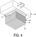
FIG. 4 is a lower perspective view of the heat generation portion and the heat radiation portion. -
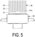
FIG. 5 is a front view of the heat generation portion and the heat radiation portion. -
FIG. 6 is an enlarged view of the heat radiation portion. -
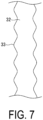
FIG. 7 is an enlarged view of a fin. -
FIG. 8 is an enlarged view of the heat radiation portion. - A vehicular air conditioning device according to an embodiment of the present disclosure will be described below with reference to the accompanying drawings.
- As illustrated in
FIGS. 1 and2 , a vehicular air conditioning device 1 includes acasing 10 that accommodates devices such as afan 41 and an evaporator (not illustrated). - The
casing 10 includes anair inlet 11 and anair outlet 12. - The
casing 10 defines a flow path C communicating with theair inlet 11 and theair outlet 12. - The
air inlet 11 is an opening through which air is taken into thecasing 10 from the outside of thecasing 10. - The
air outlet 12 is an opening through which the air heat-exchanged by the evaporator (not illustrated) is discharged to the outside of thecasing 10. - The flow of air from the
air inlet 11 to theair outlet 12 through the flow path C is generated by thefan 41. - The
fan 41 is housed in thecasing 10 on theair inlet 11 side. - The
fan 41 is rotationally driven by a motor (not illustrated). - The rotation of the motor that drives the
fan 41 is controlled by a power element (for example, a MOS-FET). - The power element is a semiconductor element for power control and generates heat when energized. For this reason, when the vehicular air conditioning device 1 is operated, the power element as a heat generation portion is cooled by a
heat radiation portion 30. - As illustrated in
FIG. 2 , aunit 20 including therein the heat generation portion is attached to awall portion 13 of thecasing 10, thewall portion 13 defining the flow path C. - The
unit 20 is disposed outside the wall portion 13 (outside the casing 10). - As illustrated in
FIGS. 2 to 5 , theheat radiation portion 30 includes abase 31 and a plurality offins 32. - The
heat radiation portion 30 is formed of a metal (for example, an aluminum alloy) having an excellent heat conductivity. - The
base 31 is a portion in thermal contact with the heat generation portion (power element) in theheat radiation portion 30. This enables the heat generated by the heat generation portion to be transferred to theheat radiation portion 30. - The
base 31 is formed with aninstallation surface 31a. - The
installation surface 31a is a surface along the flow direction of air flowing through the flow path C. - In a cross section (see
FIG. 5 ) orthogonal to the flow direction of air, a central portion of theinstallation surface 31a in a width direction protrudes in a convex shape. Note that the protrusion of the central portion is not limited to having a step-like shape as illustrated inFIG. 5 and may have a mountain shape. - The plurality of
fins 32 are provided at theinstallation surface 31a. - Each
fin 32 is a thin plate-like part extending along the flow direction of air and standing from theinstallation surface 31a in a direction orthogonal to the flow direction of air. - As illustrated in
FIG. 2 , theinstallation surface 31a and thefins 32 are disposed in the flow path C (inside the casing 10). - With this configuration, the air flowing through the flow path C takes heat from the
heat radiation portion 30, and consequently the heat generation portion is cooled. - To improve the heat radiation efficiency of the
heat radiation portion 30 configured as described above, the present embodiment adopts the following configuration. - That is, as illustrated in
FIGS. 6 and7 , a plurality ofridges 33 are formed at the side surfaces of thefins 32 which are located along the flow direction of air. - Each
ridge 33 is an elongated protrusion extending along the flow direction of air to be parallel to theinstallation surface 31a. - Each
ridge 33 is formed continuously and integrally along the flow direction of air. Further, the plurality ofridges 33 are provided over the standing direction of the fin 32 (the vertical direction inFIG. 6 ). - By providing the
ridges 33, the surface area of thefins 32 can be increased, and the heat radiation efficiency at theheat radiation portion 30 can be improved. - In addition, it is possible to suppress the air flowing on the
installation surface 31a from being separated from theinstallation surface 31a because the air flowing on theinstallation surface 31a is made less likely to move in the standing direction of thefins 32 by the presence of theridges 33 and the flow velocity of the air is slightly reduced by a flow path resistance generated by theridges 33. In particular, the separation from a rear half portion (a rear half portion in the flow direction of air) of theinstallation surface 31a can be suppressed. - The
ridges 33 may be formed over the entire region of thefins 32 in the height direction of thefins 32. - In that case, the surface area of the
fins 32 can be increased by making the most of the height dimension (the dimension along the standing direction) of thefins 32. - Alternatively, the
ridges 33 may be omitted at a part of aleading end 32a side and a part of abase end 32b side of eachfin 32. - As described above, since the
ridges 33 are portions that can constitute a flow path resistance in view of the entire flow path C, a pressure loss caused by thefins 32 can be reduced by omitting theridges 33 in partial regions in the standing direction. - Alternatively, as illustrated in
FIG. 8 , theridges 33 may be formed only at a half portion of eachfin 32 on thebase end 32b side in the standing direction of thefins 32. - In that case, it is possible to suppress the separation of air on the
base end 32b side of thefins 32 and suppress the pressure loss due to theridges 33 on theleading end 32a side. - The
heat radiation portion 30 configured as described above is made by, for example, extrusion molding. Accordingly, theheat radiation portions 30 having the same cross-sectional shape can be mass-produced. - According to the present embodiment, the following effects are achieved.
- Since the plurality of
ridges 33 formed along the flow direction are provided on the surface of thefins 32 over the standing direction of thefins 32, the surface area of thefins 32 can be increased and the heat radiation efficiency of theheat radiation portion 30 can be improved. - In addition, it is possible to suppress the air flowing on the
installation surface 31a from being separated from theinstallation surface 31a because the air flowing on theinstallation surface 31a is made less likely to move in the standing direction of thefins 32 by the presence of theridges 33 and the flow velocity of the air is slightly reduced by a flow path resistance generated by theridges 33. - Accordingly, the flow of air is maintained on the
installation surface 31a (that is, there is no region where the flow velocity is 0 or where air flows backward), and thus a decrease in the heat radiation efficiency at theinstallation surface 31a and thefins 32 standing from theinstallation surface 31a can be suppressed. - When the
ridges 33 are formed over the entire region of thefins 32 in the standing direction, the surface area of thefins 32 can be maximized. - When the
ridges 33 are not formed at a part of theleading end 32a side and a part of thebase end 32b side of eachfin 32 in the standing direction of thefins 32, the pressure loss in the part of theleading end 32a side and the part of thebase end 32b side can be suppressed. Accordingly, the pressure loss of the entire flow path C can be suppressed. - When the
ridges 33 are formed only at a half portion of eachfin 32 on thebase end 32b side in the standing direction of thefins 32, it is possible to suppress the separation of air on thebase end 32b side and suppress the pressure loss due to theridges 33 on theleading end 32a side. - The present embodiment described above is understood as follows, for example.
- That is, a vehicular air conditioning device according to an aspect of the present disclosure includes: a casing (10) including an air inlet (11) and an air outlet (12), the casing being formed with a flow path (C) communicating with the air inlet and the air outlet; a fan (41) housed in the casing, the fan generating a flow of air from the air inlet to the air outlet through the flow path; a heat generation portion disposed outside the casing; and a heat radiation portion (30). The heat radiation portion includes a base (31) being thermally connected to the heat generation portion and including an installation surface (31a), and a plurality of fins (32) having a plate-like shape. The plurality of fins are disposed in the flow path to extend along a flow direction of the air and stand from the installation surface in a direction orthogonal to the flow direction. The surfaces of the plurality of fins are provided with a plurality of ridges (33). The plurality of ridges are formed along the flow direction and provided along a standing direction of the plurality of fins.
- The vehicular air conditioning device according to the present aspect includes the casing, the fan, the heat generation portion, and the heat radiation portion. The heat radiation portion is thermally connected to the heat generation portion and includes the base including the installation surface, and the plurality of fins having a plate-like shape. The plurality of fins are disposed in the flow path to extend along the flow direction of air and stand from the installation surface in the direction orthogonal to the flow direction. The surfaces of the plurality of fins are provided with the plurality of ridges. The plurality of ridges are formed along the flow direction and provided over the standing direction of the fins. Therefore, the surface area of the fins can be increased, and thus the heat radiation efficiency can be improved.
- In addition, it is possible to suppress the air flowing on the installation surface from being separated from the installation surface because the air flowing on the installation surface is made less likely to move in the standing direction of the fins by the presence of the ridges and the flow velocity of the air is slightly reduced by a flow path resistance generated by the ridges. Accordingly, the flow of air is maintained on the installation surface, and thus a decrease in the heat radiation efficiency at the installation surface and the fins standing from the installation surface can be suppressed.
- Here, the heat generation portion is, for example, a power element that controls the rotation of the fan.
- In the vehicular air conditioning device according to an aspect of the present disclosure, the plurality of ridges are formed over the entire region in the standing direction of the fins.
- In the vehicular air conditioning device according to the present aspect, since the plurality of ridges are formed over the entire region in the standing direction of the fins, the surface area of the fins can be maximized.
- In the vehicular air conditioning device according to an aspect of the present disclosure, the plurality of ridges are not formed at a part of the leading end side and a part of the base end side of each fin in the standing direction of the fins.
- Since the plurality of ridges are not formed at a part of the leading end side and a part of the base end side of each fin in the standing direction of the fins, it is possible to suppress a pressure loss in the part of the leading end side and the part of the base end side. Accordingly, the pressure loss of the entire flow path can be suppressed.
- In the vehicular air conditioning device according to an aspect of the present disclosure, the plurality of ridges are formed only at a half portion of each fin on the base end side in the standing direction of the fins.
- In the vehicular air conditioning device according to the present aspect, since the plurality of ridges are formed only at a half portion of each fin on the base end side in the standing direction of the fins, it is possible to suppress the separation of air on the base end side and suppress the pressure loss due to the ridges on the leading end side.
- In the vehicular air conditioning device according to an aspect of the present disclosure, an extending direction of the plurality of ridges is parallel to the installation surface.
- In the vehicular air conditioning device according to the present aspect, since the extending direction of the plurality of ridges is parallel to the installation surface, the heat radiation portion can be made by extrusion molding.
-
- 1 Vehicular air conditioning device
- 10 Casing
- 11 Air inlet
- 12 Air outlet
- 13 Wall portion
- 20 Unit (unit including a heat generation portion)
- 30 Heat radiation portion
- 31 Base
- 31a Installation surface
- 32 Fin
- 32a Leading end
- 32b Base end
- 33 Ridge
- 41 Fan
Claims (5)
- A vehicular air conditioning device comprising:a casing including an air inlet and an air outlet, the casing being formed with a flow path communicating with the air inlet and the air outlet;a fan housed in the casing, the fan generating a flow of air from the air inlet to the air outlet through the flow path;a heat generation portion disposed outside the casing; anda heat radiation portion,the heat radiation portion includinga base being thermally connected to the heat generation portion and including an installation surface, anda plurality of fins having a plate-like shape, the plurality of fins being disposed in the flow path to extend along a flow direction of the air and stand from the installation surface in a direction orthogonal to the flow direction,wherein surfaces of the plurality of fins are provided with a plurality of ridges, the plurality of ridges being formed along the flow direction and provided along a standing direction of the fins.
- The vehicular air conditioning device according to claim 1, wherein the plurality of ridges are formed over an entire region of the fins in the standing direction of the fins.
- The vehicular air conditioning device according to claim 1, wherein the plurality of ridges are not formed at a part of a leading end side and a part of a base end side of each of the fins in the standing direction of the fins.
- The vehicular air conditioning device according to claim 1, wherein the plurality of ridges are formed only at a half portion of each of the fins on the base end side in the standing direction of the fins.
- The vehicular air conditioning device according to any one of claims 1 to 4, wherein an extending direction of the plurality of ridges is parallel to the installation surface.
Applications Claiming Priority (2)
| Application Number | Priority Date | Filing Date | Title |
|---|---|---|---|
| JP2021111529A JP2023008178A (en) | 2021-07-05 | 2021-07-05 | vehicle air conditioner |
| PCT/JP2022/019780 WO2023281912A1 (en) | 2021-07-05 | 2022-05-10 | Vehicle air-conditioning device |
Publications (2)
| Publication Number | Publication Date |
|---|---|
| EP4349623A1 true EP4349623A1 (en) | 2024-04-10 |
| EP4349623A4 EP4349623A4 (en) | 2024-11-20 |
Family
ID=84801457
Family Applications (1)
| Application Number | Title | Priority Date | Filing Date |
|---|---|---|---|
| EP22837333.8A Withdrawn EP4349623A4 (en) | 2021-07-05 | 2022-05-10 | VEHICLE AIR CONDITIONING |
Country Status (3)
| Country | Link |
|---|---|
| EP (1) | EP4349623A4 (en) |
| JP (1) | JP2023008178A (en) |
| WO (1) | WO2023281912A1 (en) |
Family Cites Families (8)
| Publication number | Priority date | Publication date | Assignee | Title |
|---|---|---|---|---|
| JP3864916B2 (en) * | 2002-08-29 | 2007-01-10 | 株式会社デンソー | Heat exchanger |
| JP2004271168A (en) * | 2003-02-18 | 2004-09-30 | Sanyo Electric Co Ltd | Outdoor machine of air conditioner |
| DE102009037259B4 (en) * | 2009-08-12 | 2012-04-19 | Semikron Elektronik Gmbh & Co. Kg | Arrangement with a cooling device and a power semiconductor module |
| JP2012158247A (en) * | 2011-01-31 | 2012-08-23 | Toyota Motor Corp | Vehicle air-conditioning apparatus |
| CN201986328U (en) * | 2011-03-07 | 2011-09-21 | 上海逸航汽车零部件有限公司 | Heat radiator for automobile air conditioner speed regulation module |
| CN202520596U (en) * | 2012-02-10 | 2012-11-07 | 南京飞洋汽车电子有限责任公司 | Improved automobile air-conditioner blower speed regulating module |
| FR3077771B1 (en) * | 2018-02-09 | 2020-01-17 | Valeo Systemes Thermiques | PULSE CONTROL MODULE AND CORRESPONDING HEATING AND / OR VENTILATION AND / OR AIR CONDITIONING INSTALLATION |
| JP7330745B2 (en) | 2019-04-25 | 2023-08-22 | 三菱重工サーマルシステムズ株式会社 | Vehicle air conditioner |
-
2021
- 2021-07-05 JP JP2021111529A patent/JP2023008178A/en active Pending
-
2022
- 2022-05-10 WO PCT/JP2022/019780 patent/WO2023281912A1/en not_active Ceased
- 2022-05-10 EP EP22837333.8A patent/EP4349623A4/en not_active Withdrawn
Also Published As
| Publication number | Publication date |
|---|---|
| JP2023008178A (en) | 2023-01-19 |
| WO2023281912A1 (en) | 2023-01-12 |
| EP4349623A4 (en) | 2024-11-20 |
Similar Documents
| Publication | Publication Date | Title |
|---|---|---|
| JP4661895B2 (en) | Battery cooling device | |
| US11215107B2 (en) | High voltage cooling fan motor unit | |
| EP2241830A2 (en) | Outdoor unit of air conditioner | |
| JP6818558B2 (en) | Outdoor unit of air conditioner | |
| JP4639648B2 (en) | Inverter device | |
| CN115342445A (en) | Air condensing units and air conditioning equipment | |
| JP2000161717A (en) | Outdoor unit of air conditioner | |
| CN113007885A (en) | Air conditioner | |
| JP4156082B2 (en) | Air conditioner outdoor unit | |
| US11391473B2 (en) | Outdoor unit and air conditioner | |
| US11976827B2 (en) | Outdoor unit and air conditioner | |
| WO2023281912A1 (en) | Vehicle air-conditioning device | |
| CN215637643U (en) | Automatically controlled box, air condensing units and air conditioner | |
| CN106891761A (en) | Charging pile with refrigeration backboard | |
| JP2012164887A (en) | Radiator and heat dissipation system | |
| JP5794866B2 (en) | Air conditioner indoor unit | |
| US11788738B2 (en) | Outdoor unit and air conditioner | |
| PL240268B1 (en) | Outdoor unit for refrigeration cycle device | |
| CN217685393U (en) | Indoor unit of air conditioner | |
| KR102898854B1 (en) | Heating device for vehicle and air conditioner for vehicle having the same | |
| JP2002013836A (en) | Heat exchange equipment | |
| CN222895339U (en) | Heat pump unit | |
| KR100778569B1 (en) | Cooling fan performance booster on the bus | |
| JP2016215866A (en) | Vehicle cooling system | |
| US20240019169A1 (en) | Outdoor unit of airconditioner |
Legal Events
| Date | Code | Title | Description |
|---|---|---|---|
| STAA | Information on the status of an ep patent application or granted ep patent |
Free format text: STATUS: THE INTERNATIONAL PUBLICATION HAS BEEN MADE |
|
| PUAI | Public reference made under article 153(3) epc to a published international application that has entered the european phase |
Free format text: ORIGINAL CODE: 0009012 |
|
| STAA | Information on the status of an ep patent application or granted ep patent |
Free format text: STATUS: REQUEST FOR EXAMINATION WAS MADE |
|
| 17P | Request for examination filed |
Effective date: 20240102 |
|
| AK | Designated contracting states |
Kind code of ref document: A1 Designated state(s): AL AT BE BG CH CY CZ DE DK EE ES FI FR GB GR HR HU IE IS IT LI LT LU LV MC MK MT NL NO PL PT RO RS SE SI SK SM TR |
|
| DAV | Request for validation of the european patent (deleted) | ||
| DAX | Request for extension of the european patent (deleted) | ||
| A4 | Supplementary search report drawn up and despatched |
Effective date: 20241017 |
|
| RIC1 | Information provided on ipc code assigned before grant |
Ipc: H01L 23/467 20060101ALI20241011BHEP Ipc: H01L 23/367 20060101ALI20241011BHEP Ipc: F28F 3/04 20060101ALI20241011BHEP Ipc: H05K 7/20 20060101ALI20241011BHEP Ipc: B60H 1/00 20060101AFI20241011BHEP |
|
| STAA | Information on the status of an ep patent application or granted ep patent |
Free format text: STATUS: THE APPLICATION HAS BEEN WITHDRAWN |
|
| 18W | Application withdrawn |
Effective date: 20250410 |