EP4349569A1 - Manufacturing thermoplastic container with internal baffle(s) - Google Patents
Manufacturing thermoplastic container with internal baffle(s) Download PDFInfo
- Publication number
- EP4349569A1 EP4349569A1 EP23202212.9A EP23202212A EP4349569A1 EP 4349569 A1 EP4349569 A1 EP 4349569A1 EP 23202212 A EP23202212 A EP 23202212A EP 4349569 A1 EP4349569 A1 EP 4349569A1
- Authority
- EP
- European Patent Office
- Prior art keywords
- sidewall
- baffle
- thermoplastic material
- endwall
- mandrel
- Prior art date
- Legal status (The legal status is an assumption and is not a legal conclusion. Google has not performed a legal analysis and makes no representation as to the accuracy of the status listed.)
- Pending
Links
Images



Classifications
-
- B—PERFORMING OPERATIONS; TRANSPORTING
- B29—WORKING OF PLASTICS; WORKING OF SUBSTANCES IN A PLASTIC STATE IN GENERAL
- B29C—SHAPING OR JOINING OF PLASTICS; SHAPING OF MATERIAL IN A PLASTIC STATE, NOT OTHERWISE PROVIDED FOR; AFTER-TREATMENT OF THE SHAPED PRODUCTS, e.g. REPAIRING
- B29C70/00—Shaping composites, i.e. plastics material comprising reinforcements, fillers or preformed parts, e.g. inserts
- B29C70/04—Shaping composites, i.e. plastics material comprising reinforcements, fillers or preformed parts, e.g. inserts comprising reinforcements only, e.g. self-reinforcing plastics
- B29C70/28—Shaping operations therefor
- B29C70/30—Shaping by lay-up, i.e. applying fibres, tape or broadsheet on a mould, former or core; Shaping by spray-up, i.e. spraying of fibres on a mould, former or core
- B29C70/38—Automated lay-up, e.g. using robots, laying filaments according to predetermined patterns
- B29C70/386—Automated tape laying [ATL]
-
- B—PERFORMING OPERATIONS; TRANSPORTING
- B29—WORKING OF PLASTICS; WORKING OF SUBSTANCES IN A PLASTIC STATE IN GENERAL
- B29C—SHAPING OR JOINING OF PLASTICS; SHAPING OF MATERIAL IN A PLASTIC STATE, NOT OTHERWISE PROVIDED FOR; AFTER-TREATMENT OF THE SHAPED PRODUCTS, e.g. REPAIRING
- B29C64/00—Additive manufacturing, i.e. manufacturing of three-dimensional [3D] objects by additive deposition, additive agglomeration or additive layering, e.g. by 3D printing, stereolithography or selective laser sintering
-
- B—PERFORMING OPERATIONS; TRANSPORTING
- B29—WORKING OF PLASTICS; WORKING OF SUBSTANCES IN A PLASTIC STATE IN GENERAL
- B29C—SHAPING OR JOINING OF PLASTICS; SHAPING OF MATERIAL IN A PLASTIC STATE, NOT OTHERWISE PROVIDED FOR; AFTER-TREATMENT OF THE SHAPED PRODUCTS, e.g. REPAIRING
- B29C33/00—Moulds or cores; Details thereof or accessories therefor
- B29C33/44—Moulds or cores; Details thereof or accessories therefor with means for, or specially constructed to facilitate, the removal of articles, e.g. of undercut articles
- B29C33/52—Moulds or cores; Details thereof or accessories therefor with means for, or specially constructed to facilitate, the removal of articles, e.g. of undercut articles soluble or fusible
-
- B—PERFORMING OPERATIONS; TRANSPORTING
- B29—WORKING OF PLASTICS; WORKING OF SUBSTANCES IN A PLASTIC STATE IN GENERAL
- B29C—SHAPING OR JOINING OF PLASTICS; SHAPING OF MATERIAL IN A PLASTIC STATE, NOT OTHERWISE PROVIDED FOR; AFTER-TREATMENT OF THE SHAPED PRODUCTS, e.g. REPAIRING
- B29C53/00—Shaping by bending, folding, twisting, straightening or flattening; Apparatus therefor
- B29C53/56—Winding and joining, e.g. winding spirally
-
- B—PERFORMING OPERATIONS; TRANSPORTING
- B29—WORKING OF PLASTICS; WORKING OF SUBSTANCES IN A PLASTIC STATE IN GENERAL
- B29C—SHAPING OR JOINING OF PLASTICS; SHAPING OF MATERIAL IN A PLASTIC STATE, NOT OTHERWISE PROVIDED FOR; AFTER-TREATMENT OF THE SHAPED PRODUCTS, e.g. REPAIRING
- B29C64/00—Additive manufacturing, i.e. manufacturing of three-dimensional [3D] objects by additive deposition, additive agglomeration or additive layering, e.g. by 3D printing, stereolithography or selective laser sintering
- B29C64/10—Processes of additive manufacturing
- B29C64/165—Processes of additive manufacturing using a combination of solid and fluid materials, e.g. a powder selectively bound by a liquid binder, catalyst, inhibitor or energy absorber
-
- B—PERFORMING OPERATIONS; TRANSPORTING
- B29—WORKING OF PLASTICS; WORKING OF SUBSTANCES IN A PLASTIC STATE IN GENERAL
- B29C—SHAPING OR JOINING OF PLASTICS; SHAPING OF MATERIAL IN A PLASTIC STATE, NOT OTHERWISE PROVIDED FOR; AFTER-TREATMENT OF THE SHAPED PRODUCTS, e.g. REPAIRING
- B29C64/00—Additive manufacturing, i.e. manufacturing of three-dimensional [3D] objects by additive deposition, additive agglomeration or additive layering, e.g. by 3D printing, stereolithography or selective laser sintering
- B29C64/10—Processes of additive manufacturing
- B29C64/188—Processes of additive manufacturing involving additional operations performed on the added layers, e.g. smoothing, grinding or thickness control
-
- B—PERFORMING OPERATIONS; TRANSPORTING
- B29—WORKING OF PLASTICS; WORKING OF SUBSTANCES IN A PLASTIC STATE IN GENERAL
- B29C—SHAPING OR JOINING OF PLASTICS; SHAPING OF MATERIAL IN A PLASTIC STATE, NOT OTHERWISE PROVIDED FOR; AFTER-TREATMENT OF THE SHAPED PRODUCTS, e.g. REPAIRING
- B29C64/00—Additive manufacturing, i.e. manufacturing of three-dimensional [3D] objects by additive deposition, additive agglomeration or additive layering, e.g. by 3D printing, stereolithography or selective laser sintering
- B29C64/20—Apparatus for additive manufacturing; Details thereof or accessories therefor
- B29C64/264—Arrangements for irradiation
- B29C64/268—Arrangements for irradiation using laser beams; using electron beams [EB]
-
- B—PERFORMING OPERATIONS; TRANSPORTING
- B29—WORKING OF PLASTICS; WORKING OF SUBSTANCES IN A PLASTIC STATE IN GENERAL
- B29C—SHAPING OR JOINING OF PLASTICS; SHAPING OF MATERIAL IN A PLASTIC STATE, NOT OTHERWISE PROVIDED FOR; AFTER-TREATMENT OF THE SHAPED PRODUCTS, e.g. REPAIRING
- B29C64/00—Additive manufacturing, i.e. manufacturing of three-dimensional [3D] objects by additive deposition, additive agglomeration or additive layering, e.g. by 3D printing, stereolithography or selective laser sintering
- B29C64/20—Apparatus for additive manufacturing; Details thereof or accessories therefor
- B29C64/295—Heating elements
-
- B—PERFORMING OPERATIONS; TRANSPORTING
- B29—WORKING OF PLASTICS; WORKING OF SUBSTANCES IN A PLASTIC STATE IN GENERAL
- B29C—SHAPING OR JOINING OF PLASTICS; SHAPING OF MATERIAL IN A PLASTIC STATE, NOT OTHERWISE PROVIDED FOR; AFTER-TREATMENT OF THE SHAPED PRODUCTS, e.g. REPAIRING
- B29C64/00—Additive manufacturing, i.e. manufacturing of three-dimensional [3D] objects by additive deposition, additive agglomeration or additive layering, e.g. by 3D printing, stereolithography or selective laser sintering
- B29C64/30—Auxiliary operations or equipment
-
- B—PERFORMING OPERATIONS; TRANSPORTING
- B29—WORKING OF PLASTICS; WORKING OF SUBSTANCES IN A PLASTIC STATE IN GENERAL
- B29C—SHAPING OR JOINING OF PLASTICS; SHAPING OF MATERIAL IN A PLASTIC STATE, NOT OTHERWISE PROVIDED FOR; AFTER-TREATMENT OF THE SHAPED PRODUCTS, e.g. REPAIRING
- B29C64/00—Additive manufacturing, i.e. manufacturing of three-dimensional [3D] objects by additive deposition, additive agglomeration or additive layering, e.g. by 3D printing, stereolithography or selective laser sintering
- B29C64/40—Structures for supporting 3D objects during manufacture and intended to be sacrificed after completion thereof
-
- B—PERFORMING OPERATIONS; TRANSPORTING
- B29—WORKING OF PLASTICS; WORKING OF SUBSTANCES IN A PLASTIC STATE IN GENERAL
- B29C—SHAPING OR JOINING OF PLASTICS; SHAPING OF MATERIAL IN A PLASTIC STATE, NOT OTHERWISE PROVIDED FOR; AFTER-TREATMENT OF THE SHAPED PRODUCTS, e.g. REPAIRING
- B29C70/00—Shaping composites, i.e. plastics material comprising reinforcements, fillers or preformed parts, e.g. inserts
- B29C70/04—Shaping composites, i.e. plastics material comprising reinforcements, fillers or preformed parts, e.g. inserts comprising reinforcements only, e.g. self-reinforcing plastics
- B29C70/28—Shaping operations therefor
- B29C70/30—Shaping by lay-up, i.e. applying fibres, tape or broadsheet on a mould, former or core; Shaping by spray-up, i.e. spraying of fibres on a mould, former or core
- B29C70/38—Automated lay-up, e.g. using robots, laying filaments according to predetermined patterns
-
- B—PERFORMING OPERATIONS; TRANSPORTING
- B29—WORKING OF PLASTICS; WORKING OF SUBSTANCES IN A PLASTIC STATE IN GENERAL
- B29C—SHAPING OR JOINING OF PLASTICS; SHAPING OF MATERIAL IN A PLASTIC STATE, NOT OTHERWISE PROVIDED FOR; AFTER-TREATMENT OF THE SHAPED PRODUCTS, e.g. REPAIRING
- B29C70/00—Shaping composites, i.e. plastics material comprising reinforcements, fillers or preformed parts, e.g. inserts
- B29C70/68—Shaping composites, i.e. plastics material comprising reinforcements, fillers or preformed parts, e.g. inserts by incorporating or moulding on preformed parts, e.g. inserts or layers, e.g. foam blocks
- B29C70/681—Component parts, details or accessories; Auxiliary operations
- B29C70/682—Preformed parts characterised by their structure, e.g. form
-
- B—PERFORMING OPERATIONS; TRANSPORTING
- B29—WORKING OF PLASTICS; WORKING OF SUBSTANCES IN A PLASTIC STATE IN GENERAL
- B29C—SHAPING OR JOINING OF PLASTICS; SHAPING OF MATERIAL IN A PLASTIC STATE, NOT OTHERWISE PROVIDED FOR; AFTER-TREATMENT OF THE SHAPED PRODUCTS, e.g. REPAIRING
- B29C70/00—Shaping composites, i.e. plastics material comprising reinforcements, fillers or preformed parts, e.g. inserts
- B29C70/68—Shaping composites, i.e. plastics material comprising reinforcements, fillers or preformed parts, e.g. inserts by incorporating or moulding on preformed parts, e.g. inserts or layers, e.g. foam blocks
- B29C70/681—Component parts, details or accessories; Auxiliary operations
- B29C70/683—Pretreatment of the preformed part, e.g. insert
-
- B—PERFORMING OPERATIONS; TRANSPORTING
- B29—WORKING OF PLASTICS; WORKING OF SUBSTANCES IN A PLASTIC STATE IN GENERAL
- B29D—PRODUCING PARTICULAR ARTICLES FROM PLASTICS OR FROM SUBSTANCES IN A PLASTIC STATE
- B29D22/00—Producing hollow articles
- B29D22/003—Containers for packaging, storing or transporting, e.g. bottles, jars, cans, barrels, tanks
-
- B—PERFORMING OPERATIONS; TRANSPORTING
- B33—ADDITIVE MANUFACTURING TECHNOLOGY
- B33Y—ADDITIVE MANUFACTURING, i.e. MANUFACTURING OF THREE-DIMENSIONAL [3D] OBJECTS BY ADDITIVE DEPOSITION, ADDITIVE AGGLOMERATION OR ADDITIVE LAYERING, e.g. BY 3D PRINTING, STEREOLITHOGRAPHY OR SELECTIVE LASER SINTERING
- B33Y10/00—Processes of additive manufacturing
-
- B—PERFORMING OPERATIONS; TRANSPORTING
- B33—ADDITIVE MANUFACTURING TECHNOLOGY
- B33Y—ADDITIVE MANUFACTURING, i.e. MANUFACTURING OF THREE-DIMENSIONAL [3D] OBJECTS BY ADDITIVE DEPOSITION, ADDITIVE AGGLOMERATION OR ADDITIVE LAYERING, e.g. BY 3D PRINTING, STEREOLITHOGRAPHY OR SELECTIVE LASER SINTERING
- B33Y70/00—Materials specially adapted for additive manufacturing
- B33Y70/10—Composites of different types of material, e.g. mixtures of ceramics and polymers or mixtures of metals and biomaterials
-
- B—PERFORMING OPERATIONS; TRANSPORTING
- B33—ADDITIVE MANUFACTURING TECHNOLOGY
- B33Y—ADDITIVE MANUFACTURING, i.e. MANUFACTURING OF THREE-DIMENSIONAL [3D] OBJECTS BY ADDITIVE DEPOSITION, ADDITIVE AGGLOMERATION OR ADDITIVE LAYERING, e.g. BY 3D PRINTING, STEREOLITHOGRAPHY OR SELECTIVE LASER SINTERING
- B33Y80/00—Products made by additive manufacturing
-
- B—PERFORMING OPERATIONS; TRANSPORTING
- B60—VEHICLES IN GENERAL
- B60K—ARRANGEMENT OR MOUNTING OF PROPULSION UNITS OR OF TRANSMISSIONS IN VEHICLES; ARRANGEMENT OR MOUNTING OF PLURAL DIVERSE PRIME-MOVERS IN VEHICLES; AUXILIARY DRIVES FOR VEHICLES; INSTRUMENTATION OR DASHBOARDS FOR VEHICLES; ARRANGEMENTS IN CONNECTION WITH COOLING, AIR INTAKE, GAS EXHAUST OR FUEL SUPPLY OF PROPULSION UNITS IN VEHICLES
- B60K15/00—Arrangement in connection with fuel supply of combustion engines or other fuel consuming energy converters, e.g. fuel cells; Mounting or construction of fuel tanks
- B60K15/03—Fuel tanks
- B60K15/03177—Fuel tanks made of non-metallic material, e.g. plastics, or of a combination of non-metallic and metallic material
-
- F—MECHANICAL ENGINEERING; LIGHTING; HEATING; WEAPONS; BLASTING
- F17—STORING OR DISTRIBUTING GASES OR LIQUIDS
- F17C—VESSELS FOR CONTAINING OR STORING COMPRESSED, LIQUEFIED OR SOLIDIFIED GASES; FIXED-CAPACITY GAS-HOLDERS; FILLING VESSELS WITH, OR DISCHARGING FROM VESSELS, COMPRESSED, LIQUEFIED, OR SOLIDIFIED GASES
- F17C1/00—Pressure vessels, e.g. gas cylinder, gas tank, replaceable cartridge
- F17C1/16—Pressure vessels, e.g. gas cylinder, gas tank, replaceable cartridge constructed of plastics materials
-
- B—PERFORMING OPERATIONS; TRANSPORTING
- B29—WORKING OF PLASTICS; WORKING OF SUBSTANCES IN A PLASTIC STATE IN GENERAL
- B29L—INDEXING SCHEME ASSOCIATED WITH SUBCLASS B29C, RELATING TO PARTICULAR ARTICLES
- B29L2031/00—Other particular articles
- B29L2031/712—Containers; Packaging elements or accessories, Packages
- B29L2031/7172—Fuel tanks, jerry cans
-
- B—PERFORMING OPERATIONS; TRANSPORTING
- B33—ADDITIVE MANUFACTURING TECHNOLOGY
- B33Y—ADDITIVE MANUFACTURING, i.e. MANUFACTURING OF THREE-DIMENSIONAL [3D] OBJECTS BY ADDITIVE DEPOSITION, ADDITIVE AGGLOMERATION OR ADDITIVE LAYERING, e.g. BY 3D PRINTING, STEREOLITHOGRAPHY OR SELECTIVE LASER SINTERING
- B33Y30/00—Apparatus for additive manufacturing; Details thereof or accessories therefor
-
- B—PERFORMING OPERATIONS; TRANSPORTING
- B60—VEHICLES IN GENERAL
- B60K—ARRANGEMENT OR MOUNTING OF PROPULSION UNITS OR OF TRANSMISSIONS IN VEHICLES; ARRANGEMENT OR MOUNTING OF PLURAL DIVERSE PRIME-MOVERS IN VEHICLES; AUXILIARY DRIVES FOR VEHICLES; INSTRUMENTATION OR DASHBOARDS FOR VEHICLES; ARRANGEMENTS IN CONNECTION WITH COOLING, AIR INTAKE, GAS EXHAUST OR FUEL SUPPLY OF PROPULSION UNITS IN VEHICLES
- B60K15/00—Arrangement in connection with fuel supply of combustion engines or other fuel consuming energy converters, e.g. fuel cells; Mounting or construction of fuel tanks
- B60K15/03—Fuel tanks
- B60K2015/03032—Manufacturing of fuel tanks
-
- B—PERFORMING OPERATIONS; TRANSPORTING
- B60—VEHICLES IN GENERAL
- B60K—ARRANGEMENT OR MOUNTING OF PROPULSION UNITS OR OF TRANSMISSIONS IN VEHICLES; ARRANGEMENT OR MOUNTING OF PLURAL DIVERSE PRIME-MOVERS IN VEHICLES; AUXILIARY DRIVES FOR VEHICLES; INSTRUMENTATION OR DASHBOARDS FOR VEHICLES; ARRANGEMENTS IN CONNECTION WITH COOLING, AIR INTAKE, GAS EXHAUST OR FUEL SUPPLY OF PROPULSION UNITS IN VEHICLES
- B60K15/00—Arrangement in connection with fuel supply of combustion engines or other fuel consuming energy converters, e.g. fuel cells; Mounting or construction of fuel tanks
- B60K15/03—Fuel tanks
- B60K15/077—Fuel tanks with means modifying or controlling distribution or motion of fuel, e.g. to prevent noise, surge, splash or fuel starvation
- B60K2015/0777—Fuel tanks with means modifying or controlling distribution or motion of fuel, e.g. to prevent noise, surge, splash or fuel starvation in-tank reservoirs or baffles integrally manufactured with the fuel Tank
-
- F—MECHANICAL ENGINEERING; LIGHTING; HEATING; WEAPONS; BLASTING
- F17—STORING OR DISTRIBUTING GASES OR LIQUIDS
- F17C—VESSELS FOR CONTAINING OR STORING COMPRESSED, LIQUEFIED OR SOLIDIFIED GASES; FIXED-CAPACITY GAS-HOLDERS; FILLING VESSELS WITH, OR DISCHARGING FROM VESSELS, COMPRESSED, LIQUEFIED, OR SOLIDIFIED GASES
- F17C2201/00—Vessel construction, in particular geometry, arrangement or size
- F17C2201/01—Shape
- F17C2201/0104—Shape cylindrical
- F17C2201/0109—Shape cylindrical with exteriorly curved end-piece
-
- F—MECHANICAL ENGINEERING; LIGHTING; HEATING; WEAPONS; BLASTING
- F17—STORING OR DISTRIBUTING GASES OR LIQUIDS
- F17C—VESSELS FOR CONTAINING OR STORING COMPRESSED, LIQUEFIED OR SOLIDIFIED GASES; FIXED-CAPACITY GAS-HOLDERS; FILLING VESSELS WITH, OR DISCHARGING FROM VESSELS, COMPRESSED, LIQUEFIED, OR SOLIDIFIED GASES
- F17C2201/00—Vessel construction, in particular geometry, arrangement or size
- F17C2201/05—Size
- F17C2201/054—Size medium (>1 m3)
-
- F—MECHANICAL ENGINEERING; LIGHTING; HEATING; WEAPONS; BLASTING
- F17—STORING OR DISTRIBUTING GASES OR LIQUIDS
- F17C—VESSELS FOR CONTAINING OR STORING COMPRESSED, LIQUEFIED OR SOLIDIFIED GASES; FIXED-CAPACITY GAS-HOLDERS; FILLING VESSELS WITH, OR DISCHARGING FROM VESSELS, COMPRESSED, LIQUEFIED, OR SOLIDIFIED GASES
- F17C2201/00—Vessel construction, in particular geometry, arrangement or size
- F17C2201/05—Size
- F17C2201/056—Small (<1 m3)
-
- F—MECHANICAL ENGINEERING; LIGHTING; HEATING; WEAPONS; BLASTING
- F17—STORING OR DISTRIBUTING GASES OR LIQUIDS
- F17C—VESSELS FOR CONTAINING OR STORING COMPRESSED, LIQUEFIED OR SOLIDIFIED GASES; FIXED-CAPACITY GAS-HOLDERS; FILLING VESSELS WITH, OR DISCHARGING FROM VESSELS, COMPRESSED, LIQUEFIED, OR SOLIDIFIED GASES
- F17C2203/00—Vessel construction, in particular walls or details thereof
- F17C2203/06—Materials for walls or layers thereof; Properties or structures of walls or their materials
- F17C2203/0602—Wall structures; Special features thereof
- F17C2203/0612—Wall structures
- F17C2203/0614—Single wall
- F17C2203/0617—Single wall with one layer
-
- F—MECHANICAL ENGINEERING; LIGHTING; HEATING; WEAPONS; BLASTING
- F17—STORING OR DISTRIBUTING GASES OR LIQUIDS
- F17C—VESSELS FOR CONTAINING OR STORING COMPRESSED, LIQUEFIED OR SOLIDIFIED GASES; FIXED-CAPACITY GAS-HOLDERS; FILLING VESSELS WITH, OR DISCHARGING FROM VESSELS, COMPRESSED, LIQUEFIED, OR SOLIDIFIED GASES
- F17C2203/00—Vessel construction, in particular walls or details thereof
- F17C2203/06—Materials for walls or layers thereof; Properties or structures of walls or their materials
- F17C2203/0634—Materials for walls or layers thereof
- F17C2203/0658—Synthetics
- F17C2203/066—Plastics
-
- F—MECHANICAL ENGINEERING; LIGHTING; HEATING; WEAPONS; BLASTING
- F17—STORING OR DISTRIBUTING GASES OR LIQUIDS
- F17C—VESSELS FOR CONTAINING OR STORING COMPRESSED, LIQUEFIED OR SOLIDIFIED GASES; FIXED-CAPACITY GAS-HOLDERS; FILLING VESSELS WITH, OR DISCHARGING FROM VESSELS, COMPRESSED, LIQUEFIED, OR SOLIDIFIED GASES
- F17C2221/00—Handled fluid, in particular type of fluid
- F17C2221/01—Pure fluids
- F17C2221/012—Hydrogen
-
- F—MECHANICAL ENGINEERING; LIGHTING; HEATING; WEAPONS; BLASTING
- F17—STORING OR DISTRIBUTING GASES OR LIQUIDS
- F17C—VESSELS FOR CONTAINING OR STORING COMPRESSED, LIQUEFIED OR SOLIDIFIED GASES; FIXED-CAPACITY GAS-HOLDERS; FILLING VESSELS WITH, OR DISCHARGING FROM VESSELS, COMPRESSED, LIQUEFIED, OR SOLIDIFIED GASES
- F17C2223/00—Handled fluid before transfer, i.e. state of fluid when stored in the vessel or before transfer from the vessel
- F17C2223/01—Handled fluid before transfer, i.e. state of fluid when stored in the vessel or before transfer from the vessel characterised by the phase
- F17C2223/0146—Two-phase
- F17C2223/0153—Liquefied gas, e.g. LPG, GPL
- F17C2223/0161—Liquefied gas, e.g. LPG, GPL cryogenic, e.g. LNG, GNL, PLNG
-
- F—MECHANICAL ENGINEERING; LIGHTING; HEATING; WEAPONS; BLASTING
- F17—STORING OR DISTRIBUTING GASES OR LIQUIDS
- F17C—VESSELS FOR CONTAINING OR STORING COMPRESSED, LIQUEFIED OR SOLIDIFIED GASES; FIXED-CAPACITY GAS-HOLDERS; FILLING VESSELS WITH, OR DISCHARGING FROM VESSELS, COMPRESSED, LIQUEFIED, OR SOLIDIFIED GASES
- F17C2223/00—Handled fluid before transfer, i.e. state of fluid when stored in the vessel or before transfer from the vessel
- F17C2223/03—Handled fluid before transfer, i.e. state of fluid when stored in the vessel or before transfer from the vessel characterised by the pressure level
- F17C2223/033—Small pressure, e.g. for liquefied gas
-
- F—MECHANICAL ENGINEERING; LIGHTING; HEATING; WEAPONS; BLASTING
- F17—STORING OR DISTRIBUTING GASES OR LIQUIDS
- F17C—VESSELS FOR CONTAINING OR STORING COMPRESSED, LIQUEFIED OR SOLIDIFIED GASES; FIXED-CAPACITY GAS-HOLDERS; FILLING VESSELS WITH, OR DISCHARGING FROM VESSELS, COMPRESSED, LIQUEFIED, OR SOLIDIFIED GASES
- F17C2260/00—Purposes of gas storage and gas handling
- F17C2260/01—Improving mechanical properties or manufacturing
- F17C2260/016—Preventing slosh
-
- F—MECHANICAL ENGINEERING; LIGHTING; HEATING; WEAPONS; BLASTING
- F17—STORING OR DISTRIBUTING GASES OR LIQUIDS
- F17C—VESSELS FOR CONTAINING OR STORING COMPRESSED, LIQUEFIED OR SOLIDIFIED GASES; FIXED-CAPACITY GAS-HOLDERS; FILLING VESSELS WITH, OR DISCHARGING FROM VESSELS, COMPRESSED, LIQUEFIED, OR SOLIDIFIED GASES
- F17C2270/00—Applications
- F17C2270/01—Applications for fluid transport or storage
- F17C2270/0186—Applications for fluid transport or storage in the air or in space
-
- F—MECHANICAL ENGINEERING; LIGHTING; HEATING; WEAPONS; BLASTING
- F17—STORING OR DISTRIBUTING GASES OR LIQUIDS
- F17C—VESSELS FOR CONTAINING OR STORING COMPRESSED, LIQUEFIED OR SOLIDIFIED GASES; FIXED-CAPACITY GAS-HOLDERS; FILLING VESSELS WITH, OR DISCHARGING FROM VESSELS, COMPRESSED, LIQUEFIED, OR SOLIDIFIED GASES
- F17C2270/00—Applications
- F17C2270/01—Applications for fluid transport or storage
- F17C2270/0186—Applications for fluid transport or storage in the air or in space
- F17C2270/0189—Planes
Definitions
- This disclosure relates generally to thermoplastics and, more particularly, to manufacturing a thermoplastic container.
- An apparatus such as an aircraft may include a thermoplastic container to hold a fluid.
- thermoplastic containers Various types and configurations of thermoplastic containers are known in the art.
- various methods for manufacturing thermoplastic containers are known in the art.
- various methods are also known in the art for manufacturing thermoplastic articles including using a laser assisted, in-situ fiber placement device to form a thermoplastic skin over a structural thermoplastic frame. While these known manufacturing methods have various advantages, there is still room in the art for improvement. There is a need in the art, in particular, for methods which can further automate and/or simplify manufacture of a thermoplastic container.
- a method for manufacturing a container.
- a baffle is provided.
- the baffle is configured from or otherwise includes baffle thermoplastic material.
- a sidewall is formed using an additive manufacturing device. The sidewall is bonded to the baffle during the forming of the sidewall. The sidewall circumscribes the baffle.
- the sidewall is configured from or otherwise includes sidewall thermoplastic material.
- the container includes an internal chamber, the baffle and the sidewall. The sidewall forms an outer peripheral boundary of the internal chamber. The baffle is arranged within the internal chamber.
- a method for manufacturing a fuel reservoir.
- baffle thermoplastic material is stamp formed to form a baffle of the fuel reservoir.
- Fiber-reinforced thermoplastic material is wrapped around the baffle using an in-situ fiber placement device to form a sidewall of the fuel reservoir.
- the fiber-reinforced thermoplastic material includes fiber reinforcement within sidewall thermoplastic material.
- the sidewall thermoplastic material is heated as the fiber-reinforced thermoplastic material is being wrapped to bond the sidewall thermoplastic material to the baffle thermoplastic material.
- a baffle of the fuel reservoir is provided.
- the baffle is configured from or otherwise includes baffle thermoplastic material.
- a mandrel is provided.
- the baffle is arranged with and supported by the mandrel.
- Fiber-reinforced thermoplastic material is wrapped around the mandrel and the baffle using an in-situ fiber placement device to form a sidewall of the fuel reservoir.
- the fiber-reinforced thermoplastic material includes fiber reinforcement within sidewall thermoplastic material.
- the sidewall thermoplastic material is heated as the fiber-reinforced thermoplastic material is being wrapped to bond the sidewall thermoplastic material to the baffle thermoplastic material.
- the additive manufacturing device may be configured as or otherwise include a laser assisted, in-situ fiber placement device.
- the forming of the sidewall may include placing and heating fiber-reinforced thermoplastic material using the additive manufacturing device.
- the fiber-reinforced thermoplastic material may include fiber reinforcement embedded within the sidewall thermoplastic material.
- the fiber-reinforced thermoplastic material may be heated using a laser.
- the method may also include providing a mandrel.
- the baffle may be disposed with the mandrel prior to the forming of the sidewall.
- the mandrel may support the sidewall thermoplastic material during the forming of the sidewall.
- the mandrel may locate the baffle during the forming of the sidewall.
- the forming of the sidewall may include: wrapping fiber-reinforced thermoplastic material around the mandrel and the baffle, the fiber-reinforced thermoplastic material including fiber reinforcement embedded within the sidewall thermoplastic material; and heating the fiber-reinforced thermoplastic material to form the sidewall and bond the sidewall thermoplastic material to the baffle thermoplastic material.
- the method may also include removing the mandrel from within an internal bore of the sidewall following the forming of the sidewall.
- the removing of the mandrel may include mechanically collapsing the mandrel.
- the removing of the mandrel may include decomposing the mandrel.
- the container may also include an endwall connected to the sidewall.
- the mandrel may be removed through an aperture in the endwall.
- the method may also include bonding an endwall to the sidewall following the removing of the mandrel.
- the container may also include the endwall.
- the method may also include integrally forming an endwall with the sidewall using the additive manufacturing device.
- the container may include the endwall.
- the endwall may form a side peripheral boundary of the internal chamber.
- the method may also include: providing an endwall; and bonding the endwall to the sidewall following the forming of the sidewall.
- the container may include the endwall.
- the endwall may form a side peripheral boundary of the internal chamber.
- the providing of the endwall may include stamp forming the endwall.
- the providing of the baffle may include stamp forming the baffle.
- the container may be configured as a fuel reservoir for an aircraft.
- the baffle may divide the internal chamber into a plurality of fluidly coupled sub-chambers.
- the baffle may have a percentage of open area across the internal chamber that is less than fifty percent.
- the present disclosure may include any one or more of the individual features disclosed above and/or below alone or in any combination thereof.
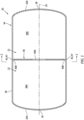
- FIGS. 1 and 2 illustrate a thermoplastic container 20 with an internal chamber 22 such as a sealed, fluid tight internal cavity.
- the container 20 may be a fuel reservoir for an apparatus such as an aircraft; e.g., an airplane, a helicopter or a drone.
- the container 20, for example, may be configured to store hydrocarbon fuel (e.g., jet fuel) or non-hydrocarbon fuel (e.g., liquid hydrogen) within its internal chamber 22 for subsequent use in a powerplant of the aircraft.
- the aircraft powerplant may be configured as part of a propulsion system for the aircraft and/or an electrical power generation system for the aircraft.
- the container 20 of the present disclosure is not limited to aircraft applications nor to storing fuel for a powerplant.
- the container 20, may alternatively be configured for storing potable water, wastewater, lubricant, coolant and/or any other fluid in liquid and/or gaseous form.
- the container 20 may be described below as the fuel reservoir for the aircraft powerplant.
- the container 20 of FIG. 1 extends longitudinally along a longitudinal centerline 24 of the container 20 between a first end 26 of the container 20 and a second end 28 of the container 20.
- the container 20 includes a (e.g., cylindrical) container sidewall 30 and one or more (e.g., partially hemispherical) container endwalls 32A and 32B (generally referred to as "32").
- the sidewall 30 extends longitudinally along the longitudinal centerline 24 between and to the first endwall 32A and the second endwall 32B. This sidewall 30 may be formed integral with the first endwall 32A and/or the second endwall 32B.
- the sidewall 30 may be formed discrete from and then subsequently connected (e.g., welded or otherwise bonded) to the first endwall 32A and/or the second endwall 32B.
- the first endwall 32A is located at (e.g., on, adjacent or proximate) the container first end 26.
- the second endwall 32B is located at the container second end 28.
- the sidewall 30, the first endwall 32A and the second endwall 32B of FIGS. 1 and 2 may collectively form an exterior shell 34 (e.g., casing) of the container 20 that surrounds and forms boundaries of the internal chamber 22.
- the sidewall 30, for example, extends circumferentially about the longitudinal centerline 24 and the internal chamber 22 and forms a radial outer peripheral boundary of the internal chamber 22.
- the first endwall 32A encloses the container first end 26 and forms a longitudinal end peripheral boundary of the internal chamber 22 at the container first end 26.
- the second endwall 32B encloses the container second end 28 and forms a longitudinal end peripheral boundary of the internal chamber 22 at the container second end 28.
- the container 20 of FIGS. 1 and 2 includes at least (or only) one internal baffle 36.
- This baffle 36 is arranged within the internal chamber 22.
- the baffle 36 may divide the internal chamber 22 into a plurality of sub-chambers 38A and 38B (generally referred to as "38"); e.g., fluidly coupled sub-cavities, zones, etc.
- the baffle 36 of FIGS. 1 and 2 for example, extends laterally across the internal chamber 22 to opposing (e.g., diametric) sides of the exterior shell 34.
- the baffle 36 may extend radially out (e.g., in all direction along a reference plane offset (e.g., perpendicular) to the longitudinal centerline 24) towards or to the sidewall 30.
- the baffle 36 is also welded or otherwise bonded to the exterior shell 34 and its sidewall 30.
- the baffle 36 of FIGS. 1 and 2 includes one or more apertures 40A and 40B (generally referred to as "40"); e.g., windows, ports, through-holes, notches, grooves, etc. These apertures 40 fluidly couple the sub-chambers 38 together on opposing longitudinal sides of the baffle 36.
- the apertures 40 collectively provide the baffle 36 with a percentage of open area (POA) across the internal chamber 22. This percentage of open area may be less than fifty percent (50%); e.g., less than forty percent (40%), thirty percent (30%), twenty percent (20%), etc.
- apertures 40 in the baffle 36 fluidly couple the sub-chambers 38 together and may permit flow of the fluid across the baffle 36
- material of the baffle 36 may reduce shifting, swashing and/or other (e.g., undesirable, unintended, etc.) movement of fluid within the internal chamber 22.
- the present disclosure is not limited to the foregoing exemplary percentage of open area.
- At least one of the apertures may be disposed in a central region of the baffle 36.
- one or more of the apertures may be disposed along an outer edge 42 of the baffle 36; e.g., between the baffle 36 and the sidewall 30.
- various baffle aperture arrangements are known in the art, and the present disclosure is not limited to any particular ones thereof.
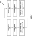
- FIG. 3 is a flow diagram of a method 300 for manufacturing a thermoplastic container.
- the manufacturing method 300 is described below with reference to the container 20 of FIGS. 1 and 2 .
- the manufacturing method 300 may alternatively manufacture various other container types and configurations.
- the baffle 36 is provided.
- Baffle thermoplastic material may be stamp formed to provide the baffle 36.
- the baffle thermoplastic material more particularly, may be heated and pressed between a set of dies to form the baffle 36.
- the baffle thermoplastic material include, but are not limited to polyether ether ketone (PEEK), polyaryletherketone (PAEK), polyetherketoneketone (PEKK) and polyphenylene sulfide (PPS).
- the baffle 36 may be formed substantially (or only) from the baffle thermoplastic material.
- the baffle 36 may also be formed with fiber reinforcement embedded within the baffle thermoplastic material; here, the baffle thermoplastic material provides a matrix for the fiber reinforcement.
- the fiber reinforcement include, but are not limited to, fiberglass fibers, carbon fibers and/or aramid (e.g., Kevlar ® ) fibers.
- a mandrel 44 is provided.
- the baffle 36 is disposed with the mandrel 44, and may be supported, located and/or orientated by the mandrel 44 during one or more subsequent step(s) of the manufacturing method 300.
- the baffle 36 of FIG. 5 for example, is arranged between two end sections 46A and 46B (generally referred to as "46") of the mandrel 44.
- a peripheral surface 47 (or surfaces) of the baffle 36 at the outer edge 42 may be radially aligned with (e.g., flush with), or may be slightly recessed in from or protrude out from, an adjacent exterior surface 48A, 48B of each mandrel end section 46A, 46B.
- An intermediate section 50 of the mandrel 44 may extend through at least one of the baffle apertures 40 (e.g., the central baffle aperture 40A) between and may connect the mandrel end sections 46.
- the sidewall 30 is formed using an additive manufacturing device 52 such as a laser assisted, in-situ fiber placement device.
- Fiber-reinforced thermoplastic material e.g., fiber-reinforced thermoplastic tape
- the fiber-reinforcement thermoplastic material may be wrapped around the mandrel end sections 46 as well as the baffle 36.
- the fiber-reinforced thermoplastic material is (e.g., locally) heated using a laser or another heat source of the additive manufacturing device 52.
- This heating may facilitate (e.g., permanent) conformation of the fiber-reinforced thermoplastic material to the geometry of the mandrel end sections 46.
- the heating of the fiber-reinforced thermoplastic material may also bond (e.g., weld) the fiber-reinforced thermoplastic material being placed to (1) the baffle 36 upon placement of that fiber-reinforced thermoplastic material on the baffle 36 and (2) previously placed fiber-reinforced thermoplastic material upon placement thereon.
- the sidewall 30 may thereby be formed as a multi-layered structure that is bonded (e.g., welded) to the baffle 36 in a single formation step.
- the fiber-reinforced thermoplastic material may include fiber reinforcement embedded within sidewall thermoplastic material.
- the fiber reinforcement include, but are not limited to, fiberglass fibers, carbon fibers and/or aramid (e.g., Kevlar ® ) fibers.
- the sidewall thermoplastic material include, but are not limited to, polyether ether ketone (PEEK), polyaryletherketone (PAEK), polyetherketoneketone (PEKK) and polyphenylene sulfide (PPS). This sidewall thermoplastic material may be the same as the baffle thermoplastic material.
- the sidewall 30 and the baffle 36 may be formed from different types of thermoplastic material - the sidewall thermoplastic material may different than the baffle thermoplastic material where, for example, the processes allow for melt temperature and adequate intermingling of polymer chains between the sidewall and baffle to be "welded".
- the sidewall thermoplastic material is bonded to the baffle thermoplastic material.
- a portion of the sidewall thermoplastic material is bonded to a portion of the sidewall thermoplastic material.
- the mandrel 44 is removed from an internal bore of the sidewall 30.
- the mandrel 44 may be mechanically collapsed.
- the mandrel 44 is configured as a mechanically expandable / collapsible mandrel.
- the mandrel 44 may be mechanically (e.g., via vibrations) and/or chemically decomposed.
- the mandrel 44 is configured as an expendable mandrel, a washout mandrel, etc.
- the present disclosure is not limited to the foregoing exemplary mandrel types or removal techniques.
- each endwall 32 is provided.
- Endwall thermoplastic material may be stamp formed to provide the respective endwall 32.
- the endwall thermoplastic material more particularly, may be heated and pressed between a set of dies to form the respective endwall 32.
- the endwall thermoplastic material include, but are not limited to, polyether ether ketone (PEEK), polyaryletherketone (PAEK), polyetherketoneketone (PEKK) and polyphenylene sulfide (PPS).
- PEEK polyether ether ketone
- PAEK polyaryletherketone
- PEKK polyetherketoneketone
- PPS polyphenylene sulfide
- the respective endwall 32 may be formed substantially (or only) from the endwall thermoplastic material.
- the respective endwall 32 may also be formed with fiber reinforcement embedded within the endwall thermoplastic material; here, the endwall thermoplastic material provides a matrix for the fiber reinforcement.
- the fiber reinforcement include, but are not limited to, fiberglass fibers, carbon fibers and/or aramid (e.g., Kevlar ® ) fibers.
- each endwall 32 is connected to the sidewall 30 to form the container 20.
- Each endwall 32 may be bonded to the sidewall 30 using the laser or another device part of or discrete from the additive manufacturing device 52.
- the manufacturing method 300 may be performed such that the mandrel 44 is removed prior to formation of the endwall(s) 32 and/or connection of the endwall(s) 32 to the sidewall 30. In other embodiments, the manufacturing method 300 may be performed such that the mandrel 44 is removed subsequent to the formation of the endwall(s) 32 and connection of the endwall(s) 32 to the sidewall 30. In such embodiments, the mandrel 44 and its respective mandrel end section(s) 46 may support the endwall(s) 32 during formation and/or connection of the endwall(s) 32 to the sidewall 30. This may also facilitate forming one or more of the endwalls 32 integrally with the sidewall 30.
- the fiber-reinforced thermoplastic material may be placed with the mandrel 44 and the baffle 36 using the additive manufacturing device 52 to form the sidewall 30 and the endwall(s) 32.
- the mandrel 44 may be removed from an aperture 54 in at least one of the endwalls 32 (e.g., see FIG. 10 ) to provide an empty internal chamber 22.
- the container 20 may include a single baffle 36 within the internal chamber 22. In other embodiments, referring to FIG. 11 , the container 20 may include multiple of the baffles 36 within the internal chamber 22. Such a multi-baffle container 20 may be manufactured similarly using the manufacturing method 300.
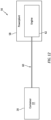
- FIG. 12 schematically illustrates a system 56 for an aircraft.
- This aircraft system 56 includes the container 20.
- the aircraft system 56 also includes an aircraft powerplant 58 and a fuel circuit 60 for delivering fuel stored within the internal chamber 22 of the container 20 to the aircraft powerplant 58.
- the aircraft powerplant 58 includes an engine 62.
- This engine 62 may be configured as or otherwise include a gas turbine engine or another type of engine such as, but not limited to, a reciprocating piston engine, a rotary engine, etc.
Landscapes
- Engineering & Computer Science (AREA)
- Chemical & Material Sciences (AREA)
- Mechanical Engineering (AREA)
- Materials Engineering (AREA)
- Manufacturing & Machinery (AREA)
- Physics & Mathematics (AREA)
- Optics & Photonics (AREA)
- Composite Materials (AREA)
- Robotics (AREA)
- Toxicology (AREA)
- Health & Medical Sciences (AREA)
- Plasma & Fusion (AREA)
- Life Sciences & Earth Sciences (AREA)
- Sustainable Development (AREA)
- Sustainable Energy (AREA)
- Combustion & Propulsion (AREA)
- Transportation (AREA)
- General Engineering & Computer Science (AREA)
- Ceramic Engineering (AREA)
- Civil Engineering (AREA)
- Structural Engineering (AREA)
Abstract
Description
- This disclosure relates generally to thermoplastics and, more particularly, to manufacturing a thermoplastic container.
- An apparatus such as an aircraft may include a thermoplastic container to hold a fluid. Various types and configurations of thermoplastic containers are known in the art. Furthermore, various methods for manufacturing thermoplastic containers are known in the art. More generally, various methods are also known in the art for manufacturing thermoplastic articles including using a laser assisted, in-situ fiber placement device to form a thermoplastic skin over a structural thermoplastic frame. While these known manufacturing methods have various advantages, there is still room in the art for improvement. There is a need in the art, in particular, for methods which can further automate and/or simplify manufacture of a thermoplastic container.
- According to an aspect of the present disclosure, a method is provided for manufacturing a container. During this method, a baffle is provided. The baffle is configured from or otherwise includes baffle thermoplastic material. A sidewall is formed using an additive manufacturing device. The sidewall is bonded to the baffle during the forming of the sidewall. The sidewall circumscribes the baffle. The sidewall is configured from or otherwise includes sidewall thermoplastic material. The container includes an internal chamber, the baffle and the sidewall. The sidewall forms an outer peripheral boundary of the internal chamber. The baffle is arranged within the internal chamber.
- According to another aspect of the present disclosure, which the Applicant expressly reserved the right to claim independently, a method is provided for manufacturing a fuel reservoir. During this method, baffle thermoplastic material is stamp formed to form a baffle of the fuel reservoir. Fiber-reinforced thermoplastic material is wrapped around the baffle using an in-situ fiber placement device to form a sidewall of the fuel reservoir. The fiber-reinforced thermoplastic material includes fiber reinforcement within sidewall thermoplastic material. The sidewall thermoplastic material is heated as the fiber-reinforced thermoplastic material is being wrapped to bond the sidewall thermoplastic material to the baffle thermoplastic material.
- According to still another aspect of the present disclosure, which the Applicant also expressly reserves the right to claim independently, another method is provided for manufacturing a fuel reservoir. During this method, a baffle of the fuel reservoir is provided. The baffle is configured from or otherwise includes baffle thermoplastic material. A mandrel is provided. The baffle is arranged with and supported by the mandrel. Fiber-reinforced thermoplastic material is wrapped around the mandrel and the baffle using an in-situ fiber placement device to form a sidewall of the fuel reservoir. The fiber-reinforced thermoplastic material includes fiber reinforcement within sidewall thermoplastic material. The sidewall thermoplastic material is heated as the fiber-reinforced thermoplastic material is being wrapped to bond the sidewall thermoplastic material to the baffle thermoplastic material.
- The additive manufacturing device may be configured as or otherwise include a laser assisted, in-situ fiber placement device.
- The forming of the sidewall may include placing and heating fiber-reinforced thermoplastic material using the additive manufacturing device. The fiber-reinforced thermoplastic material may include fiber reinforcement embedded within the sidewall thermoplastic material.
- The fiber-reinforced thermoplastic material may be heated using a laser.
- The method may also include providing a mandrel. The baffle may be disposed with the mandrel prior to the forming of the sidewall. The mandrel may support the sidewall thermoplastic material during the forming of the sidewall.
- The mandrel may locate the baffle during the forming of the sidewall.
- The forming of the sidewall may include: wrapping fiber-reinforced thermoplastic material around the mandrel and the baffle, the fiber-reinforced thermoplastic material including fiber reinforcement embedded within the sidewall thermoplastic material; and heating the fiber-reinforced thermoplastic material to form the sidewall and bond the sidewall thermoplastic material to the baffle thermoplastic material.
- The method may also include removing the mandrel from within an internal bore of the sidewall following the forming of the sidewall.
- The removing of the mandrel may include mechanically collapsing the mandrel.
- The removing of the mandrel may include decomposing the mandrel.
- The container may also include an endwall connected to the sidewall. The mandrel may be removed through an aperture in the endwall.
- The method may also include bonding an endwall to the sidewall following the removing of the mandrel. The container may also include the endwall.
- The method may also include integrally forming an endwall with the sidewall using the additive manufacturing device. The container may include the endwall. The endwall may form a side peripheral boundary of the internal chamber.
- The method may also include: providing an endwall; and bonding the endwall to the sidewall following the forming of the sidewall. The container may include the endwall. The endwall may form a side peripheral boundary of the internal chamber.
- The providing of the endwall may include stamp forming the endwall.
- The providing of the baffle may include stamp forming the baffle.
- The container may be configured as a fuel reservoir for an aircraft.
- The baffle may divide the internal chamber into a plurality of fluidly coupled sub-chambers. The baffle may have a percentage of open area across the internal chamber that is less than fifty percent.
- The present disclosure may include any one or more of the individual features disclosed above and/or below alone or in any combination thereof.
- The foregoing features and the operation of the invention will become more apparent in light of the following description and the accompanying drawings.
-
-
FIG. 1 is a side sectional illustration of a thermoplastic container with an internal baffle. -
FIG. 2 is a cross-sectional illustration of the thermoplastic container taken along line 2-2 inFIG. 1 . -
FIG. 3 is a flow diagram of a method for manufacturing a thermoplastic container. -
FIG. 4 is a side sectional illustration of the baffle. -
FIG. 5 is a side sectional illustration of the baffle arranged with a mandrel (schematically shown). -
FIG. 6 is a side sectional illustration of a sidewall being formed on and around the baffle and the mandrel by an additive manufacturing device (schematically shown). -
FIG. 7 is a side sectional illustration of a portion of the container with the mandrel removed. -
FIGS. 8A and 8B schematically illustrate an expandable / collapsible mandrel in expanded and collapsed arrangements. -
FIG. 9 is a side sectional illustration of sidewalls for the container. -
FIG. 10 is a side sectional illustration of one of the sidewalls configured with an aperture. -
FIG. 11 is a side sectional illustration of the thermoplastic container with multiple internal baffles. -
FIG. 12 is a schematic illustration of a fluid system for an aircraft. -
FIGS. 1 and2 illustrate athermoplastic container 20 with aninternal chamber 22 such as a sealed, fluid tight internal cavity. Thecontainer 20 may be a fuel reservoir for an apparatus such as an aircraft; e.g., an airplane, a helicopter or a drone. Thecontainer 20, for example, may be configured to store hydrocarbon fuel (e.g., jet fuel) or non-hydrocarbon fuel (e.g., liquid hydrogen) within itsinternal chamber 22 for subsequent use in a powerplant of the aircraft. Briefly, the aircraft powerplant may be configured as part of a propulsion system for the aircraft and/or an electrical power generation system for the aircraft. Thecontainer 20 of the present disclosure, however, is not limited to aircraft applications nor to storing fuel for a powerplant. Thecontainer 20, for example, may alternatively be configured for storing potable water, wastewater, lubricant, coolant and/or any other fluid in liquid and/or gaseous form. However, for ease of description, thecontainer 20 may be described below as the fuel reservoir for the aircraft powerplant. - The
container 20 ofFIG. 1 extends longitudinally along alongitudinal centerline 24 of thecontainer 20 between afirst end 26 of thecontainer 20 and asecond end 28 of thecontainer 20. Thecontainer 20 includes a (e.g., cylindrical)container sidewall 30 and one or more (e.g., partially hemispherical) container endwalls 32A and 32B (generally referred to as "32"). Thesidewall 30 extends longitudinally along thelongitudinal centerline 24 between and to thefirst endwall 32A and thesecond endwall 32B. Thissidewall 30 may be formed integral with thefirst endwall 32A and/or thesecond endwall 32B. Alternatively, thesidewall 30 may be formed discrete from and then subsequently connected (e.g., welded or otherwise bonded) to thefirst endwall 32A and/or thesecond endwall 32B. Thefirst endwall 32A is located at (e.g., on, adjacent or proximate) the containerfirst end 26. Thesecond endwall 32B is located at the containersecond end 28. - The
sidewall 30, thefirst endwall 32A and thesecond endwall 32B ofFIGS. 1 and2 may collectively form an exterior shell 34 (e.g., casing) of thecontainer 20 that surrounds and forms boundaries of theinternal chamber 22. Thesidewall 30, for example, extends circumferentially about thelongitudinal centerline 24 and theinternal chamber 22 and forms a radial outer peripheral boundary of theinternal chamber 22. Thefirst endwall 32A encloses the containerfirst end 26 and forms a longitudinal end peripheral boundary of theinternal chamber 22 at the containerfirst end 26. Thesecond endwall 32B encloses the containersecond end 28 and forms a longitudinal end peripheral boundary of theinternal chamber 22 at the containersecond end 28. - To reduce shifting, swashing and/or other (e.g., undesirable, unintended, etc.) movement of fluid (e.g., the fuel) within the
internal chamber 22, thecontainer 20 ofFIGS. 1 and2 includes at least (or only) oneinternal baffle 36. Thisbaffle 36 is arranged within theinternal chamber 22. Thebaffle 36 may divide theinternal chamber 22 into a plurality of sub-chambers 38A and 38B (generally referred to as "38"); e.g., fluidly coupled sub-cavities, zones, etc. Thebaffle 36 ofFIGS. 1 and2 , for example, extends laterally across theinternal chamber 22 to opposing (e.g., diametric) sides of theexterior shell 34. More particularly, thebaffle 36 may extend radially out (e.g., in all direction along a reference plane offset (e.g., perpendicular) to the longitudinal centerline 24) towards or to thesidewall 30. Thebaffle 36 is also welded or otherwise bonded to theexterior shell 34 and itssidewall 30. - The
baffle 36 ofFIGS. 1 and2 includes one ormore apertures baffle 36. The apertures 40 collectively provide thebaffle 36 with a percentage of open area (POA) across theinternal chamber 22. This percentage of open area may be less than fifty percent (50%); e.g., less than forty percent (40%), thirty percent (30%), twenty percent (20%), etc. Thus, while the apertures 40 in thebaffle 36 fluidly couple the sub-chambers 38 together and may permit flow of the fluid across thebaffle 36, material of thebaffle 36 may reduce shifting, swashing and/or other (e.g., undesirable, unintended, etc.) movement of fluid within theinternal chamber 22. The present disclosure, however, is not limited to the foregoing exemplary percentage of open area. - Referring to
FIG. 2 , at least one of the apertures (e.g., 40A) may be disposed in a central region of thebaffle 36. In addition or alternatively, one or more of the apertures (e.g., 40B) may be disposed along anouter edge 42 of thebaffle 36; e.g., between thebaffle 36 and thesidewall 30. Of course, various baffle aperture arrangements are known in the art, and the present disclosure is not limited to any particular ones thereof. -
FIG. 3 is a flow diagram of amethod 300 for manufacturing a thermoplastic container. For ease of description, themanufacturing method 300 is described below with reference to thecontainer 20 ofFIGS. 1 and2 . Themanufacturing method 300, however, may alternatively manufacture various other container types and configurations. - In
step 302, referring toFIG. 4 , thebaffle 36 is provided. Baffle thermoplastic material, for example, may be stamp formed to provide thebaffle 36. The baffle thermoplastic material, more particularly, may be heated and pressed between a set of dies to form thebaffle 36. Examples of the baffle thermoplastic material include, but are not limited to polyether ether ketone (PEEK), polyaryletherketone (PAEK), polyetherketoneketone (PEKK) and polyphenylene sulfide (PPS). Thebaffle 36 may be formed substantially (or only) from the baffle thermoplastic material. Alternatively, thebaffle 36 may also be formed with fiber reinforcement embedded within the baffle thermoplastic material; here, the baffle thermoplastic material provides a matrix for the fiber reinforcement. Examples of the fiber reinforcement include, but are not limited to, fiberglass fibers, carbon fibers and/or aramid (e.g., Kevlar®) fibers. - In
step 304, referring toFIG. 5 , amandrel 44 is provided. Thebaffle 36 is disposed with themandrel 44, and may be supported, located and/or orientated by themandrel 44 during one or more subsequent step(s) of themanufacturing method 300. Thebaffle 36 ofFIG. 5 , for example, is arranged between twoend sections mandrel 44. A peripheral surface 47 (or surfaces) of thebaffle 36 at theouter edge 42 may be radially aligned with (e.g., flush with), or may be slightly recessed in from or protrude out from, an adjacentexterior surface mandrel end section intermediate section 50 of themandrel 44 may extend through at least one of the baffle apertures 40 (e.g., thecentral baffle aperture 40A) between and may connect the mandrel end sections 46. - In
step 306, referring toFIG. 6 , thesidewall 30 is formed using anadditive manufacturing device 52 such as a laser assisted, in-situ fiber placement device. Fiber-reinforced thermoplastic material (e.g., fiber-reinforced thermoplastic tape), for example, may be placed (e.g., deposited) with themandrel 44 and thebaffle 36 using theadditive manufacturing device 52. More particularly, the fiber-reinforcement thermoplastic material may be wrapped around the mandrel end sections 46 as well as thebaffle 36. During the placement, the fiber-reinforced thermoplastic material is (e.g., locally) heated using a laser or another heat source of theadditive manufacturing device 52. This heating may facilitate (e.g., permanent) conformation of the fiber-reinforced thermoplastic material to the geometry of the mandrel end sections 46. The heating of the fiber-reinforced thermoplastic material may also bond (e.g., weld) the fiber-reinforced thermoplastic material being placed to (1) thebaffle 36 upon placement of that fiber-reinforced thermoplastic material on thebaffle 36 and (2) previously placed fiber-reinforced thermoplastic material upon placement thereon. Thesidewall 30 may thereby be formed as a multi-layered structure that is bonded (e.g., welded) to thebaffle 36 in a single formation step. - The fiber-reinforced thermoplastic material may include fiber reinforcement embedded within sidewall thermoplastic material. Examples of the fiber reinforcement include, but are not limited to, fiberglass fibers, carbon fibers and/or aramid (e.g., Kevlar®) fibers. Examples of the sidewall thermoplastic material include, but are not limited to, polyether ether ketone (PEEK), polyaryletherketone (PAEK), polyetherketoneketone (PEKK) and polyphenylene sulfide (PPS). This sidewall thermoplastic material may be the same as the baffle thermoplastic material. Alternatively, the
sidewall 30 and thebaffle 36 may be formed from different types of thermoplastic material - the sidewall thermoplastic material may different than the baffle thermoplastic material where, for example, the processes allow for melt temperature and adequate intermingling of polymer chains between the sidewall and baffle to be "welded". During the bonding (e.g., welding) of the fiber-reinforced thermoplastic material to thebaffle 36, the sidewall thermoplastic material is bonded to the baffle thermoplastic material. During the bonding (e.g., welding) of the fiber-reinforced thermoplastic material to the previously placed fiber-reinforced thermoplastic material, a portion of the sidewall thermoplastic material is bonded to a portion of the sidewall thermoplastic material. - In
step 308, referring toFIG. 7 , themandrel 44 is removed from an internal bore of thesidewall 30. During the removal, referring toFIGS. 8A and 8B , themandrel 44 may be mechanically collapsed. Here, themandrel 44 is configured as a mechanically expandable / collapsible mandrel. In another example, themandrel 44 may be mechanically (e.g., via vibrations) and/or chemically decomposed. Here, themandrel 44 is configured as an expendable mandrel, a washout mandrel, etc. The present disclosure, however, is not limited to the foregoing exemplary mandrel types or removal techniques. - In
step 310, referring toFIG. 9 , each endwall 32 is provided. Endwall thermoplastic material, for example, may be stamp formed to provide the respective endwall 32. The endwall thermoplastic material, more particularly, may be heated and pressed between a set of dies to form the respective endwall 32. Examples of the endwall thermoplastic material include, but are not limited to, polyether ether ketone (PEEK), polyaryletherketone (PAEK), polyetherketoneketone (PEKK) and polyphenylene sulfide (PPS). The respective endwall 32 may be formed substantially (or only) from the endwall thermoplastic material. Alternatively, the respective endwall 32 may also be formed with fiber reinforcement embedded within the endwall thermoplastic material; here, the endwall thermoplastic material provides a matrix for the fiber reinforcement. Examples of the fiber reinforcement include, but are not limited to, fiberglass fibers, carbon fibers and/or aramid (e.g., Kevlar®) fibers. - In
step 312, referring toFIG. 1 , each endwall 32 is connected to thesidewall 30 to form thecontainer 20. Each endwall 32, for example, may be bonded to thesidewall 30 using the laser or another device part of or discrete from theadditive manufacturing device 52. - In some embodiments, the
manufacturing method 300 may be performed such that themandrel 44 is removed prior to formation of the endwall(s) 32 and/or connection of the endwall(s) 32 to thesidewall 30. In other embodiments, themanufacturing method 300 may be performed such that themandrel 44 is removed subsequent to the formation of the endwall(s) 32 and connection of the endwall(s) 32 to thesidewall 30. In such embodiments, themandrel 44 and its respective mandrel end section(s) 46 may support the endwall(s) 32 during formation and/or connection of the endwall(s) 32 to thesidewall 30. This may also facilitate forming one or more of the endwalls 32 integrally with thesidewall 30. The fiber-reinforced thermoplastic material, for example, may be placed with themandrel 44 and thebaffle 36 using theadditive manufacturing device 52 to form thesidewall 30 and the endwall(s) 32. Following the formation of the various container components, themandrel 44 may be removed from anaperture 54 in at least one of the endwalls 32 (e.g., seeFIG. 10 ) to provide an emptyinternal chamber 22. - In some embodiments, referring to
FIG. 1 , thecontainer 20 may include asingle baffle 36 within theinternal chamber 22. In other embodiments, referring toFIG. 11 , thecontainer 20 may include multiple of thebaffles 36 within theinternal chamber 22. Such amulti-baffle container 20 may be manufactured similarly using themanufacturing method 300. -
FIG. 12 schematically illustrates asystem 56 for an aircraft. Thisaircraft system 56 includes thecontainer 20. Theaircraft system 56 also includes anaircraft powerplant 58 and afuel circuit 60 for delivering fuel stored within theinternal chamber 22 of thecontainer 20 to theaircraft powerplant 58. Theaircraft powerplant 58 includes anengine 62. Thisengine 62 may be configured as or otherwise include a gas turbine engine or another type of engine such as, but not limited to, a reciprocating piston engine, a rotary engine, etc. - While various embodiments of the present invention have been disclosed, it will be apparent to those of ordinary skill in the art that many more embodiments and implementations are possible within the scope of the invention. For example, the present invention as described herein includes several aspects and embodiments that include particular features. Although these features may be described individually, it is within the scope of the present invention that some or all of these features may be combined with any one of the aspects and remain within the scope of the invention. Accordingly, the present invention is not to be restricted except in light of the attached claims and their equivalents.
Claims (15)
- A method for manufacturing a container (20), comprising:providing a baffle (36), the baffle (36) comprising baffle thermoplastic material; andforming a sidewall (30) using an additive manufacturing device (52), the sidewall (30) bonded to the baffle (36) during the forming of the sidewall (30), and the sidewall (30) circumscribing the baffle (36) and comprising sidewall thermoplastic material;wherein the container (20) includes an internal chamber (22), the baffle (36) and the sidewall (30), the sidewall (30) forms an outer peripheral boundary of the internal chamber (22), and the baffle (36) is arranged within the internal chamber (22).
- The method of claim 1, wherein the additive manufacturing device (52) comprises a laser assisted, in-situ fiber placement device.
- The method of claim 1 or 2, wherein:the forming of the sidewall (30) comprises placing and heating, optionally using a laser, fiber-reinforced thermoplastic material using the additive manufacturing device (52); andthe fiber-reinforced thermoplastic material comprises fiber reinforcement embedded within the sidewall thermoplastic material.
- The method of any preceding claim, further comprising:providing a mandrel (44);the baffle (36) disposed with the mandrel (44) prior to the forming of the sidewall (30); andthe mandrel (44) supporting the sidewall thermoplastic material during the forming of the sidewall (30).
- The method of claim 4, wherein the mandrel (44) locates the baffle (36) during the forming of the sidewall (30).
- The method of claim 4 or 5, wherein the forming of the sidewall (30) comprises:wrapping fiber-reinforced thermoplastic material around the mandrel (44) and the baffle (36), the fiber-reinforced thermoplastic material comprising fiber reinforcement embedded within the sidewall thermoplastic material; andheating the fiber-reinforced thermoplastic material to form the sidewall (30) and bond the sidewall thermoplastic material to the baffle thermoplastic material.
- The method of any of claims 4 to 6, further comprising removing the mandrel (44) from within an internal bore of the sidewall (30) following the forming of the sidewall (30).
- The method of claim 7, wherein the removing of the mandrel (44) comprises mechanically collapsing the mandrel (44) or decomposing the mandrel (44).
- The method of claim 7 or 8, wherein:the container (20) further includes an endwall (32A) connected to the sidewall (30); andthe mandrel (44) is removed through an aperture (54) in the endwall (32A).
- The method of claim 7 or 8, further comprising:bonding an endwall (32A; 32B) to the sidewall (30) following the removing of the mandrel (44);the container (22) further including the endwall (32A; 32B).
- The method of any of claims 1 to 8, further comprising:integrally forming an endwall (32A; 32B) with the sidewall (30) using the additive manufacturing device (52);the container (20) further including the endwall (32A; 32B), and the endwall (32A; 32B) forming a side peripheral boundary of the internal chamber (22).
- The method of any of claims 1 to 8, further comprising:providing an endwall (32A; 32B), wherein optionally the providing of the endwall (32A; 32B) comprises stamp forming the endwall (32A; 32B); andbonding the endwall (32A; 32B) to the sidewall (30) following the forming of the sidewall (30),wherein the container (20) further includes the endwall (32A; 32B), and the endwall (32A; 32B) forms a side peripheral boundary of the internal chamber (20).
- The method of any preceding claim, wherein the providing of the baffle (36) comprises stamp forming the baffle (36).
- The method of any preceding claim, wherein the container (20) is configured as a fuel reservoir for an aircraft.
- The method of any preceding claim, whereinthe baffle (36) divides the internal chamber (22) into a plurality of fluidly coupled sub-chambers (38A, 38B); andthe baffle (36) has a percentage of open area across the internal chamber (22) that is less than fifty percent.
Applications Claiming Priority (1)
| Application Number | Priority Date | Filing Date | Title |
|---|---|---|---|
| US17/962,175 US11969958B1 (en) | 2022-10-07 | 2022-10-07 | Manufacturing thermoplastic container with internal baffle(s) |
Publications (1)
| Publication Number | Publication Date |
|---|---|
| EP4349569A1 true EP4349569A1 (en) | 2024-04-10 |
Family
ID=88295902
Family Applications (1)
| Application Number | Title | Priority Date | Filing Date |
|---|---|---|---|
| EP23202212.9A Pending EP4349569A1 (en) | 2022-10-07 | 2023-10-06 | Manufacturing thermoplastic container with internal baffle(s) |
Country Status (2)
| Country | Link |
|---|---|
| US (2) | US11969958B1 (en) |
| EP (1) | EP4349569A1 (en) |
Citations (4)
| Publication number | Priority date | Publication date | Assignee | Title |
|---|---|---|---|---|
| WO1996023721A1 (en) * | 1995-02-02 | 1996-08-08 | Thiokol Corporation | Composite conformable pressure vessel |
| EP3450321A1 (en) * | 2017-08-29 | 2019-03-06 | Goodrich Corporation | Conformable tank fabricated using additive manufacturing |
| US20190170297A1 (en) * | 2016-07-04 | 2019-06-06 | Plastic Omnium Advanced Innovation And Research | Pressure vessel with a tape-based reinforcement structure |
| US20210245447A1 (en) * | 2020-02-10 | 2021-08-12 | Toyota Jidosha Kabushiki Kaisha | Manufacturing method of high-pressure tank |
Family Cites Families (13)
| Publication number | Priority date | Publication date | Assignee | Title |
|---|---|---|---|---|
| US5700347A (en) * | 1996-01-11 | 1997-12-23 | The Boeing Company | Thermoplastic multi-tape application head |
| US8911579B2 (en) * | 2011-07-01 | 2014-12-16 | Adc Acquisition Company | Fluid medium non-contact consolidation |
| NL2014266B1 (en) * | 2015-02-09 | 2016-10-13 | Plasticon Composites Int Contracting B V | Mandrel and method for manufacturing substantially cylindrical shaped objects. |
| US10695986B2 (en) * | 2017-08-22 | 2020-06-30 | Rohr, Inc. | Method for forming a structural panel |
| US11939105B2 (en) | 2017-08-29 | 2024-03-26 | Goodrich Corporation | 3D woven conformable tank |
| US10816138B2 (en) | 2017-09-15 | 2020-10-27 | Goodrich Corporation | Manufacture of a conformable pressure vessel |
| ES2963998T3 (en) * | 2017-12-22 | 2024-04-03 | Mubea Carbo Tech Gmbh | A fiber tape placement system |
| JP6847426B2 (en) * | 2019-01-21 | 2021-03-24 | 本田技研工業株式会社 | Core structure and its manufacturing method |
| NL2022640B1 (en) * | 2019-02-26 | 2020-09-01 | Fiberneering Tech Development B V | A method for preparing a composite product |
| US11559964B2 (en) | 2019-06-06 | 2023-01-24 | Northrop Grumman Systems Corporation | Composite structures, composite storage tanks, vehicles including such composite storage tanks, and related systems and methods |
| DE102019118323B4 (en) | 2019-07-05 | 2021-06-10 | Arianegroup Gmbh | Tank as well as procedure |
| US20220379719A1 (en) * | 2021-05-26 | 2022-12-01 | The Boeing Company | Composite fuel tank and system and method for making a composite fuel tank |
| US20250332780A1 (en) * | 2021-11-09 | 2025-10-30 | Infinite Composites Inc. | Additive manufacturing process for high performance composite pressure vessels and structures |
-
2022
- 2022-10-07 US US17/962,175 patent/US11969958B1/en active Active
-
2023
- 2023-10-06 EP EP23202212.9A patent/EP4349569A1/en active Pending
-
2024
- 2024-04-29 US US18/649,377 patent/US12370757B2/en active Active
Patent Citations (4)
| Publication number | Priority date | Publication date | Assignee | Title |
|---|---|---|---|---|
| WO1996023721A1 (en) * | 1995-02-02 | 1996-08-08 | Thiokol Corporation | Composite conformable pressure vessel |
| US20190170297A1 (en) * | 2016-07-04 | 2019-06-06 | Plastic Omnium Advanced Innovation And Research | Pressure vessel with a tape-based reinforcement structure |
| EP3450321A1 (en) * | 2017-08-29 | 2019-03-06 | Goodrich Corporation | Conformable tank fabricated using additive manufacturing |
| US20210245447A1 (en) * | 2020-02-10 | 2021-08-12 | Toyota Jidosha Kabushiki Kaisha | Manufacturing method of high-pressure tank |
Also Published As
| Publication number | Publication date |
|---|---|
| US20240116256A1 (en) | 2024-04-11 |
| US20240286364A1 (en) | 2024-08-29 |
| US11969958B1 (en) | 2024-04-30 |
| US12370757B2 (en) | 2025-07-29 |
Similar Documents
| Publication | Publication Date | Title |
|---|---|---|
| EP2439059B1 (en) | Method and device for forming joints in composite structures | |
| US11305348B2 (en) | Methods for producing gas turbine engine rotors and other powdered metal articles having shaped internal cavities | |
| EP4230943B1 (en) | Integrated horn structures for heat exchanger headers | |
| EP2754581B1 (en) | Molded reservoir support structure coupling | |
| KR101067033B1 (en) | Tubular metal body and its manufacturing method and liner for pressure vessel and its manufacturing method | |
| EP3584483B1 (en) | Member joining method | |
| CN111703091B (en) | Forming method of composite material blade | |
| EP3204683B1 (en) | Pressure vessel fluid manifold assembly | |
| EP2789452B1 (en) | Method for manufacturing a composite fan inlet housing | |
| US20160297108A1 (en) | Method of fabricating a vacuum barrier system | |
| US12370757B2 (en) | Manufacturing thermoplastic container with internal baffle(s) | |
| CN110319291B (en) | Duct assembly and method of forming | |
| WO2021173910A1 (en) | Pre-kitted infusion package including vacuum bag with built-in infusion channels and consumables | |
| EP4306420A1 (en) | Nacelle inlet assembly with acoustic panel | |
| KR102342464B1 (en) | Turbomachine alignment key and related turbomachine | |
| CN109756057A (en) | Cooling jacket and method of assembling a cooling jacket and electric machine equipped with such a cooling jacket | |
| US20250332780A1 (en) | Additive manufacturing process for high performance composite pressure vessels and structures | |
| US10792997B2 (en) | Molded fuel tank and method of manufacturing the same | |
| BR102015005099A2 (en) | APPLIANCE FOR FORMING A FLANGE IN A COMPONENT AND FORMATION METHOD FOR A FLANGE IN A COMPONENT | |
| JP6916822B2 (en) | Equipment for molding containers | |
| EP4306418A1 (en) | Nacelle inlet assembly with composite lipskin | |
| IT202300023190A1 (en) | METHOD FOR THE MANUFACTURE OF A COMPOSITE-REINFORCED STRUCTURAL COMPONENT AND STRUCTURAL COMPONENT | |
| CN110318075B (en) | Duct assembly and method of forming | |
| US20260014762A1 (en) | Repairing composite thermoplastic component using induction / conductive heating | |
| US20240227013A9 (en) | Hybrid bearing forged flange |
Legal Events
| Date | Code | Title | Description |
|---|---|---|---|
| PUAI | Public reference made under article 153(3) epc to a published international application that has entered the european phase |
Free format text: ORIGINAL CODE: 0009012 |
|
| STAA | Information on the status of an ep patent application or granted ep patent |
Free format text: STATUS: THE APPLICATION HAS BEEN PUBLISHED |
|
| AK | Designated contracting states |
Kind code of ref document: A1 Designated state(s): AL AT BE BG CH CY CZ DE DK EE ES FI FR GB GR HR HU IE IS IT LI LT LU LV MC ME MK MT NL NO PL PT RO RS SE SI SK SM TR |
|
| STAA | Information on the status of an ep patent application or granted ep patent |
Free format text: STATUS: REQUEST FOR EXAMINATION WAS MADE |
|
| 17P | Request for examination filed |
Effective date: 20241010 |
|
| RBV | Designated contracting states (corrected) |
Designated state(s): AL AT BE BG CH CY CZ DE DK EE ES FI FR GB GR HR HU IE IS IT LI LT LU LV MC ME MK MT NL NO PL PT RO RS SE SI SK SM TR |