EP4349495A1 - Anilox roller and coating apparatus - Google Patents
Anilox roller and coating apparatus Download PDFInfo
- Publication number
- EP4349495A1 EP4349495A1 EP23165287.6A EP23165287A EP4349495A1 EP 4349495 A1 EP4349495 A1 EP 4349495A1 EP 23165287 A EP23165287 A EP 23165287A EP 4349495 A1 EP4349495 A1 EP 4349495A1
- Authority
- EP
- European Patent Office
- Prior art keywords
- anilox
- roller
- coating
- region
- annular boss
- Prior art date
- Legal status (The legal status is an assumption and is not a legal conclusion. Google has not performed a legal analysis and makes no representation as to the accuracy of the status listed.)
- Granted
Links
Images


Classifications
-
- B—PERFORMING OPERATIONS; TRANSPORTING
- B05—SPRAYING OR ATOMISING IN GENERAL; APPLYING FLUENT MATERIALS TO SURFACES, IN GENERAL
- B05C—APPARATUS FOR APPLYING FLUENT MATERIALS TO SURFACES, IN GENERAL
- B05C1/00—Apparatus in which liquid or other fluent material is applied to the surface of the work by contact with a member carrying the liquid or other fluent material, e.g. a porous member loaded with a liquid to be applied as a coating
- B05C1/04—Apparatus in which liquid or other fluent material is applied to the surface of the work by contact with a member carrying the liquid or other fluent material, e.g. a porous member loaded with a liquid to be applied as a coating for applying liquid or other fluent material to work of indefinite length
- B05C1/08—Apparatus in which liquid or other fluent material is applied to the surface of the work by contact with a member carrying the liquid or other fluent material, e.g. a porous member loaded with a liquid to be applied as a coating for applying liquid or other fluent material to work of indefinite length using a roller or other rotating member which contacts the work along a generating line
- B05C1/0808—Details thereof, e.g. surface characteristics
-
- B—PERFORMING OPERATIONS; TRANSPORTING
- B05—SPRAYING OR ATOMISING IN GENERAL; APPLYING FLUENT MATERIALS TO SURFACES, IN GENERAL
- B05C—APPARATUS FOR APPLYING FLUENT MATERIALS TO SURFACES, IN GENERAL
- B05C1/00—Apparatus in which liquid or other fluent material is applied to the surface of the work by contact with a member carrying the liquid or other fluent material, e.g. a porous member loaded with a liquid to be applied as a coating
- B05C1/04—Apparatus in which liquid or other fluent material is applied to the surface of the work by contact with a member carrying the liquid or other fluent material, e.g. a porous member loaded with a liquid to be applied as a coating for applying liquid or other fluent material to work of indefinite length
- B05C1/08—Apparatus in which liquid or other fluent material is applied to the surface of the work by contact with a member carrying the liquid or other fluent material, e.g. a porous member loaded with a liquid to be applied as a coating for applying liquid or other fluent material to work of indefinite length using a roller or other rotating member which contacts the work along a generating line
- B05C1/0826—Apparatus in which liquid or other fluent material is applied to the surface of the work by contact with a member carrying the liquid or other fluent material, e.g. a porous member loaded with a liquid to be applied as a coating for applying liquid or other fluent material to work of indefinite length using a roller or other rotating member which contacts the work along a generating line the work being a web or sheets
-
- B—PERFORMING OPERATIONS; TRANSPORTING
- B05—SPRAYING OR ATOMISING IN GENERAL; APPLYING FLUENT MATERIALS TO SURFACES, IN GENERAL
- B05C—APPARATUS FOR APPLYING FLUENT MATERIALS TO SURFACES, IN GENERAL
- B05C1/00—Apparatus in which liquid or other fluent material is applied to the surface of the work by contact with a member carrying the liquid or other fluent material, e.g. a porous member loaded with a liquid to be applied as a coating
- B05C1/04—Apparatus in which liquid or other fluent material is applied to the surface of the work by contact with a member carrying the liquid or other fluent material, e.g. a porous member loaded with a liquid to be applied as a coating for applying liquid or other fluent material to work of indefinite length
- B05C1/16—Apparatus in which liquid or other fluent material is applied to the surface of the work by contact with a member carrying the liquid or other fluent material, e.g. a porous member loaded with a liquid to be applied as a coating for applying liquid or other fluent material to work of indefinite length only at particular parts of the work
- B05C1/165—Apparatus in which liquid or other fluent material is applied to the surface of the work by contact with a member carrying the liquid or other fluent material, e.g. a porous member loaded with a liquid to be applied as a coating for applying liquid or other fluent material to work of indefinite length only at particular parts of the work using a roller or other rotating member which contacts the work along a generating line
-
- B—PERFORMING OPERATIONS; TRANSPORTING
- B41—PRINTING; LINING MACHINES; TYPEWRITERS; STAMPS
- B41F—PRINTING MACHINES OR PRESSES
- B41F31/00—Inking arrangements or devices
- B41F31/26—Construction of inking rollers
-
- B—PERFORMING OPERATIONS; TRANSPORTING
- B41—PRINTING; LINING MACHINES; TYPEWRITERS; STAMPS
- B41N—PRINTING PLATES OR FOILS; MATERIALS FOR SURFACES USED IN PRINTING MACHINES FOR PRINTING, INKING, DAMPING, OR THE LIKE; PREPARING SUCH SURFACES FOR USE AND CONSERVING THEM
- B41N7/00—Shells for rollers of printing machines
- B41N7/06—Shells for rollers of printing machines for inking rollers
-
- H—ELECTRICITY
- H01—ELECTRIC ELEMENTS
- H01M—PROCESSES OR MEANS, e.g. BATTERIES, FOR THE DIRECT CONVERSION OF CHEMICAL ENERGY INTO ELECTRICAL ENERGY
- H01M4/00—Electrodes
- H01M4/02—Electrodes composed of, or comprising, active material
- H01M4/04—Processes of manufacture in general
- H01M4/0402—Methods of deposition of the material
- H01M4/0404—Methods of deposition of the material by coating on electrode collectors
-
- H—ELECTRICITY
- H01—ELECTRIC ELEMENTS
- H01M—PROCESSES OR MEANS, e.g. BATTERIES, FOR THE DIRECT CONVERSION OF CHEMICAL ENERGY INTO ELECTRICAL ENERGY
- H01M4/00—Electrodes
- H01M4/02—Electrodes composed of, or comprising, active material
- H01M4/04—Processes of manufacture in general
- H01M4/043—Processes of manufacture in general involving compressing or compaction
- H01M4/0435—Rolling or calendering
Definitions
- the present application relates to the technical field of battery coating devices, and in particular, to an anilox roller and a coating apparatus.
- Coating is an essential process in the production of battery cells, and also a key process that directly affects the safety, capacity, life, and other performances of batteries.
- An anilox roller is an important component of a coating apparatus.
- An anilox on the anilox roller can bond a slurry and then evenly coat the slurry to a surface of a substrate.
- a stepped anilox roller may be selected for coating processing, but when the stepped anilox roller is used for coating a slurry, there is a problem of poor coating consistency.
- the present application provides an anilox roller and a coating apparatus, which is capable of improving the coating consistency of the anilox roller when coating a slurry.
- the present application provides an anilox roller, and the anilox roller includes a roller body and an annular boss formed on a surface of the roller body.
- the annular boss extends in a circumferential direction of the roller body.
- the annular boss includes a circumferential surface, a first side surface, and a second side surface.
- the first side surface and the second side surface face each other in an axial direction of the roller body.
- the circumferential surface connects the first side surface and the second side surface, and the circumferential surface includes an anilox region having an etched anilox.
- a first blank region without an etched anilox is arranged between the anilox region and the first side surface.
- a slurry will not be bonded near a joint of the first side surface of the annular boss and the circumferential surface, which can reduce the possibility of a change of a substrate coating width caused by a wrap angle fluctuation of an edge of the annular boss on the substrate, and can improve the coating consistency of the anilox roller when coating the slurry.
- a first arc chamfer is formed between the circumferential surface and the first side surface, a radius of the first arc chamfer is R 1 , and a width of the first blank region is W 1 , meeting W 1 ⁇ R 1 .
- the arrangement of the first arc chamfer can reduce the possibility of scratching the substrate by the annular boss.
- W 1 ⁇ R 1 can reduce the difficulty of etching the anilox.
- 0.1 mm ⁇ R 1 ⁇ 2 mm, and 0.1 mm ⁇ W 1 ⁇ 2 mm are capable of reducing the risk of scratching the substrate by the annular boss due to too small R 1 , and on the other hand, is capable of alleviating the problem of increased production costs due to too large R 1 .
- a second blank region without an etched anilox is arranged between the anilox region and the second side surface.
- a second arc chamfer is formed between the circumferential surface and the second side surface, a radius of the second arc chamfer is R 2 , and a width of the second blank region is W 2 , meeting W 2 ⁇ R 2 .
- the arrangement of the second arc chamfer can reduce the possibility of scratching the substrate by the annular boss.
- W 2 ⁇ R 2 can reduce the difficulty of etching the anilox.
- 0.1 mm ⁇ R 2 ⁇ 2 mm, and 0.1 mm ⁇ W 2 ⁇ 2 mm are capable of reducing the risk of scratching the substrate by the annular boss due to too small R 2 , and on the other hand, is capable of alleviating the problem of increased production costs due to too large R 2 .
- a height H of the annular boss protruding from the surface of the roller body is H, meeting 1 mm ⁇ H ⁇ 60 mm. Setting H within a reasonable range, on the one hand, is capable of reducing the possibility of interference of the roller body due to too small H. On the other hand, it is capable of alleviating the problem of increased production cost due to too large H.
- the anilox in the anilox region is hexagonal, rhombic, or polyline-shaped.
- the anilox in the anilox region being hexagonal and rhombic improves the coating efficiency and coating quality, and the anilox in the anilox region being polyline-shaped can reduce the difficulty of etching the anilox.
- a plurality of annular bosses are arranged, and the plurality of the annular bosses are arranged at intervals in the axial direction of the roller body. Such a design improves the coating efficiency.
- the present application provides a coating apparatus, which includes a workpiece tray provided with an accommodating space and the anilox roller in the above embodiment, and the roller body is mounted in the accommodating space in a rolling way.
- an embodiment means that a particular feature, structure, or characteristic described in connection with the embodiment can be included in at least one embodiment of the present application.
- the appearance of this phrase in various places in the specification does not necessarily refer to the same embodiment, nor is it a separate or alternative embodiment that is mutually exclusive with other embodiments. It is explicitly and implicitly understood by those skilled in the art that the embodiments described herein may be combined with other embodiments.
- a plurality of refers to two or more (including two), and similarly, “multiple groups” refers to two or more (including two) groups, and “multiple sheets” refers to two or more (including two) sheets.
- the technical terms “mount,” “join,” “connect,” “fix,” etc. should be understood in a broad sense, such as, a fixed connection, a detachable connection, or an integral connection; a mechanical connection, or an electrical connection; a direct connection, an indirect connection through an intermediate medium, an internal connection of two elements, or interaction between two elements.
- the specific meanings of the above terms in the embodiments of the present application can be understood according to specific situations.
- power batteries are more and more widely used.
- the power batteries are used in energy storage power source systems such as hydraulic, thermal, wind and solar power stations as well as in electric vehicles such as electric bicycles, electric motorcycles and electric cars, and military equipment and aerospace fields. With the continuous expansion of the application field of the power batteries, the market demand is also constantly expanding.
- Coating is applying a thin layer of coating material in liquid or powder form on a surface of an object such as fabric, paper, metal foil, or board. Coating is an indispensable step in a production process of battery cells.
- the battery cell includes an electrode assembly and an electrolyte solution.
- the electrode assembly is composed of a positive electrode sheet, a negative electrode sheet, and a separator.
- the battery cell operates mainly relying on movement of metal ions between the positive electrode sheet and the negative electrode sheet.
- the positive electrode sheet includes a positive electrode current collector and a positive electrode active material layer.
- the positive electrode active material layer is coated on partial of a surface of the positive electrode current collector.
- the positive electrode current collector not coated with the positive electrode active material layer serves as a positive tab.
- the material of the positive current collector may be aluminum, and the positive active material may be lithium cobalt oxide, lithium iron phosphate, ternary lithium, lithium manganate, or the like.
- the negative electrode sheet includes a negative electrode current collector and a negative electrode active material layer.
- the negative electrode active material layer is coated on partial of a surface of the negative electrode current collector.
- the negative electrode current collector not coated with the negative electrode active material layer serves as a negative tab.
- the material of the negative electrode current collector may be copper, and the negative electrode active material may be carbon, silicon, or the like.
- a coating process is used for coating the positive electrode active material on the positive electrode current collector and coating the negative electrode active material on the negative electrode current collector, that is, a prepared pasty thick slurry (the positive electrode active material or the negative electrode active material) is uniformly, continuously, or intermittently coated on the substrate (the positive electrode current collector or the negative electrode current collector).
- a coating process it is necessary to ensure the consistency of thicknesses of various coating positions, and control the coating thickness within a tolerance range required by the process.
- the coating apparatus used in the coating process includes a workpiece tray and an anilox roller provided with an accommodating space, the slurry may be stored in the accommodating space, and the anilox roller is mounted in the accommodating space in a rolling way.
- a circumferential surface of the anilox roller is sprayed with a ceramic material and etched by laser to form an anilox, and the anilox is used for bonding the slurry.
- a stepped anilox roller such as a microgravure roller
- a microgravure roller generally includes a roller shaft and a protruding portion arranged in the circumferential direction of the roller shaft and protruding from a curved surface of the roller shaft.
- the anilox for bonding the slurry is arranged on the entire curved surface of the protruding portion.
- the substrate is generally an aluminum foil or a copper foil, its thickness is very thin.
- a PET copper foil uses 4.5 micron PET as the substrate, and both sides are each covered with a copper plating layer of one micron.
- the actual thickness is only 6.5 microns, and the material of the substrate is relatively soft.
- a part of substrate may wrap the edge of the protruding portion to have the wrap angle fluctuation, which will cause a change in the coating width of the substrate, and cause the coating consistency of the substrate worse.
- a blank region is arranged on the edge of the protruding portion of the microgravure roller, so that the edge of the protruding portion will not be bonded to the slurry in the coating process, which can reduce the possibility of substrate coating width changing in the coating process, and improve the coating consistency when the microgravure roller is coating the slurry.
- the coating apparatus disclosed in the embodiments of the present application may be used, but not limited to, for coating the slurry on the positive electrode current collector or the negative electrode current collector.
- microgravure roller 1 For the convenience of description, the following embodiments are illustrated by taking a microgravure roller 1 according to an embodiment of the present application as an example.
- the microgravure roller 1 includes a roller shaft 11 and a protruding portion 12 formed on the surface of the roller shaft 11, the protruding portion 12 includes two opposite bottom surfaces and a curved surface, and the curved surface of the protruding portion 12 is covered with a laser etched anilox.
- an edge of a substrate coating region 21 on a substrate 2 may wrap around an edge of the protruding portion 12, and the width of the substrate coating region 21 may fluctuate, for example, an actual width of the substrate coating region 21 is greater than a designed width of the substrate coating region 21, which deteriorates the coating consistency of the microgravure roll 1 when coating the slurry.
- the edge of the protruding portion 12 is generally chamfered, but it is difficult to control the precision of the anilox etched at the chamfer, so that when the microgravure roller 1 coats the slurry, there will be a part of the slurry remaining in the anilox at the chamfer of the microgravure roller 1. If things go on like this, the remaining slurry will deteriorate the coating consistency when the microgravure roller 1 coats the slurry.
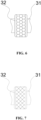
- the present application provides an anilox roller 3, and the anilox roller 3 includes a roller body 31 and an annular boss 32 formed on a surface of the roller body 31.
- the annular boss 32 extends in a circumferential direction of the roller body 31.
- the annular boss 32 includes a circumferential surface 321, a first side surface 322, and a second side surface 323.
- the first side surface 322 and the second side surface 323 face each other in an axial direction of the roller body 31.
- the circumferential surface 321 connects the first side surface 322 and the second side surface 323, and the circumferential surface 321 includes an anilox region 324 having an etched anilox.
- a first blank region 325 without an etched anilox is arranged between the anilox region 324 and the first side surface 322.
- the roller body 31 may be a cylinder, a cuboid, a prism, or the like.
- the roller body 31 is a cylinder, and the surface of the roller body 31 is a curved surface of the cylinder.
- the anilox may be hexagonal, rhombic, pentagonal, octagonal, polyline-shaped, and the like.
- a slurry will not be bonded near a joint of the first side surface 322 of the annular boss 32 and the circumferential surface 321, which can reduce the possibility of a change of a coating width of the substrate 2 caused by a wrap angle fluctuation of an edge of the annular boss 32 on the substrate 2, and can improve the coating consistency of the anilox roller 3 when coating the slurry.
- a first arc chamfer 326 is formed between the circumferential surface 321 and the first side surface 322, a radius of the first arc chamfer 326 is R 1 , and a width of the first blank region 325 is W 1 , meeting W 1 ⁇ R 1 .
- W 1 ⁇ R 1 indicates that the first arc chamfer 326 is located in the first blank region 325, and the first arc chamfer 326 will not etch the anilox.
- the arrangement of the first arc chamfer can reduce the possibility of scratching the substrate 2 by the annular boss 32. There is no need to etch the anilox on the surface of the first arc chamfer 326, which reduces the difficulty of etching the anilox and facilitates the control of the anilox etching precision.
- 0.1 mm ⁇ R 1 ⁇ 2 mm 0.1 mm ⁇ W 1 ⁇ 2 mm.
- R 1 may be any numeral value between 0.1 mm and 2 mm, for example, 0.1 mm, 0.2 mm, 0.3 mm, 0.4 mm, 0.5 mm, 0.6 mm, 0.7 mm, 0.8 mm, 0.9 mm, 1 mm, 1.1 mm, 1.2 mm, 1.3 mm, 1.4 mm, 1.5 mm, 1.6 mm, 1.7 mm, 1.8 mm, 1.9 mm, and 2 mm.
- W 1 may be any numeral value between 0.1 mm and 2 mm, for example, 0.1 mm, 0.2 mm, 0.3 mm, 0.4 mm, 0.5 mm, 0.6 mm, 0.7 mm, 0.8 mm, 0.9 mm, 1 mm, 1.1 mm, 1.2 mm, 1.3 mm, 1.4 mm, 1.5 mm, 1.6 mm, 1.7 mm, 1.8 mm, 1.9 mm, and 2 mm.
- Setting R 1 within a reasonable range is capable of reducing the risk of scratching the substrate 2 by the annular boss 32 due to too small R 1 , and on the other hand, is capable of alleviating the problem of increased production costs due to too large R 1 .
- Controlling W 1 within a reasonable range is capable of reducing the possibility of a change in a transverse width of the coating due to too small W 1 , and on the other hand, is capable of alleviating the problem of increased production costs due to too large W 1 .
- a second blank region 327 without an etched anilox is arranged between the anilox region 324 and the second side surface 323.
- the width of the first blank region 325 and the width of the second blank region 327 may be the same or different.
- the slurry will not be bonded near a joint of the first side surface 322 and the circumferential surface 321 of the annular boss 32 and near a joint of the second side surface 323 and the circumferential surface 321, which can further reduce the possibility of the change of the transverse width of the coating and improve the coating consistency when the anilox roller 3 is coating the slurry.
- a second arc chamfer 328 is formed between the circumferential surface 321 and the second side surface 323, a radius of the second arc chamfer 328 is R 2 , and a width of the second blank region 327 is W 2 , meeting W 2 ⁇ R 2 .
- W 2 ⁇ R 2 indicates that the second arc chamfer 328 is located in the second blank region 327, and the second arc chamfer 328 will not etch the anilox.
- the arrangement of the second arc chamfer 328 can reduce the possibility of scratching the substrate 2 by the annular boss 32. There is no need to etch the anilox on the surface of the first arc chamfer 326, which reduces the difficulty of etching the anilox and facilitates the control of the anilox etching precision.
- 0.1 mm ⁇ R 2 ⁇ 2 mm 0.1 mm ⁇ W 2 ⁇ 2 mm.
- R 2 may be any numeral value between 0.1 mm and 2 mm, for example, 0.1 mm, 0.2 mm, 0.3 mm, 0.4 mm, 0.5 mm, 0.6 mm, 0.7 mm, 0.8 mm, 0.9 mm, 1 mm, 1.1 mm, 1.2 mm, 1.3 mm, 1.4 mm, 1.5 mm, 1.6 mm, 1.7 mm, 1.8 mm, 1.9 mm, and 2 mm.
- W 2 may be any numeral value between 0.1 mm and 2 mm, for example, 0.1 mm, 0.2 mm, 0.3 mm, 0.4 mm, 0.5 mm, 0.6 mm, 0.7 mm, 0.8 mm, 0.9 mm, 1 mm, 1.1 mm, 1.2 mm, 1.3 mm, 1.4 mm, 1.5 mm, 1.6 mm, 1.7 mm, 1.8 mm, 1.9 mm, and 2 mm.
- Setting R 2 within a reasonable range is capable of reducing the risk of scratching the substrate 2 by the annular boss 32 due to too small R 2 , and on the other hand, is capable of alleviating the problem of increased production costs due to too large R 2 .
- Controlling W 2 within a reasonable range is capable of reducing the possibility of a change in a transverse width of the coating due to too small W 2 , and on the other hand, is capable of alleviating the problem of increased production costs due to too large W 2 .
- a height H of the annular boss 32 protruding from the surface of the roller body 31 is H, meeting 1 mm ⁇ H ⁇ 60 mm.
- the roller body 31 is a cylinder
- H is a difference between an outer diameter of a torus of the annular boss 32 and a diameter of the roller shaft 11 of the roller body 31.
- H may be any numeral value between 1 mm and 60 mm, for example, 1 mm, 5 mm, 10 mm, 15 mm, 20 mm, 25 mm, 30 mm, 35 mm, 40 mm, 45 mm, 50 mm, 55 mm, and 60 mm.
- Setting H within a reasonable range is capable of reducing the possibility of interference of the roller body 31 due to too small H. On the other hand, it is capable of alleviating the problem of increased production cost due to too large H.
- H may be any numeral value between 15 mm and 25 mm, for example, 15 mm, 20 mm, and 25 mm.
- the anilox of the anilox region 324 is hexagonal, rhombic, or polyline-shaped.
- Sizes of the aniloxs may be the same or different.
- the anilox of the anilox region 324 is hexagonal, and the anilox region 324 is covered with a plurality of hexagonal aniloxs. Circumscribed circle diameters of different hexagonal aniloxs may be the same or different.
- the anilox in the anilox region 324 being hexagonal and rhombic improves the coating efficiency and coating quality, and the anilox in the anilox region 324 being polyline-shaped can reduce the difficulty of etching the anilox.
- a plurality of annular bosses 32 are provided, and the plurality of annular bosses 32 are arranged at intervals in the axial direction of the roller body 31.
- Distances between adjacent annular bosses 32 may be the same or different.
- the present application provides a coating apparatus, which includes a workpiece tray provided with an accommodating space and the anilox roller 3 in the above embodiment, and the roller body 31 is mounted in the accommodating space in a rolling way.
- the present application provides an anilox roller 3, the anilox roller 3 includes a roller body 31 and an annular boss 32 formed on the surface of the roller body 31, the annular boss 32 extends in a circumferential direction of the roller body 31, and the annular boss 32 forms a protruding portion, such that the anilox roller 3 becomes a stepped microgravure anilox roller 3.
- the annular boss 32 includes a circumferential surface 321, a first side surface 322, and a second side surface 323.
- the first side surface 322 and the second side surface 323 face each other in an axial direction of the roller body 31.
- the circumferential surface 321 connects the first side surface 322 and the second side surface 323, and the circumferential surface 321 includes an anilox region 324 having an etched anilox.
- a first blank region 325 without an etched anilox is arranged between the anilox region 324 and the first side surface 322.
- a first arc chamfer 326 is formed between the circumferential surface 321 and the first side surface 322, a radius of the first arc chamfer 326 is R 1 , and a width of the first blank region 325 is W 1 , meeting W 1 ⁇ R 1 .
- R 1 is 0.2 mm, and W 1 is 0.3 mm.
- a second blank region 327 without an etched anilox is arranged between the anilox region 324 and the second side surface 323.
- a second arc chamfer 328 is formed between the circumferential surface 321 and the second side surface 323, a radius of the second arc chamfer 328 is R 2 , and a width of the second blank region 327 is W 2 , meeting W 2 ⁇ R 2.
- R 2 is 0.2 mm
- W 2 is 0.3 mm.
- the height of the annular boss 32 protruding from the surface of the roller body 31 is H, and H is 20 mm.
- the anilox of the anilox region 324 is hexagonal, two annular bosses 32 are provided, and the two annular bosses 32 are arranged at an interval in the circumferential direction of the roller body 31.
Landscapes
- Engineering & Computer Science (AREA)
- Manufacturing & Machinery (AREA)
- Chemical & Material Sciences (AREA)
- Chemical Kinetics & Catalysis (AREA)
- Electrochemistry (AREA)
- General Chemical & Material Sciences (AREA)
- Rolls And Other Rotary Bodies (AREA)
- Coating Apparatus (AREA)
Abstract
Description
- The present application relates to the technical field of battery coating devices, and in particular, to an anilox roller and a coating apparatus.
- Coating is an essential process in the production of battery cells, and also a key process that directly affects the safety, capacity, life, and other performances of batteries.
- An anilox roller is an important component of a coating apparatus. An anilox on the anilox roller can bond a slurry and then evenly coat the slurry to a surface of a substrate.
- During the coating process, in order to avoid interference of an anilox roller, a stepped anilox roller may be selected for coating processing, but when the stepped anilox roller is used for coating a slurry, there is a problem of poor coating consistency.
- In view of the above problems, the present application provides an anilox roller and a coating apparatus, which is capable of improving the coating consistency of the anilox roller when coating a slurry.
- In a first aspect, the present application provides an anilox roller, and the anilox roller includes a roller body and an annular boss formed on a surface of the roller body. The annular boss extends in a circumferential direction of the roller body. The annular boss includes a circumferential surface, a first side surface, and a second side surface. The first side surface and the second side surface face each other in an axial direction of the roller body. The circumferential surface connects the first side surface and the second side surface, and the circumferential surface includes an anilox region having an etched anilox. A first blank region without an etched anilox is arranged between the anilox region and the first side surface.
- In the technical solution of the embodiments of the present application, by arranging the first blank region without an etched anilox between the anilox region and the first side surface, a slurry will not be bonded near a joint of the first side surface of the annular boss and the circumferential surface, which can reduce the possibility of a change of a substrate coating width caused by a wrap angle fluctuation of an edge of the annular boss on the substrate, and can improve the coating consistency of the anilox roller when coating the slurry.
- In some embodiments, a first arc chamfer is formed between the circumferential surface and the first side surface, a radius of the first arc chamfer is R1, and a width of the first blank region is W1, meeting W1≥ R1. The arrangement of the first arc chamfer can reduce the possibility of scratching the substrate by the annular boss. W1≥R1 can reduce the difficulty of etching the anilox.
- In some embodiments, 0.1 mm≤R1≤2 mm, and 0.1 mm≤W1≤2 mm. Setting R1 within a reasonable range, on the one hand, is capable of reducing the risk of scratching the substrate by the annular boss due to too small R1, and on the other hand, is capable of alleviating the problem of increased production costs due to too large R1. Controlling W1 within a reasonable range, on the one hand, is capable of reducing the possibility of a change in a transverse width of the coating due to too small W1, and on the other hand, is capable of alleviating the problem of increased production costs due to too large W1.
- In some embodiments, on the basis of arranging the first blank region, a second blank region without an etched anilox is arranged between the anilox region and the second side surface. With such a design, the slurry will not be bonded near a joint of the first side surface and the circumferential surface of the annular boss and near a joint of the second side surface and the circumferential surface of the annular boss, which can further reduce the possibility of the change of the transverse width of the coating and improve the coating consistency when the anilox roller is coating the slurry.
- In some embodiments, a second arc chamfer is formed between the circumferential surface and the second side surface, a radius of the second arc chamfer is R2, and a width of the second blank region is W2, meeting W2 ≥ R2. The arrangement of the second arc chamfer can reduce the possibility of scratching the substrate by the annular boss. W2≥R2 can reduce the difficulty of etching the anilox.
- In some embodiments, 0.1 mm≤R2≤2 mm, and 0.1 mm≤W2≤2 mm. Setting R2 within a reasonable range, on the one hand, is capable of reducing the risk of scratching the substrate by the annular boss due to too small R2, and on the other hand, is capable of alleviating the problem of increased production costs due to too large R2. Controlling W2 within a reasonable range, on the one hand, is capable of reducing the possibility of a change in a transverse width of the coating due to too small W2, and on the other hand, is capable of alleviating the problem of increased production costs due to too large W2.
- In some embodiments, a height H of the annular boss protruding from the surface of the roller body is H, meeting 1 mm≤H≤60 mm. Setting H within a reasonable range, on the one hand, is capable of reducing the possibility of interference of the roller body due to too small H. On the other hand, it is capable of alleviating the problem of increased production cost due to too large H.
- In some embodiments, 15 mm≤H≤25 mm.
- In some embodiments, the anilox in the anilox region is hexagonal, rhombic, or polyline-shaped. The anilox in the anilox region being hexagonal and rhombic improves the coating efficiency and coating quality, and the anilox in the anilox region being polyline-shaped can reduce the difficulty of etching the anilox.
- In some embodiments, a plurality of annular bosses are arranged, and the plurality of the annular bosses are arranged at intervals in the axial direction of the roller body. Such a design improves the coating efficiency.
- In a second aspect, the present application provides a coating apparatus, which includes a workpiece tray provided with an accommodating space and the anilox roller in the above embodiment, and the roller body is mounted in the accommodating space in a rolling way.
- By reading the detailed description of the preferred implementations below, various other advantages and benefits will become apparent to those of ordinary skill in the art. The drawings are for the purpose of illustrating the preferred embodiments only and are not to be considered a limitation to the present application. Moreover, in all of the drawings, the same parts are indicated by the same reference numerals. In the drawings:
-
Fig. 1 is a schematic diagram of a microgravure roller coating and processing a substrate according to some embodiments of the present application; -
Fig. 2 is a partial enlarged diagram of a position A inFig. 1 ; -
Fig. 3 is a schematic structural diagram of an anilox roller according to some embodiments of the present application; -
Fig. 4 is a partial enlarged diagram of a position B inFig. 3 ; -
Fig. 5 is a partial sectional diagram of an anilox roller according to some embodiments of the present application; -
Fig. 6 is a schematic partial structural diagram of an anilox roller according to some embodiments of the present application; -
Fig. 7 is a schematic partial structural diagram of an anilox roller according to other embodiments of the present application; and -
Fig. 8 is a schematic partial structural diagram of an anilox roller according to still other embodiments of the present application. - Reference numerals in Detailed Description are as follows:
1-Microgravure roller; 11-Roller shaft; 12-Protruding portion; 2-Substrate; 21-Substrate coating region; 3-Anilox roller; 31-Roller body; 32-Annular boss; 321-Circumferential surface; 322-First side surface; 323-Second side surface; 324-Anilox region; 325-First blank region; 326-First arc chamfer; 327-Second blank region; and 328-Second arc chamfer. - Examples of the technical solutions of the present application will be described in detail below in conjunction with the drawings. The following embodiments are only used to more clearly illustrate the technical solution of the present application, and therefore are only used as examples and cannot be used to limit the scope of protection of the present application.
- Unless otherwise defined, all technical and scientific terms used herein have the same meaning as commonly understood by those skilled in the art belonging to the technical field of the present application; the terms used herein are intended only for the purpose of describing specific examples and are not intended to limit the present application; the terms "including" and "having" and any variations thereof in the specification and the claims of the present application and in the description of drawings above are intended to cover non-exclusive inclusion.
- In the description of the embodiments of the present application, the technical terms "first", "second", and the like are used only to distinguish between different objects, and are not to be understood as indicating or implying a relative importance or implicitly specifying the number, particular order, or primary and secondary relation of the technical features indicated. In the description of the embodiments of the present application, the meaning of "a plurality of" is two or more, unless otherwise explicitly and specifically defined.
- Reference herein to "an embodiment" means that a particular feature, structure, or characteristic described in connection with the embodiment can be included in at least one embodiment of the present application. The appearance of this phrase in various places in the specification does not necessarily refer to the same embodiment, nor is it a separate or alternative embodiment that is mutually exclusive with other embodiments. It is explicitly and implicitly understood by those skilled in the art that the embodiments described herein may be combined with other embodiments.
- In the description of the embodiments of the present application, the term "a plurality of" refers to two or more (including two), and similarly, "multiple groups" refers to two or more (including two) groups, and "multiple sheets" refers to two or more (including two) sheets.
- In the description of the embodiments of the present application, the orientation or position relationship indicated by the technical terms "center," "longitudinal," "transverse," "length," "width," "thickness," "upper," "lower," "front," "back," "left," "right," "vertical," "horizontal," "top," "bottom," "inner," "outer," "clockwise," "counterclockwise," "axial," "radial," "circumferential," etc. are based on the orientation or position relationship shown in the drawings and are intended to facilitate the description of the embodiments of the present application and simplify the description only, rather than indicating or implying that the device or element referred to must have a particular orientation or be constructed and operated in a particular orientation, and therefore are not to be interpreted as limitations on the embodiments of the present application.
- In the description of the embodiments of the present application, unless otherwise expressly specified and limited, the technical terms "mount," "join," "connect," "fix," etc. should be understood in a broad sense, such as, a fixed connection, a detachable connection, or an integral connection; a mechanical connection, or an electrical connection; a direct connection, an indirect connection through an intermediate medium, an internal connection of two elements, or interaction between two elements. For those of ordinary skill in the art, the specific meanings of the above terms in the embodiments of the present application can be understood according to specific situations.
- At present, from the perspective of the development of the market situation, power batteries are more and more widely used. The power batteries are used in energy storage power source systems such as hydraulic, thermal, wind and solar power stations as well as in electric vehicles such as electric bicycles, electric motorcycles and electric cars, and military equipment and aerospace fields. With the continuous expansion of the application field of the power batteries, the market demand is also constantly expanding.
- Coating is applying a thin layer of coating material in liquid or powder form on a surface of an object such as fabric, paper, metal foil, or board. Coating is an indispensable step in a production process of battery cells.
- The battery cell includes an electrode assembly and an electrolyte solution. The electrode assembly is composed of a positive electrode sheet, a negative electrode sheet, and a separator. The battery cell operates mainly relying on movement of metal ions between the positive electrode sheet and the negative electrode sheet. The positive electrode sheet includes a positive electrode current collector and a positive electrode active material layer. The positive electrode active material layer is coated on partial of a surface of the positive electrode current collector. The positive electrode current collector not coated with the positive electrode active material layer serves as a positive tab. Taking a lithium-ion battery as an example, the material of the positive current collector may be aluminum, and the positive active material may be lithium cobalt oxide, lithium iron phosphate, ternary lithium, lithium manganate, or the like. The negative electrode sheet includes a negative electrode current collector and a negative electrode active material layer. The negative electrode active material layer is coated on partial of a surface of the negative electrode current collector. The negative electrode current collector not coated with the negative electrode active material layer serves as a negative tab. The material of the negative electrode current collector may be copper, and the negative electrode active material may be carbon, silicon, or the like. In order to ensure that no fusing occurs when a large current passes, a plurality of positive tabs stacked together are provided, and a plurality of negative tabs stacked together are provided.
- In the production process of battery cells, a coating process is used for coating the positive electrode active material on the positive electrode current collector and coating the negative electrode active material on the negative electrode current collector, that is, a prepared pasty thick slurry (the positive electrode active material or the negative electrode active material) is uniformly, continuously, or intermittently coated on the substrate (the positive electrode current collector or the negative electrode current collector). During coating, it is necessary to ensure the consistency of thicknesses of various coating positions, and control the coating thickness within a tolerance range required by the process.
- The coating apparatus used in the coating process includes a workpiece tray and an anilox roller provided with an accommodating space, the slurry may be stored in the accommodating space, and the anilox roller is mounted in the accommodating space in a rolling way. A circumferential surface of the anilox roller is sprayed with a ceramic material and etched by laser to form an anilox, and the anilox is used for bonding the slurry.
- In the coating process, in order to reduce the possibility of the anilox roller interfering with other regions and causing concave and convex points on the substrate, a stepped anilox roller, such as a microgravure roller, is generally selected. A microgravure roller generally includes a roller shaft and a protruding portion arranged in the circumferential direction of the roller shaft and protruding from a curved surface of the roller shaft. The anilox for bonding the slurry is arranged on the entire curved surface of the protruding portion.
- The inventor noticed that since the substrate is generally an aluminum foil or a copper foil, its thickness is very thin. For example, a PET copper foil uses 4.5 micron PET as the substrate, and both sides are each covered with a copper plating layer of one micron. The actual thickness is only 6.5 microns, and the material of the substrate is relatively soft. In the coating process, a part of substrate may wrap the edge of the protruding portion to have the wrap angle fluctuation, which will cause a change in the coating width of the substrate, and cause the coating consistency of the substrate worse.
- In order to solve the problem of poor coating consistency of the substrate during the coating process of the microgravure roller, the applicant has found that a blank region is arranged on the edge of the protruding portion of the microgravure roller, so that the edge of the protruding portion will not be bonded to the slurry in the coating process, which can reduce the possibility of substrate coating width changing in the coating process, and improve the coating consistency when the microgravure roller is coating the slurry.
- The coating apparatus disclosed in the embodiments of the present application may be used, but not limited to, for coating the slurry on the positive electrode current collector or the negative electrode current collector.
- For the convenience of description, the following embodiments are illustrated by taking a
microgravure roller 1 according to an embodiment of the present application as an example. - Referring to
Fig. 1 , themicrogravure roller 1 includes aroller shaft 11 and a protrudingportion 12 formed on the surface of theroller shaft 11, the protrudingportion 12 includes two opposite bottom surfaces and a curved surface, and the curved surface of the protrudingportion 12 is covered with a laser etched anilox. Referring toFig. 2 , in the coating process, an edge of asubstrate coating region 21 on asubstrate 2 may wrap around an edge of the protrudingportion 12, and the width of thesubstrate coating region 21 may fluctuate, for example, an actual width of thesubstrate coating region 21 is greater than a designed width of thesubstrate coating region 21, which deteriorates the coating consistency of themicrogravure roll 1 when coating the slurry. - In order to prevent the edge of the protruding
portion 12 from scratching thesubstrate 2, the edge of the protrudingportion 12 is generally chamfered, but it is difficult to control the precision of the anilox etched at the chamfer, so that when themicrogravure roller 1 coats the slurry, there will be a part of the slurry remaining in the anilox at the chamfer of themicrogravure roller 1. If things go on like this, the remaining slurry will deteriorate the coating consistency when themicrogravure roller 1 coats the slurry. - In some embodiments of the present application, referring to
Fig. 3 , the present application provides ananilox roller 3, and theanilox roller 3 includes aroller body 31 and anannular boss 32 formed on a surface of theroller body 31. Theannular boss 32 extends in a circumferential direction of theroller body 31. Theannular boss 32 includes acircumferential surface 321, afirst side surface 322, and asecond side surface 323. Thefirst side surface 322 and thesecond side surface 323 face each other in an axial direction of theroller body 31. Thecircumferential surface 321 connects thefirst side surface 322 and thesecond side surface 323, and thecircumferential surface 321 includes ananilox region 324 having an etched anilox. A firstblank region 325 without an etched anilox is arranged between theanilox region 324 and thefirst side surface 322. - The
roller body 31 may be a cylinder, a cuboid, a prism, or the like. Exemplarily, theroller body 31 is a cylinder, and the surface of theroller body 31 is a curved surface of the cylinder. - The anilox may be hexagonal, rhombic, pentagonal, octagonal, polyline-shaped, and the like.
- By arranging the first
blank region 325 without an etched anilox between theanilox region 324 and thefirst side surface 322, a slurry will not be bonded near a joint of thefirst side surface 322 of theannular boss 32 and thecircumferential surface 321, which can reduce the possibility of a change of a coating width of thesubstrate 2 caused by a wrap angle fluctuation of an edge of theannular boss 32 on thesubstrate 2, and can improve the coating consistency of theanilox roller 3 when coating the slurry. - According to some embodiments of the present application, referring to
Fig. 4 andFig. 5 , afirst arc chamfer 326 is formed between thecircumferential surface 321 and thefirst side surface 322, a radius of thefirst arc chamfer 326 is R1, and a width of the firstblank region 325 is W1, meeting W1≥R1. - W1≥R1 indicates that the
first arc chamfer 326 is located in the firstblank region 325, and thefirst arc chamfer 326 will not etch the anilox. - The arrangement of the first arc chamfer can reduce the possibility of scratching the
substrate 2 by theannular boss 32. There is no need to etch the anilox on the surface of thefirst arc chamfer 326, which reduces the difficulty of etching the anilox and facilitates the control of the anilox etching precision. - According to some embodiments of the present application, referring to
Fig. 4 andFig. 5 , 0.1 mm≤R1≤2 mm, and 0.1 mm≤W1≤2 mm. - R1 may be any numeral value between 0.1 mm and 2 mm, for example, 0.1 mm, 0.2 mm, 0.3 mm, 0.4 mm, 0.5 mm, 0.6 mm, 0.7 mm, 0.8 mm, 0.9 mm, 1 mm, 1.1 mm, 1.2 mm, 1.3 mm, 1.4 mm, 1.5 mm, 1.6 mm, 1.7 mm, 1.8 mm, 1.9 mm, and 2 mm.
- W1 may be any numeral value between 0.1 mm and 2 mm, for example, 0.1 mm, 0.2 mm, 0.3 mm, 0.4 mm, 0.5 mm, 0.6 mm, 0.7 mm, 0.8 mm, 0.9 mm, 1 mm, 1.1 mm, 1.2 mm, 1.3 mm, 1.4 mm, 1.5 mm, 1.6 mm, 1.7 mm, 1.8 mm, 1.9 mm, and 2 mm.
- Setting R1 within a reasonable range, on the one hand, is capable of reducing the risk of scratching the
substrate 2 by theannular boss 32 due to too small R1, and on the other hand, is capable of alleviating the problem of increased production costs due to too large R1. Controlling W1 within a reasonable range, on the one hand, is capable of reducing the possibility of a change in a transverse width of the coating due to too small W1, and on the other hand, is capable of alleviating the problem of increased production costs due to too large W1. - According to some embodiments of the present application, referring to
Fig. 4 andFig. 5 , on the basis of arranging the firstblank region 325, a secondblank region 327 without an etched anilox is arranged between theanilox region 324 and thesecond side surface 323. - The width of the first
blank region 325 and the width of the secondblank region 327 may be the same or different. - With such a design, the slurry will not be bonded near a joint of the
first side surface 322 and thecircumferential surface 321 of theannular boss 32 and near a joint of thesecond side surface 323 and thecircumferential surface 321, which can further reduce the possibility of the change of the transverse width of the coating and improve the coating consistency when theanilox roller 3 is coating the slurry. - According to some embodiments of the present application, referring to
Fig. 4 andFig. 5 , asecond arc chamfer 328 is formed between thecircumferential surface 321 and thesecond side surface 323, a radius of thesecond arc chamfer 328 is R2, and a width of the secondblank region 327 is W2, meeting W2≥R2. - W2≥R2 indicates that the
second arc chamfer 328 is located in the secondblank region 327, and thesecond arc chamfer 328 will not etch the anilox. - The arrangement of the
second arc chamfer 328 can reduce the possibility of scratching thesubstrate 2 by theannular boss 32. There is no need to etch the anilox on the surface of thefirst arc chamfer 326, which reduces the difficulty of etching the anilox and facilitates the control of the anilox etching precision. - According to some embodiments of the present application, referring to
Fig. 4 andFig. 5 , 0.1 mm≤R2≤2 mm, and 0.1 mm≤W2≤2 mm. - R2 may be any numeral value between 0.1 mm and 2 mm, for example, 0.1 mm, 0.2 mm, 0.3 mm, 0.4 mm, 0.5 mm, 0.6 mm, 0.7 mm, 0.8 mm, 0.9 mm, 1 mm, 1.1 mm, 1.2 mm, 1.3 mm, 1.4 mm, 1.5 mm, 1.6 mm, 1.7 mm, 1.8 mm, 1.9 mm, and 2 mm.
- W2 may be any numeral value between 0.1 mm and 2 mm, for example, 0.1 mm, 0.2 mm, 0.3 mm, 0.4 mm, 0.5 mm, 0.6 mm, 0.7 mm, 0.8 mm, 0.9 mm, 1 mm, 1.1 mm, 1.2 mm, 1.3 mm, 1.4 mm, 1.5 mm, 1.6 mm, 1.7 mm, 1.8 mm, 1.9 mm, and 2 mm.
- Setting R2 within a reasonable range, on the one hand, is capable of reducing the risk of scratching the
substrate 2 by theannular boss 32 due to too small R2, and on the other hand, is capable of alleviating the problem of increased production costs due to too large R2. Controlling W2 within a reasonable range, on the one hand, is capable of reducing the possibility of a change in a transverse width of the coating due to too small W2, and on the other hand, is capable of alleviating the problem of increased production costs due to too large W2. - According to some embodiments of the present application, referring to
Fig. 5 , a height H of theannular boss 32 protruding from the surface of theroller body 31 is H, meeting 1 mm≤H≤60 mm. - Exemplarily, the
roller body 31 is a cylinder, and H is a difference between an outer diameter of a torus of theannular boss 32 and a diameter of theroller shaft 11 of theroller body 31. - H may be any numeral value between 1 mm and 60 mm, for example, 1 mm, 5 mm, 10 mm, 15 mm, 20 mm, 25 mm, 30 mm, 35 mm, 40 mm, 45 mm, 50 mm, 55 mm, and 60 mm.
- Setting H within a reasonable range, on the one hand, is capable of reducing the possibility of interference of the
roller body 31 due to too small H. On the other hand, it is capable of alleviating the problem of increased production cost due to too large H. - According to some embodiments of the present application, referring to
Fig. 5 , 15 mm≤H≤25 mm. - H may be any numeral value between 15 mm and 25 mm, for example, 15 mm, 20 mm, and 25 mm.
- According to some embodiments of the present application, referring to
Fig. 6 to Fig. 8 , the anilox of theanilox region 324 is hexagonal, rhombic, or polyline-shaped. - Sizes of the aniloxs may be the same or different. Exemplarily, the anilox of the
anilox region 324 is hexagonal, and theanilox region 324 is covered with a plurality of hexagonal aniloxs. Circumscribed circle diameters of different hexagonal aniloxs may be the same or different. - The anilox in the
anilox region 324 being hexagonal and rhombic improves the coating efficiency and coating quality, and the anilox in theanilox region 324 being polyline-shaped can reduce the difficulty of etching the anilox. - According to some embodiments of the present application, referring to
Fig. 3 , a plurality ofannular bosses 32 are provided, and the plurality ofannular bosses 32 are arranged at intervals in the axial direction of theroller body 31. - Distances between adjacent
annular bosses 32 may be the same or different. - Such a design improves the coating efficiency.
- According to some embodiments of the present application, the present application provides a coating apparatus, which includes a workpiece tray provided with an accommodating space and the
anilox roller 3 in the above embodiment, and theroller body 31 is mounted in the accommodating space in a rolling way. - According to some embodiments of the present application, referring to
Fig. 3 to Fig. 8 , the present application provides ananilox roller 3, theanilox roller 3 includes aroller body 31 and anannular boss 32 formed on the surface of theroller body 31, theannular boss 32 extends in a circumferential direction of theroller body 31, and theannular boss 32 forms a protruding portion, such that theanilox roller 3 becomes a steppedmicrogravure anilox roller 3. - The
annular boss 32 includes acircumferential surface 321, afirst side surface 322, and asecond side surface 323. Thefirst side surface 322 and thesecond side surface 323 face each other in an axial direction of theroller body 31. Thecircumferential surface 321 connects thefirst side surface 322 and thesecond side surface 323, and thecircumferential surface 321 includes ananilox region 324 having an etched anilox. - A first
blank region 325 without an etched anilox is arranged between theanilox region 324 and thefirst side surface 322. Afirst arc chamfer 326 is formed between thecircumferential surface 321 and thefirst side surface 322, a radius of thefirst arc chamfer 326 is R1, and a width of the firstblank region 325 is W1, meeting W1≥R1. R1 is 0.2 mm, and W1 is 0.3 mm. A secondblank region 327 without an etched anilox is arranged between theanilox region 324 and thesecond side surface 323. Asecond arc chamfer 328 is formed between thecircumferential surface 321 and thesecond side surface 323, a radius of thesecond arc chamfer 328 is R2, and a width of the secondblank region 327 is W2, meeting W2≥R2. R2 is 0.2 mm, and W2 is 0.3 mm. The height of theannular boss 32 protruding from the surface of theroller body 31 is H, and H is 20 mm. - The anilox of the
anilox region 324 is hexagonal, twoannular bosses 32 are provided, and the twoannular bosses 32 are arranged at an interval in the circumferential direction of theroller body 31. - The above are only preferred examples of the present application, and are not intended to limit the present application. For those skilled in the art, the present application may have various modifications and changes. Any modifications, equivalent replacements, improvements, and the like made within the spirit and principle of the present application shall be included within the scope of protection of the present application.
Claims (11)
- An anilox roller, comprising a roller body and an annular boss formed on a surface of the roller body, the annular boss extending in a circumferential direction of the roller body, the annular boss comprising a circumferential surface, a first side surface, and a second side surface, the first side surface and the second side surface facing each other in an axial direction of the roller body, the circumferential surface connecting the first side surface and the second side surface, and the circumferential surface comprising an anilox region having an etched anilox;
wherein a first blank region without an etched anilox is arranged between the anilox region and the first side surface. - The anilox roller according to claim 1, wherein a first arc chamfer is formed between the circumferential surface and the first side surface, a radius of the first arc chamfer is R1, and a width of the first blank region is W1, meeting W1≥R1.
- The anilox roller according to claim 2, wherein 0.1 mm≤R1≤2 mm, and 0.1 mm≤W1≤2 mm.
- The anilox roller according to claim 1, wherein a second blank region without an etched anilox is arranged between the anilox region and the second side surface.
- The anilox roller according to claim 4, wherein a second arc chamfer is formed between the circumferential surface and the second side surface, a radius of the second arc chamfer is R2, and a width of the second blank region is W2, meeting W2≥R2.
- The anilox roller according to claim 5, wherein 0.1 mm≤R2≤2 mm, and 0.1 mm≤W2≤2 mm.
- The anilox roller according to claim 1, wherein a height of the annular boss protruding from the surface of the roller body is H, meeting 1 mm≤H≤60 mm.
- The anilox roller according to claim 7, wherein 15 mm≤H≤25 mm.
- The anilox roller according to claim 8, wherein the anilox in the anilox region is hexagonal, rhombic, or polyline-shaped.
- The anilox roller according to claim 1, wherein a plurality of annular bosses are provided, and the plurality of the annular bosses are arranged at intervals in the axial direction of the roller body.
- A coating apparatus, comprising a workpiece tray with an accommodating space and the anilox roller according to any one of claims 1 to 10, wherein the roller body is mounted in the accommodating space in a rolling way.
Applications Claiming Priority (1)
| Application Number | Priority Date | Filing Date | Title |
|---|---|---|---|
| CN202222447529.0U CN218394395U (en) | 2022-09-15 | 2022-09-15 | Anilox roll and coating device |
Publications (3)
| Publication Number | Publication Date |
|---|---|
| EP4349495A1 true EP4349495A1 (en) | 2024-04-10 |
| EP4349495B1 EP4349495B1 (en) | 2025-12-03 |
| EP4349495C0 EP4349495C0 (en) | 2025-12-03 |
Family
ID=85032664
Family Applications (1)
| Application Number | Title | Priority Date | Filing Date |
|---|---|---|---|
| EP23165287.6A Active EP4349495B1 (en) | 2022-09-15 | 2023-03-30 | Anilox roller and coating apparatus |
Country Status (4)
| Country | Link |
|---|---|
| US (1) | US20240091805A1 (en) |
| EP (1) | EP4349495B1 (en) |
| CN (1) | CN218394395U (en) |
| ES (1) | ES3063056T3 (en) |
Families Citing this family (1)
| Publication number | Priority date | Publication date | Assignee | Title |
|---|---|---|---|---|
| CN116943945A (en) * | 2022-04-18 | 2023-10-27 | 宁德时代新能源科技股份有限公司 | Coating device, pole piece production system and method |
Citations (2)
| Publication number | Priority date | Publication date | Assignee | Title |
|---|---|---|---|---|
| CN113130839B (en) * | 2021-04-13 | 2022-05-10 | 中创新航科技股份有限公司 | Preparation method of battery pole piece, die head gasket and battery |
| CN216965184U (en) * | 2021-11-12 | 2022-07-15 | 比亚迪股份有限公司 | Anilox roller and coating machine |
-
2022
- 2022-09-15 CN CN202222447529.0U patent/CN218394395U/en active Active
-
2023
- 2023-03-30 ES ES23165287T patent/ES3063056T3/en active Active
- 2023-03-30 EP EP23165287.6A patent/EP4349495B1/en active Active
- 2023-03-30 US US18/192,737 patent/US20240091805A1/en active Pending
Patent Citations (2)
| Publication number | Priority date | Publication date | Assignee | Title |
|---|---|---|---|---|
| CN113130839B (en) * | 2021-04-13 | 2022-05-10 | 中创新航科技股份有限公司 | Preparation method of battery pole piece, die head gasket and battery |
| CN216965184U (en) * | 2021-11-12 | 2022-07-15 | 比亚迪股份有限公司 | Anilox roller and coating machine |
Also Published As
| Publication number | Publication date |
|---|---|
| EP4349495B1 (en) | 2025-12-03 |
| EP4349495C0 (en) | 2025-12-03 |
| US20240091805A1 (en) | 2024-03-21 |
| ES3063056T3 (en) | 2026-04-15 |
| CN218394395U (en) | 2023-01-31 |
Similar Documents
| Publication | Publication Date | Title |
|---|---|---|
| CN111668451B (en) | A method for preparing pole pieces for wound multi-pole batteries, pole pieces and batteries | |
| US12212022B2 (en) | Multi-tab cylindrical battery roll core and lithium ion battery | |
| US20250273825A1 (en) | Electrode component, battery cell, battery and electrical apparatus | |
| US12199315B2 (en) | Battery cell, battery, power consumption device and battery cell manufaturing method and device | |
| US11978879B1 (en) | Deviation-correcting method and apparatus for double-sided coating | |
| US11944995B2 (en) | Coating system | |
| US20240274777A1 (en) | Electrode sheet forming method, manufacturing method for wound electrode assembly, and manufacturing method for laminated electrode assembly | |
| US12278341B2 (en) | Electrode assembly, battery cell, battery, and electrical device | |
| EP4349495A1 (en) | Anilox roller and coating apparatus | |
| US12315960B2 (en) | Current collecting member and manufacturing method thereof, secondary battery and manufacturing method thereof, battery module, and apparatus | |
| CN117913376B (en) | Core structure and battery | |
| CN118763365B (en) | Battery cell, preparation method, manufacturing equipment, battery device and power-using device | |
| US20240266616A1 (en) | Electrode plate and manufacturing method thereof, electrode assembly and manufacturing method thereof, battery cell, and battery | |
| US20240396007A1 (en) | Power storage cell | |
| US20240339626A1 (en) | Electrode assembly, battery cell, battery, and electric device | |
| CN218395460U (en) | Rolling mechanism and pole piece manufacturing equipment | |
| CN116365118A (en) | Forming method of square battery cell shell, square battery cell and battery pack | |
| CN222642395U (en) | Coating die head and coating device | |
| CN221581026U (en) | Coating die head | |
| CN222106760U (en) | A pole piece structure, battery cell and battery | |
| US20250149620A1 (en) | Power storage cell | |
| CN219917537U (en) | Battery pole piece, battery core and battery pack | |
| CN222190863U (en) | A battery cell and a battery | |
| CN223693140U (en) | Positive plate, battery cell and battery | |
| CN219917516U (en) | Battery pole piece, battery pole group and battery |
Legal Events
| Date | Code | Title | Description |
|---|---|---|---|
| PUAI | Public reference made under article 153(3) epc to a published international application that has entered the european phase |
Free format text: ORIGINAL CODE: 0009012 |
|
| STAA | Information on the status of an ep patent application or granted ep patent |
Free format text: STATUS: REQUEST FOR EXAMINATION WAS MADE |
|
| 17P | Request for examination filed |
Effective date: 20230330 |
|
| AK | Designated contracting states |
Kind code of ref document: A1 Designated state(s): AL AT BE BG CH CY CZ DE DK EE ES FI FR GB GR HR HU IE IS IT LI LT LU LV MC ME MK MT NL NO PL PT RO RS SE SI SK SM TR |
|
| RAP1 | Party data changed (applicant data changed or rights of an application transferred) |
Owner name: CONTEMPORARY AMPEREX TECHNOLOGY(HONG KONG) LIMITED |
|
| RIC1 | Information provided on ipc code assigned before grant |
Ipc: B05C 1/08 20060101AFI20250707BHEP Ipc: H01M 4/04 20060101ALI20250707BHEP Ipc: H01M 50/403 20210101ALI20250707BHEP |
|
| GRAP | Despatch of communication of intention to grant a patent |
Free format text: ORIGINAL CODE: EPIDOSNIGR1 |
|
| STAA | Information on the status of an ep patent application or granted ep patent |
Free format text: STATUS: GRANT OF PATENT IS INTENDED |
|
| INTG | Intention to grant announced |
Effective date: 20250911 |
|
| GRAS | Grant fee paid |
Free format text: ORIGINAL CODE: EPIDOSNIGR3 |
|
| GRAA | (expected) grant |
Free format text: ORIGINAL CODE: 0009210 |
|
| STAA | Information on the status of an ep patent application or granted ep patent |
Free format text: STATUS: THE PATENT HAS BEEN GRANTED |
|
| AK | Designated contracting states |
Kind code of ref document: B1 Designated state(s): AL AT BE BG CH CY CZ DE DK EE ES FI FR GB GR HR HU IE IS IT LI LT LU LV MC ME MK MT NL NO PL PT RO RS SE SI SK SM TR |
|
| REG | Reference to a national code |
Ref country code: CH Ref legal event code: F10 Free format text: ST27 STATUS EVENT CODE: U-0-0-F10-F00 (AS PROVIDED BY THE NATIONAL OFFICE) Effective date: 20251203 Ref country code: GB Ref legal event code: FG4D |
|
| REG | Reference to a national code |
Ref country code: DE Ref legal event code: R096 Ref document number: 602023009146 Country of ref document: DE |
|
| REG | Reference to a national code |
Ref country code: IE Ref legal event code: FG4D |
|
| U01 | Request for unitary effect filed |
Effective date: 20251219 |
|
| U07 | Unitary effect registered |
Designated state(s): AT BE BG DE DK EE FI FR IT LT LU LV MT NL PT RO SE SI Effective date: 20260105 |
|
| PG25 | Lapsed in a contracting state [announced via postgrant information from national office to epo] |
Ref country code: NO Free format text: LAPSE BECAUSE OF FAILURE TO SUBMIT A TRANSLATION OF THE DESCRIPTION OR TO PAY THE FEE WITHIN THE PRESCRIBED TIME-LIMIT Effective date: 20260303 |
|
| PG25 | Lapsed in a contracting state [announced via postgrant information from national office to epo] |
Ref country code: HR Free format text: LAPSE BECAUSE OF FAILURE TO SUBMIT A TRANSLATION OF THE DESCRIPTION OR TO PAY THE FEE WITHIN THE PRESCRIBED TIME-LIMIT Effective date: 20251203 |
|
| REG | Reference to a national code |
Ref country code: ES Ref legal event code: FG2A Ref document number: 3063056 Country of ref document: ES Kind code of ref document: T3 Effective date: 20260415 |
|
| PG25 | Lapsed in a contracting state [announced via postgrant information from national office to epo] |
Ref country code: RS Free format text: LAPSE BECAUSE OF FAILURE TO SUBMIT A TRANSLATION OF THE DESCRIPTION OR TO PAY THE FEE WITHIN THE PRESCRIBED TIME-LIMIT Effective date: 20260303 |
|
| PG25 | Lapsed in a contracting state [announced via postgrant information from national office to epo] |
Ref country code: PL Free format text: LAPSE BECAUSE OF FAILURE TO SUBMIT A TRANSLATION OF THE DESCRIPTION OR TO PAY THE FEE WITHIN THE PRESCRIBED TIME-LIMIT Effective date: 20251203 |
|
| U20 | Renewal fee for the european patent with unitary effect paid |
Year of fee payment: 4 Effective date: 20260325 |